Realtime 3D Computer GraphicsVirtual Reality
Graphics

Realtime 3D Computer Graphics / Virtual Reality – WS 2006/2007 – Marc Erich Latoschik
Computer graphicstennis for two
pongspacewar
(from l. to r.)
• 3D-Computer graphics (3D-CG) currently used for• Simulators, VR, Games (real-time)• Design (CAD)• Entertainment (Movies), Art• Education
Realtime 3D Computer Graphics / Virtual Reality – WS 2006/2007 – Marc Erich Latoschik
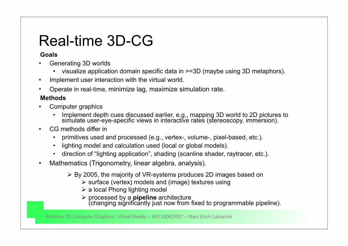
Real-time 3D-CGGoals• Generating 3D worlds
• visualize application domain specific data in >=3D (maybe using 3D metaphors).• Implement user interaction with the virtual world.• Operate in real-time, minimize lag, maximize simulation rate.Methods• Computer graphics
• Implement depth cues discussed earlier, e.g., mapping 3D world to 2D pictures to simulate user-eye-specific views in interactive rates (stereoscopy, immersion).
• CG methods differ in• primitives used and processed (e.g., vertex-, volume-, pixel-based, etc.). • lighting model and calculation used (local or global models).• direction of “lighting application”, shading (scanline shader, raytracer, etc.).
• Mathematics (Trigonometry, linear algebra, analysis).
By 2005, the majority of VR-systems produces 2D images based on surface (vertex) models and (image) textures using a local Phong lighting model processed by a pipeline architecture
(changing significantly just now from fixed to programmable pipeline).

Realtime 3D Computer Graphics / Virtual Reality – WS 2006/2007 – Marc Erich Latoschik
The 3D-pipeline
• application stage• geometry stage
• model and view transform• lighting (shading in rasterizer)• projection• clipping• screen mapping
• rasterizer stage• visibility (z-buffer)• shading• texturing
Application Geometry Rasterizer
Model & ViewTransform Lighting Projection Clipping Screen
Mapping
parallelization on different stages
Realtime 3D Computer Graphics / Virtual Reality – WS 2006/2007 – Marc Erich Latoschik
The 3D-pipelineModelObject
Specify ViewCalculate Normal
IlluminationBackface
Scale,Rotate
Translate,Object
Apply Normalizing
Transformation,Clip
Removehidden
surfaces
Shade,Texture
Map to Viewport/Draw toScreen
PerspectiveTransformation
/Projection
objectspace
world(eye)space
world(eye)space
normalizedeye space
imagespace
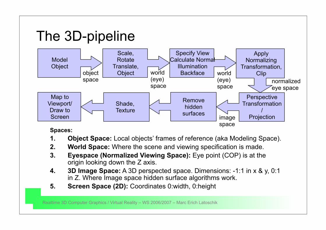
Spaces:1. Object Space: Local objects’ frames of reference (aka Modeling Space).2. World Space: Where the scene and viewing specification is made.3. Eyespace (Normalized Viewing Space): Eye point (COP) is at the
origin looking down the Z axis.4. 3D Image Space: A 3D perspected space. Dimensions: -1:1 in x & y, 0:1
in Z. Where Image space hidden surface algorithms work.5. Screen Space (2D): Coordinates 0:width, 0:height
Realtime 3D Computer Graphics / Virtual Reality – WS 2006/2007 – Marc Erich Latoschik
ModelObject
Specify ViewCalculate Normal
IlluminationBackface
Scale,Rotate
Translate,Object
Apply Normalizing
Transformation,Clip
Removehidden
surfacesShade,Texture
Map to Viewport
/Draw toScreen
PerspectiveTransformation/Projection
objectspace
worldspace
worldspace
eyespace
imagespace
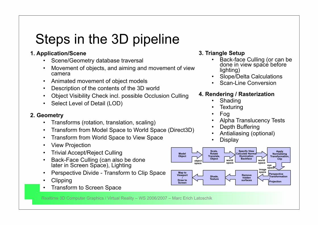
Steps in the 3D pipeline1. Application/Scene
• Scene/Geometry database traversal • Movement of objects, and aiming and movement of view
camera • Animated movement of object models • Description of the contents of the 3D world • Object Visibility Check incl. possible Occlusion Culling • Select Level of Detail (LOD)
2. Geometry• Transforms (rotation, translation, scaling) • Transform from Model Space to World Space (Direct3D) • Transform from World Space to View Space • View Projection • Trivial Accept/Reject Culling • Back-Face Culling (can also be done
later in Screen Space), Lighting • Perspective Divide - Transform to Clip Space • Clipping • Transform to Screen Space
3. Triangle Setup• Back-face Culling (or can be
done in view space before lighting)
• Slope/Delta Calculations • Scan-Line Conversion
4. Rendering / Rasterization• Shading • Texturing • Fog • Alpha Translucency Tests • Depth Buffering • Antialiasing (optional) • Display
Realtime 3D Computer Graphics / Virtual Reality – WS 2006/2007 – Marc Erich Latoschik
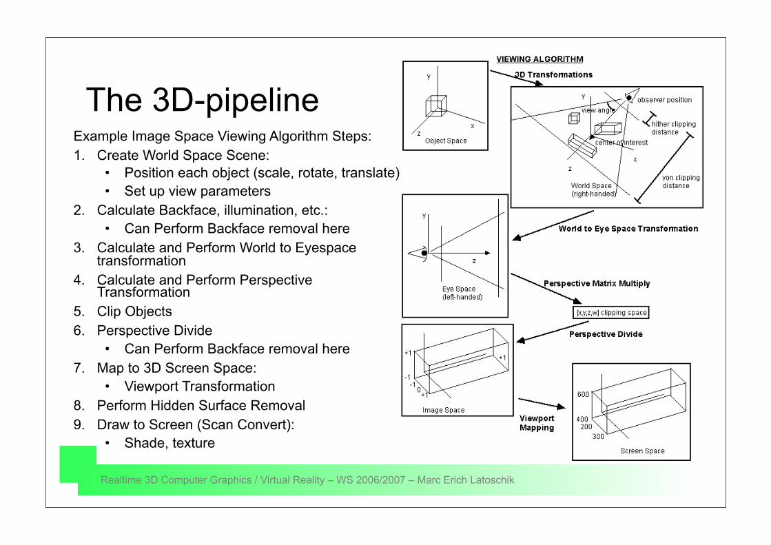
The 3D-pipelineExample Image Space Viewing Algorithm Steps:1. Create World Space Scene:
• Position each object (scale, rotate, translate) • Set up view parameters
2. Calculate Backface, illumination, etc.: • Can Perform Backface removal here
3. Calculate and Perform World to Eyespace transformation
4. Calculate and Perform Perspective Transformation
5. Clip Objects 6. Perspective Divide
• Can Perform Backface removal here7. Map to 3D Screen Space:
• Viewport Transformation8. Perform Hidden Surface Removal9. Draw to Screen (Scan Convert):
• Shade, texture
Realtime 3D Computer Graphics / Virtual Reality – WS 2006/2007 – Marc Erich Latoschik
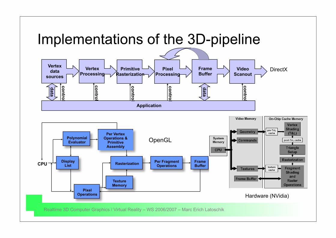
Implementations of the 3D-pipelineVertexdata
sourcesPrimitive
RasterizationVertex
ProcessingPixel
ProcessingFrameBuffer
VideoScanout
Application
data
data
control
control
control
control
control
DirectX
DisplayList
PolynomialEvaluator
Per VertexOperations &
PrimitiveAssembly
Rasterization Per FragmentOperations
FrameBuffer
TextureMemory
CPU
PixelOperations
OpenGL
Hardware (NVidia)
Realtime 3D Computer Graphics / Virtual Reality – WS 2006/2007 – Marc Erich Latoschik
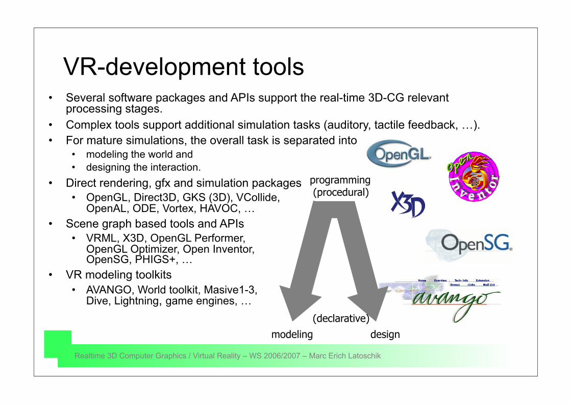
VR-development tools• Several software packages and APIs support the real-time 3D-CG relevant
processing stages.• Complex tools support additional simulation tasks (auditory, tactile feedback, …).• For mature simulations, the overall task is separated into
• modeling the world and • designing the interaction.
• Direct rendering, gfx and simulation packages• OpenGL, Direct3D, GKS (3D), VCollide,
OpenAL, ODE, Vortex, HAVOC, …• Scene graph based tools and APIs
• VRML, X3D, OpenGL Performer, OpenGL Optimizer, Open Inventor, OpenSG, PHIGS+, …
• VR modeling toolkits• AVANGO, World toolkit, Masive1-3,
Dive, Lightning, game engines, …
designmodeling
programming (procedural)
(declarative)
Realtime 3D Computer Graphics / Virtual Reality – WS 2006/2007 – Marc Erich Latoschik
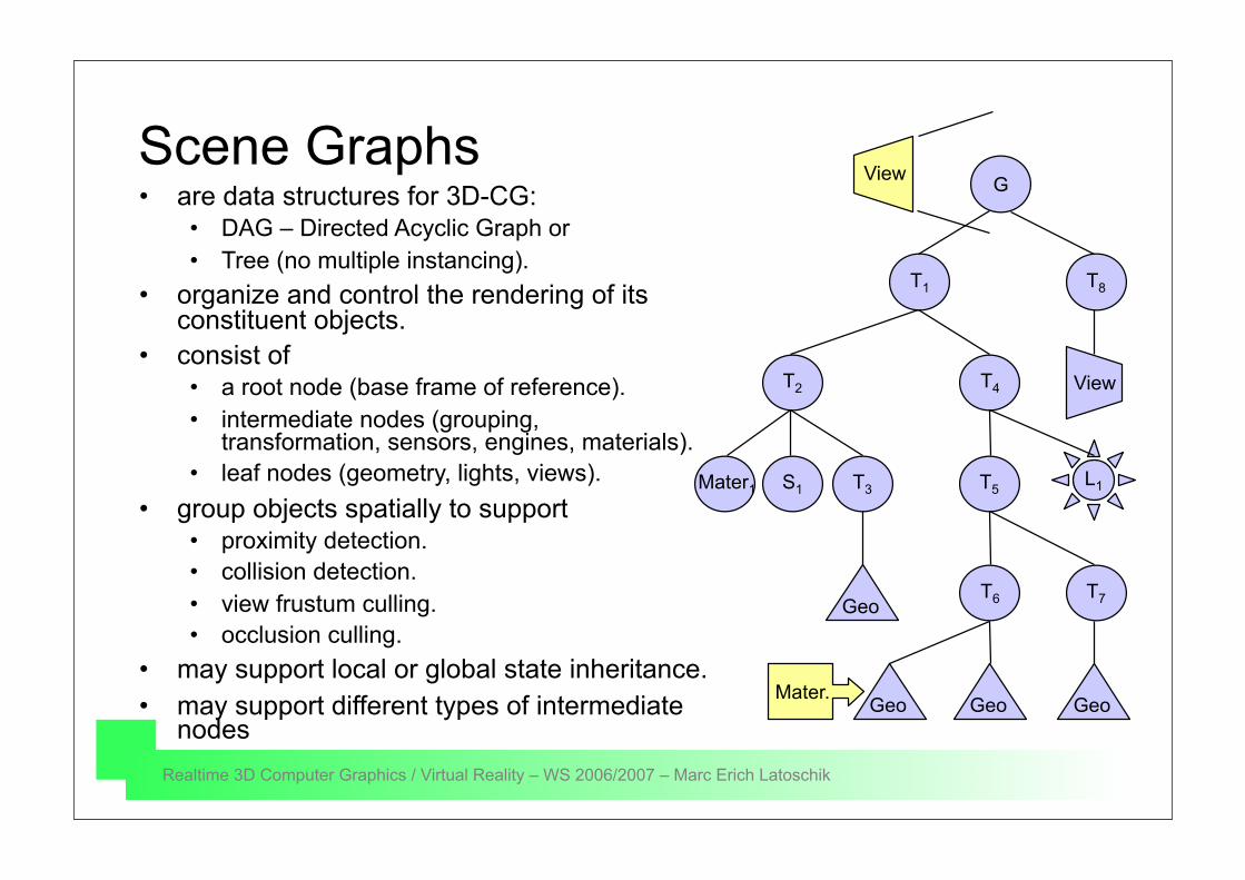
Scene Graphs• are data structures for 3D-CG:
• DAG – Directed Acyclic Graph or• Tree (no multiple instancing).
• organize and control the rendering of its constituent objects.
• consist of • a root node (base frame of reference).• intermediate nodes (grouping,
transformation, sensors, engines, materials).• leaf nodes (geometry, lights, views).
• group objects spatially to support• proximity detection.• collision detection.• view frustum culling.• occlusion culling.
• may support local or global state inheritance.• may support different types of intermediate
nodes
T8T1
T4
G
T2
T5
Geo
View
Mater1 S1 T3
GeoT6 T7
GeoGeo
L1
Mater.
View
Realtime 3D Computer Graphics / Virtual Reality – WS 2006/2007 – Marc Erich Latoschik
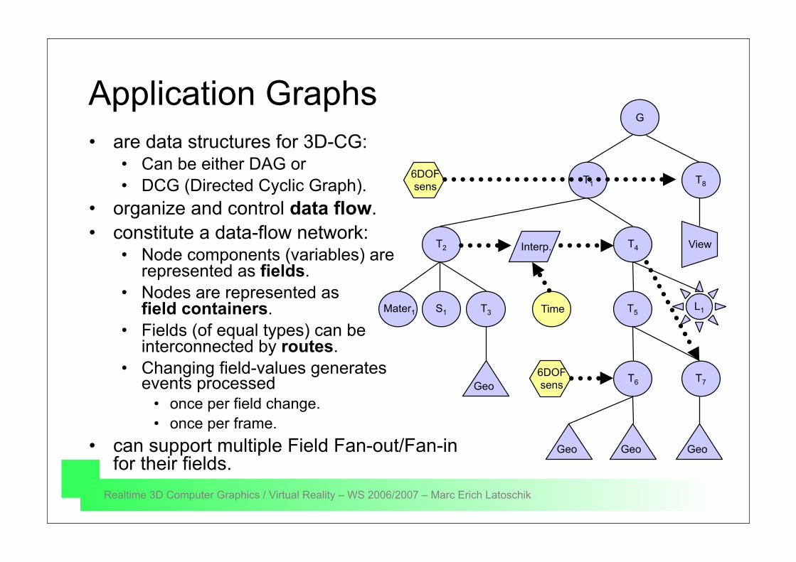
Application Graphs• are data structures for 3D-CG:
• Can be either DAG or • DCG (Directed Cyclic Graph).
• organize and control data flow.• constitute a data-flow network:
• Node components (variables) are represented as fields.
• Nodes are represented as field containers.
• Fields (of equal types) can be interconnected by routes.
• Changing field-values generates events processed
• once per field change.• once per frame.
• can support multiple Field Fan-out/Fan-infor their fields.
T8T1
T4
G
T2
T5
Geo
View
Mater1 S1 T3
GeoT6 T7
GeoGeo
L1
6DOFsens
6DOFsens
Interp.
Time

Realtime 3D Computer Graphics / Virtual Reality – WS 2006/2007 – Marc Erich Latoschik
A Scene Graph Language with Field Routing: VRML/X3D
#VRML V2.0 utf8Transform { translation -3 0 0 children Shape { geometry Box { } appearance Appearance { material Material { diffuseColor .8 .2 .2 } } }}Transform { translation 3 0 0 children Shape { geometry Cone { } appearance Appearance { material Material { diffuseColor .2 .2 .8 } } }}
More VRML later in this course!
Recommended