Real-life low power verification pitfalls,
and UPF 1801 for a CPF user
Paul Bailey STMicroelectronics UPD-DSMG R&D
DVclub 1st July 2013
Version 1.0
No part to be reproduced without permission from STMicroelectronics
Background
• I work in STMicroelectronics Unified Platform Division
• Consumer silicon and software => set-top box, TV, home-gateway, infotainment, …
• Leading low power silicon methodology and flow development across sites
• Based in Bristol, UK
• Includes multi-supply, multi-voltage (power islands) SoC design + verification
• Been taping-out large consumer SoCs with power islands 4+ years
• Were using CPF (Si2‟s Common Power Format)
• Now moving to IEEE UPF 1801
• This presentation:
• Collect and share some experience of low power verification pitfalls encountered
• Draws on real experiences of SoC teams in Bristol, Grenoble, Delhi, Bangalore.
• Share experience of moving CPF to UPF 1801
2
1. Multi-supply design and
functional verification pitfalls
Life is easy
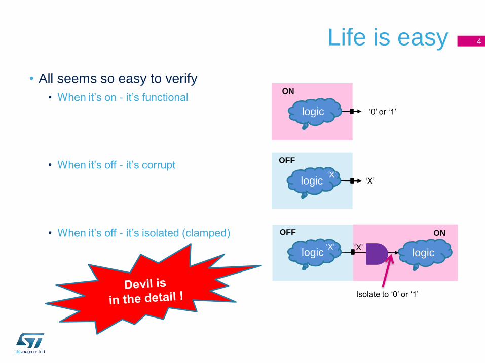
• All seems so easy to verify
• When it‟s on - it‟s functional
• When it‟s off - it‟s corrupt
• When it‟s off - it‟s isolated (clamped)
4
ON
logic „0‟ or „1‟
OFF
logic „X‟„X‟
logic
OFF
Isolate to „0‟ or „1‟
logic
ON
„X‟„X‟
Splendid isolation
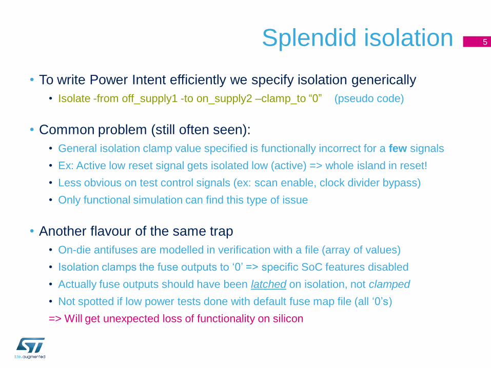
• To write Power Intent efficiently we specify isolation generically
• Isolate -from off_supply1 -to on_supply2 –clamp_to “0” (pseudo code)
• Common problem (still often seen):
• General isolation clamp value specified is functionally incorrect for a few signals
• Ex: Active low reset signal gets isolated low (active) => whole island in reset!
• Less obvious on test control signals (ex: scan enable, clock divider bypass)
• Only functional simulation can find this type of issue
• Another flavour of the same trap
• On-die antifuses are modelled in verification with a file (array of values)
• Isolation clamps the fuse outputs to „0‟ => specific SoC features disabled
• Actually fuse outputs should have been latched on isolation, not clamped
• Not spotted if low power tests done with default fuse map file (all „0‟s)
=> Will get unexpected loss of functionality on silicon
5
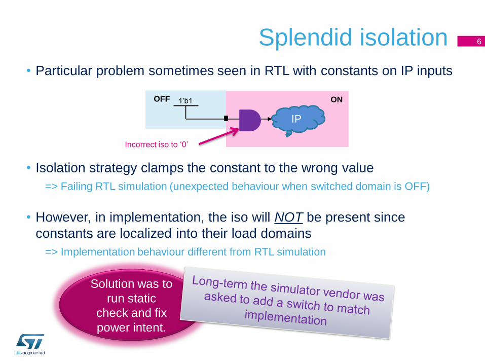
• Particular problem sometimes seen in RTL with constants on IP inputs
• Isolation strategy clamps the constant to the wrong value
=> Failing RTL simulation (unexpected behaviour when switched domain is OFF)
• However, in implementation, the iso will NOT be present since
constants are localized into their load domains
=> Implementation behaviour different from RTL simulation
IP
1‟b1OFF ON
Splendid isolation 6
Incorrect iso to „0‟
Solution was to
run static
check and fix
power intent.
Initially confusing
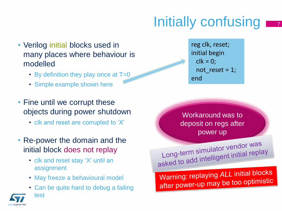
• Verilog initial blocks used in
many places where behaviour is
modelled
• By definition they play once at T=0
• Simple example shown here
• Fine until we corrupt these
objects during power shutdown
• clk and reset are corrupted to „X‟
• Re-power the domain and the
initial block does not replay
• clk and reset stay „X‟ until an
assignment
• May freeze a behavioural model
• Can be quite hard to debug a failing
test
7
reg clk, reset;initial begin
clk = 0;not_reset = 1;
end
Workaround was to
deposit on regs after
power up
Initially confusing
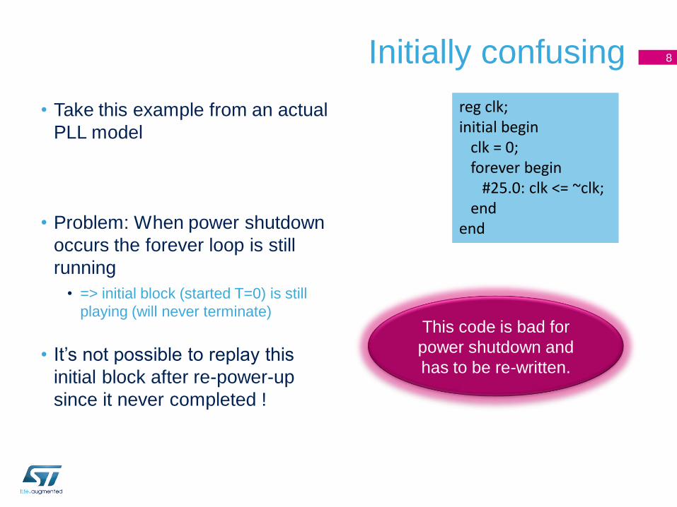
• Take this example from an actual
PLL model
• Problem: When power shutdown
occurs the forever loop is still
running
• => initial block (started T=0) is still
playing (will never terminate)
• It‟s not possible to replay this
initial block after re-power-up
since it never completed !
8
reg clk;initial begin
clk = 0;forever begin
#25.0: clk <= ~clk;end
end
This code is bad for
power shutdown and
has to be re-written.
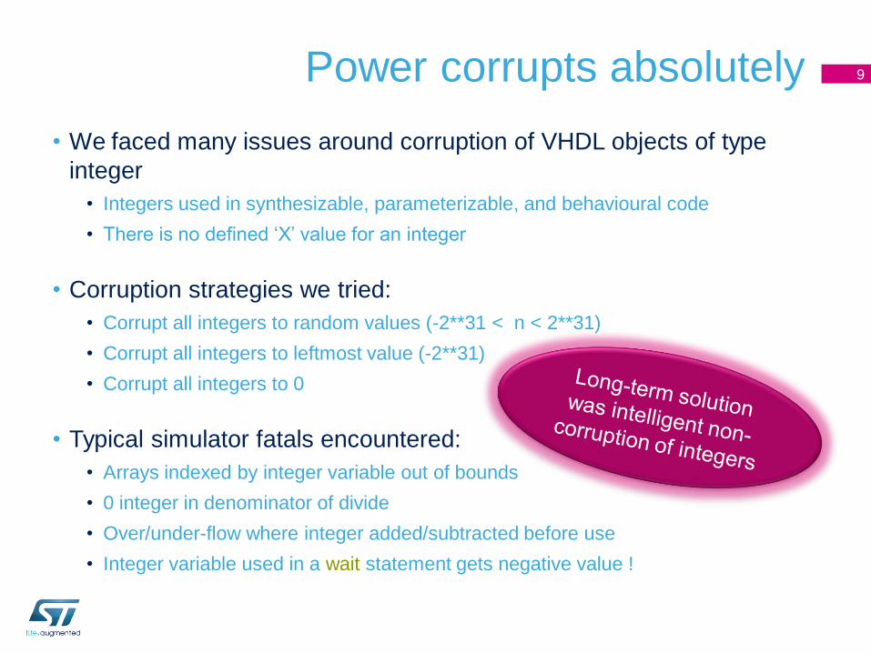
Power corrupts absolutely
• We faced many issues around corruption of VHDL objects of type
integer
• Integers used in synthesizable, parameterizable, and behavioural code
• There is no defined „X‟ value for an integer
• Corruption strategies we tried:
• Corrupt all integers to random values (-2**31 < n < 2**31)
• Corrupt all integers to leftmost value (-2**31)
• Corrupt all integers to 0
• Typical simulator fatals encountered:
• Arrays indexed by integer variable out of bounds
• 0 integer in denominator of divide
• Over/under-flow where integer added/subtracted before use
• Integer variable used in a wait statement gets negative value !
9
behav
codeconv_integer
Divide-
by-NN
OFF
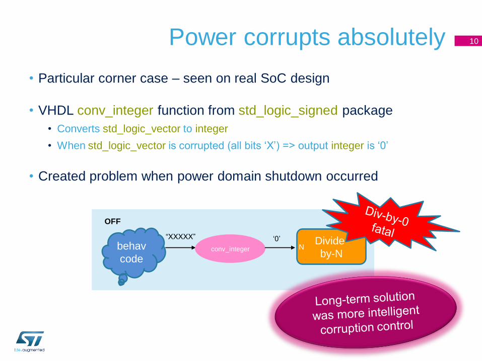
Power corrupts absolutely
• Particular corner case – seen on real SoC design
• VHDL conv_integer function from std_logic_signed package
• Converts std_logic_vector to integer
• When std_logic_vector is corrupted (all bits „X‟) => output integer is „0‟
• Created problem when power domain shutdown occurred
10
“XXXXX” „0‟
May the force be with you
• Simulation forces commonly used to workaround bad models or to
setup debug scenario
• In simulator we are using, power-off corruption „X‟ over-rides a user
force (we think correctly)
• Trouble is, at re-power-up forces don‟t come back
• Before we spotted this it caused significant wasted time debugging
code which worked ok, but then failed after a power down
11
2. Coming to UPF 1801 (aka
UPF 2.0) from CPF
Some reasons for the move
• Drivers for change included:• Only 1x EDA vendor‟ toolset supporting beyond CPF 1.0.e
• New tool step in our implementation flow only works with UPF
• Lack of supported CPF2UPF translation tools
• 3rd party IPs coming with complex UPF files – needed for verification
signoff
• Progressive convergence of CPF and UPF into IEEE 1801 standard
• First ST-UPD SoC project using UPF 1801 throughout is
underway now
• This presentation draws on our experience so far
13
Not all UPF tools are created equal• UPF 1801 LRM defines a large set of syntax, with complex semantics
• Design by committee (more so than CPF) => rich feature set
• EDA tool vendors have chosen to support what they judge is needed
by today‟s customers
• Consequence is each vendor/each tool supports different range of 1801 syntax
• First thing we did was do cross-vendor survey and construct a
subset of UPF 1801 which could be understood by
• Simulators (we considered at least 2)
• Static MV signoff tools (we considered at least 4)
• Implementation tools (we considered at least 4)
• Result was what we call “UPF 2.0 minus”
• Minus what is not supported across the mainstream industry tools today
• Defined a table of UPF commands + allowed arguments, to be used by designers
14
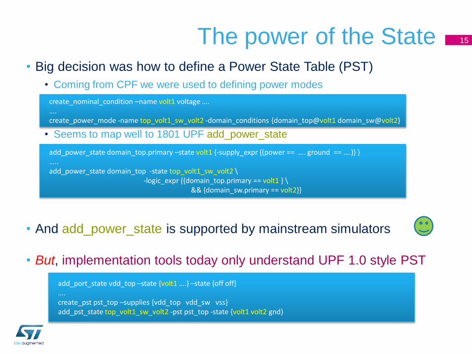
The power of the State• Big decision was how to define a Power State Table (PST)
• Coming from CPF we were used to defining power modes
• Seems to map well to 1801 UPF add_power_state
• And add_power_state is supported by mainstream simulators
• But, implementation tools today only understand UPF 1.0 style PST
15
create_nominal_condition –name volt1 voltage ….….create_power_mode -name top_volt1_sw_volt2 -domain_conditions {domain_top@volt1 domain_sw@volt2}
add_power_state domain_top.primary –state volt1 {-supply_expr {(power == …. ground == ….)} }…..add_power_state domain_top -state top_volt1_sw_volt2 \
-logic_expr {{domain_top.primary == volt1 } \&& {domain_sw.primary == volt2}}
add_port_state vdd_top –state {volt1 ….} –state {off off}….create_pst pst_top –supplies {vdd_top vdd_sw vss}add_pst_state top_volt1_sw_volt2 -pst pst_top -state {volt1 volt2 gnd}
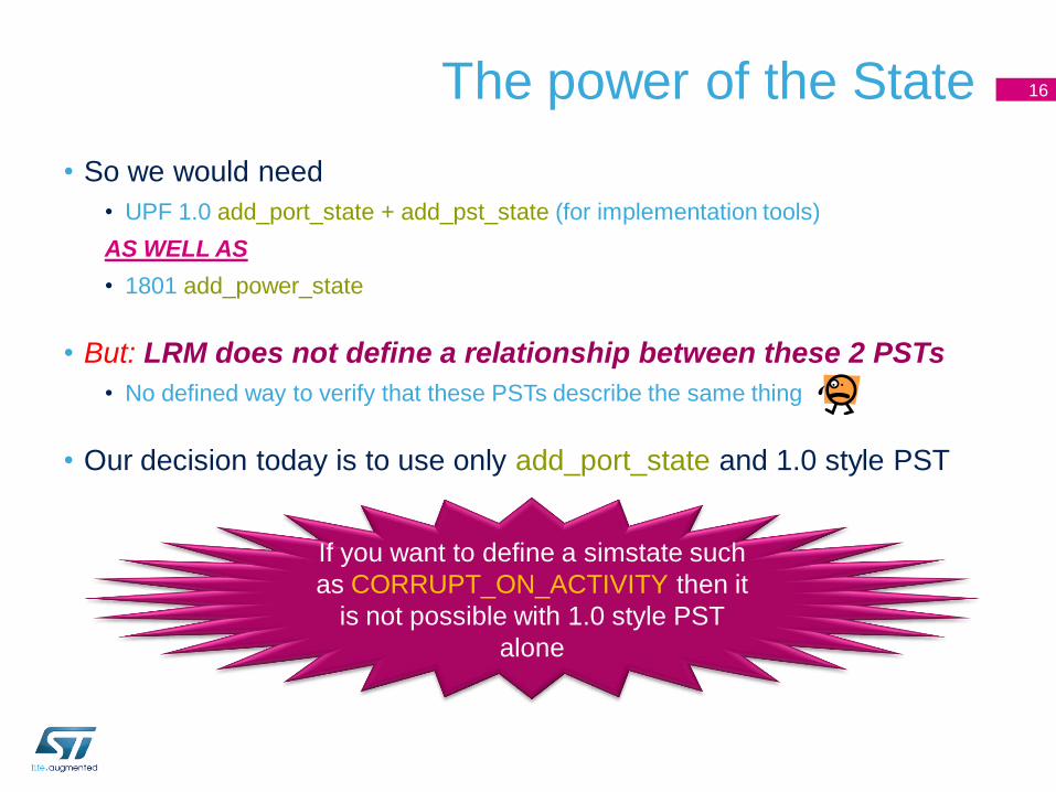
The power of the State
• So we would need
• UPF 1.0 add_port_state + add_pst_state (for implementation tools)
AS WELL AS
• 1801 add_power_state
• But: LRM does not define a relationship between these 2 PSTs
• No defined way to verify that these PSTs describe the same thing
• Our decision today is to use only add_port_state and 1.0 style PST
16
If you want to define a simstate such
as CORRUPT_ON_ACTIVITY then it
is not possible with 1.0 style PST
alone
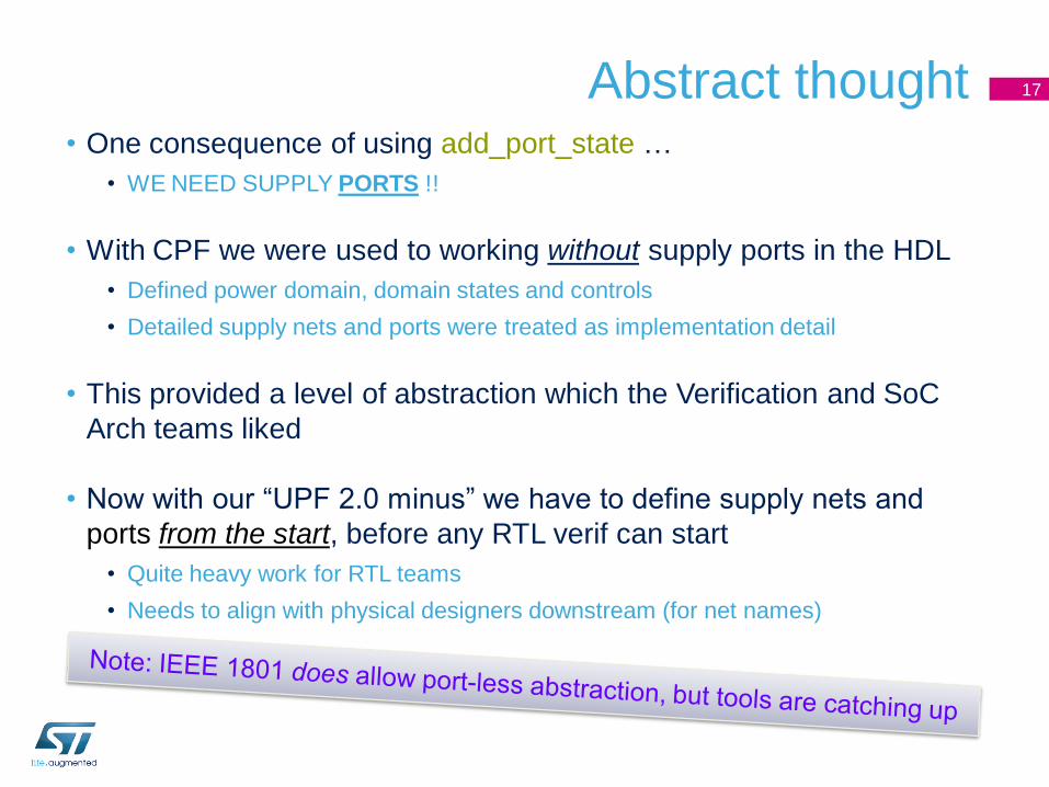
Abstract thought• One consequence of using add_port_state …
• WE NEED SUPPLY PORTS !!
• With CPF we were used to working without supply ports in the HDL
• Defined power domain, domain states and controls
• Detailed supply nets and ports were treated as implementation detail
• This provided a level of abstraction which the Verification and SoC
Arch teams liked
• Now with our “UPF 2.0 minus” we have to define supply nets and
ports from the start, before any RTL verif can start
• Quite heavy work for RTL teams
• Needs to align with physical designers downstream (for net names)
17
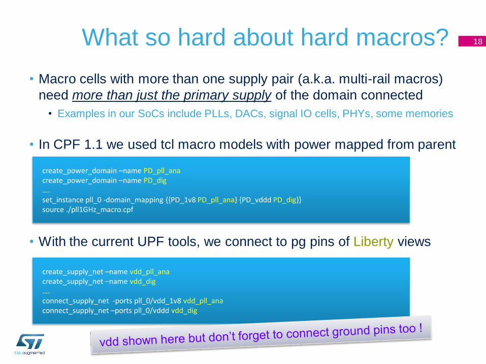
What so hard about hard macros?
• Macro cells with more than one supply pair (a.k.a. multi-rail macros)
need more than just the primary supply of the domain connected
• Examples in our SoCs include PLLs, DACs, signal IO cells, PHYs, some memories
• In CPF 1.1 we used tcl macro models with power mapped from parent
• With the current UPF tools, we connect to pg pins of Liberty views
18
create_power_domain –name PD_pll_anacreate_power_domain –name PD_dig….set_instance pll_0 -domain_mapping {{PD_1v8 PD_pll_ana} {PD_vddd PD_dig}}source ./pll1GHz_macro.cpf
create_supply_net –name vdd_pll_anacreate_supply_net –name vdd_dig….connect_supply_net -ports pll_0/vdd_1v8 vdd_pll_anaconnect_supply_net –ports pll_0/vddd vdd_dig
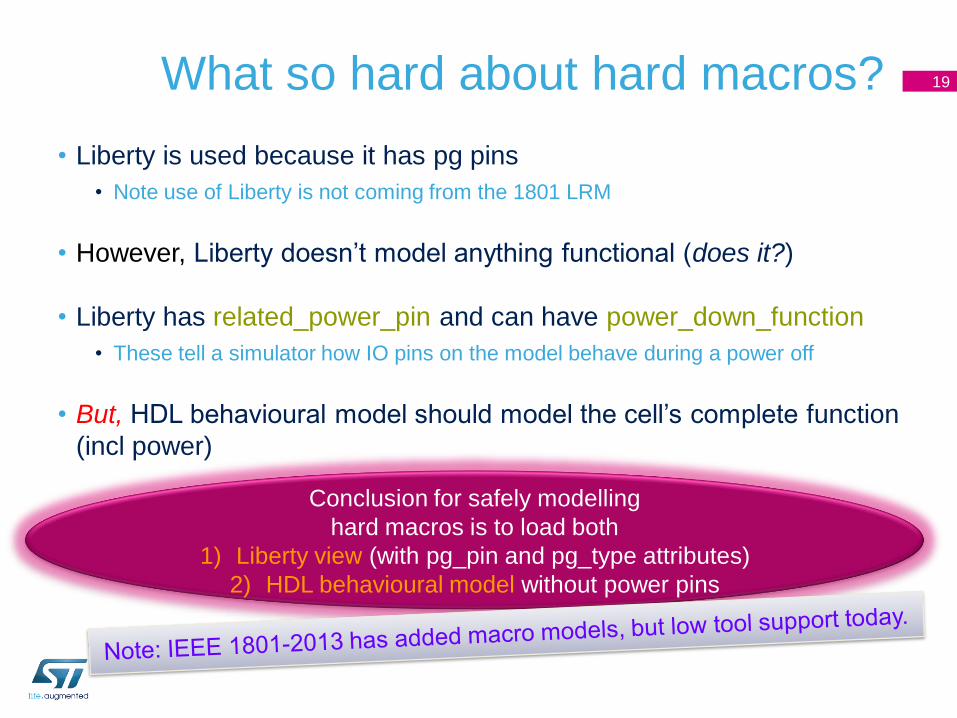
What so hard about hard macros?
• Liberty is used because it has pg pins
• Note use of Liberty is not coming from the 1801 LRM
• However, Liberty doesn‟t model anything functional (does it?)
• Liberty has related_power_pin and can have power_down_function
• These tell a simulator how IO pins on the model behave during a power off
• But, HDL behavioural model should model the cell‟s complete function
(incl power)
19
Conclusion for safely modelling
hard macros is to load both
1) Liberty view (with pg_pin and pg_type attributes)
2) HDL behavioural model without power pins
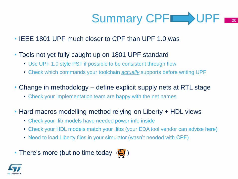
Summary CPF UPF
• IEEE 1801 UPF much closer to CPF than UPF 1.0 was
• Tools not yet fully caught up on 1801 UPF standard
• Use UPF 1.0 style PST if possible to be consistent through flow
• Check which commands your toolchain actually supports before writing UPF
• Change in methodology – define explicit supply nets at RTL stage
• Check your implementation team are happy with the net names
• Hard macros modelling method relying on Liberty + HDL views
• Check your .lib models have needed power info inside
• Check your HDL models match your .libs (your EDA tool vendor can advise here)
• Need to load Liberty files in your simulator (wasn‟t needed with CPF)
• There‟s more (but no time today )
20

Thank you
Recommended