N° di serie S/N
Manufacturing year
2016
Type
RB-DV
Operating and maintenance instructions for blowers.
Instruction for
Transport | Installation | Operation | Maintenance
PD Blower & Vacuum Pump Service & Repair Facility 120 – 10293 276 ST, Acheson, Alberta, Canada T7X 6A5
T: 780.962.1827 F: 780.962.1830 E: [email protected]
3
GENERAL INFORMATION
This manual is integral part of the machine follow strictly the instructions given in this Manual prior to positioning and operating the blower. For a quick and rational reading of this manual observe the following statements and definitions :
Warning : Signals the risk of serious physical dangers to people and/or serious danger to blower
Note : Signals important technical information for the operation of the blower
Qualified personnel It means these persons who, on account of their training, experience and instruction and their knowledge of relevant standards, specifications, accident prevention rules and operating conditions, have been authorized by those responsible for the safety of the plant to carry out the necessary work on the blower and who can recognize and avoid any possible dangers.
Acknowledge of first aid is also required as is information about local rescue facilities.
The blower is a rotary lobe compressor suitable only for industrial use as described in this Manual. Any other use is to be considered improper and is therefore forbidden.
The blower must be installed in a safe area, accessible only by qualified personnel .
Warning : Non-qualified personnel are not permitted to work on or near the blower
The personnel in charge must be well acquainted with this Manual, and then conserve carefully the Manual in a known site in order that it is available for future consultations.
The maintenance operations are to be carried out by qualified personnel following the instructions given in this Manual and using only original spare parts.
www.fraserwoods.ca
4
SAFETY INFORMATION
Delivery of ROBUSCHI does not include the design of the operating environment where the blower will be installed, nor the power circuits, control circuits and other controls or equipments required by the specific function of the blower. The CUSTOMER therefore must verify that the operating environment, the power circuits, the control circuits and the other controls or equipments related to the function of the blower satisfy the essential safety requirements of the European Machinery Directive 89/392/EEC and/or of the corresponding legislation of the country where the blower is used. The CUSTOMER must also ensure that the valid legislation on eletric safety (Low-Voltage Directive) and Electromagnetic Compatibility of equipment (EMC Directive) is followed.
Warning : All the personnel that come in contact with the blower must observe following safety regulations
During Blower operation Do not touch external surfaces of the blower and of the outlet silencer : surfaces temperature above 70 °C. Do not open oil plugs during operation. Do not disassemble transmission guard. Do not approach blower without suitable clothing (avoid large clothes, neckties, bracelets or necklaces).
Do not use the blower in operating conditions different from the ones rated in the order confirmation. Do not touch components under electric supply. Dispose of fire-fighting equipment close to the blower
Before an y staff service on the Blower Stop the blower and auxiliary systems as described at par. 5.4
Warning : Disconnect the electric supply, lock the general switching open position with the key and conserve it during the service operation
Warning : Insulate the blower from the plant and restore the atmospheric pressure into it.
Warning : The gas contained in the plant may be hot, toxic and irritant
Warning : Wait until the blower returns at the ambient temperature (< 40°C)
During staff service on the blower Check that all the operations indicated above have been completed. Lift the blower and the main piping by a suitable equipment only. During cleaning operations involving the use of sprays or cleaning agents special attention is to be paid to relevant user information to avoid the poisoning due to fumes or burns due to caustic substances.
Warning : Do not use non-original spare parts or accesssories .
Note : ROBUSCHI will not be liable for any damage, brealdown, injury deriving from
the use of non-original spare parts or accessories
www.fraserwoods.ca
5
BLOWER IDENTIFICATION
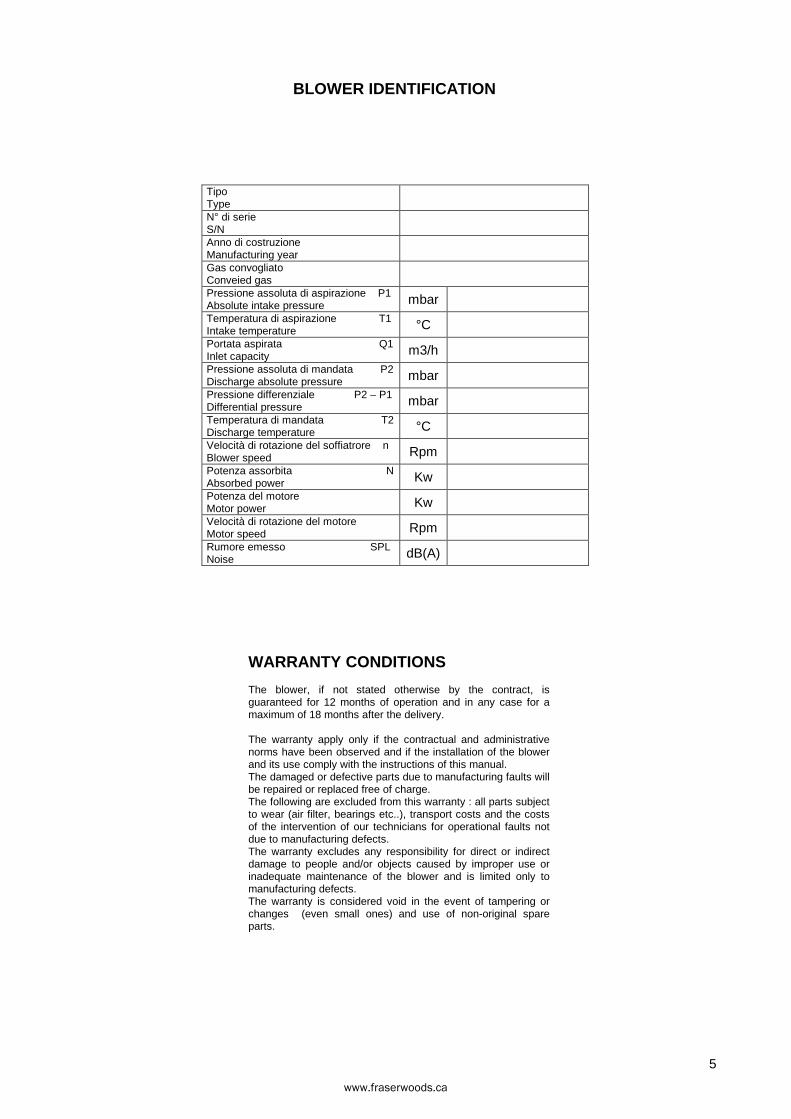
Tipo Type N° di serie S/N Anno di costruzione Manufacturing year Gas convogliato Conveied gas Pressione assoluta di aspirazione P1 Absolute intake pressure mbar Temperatura di aspirazione T1 Intake temperature °C Portata aspirata Q1 Inlet capacity m3/h Pressione assoluta di mandata P2 Discharge absolute pressure mbar Pressione differenziale P2 – P1 Differential pressure mbar Temperatura di mandata T2 Discharge temperature °C Velocità di rotazione del soffiatrore n Blower speed Rpm Potenza assorbita N Absorbed power Kw Potenza del motore Motor power Kw Velocità di rotazione del motore Motor speed Rpm Rumore emesso SPL Noise dB(A)
WARRANTY CONDITIONS
The blower, if not stated otherwise by the contract, is guaranteed for 12 months of operation and in any case for a maximum of 18 months after the delivery.
The warranty apply only if the contractual and administrative norms have been observed and if the installation of the blower and its use comply with the instructions of this manual. The damaged or defective parts due to manufacturing faults will be repaired or replaced free of charge. The following are excluded from this warranty : all parts subject to wear (air filter, bearings etc..), transport costs and the costs of the intervention of our technicians for operational faults not due to manufacturing defects. The warranty excludes any responsibility for direct or indirect damage to people and/or objects caused by improper use or inadequate maintenance of the blower and is limited only to manufacturing defects. The warranty is considered void in the event of tampering or changes (even small ones) and use of non-original spare parts.
www.fraserwoods.ca
22
INDEX
1 BLOWER CHARACTERISTICS ............................................................................................... 22 1.1 Operating principle .............................................................................................................. 22 1.2 Construction ........................................................................................................................ 22 1.3 Nameplate ........................................................................................................................... 22
2 PERFORMANCE LIMITS AND WORKING CONDITIONS ..................................................... 23 2.1 Operating environment and conveyed gas .......................................................................... 23 2.2 Performance limits .............................................................................................................. 23 2.3 Flow adjustment .................................................................................................................. 23 2.4 Noise level ........................................................................................................................... 23 2.5 Forbidden uses.................................................................................................................... 24 2.6 Residual risks ...................................................................................................................... 24
3 STORAGE ................................................................................................................................ 25 3.1 Unpacking ........................................................................................................................... 25 3.2 Handling .............................................................................................................................. 25 3.3 Preservation ........................................................................................................................ 25
4 INSTALLATION ........................................................................................................................ 26 4.1 On-site positioning of blower ............................................................................................... 26 4.2 Changing the inlet/outlet arrangement ................................................................................ 26 4.3 Direction of rotation – Gas flow direction ............................................................................ 26 4.4 Coupling .............................................................................................................................. 27
4.4.1 Direct coupling ............................................................................................................ 27 4.4.2 Belt drive coupling ...................................................................................................... 28
4.5 System piping ...................................................................................................................... 29 4.5.1 Vacuum operation ...................................................................................................... 29 4.5.2 Pressure operation ..................................................................................................... 29 4.5.3 Pressure / Vacuum operation ..................................................................................... 29
4.6 Cooling circuit (only for /RV) ................................................................................................ 30 4.7 Electric connection .............................................................................................................. 30
5 OPERATION ............................................................................................................................. 31 5.1 Preliminary controls ............................................................................................................. 31 5.2 First start up ........................................................................................................................ 31 5.3 Operation ............................................................................................................................. 31 5.4 Stopping the blower ............................................................................................................. 31
6 MAINTENANCE ....................................................................................................................... 32 6.1 Oil change ........................................................................................................................... 32
6.1.1 Oil type and viscosity .................................................................................................. 32 6.1.2 Recommended mineral oils ........................................................................................ 32
6.2 Replacing the shaft seal ...................................................................................................... 33 6.3 Cleaning compression chamber.......................................................................................... 33 6.4 Check of the gear clearance ............................................................................................... 33 6.5 Check of the rotors clearance ............................................................................................. 33 6.6 Spare parts .......................................................................................................................... 34 6.7 Demolition of the blower ...................................................................................................... 34
7 TROUBLESHOOTING ............................................................................................................. 35
8 DISASSEMBLY AND REASSEMBLY ..................................................................................... 36 8.1 Disassembly ........................................................................................................................ 36
8.1.2 Disassembly of drive side sump ................................................................................. 36 8.1.3 Disassembly of gear side sump.................................................................................. 36
8.2 Reassembly ......................................................................................................................... 36 8.2.1 Reassembly of drive side sump .................................................................................. 36 8.2.2 Reassembly of gear side sump .................................................................................. 36
www.fraserwoods.ca
23
1 BLOWER CHARACTERISTICS
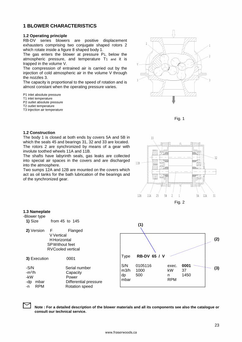
1.2 Operating principle RB-DV series blowers are positive displacement exhausters comprising two conjugate shaped rotors 2 which rotate inside a figure 8 shaped body 1. The gas enters the blower at pressure P1, below the atmospheric pressure, and temperature T1 and it is trapped in the volume V. The compression of entrained air is carried out by the injection of cold atmospheric air in the volume V through the nozzles 3. The capacity is proportional to the speed of rotation and is almost constant when the operating pressure varies.
P1 inlet absolute pressure T1 inlet temperature P2 outlet absolute pressure T2 outlet temperature T3 injection air temperature
Fig. 1
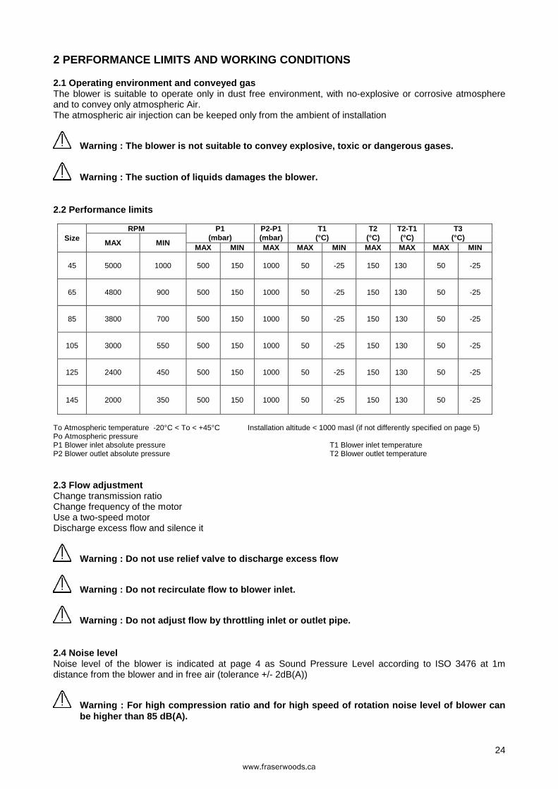
1.2 Construction The body 1 is closed at both ends by covers 5A and 5B in which the seals 45 and bearings 31, 32 and 33 are located. The rotors 2 are synchronized by means of a gear with involute toothed wheels 11A and 11B. The shafts have labyrinth seals, gas leaks are collected into special air spaces in the covers and are discharged into the atmosphere. Two sumps 12A and 12B are mounted on the covers which act as oil tanks for the bath lubrication of the bearings and of the synchronized gear.
Fig. 2
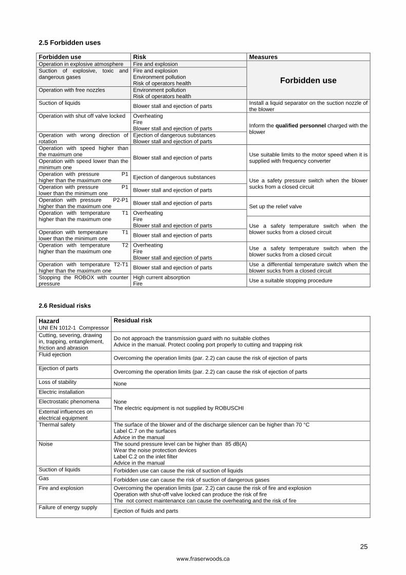
1.3 Nameplate -Blower type
1) Size from 45 to 145
2) Version F Flanged V Vertical
H Horizontal SP Without feet RV Cooled vertical
3) Execution 0001
-S/N Serial number -m3/h Capacity -kW Power -dp mbar Differential pressure -n RPM Rotation speed
Note : For a detailed description of the blower mate rials and all its components see also the catalogue or consult our technical service.
Type RB-DV 65 / V
S/N 0105116 exec. 0001 m3/h 1000 kW 37 dp 500 n 1450 mbar RPM
(3)
(1)
(2)
12
33
11B
12B
32
3112A5A5B2511A
3 3
2
V
2
1
www.fraserwoods.ca
24
2 PERFORMANCE LIMITS AND WORKING CONDITIONS
2.1 Operating environment and conveyed gas The blower is suitable to operate only in dust free environment, with no-explosive or corrosive atmosphere and to convey only atmospheric Air. The atmospheric air injection can be keeped only from the ambient of installation
Warning : The blower is not suitable to convey explo sive, toxic or dangerous gases.
Warning : The suction of liquids damages the blower.
2.2 Performance limits
Size RPM P1
(mbar) P2-P1 (mbar)
T1 (°C)
T2 (°C)
T2-T1 (°C)
T3 (°C)
MAX MIN MAX MIN MAX MAX MIN MAX MAX MAX MIN
45 5000 1000 500 150 1000 50 -25 150 130 50 -25
65 4800 900 500 150 1000 50 -25 150 130 50 -25
85 3800 700 500 150 1000 50 -25 150 130 50 -25
105 3000 550 500 150 1000 50 -25 150 130 50 -25
125 2400 450 500 150 1000 50 -25 150 130 50 -25
145 2000 350 500 150 1000 50 -25 150 130 50 -25
To Atmospheric temperature -20°C < To < +45°C Installation altitude < 1000 masl (if not differently specified on page 5) Po Atmospheric pressure P1 Blower inlet absolute pressure T1 Blower inlet temperature P2 Blower outlet absolute pressure T2 Blower outlet temperature
2.3 Flow adjustment Change transmission ratio Change frequency of the motor Use a two-speed motor Discharge excess flow and silence it
Warning : Do not use relief valve to discharge exces s flow
Warning : Do not recirculate flow to blower inlet.
Warning : Do not adjust flow by throttling inlet or outlet pipe.
2.4 Noise level Noise level of the blower is indicated at page 4 as Sound Pressure Level according to ISO 3476 at 1m distance from the blower and in free air (tolerance +/- 2dB(A))
Warning : For high compression ratio and for high sp eed of rotation noise level of blower can be higher than 85 dB(A).
www.fraserwoods.ca
25
2.5 Forbidden uses
Forbidden use Risk Measures Operation in explosive atmosphere Fire and explosion
Forbidden use Suction of explosive, toxic and dangerous gases
Fire and explosion Environment pollution Risk of operators health
Operation with free nozzles Environment pollution Risk of operators health
Suction of liquids Blower stall and ejection of parts Install a liquid separator on the suction nozzle of the blower
Operation with shut off valve locked Overheating Fire Blower stall and ejection of parts Inform the qualified personnel charged with the
blower Operation with wrong direction of rotation
Ejection of dangerous substances Blower stall and ejection of parts
Operation with speed higher than the maximum one
Blower stall and ejection of parts Use suitable limits to the motor speed when it is supplied with frequency converter Operation with speed lower than the
minimum one Operation with pressure P1 higher than the maximum one
Ejection of dangerous substances Use a safety pressure switch when the blower sucks from a closed circuit Operation with pressure P1
lower than the minimum one Blower stall and ejection of parts
Operation with pressure P2-P1 higher than the maximum one
Blower stall and ejection of parts Set up the relief valve
Operation with temperature T1 higher than the maximum one
Overheating Fire Blower stall and ejection of parts Use a safety temperature switch when the
blower sucks from a closed circuit Operation with temperature T1 lower than the minimum one
Blower stall and ejection of parts
Operation with temperature T2 higher than the maximum one
Overheating Fire Blower stall and ejection of parts
Use a safety temperature switch when the blower sucks from a closed circuit
Operation with temperature T2-T1 higher than the maximum one
Blower stall and ejection of parts Use a differential temperature switch when the blower sucks from a closed circuit
Stopping the ROBOX with counter pressure
High current absorption Fire
Use a suitable stopping procedure
2.6 Residual risks
Hazard UNI EN 1012-1 Compressor
Residual risk
Cutting, severing, drawing in, trapping, entanglement, friction and abrasion
Do not approach the transmission guard with no suitable clothes Advice in the manual. Protect cooling port properly to cutting and trapping risk
Fluid ejection Overcoming the operation limits (par. 2.2) can cause the risk of ejection of parts
Ejection of parts Overcoming the operation limits (par. 2.2) can cause the risk of ejection of parts
Loss of stability None
Electric installation
None The electric equipment is not supplied by ROBUSCHI
Electrostatic phenomena
External influences on electrical equipment Thermal safety The surface of the blower and of the discharge silencer can be higher than 70 °C
Label C.7 on the surfaces Advice in the manual
Noise The sound pressure level can be higher than 85 dB(A) Wear the noise protection devices Label C.2 on the inlet filter Advice in the manual
Suction of liquids Forbidden use can cause the risk of suction of liquids Gas Forbidden use can cause the risk of suction of dangerous gases
Fire and explosion Overcoming the operation limits (par. 2.2) can cause the risk of fire and explosion Operation with shut-off valve locked can produce the risk of fire The not correct maintenance can cause the overheating and the risk of fire
Failure of energy supply Ejection of fluids and parts
www.fraserwoods.ca
26
3 STORAGE
3.1 Unpacking Check always the correspondence between documents and materials and the presence of eventual damages due to transport.
Warning: Remove with care the packing and clearing a ll the dangerous elements (nails, splits, etc…)
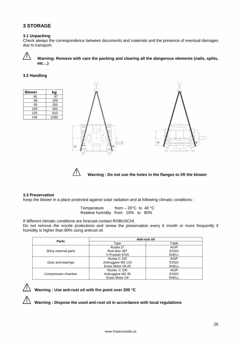
3.2 Handling
Blower kg 45 97 65 159 85 250
105 400 125 610 145 1099
Warning : Do not use the holes in the flanges to lif t the blower
3.3 Preservation Keep the blower in a place protected against solar radiation and at following climatic conditions :
Temperature from – 20°C to 40 °C Relative humidity from 10% to 80%
If different climatic conditions are forecast contact ROBUSCHI. Do not remove the nozzle protections and renew the preservation every 6 month or more frequently if humidity is higher than 80% using antirust oil.
Parts Anti-rust oil
Type Trade
Shiny external parts Rustia 27
Rust Ban 397 V-Produkt 9703
AGIP ESSO SHELL
Gear and bearings Rustia C 100
Antiruggine MZ 110 Ensis Motor Oil 20
AGIP ESSO SHELL
Compression chamber Rustia C 100
Antiruggine MZ 45 Ensis Motor Oil
AGIP ESSO SHELL
Warning : Use anti-rust oil with fire point over 200 °C
Warning : Dispose the used anti-rust oil in accordan ce with local regulations
www.fraserwoods.ca
27
4 INSTALLATION
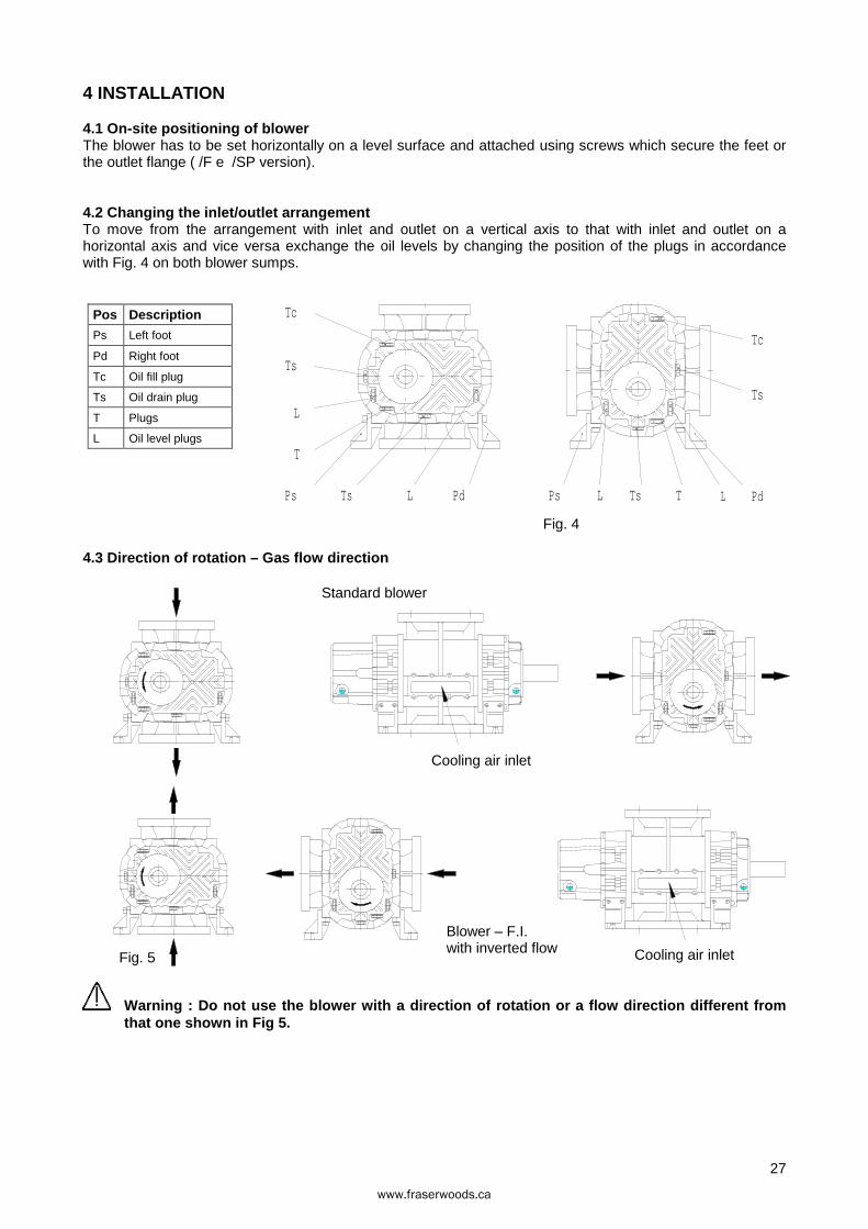
4.1 On-site positioning of blower The blower has to be set horizontally on a level surface and attached using screws which secure the feet or the outlet flange ( /F e /SP version).
4.2 Changing the inlet/outlet arrangement To move from the arrangement with inlet and outlet on a vertical axis to that with inlet and outlet on a horizontal axis and vice versa exchange the oil levels by changing the position of the plugs in accordance with Fig. 4 on both blower sumps.
Pos Description
Ps Left foot
Pd Right foot
Tc Oil fill plug
Ts Oil drain plug
T Plugs
L Oil level plugs
Fig. 4
4.3 Direction of rotation – Gas flow direction
Fig. 5
Warning : Do not use the blower with a direction of rotation or a flow direction different from that one shown in Fig 5.
Tc
Ts
PdLTTsLPsL PdTsPs
T
L
Ts
Tc
Standard blower
Cooling air inlet
Blower – F.I. with inverted flow Cooling air inlet
www.fraserwoods.ca
28
4.4 Coupling
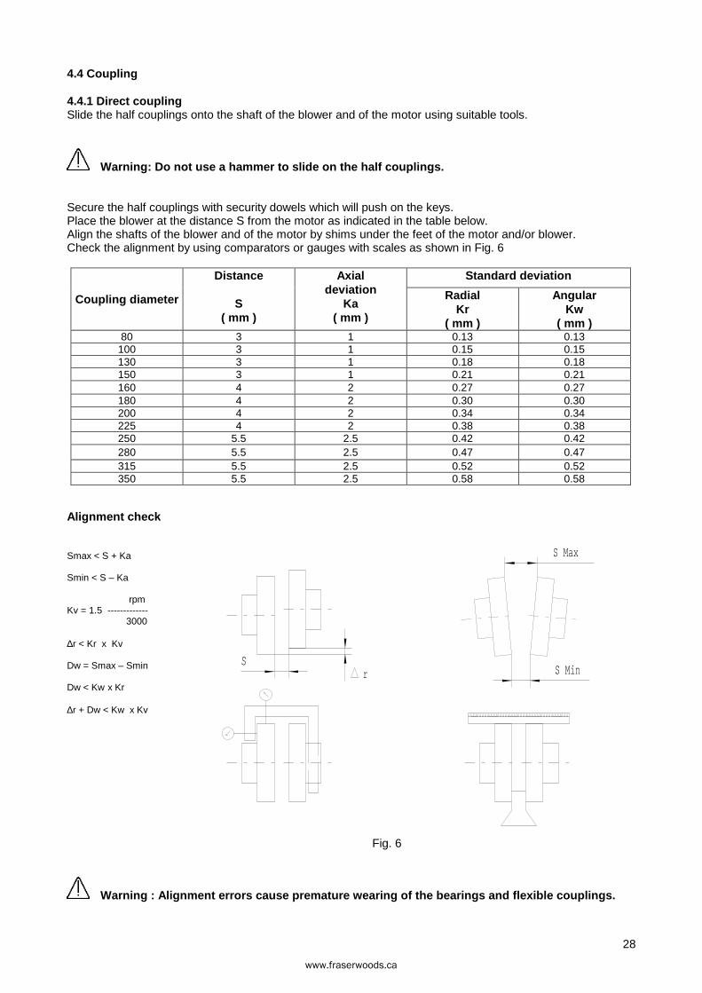
4.4.1 Direct coupling Slide the half couplings onto the shaft of the blower and of the motor using suitable tools.
Warning: Do not use a hammer to slide on the half co uplings.
Secure the half couplings with security dowels which will push on the keys. Place the blower at the distance S from the motor as indicated in the table below. Align the shafts of the blower and of the motor by shims under the feet of the motor and/or blower. Check the alignment by using comparators or gauges with scales as shown in Fig. 6
Coupling diameter
Distance
S ( mm )
Axial deviation
Ka ( mm )
Standard deviation
Radial Kr
( mm )
Angular Kw
( mm ) 80 3 1 0.13 0.13
100 3 1 0.15 0.15 130 3 1 0.18 0.18 150 3 1 0.21 0.21 160 4 2 0.27 0.27 180 4 2 0.30 0.30 200 4 2 0.34 0.34 225 4 2 0.38 0.38 250 5.5 2.5 0.42 0.42 280 5.5 2.5 0.47 0.47 315 5.5 2.5 0.52 0.52 350 5.5 2.5 0.58 0.58
Alignment check
Smax < S + Ka
Smin < S – Ka
rpm Kv = 1.5 -------------
3000
∆r < Kr x Kv
Dw = Smax – Smin
Dw < Kw x Kr
∆r + Dw < Kw x Kv
Fig. 6
Warning : Alignment errors cause premature wearing o f the bearings and flexible couplings.
rS
S Max
S Min
www.fraserwoods.ca
29
4.4.2 Belt drive coupling Utilize pulleys with minimum diameter equal or major than the value indicated in the table below.
Warning : Do not use a hammer to mount the pulleys.
Use suitable equipment to mount the pulleys onto the blower and motor shafts.
Minimum allowed blower pulley pitch diameter
Size Differential pressure ( mbar )
200 300 400 500 600 700 800 900 1000 45 80 80 80 90 100 106 112 118 125 65 80 80 80 90 100 106 112 118 125 85 100 106 112 118 125 132 140 150 160
105 112 118 125 132 140 150 160 180 200 125 118 125 132 140 150 160 180 200 225 145 125 132 140 150 160 180 200 225 250
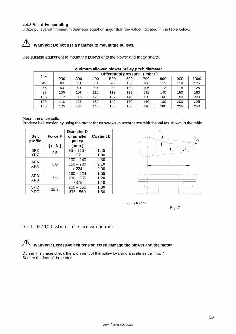
Mount the drive belts Produce belt tension by using the motor thrust screws in accordance with the values shown in the table
Belt profile
Force F
[ daN ]
Diameter D of smaller
pulley [ mm ]
Costant E
SPZ XPZ
2.5 95 – 125> 132
1.45 1.30
SPA XPA 5.0
100 – 140 150 – 200
> 224
2.30 2.10 2.00
SPB XPB 7.5
160 – 224 236 – 355
> 375
1.55 1.20 1.10
SPC XPC
12.5 250 – 355 375 - 560
1.80 1.60
e = I x E / 100 Fig. 7
e = I x E / 100, where I is expressed in mm
Warning : Excessive belt tension could damage the blower and the motor
During this phase check the alignment of the pulley by using a scale as per Fig. 7 Secure the feet of the motor
e
F
I
Dp
www.fraserwoods.ca
30
4.5 System piping The diameters of the system piping must be chosen in order to obtain an average gas speed from 15 a 30 m/s and must never be smaller than the diameters of the blower openings, if the diameters are different, use a taper connector. The system piping should be properly aligned and supported to prevent stress on the blower openings Connect the cooling ports to atmosphere by means of silenced pipings.
Warning:protect consistently the cooling port from the risk of cutting and trapping.
Provide flexible joints and support the pipes near the nozzles. Isolate the pipes to avoid heating the environment as well as a precaution to accidental contact The pipes must be thoroughly cleaned before connection, in case of vacuum operation install a dirt filter for the first 100 working hours and provide a vacuometer to check the dirt filter. The gaskets must not interfere with the gas system.
Warning : Remove the protective covers from the blow er openings just before connection.
Warning: The surface of the delivery pipes can exceed 70 °C.
The recommended accessories are the following
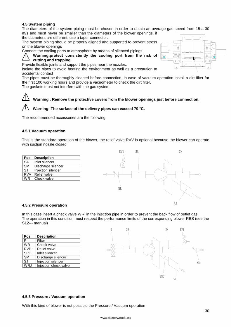
4.5.1 Vacuum operation
This is the standard operation of the blower, the relief valve RVV is optional because the blower can operate with suction nozzle closed
Pos. Description SA Inlet silencer SM Discharge silencer SJ Injection silencer RVV Relief valve WR Check valve
4.5.2 Pressure operation
In this case insert a check valve WRi in the injection pipe in order to prevent the back flow of outlet gas. The operation in this condition must respect the performance limits of the corresponding blower RBS (see the S12--- manual)
Pos. Description F Filter WR Check valve RVP Relief valve SPF Inlet silencer SM Discharge silencer SJ Injection silencer WRJ Injection check valve
4.5.3 Pressure / Vacuum operation
With this kind of blower is not possible the Pressure / Vacuum operation
WR
SA SMRVV
SJ
SJ
RVPSMSAF
WR
WRJ
www.fraserwoods.ca
31
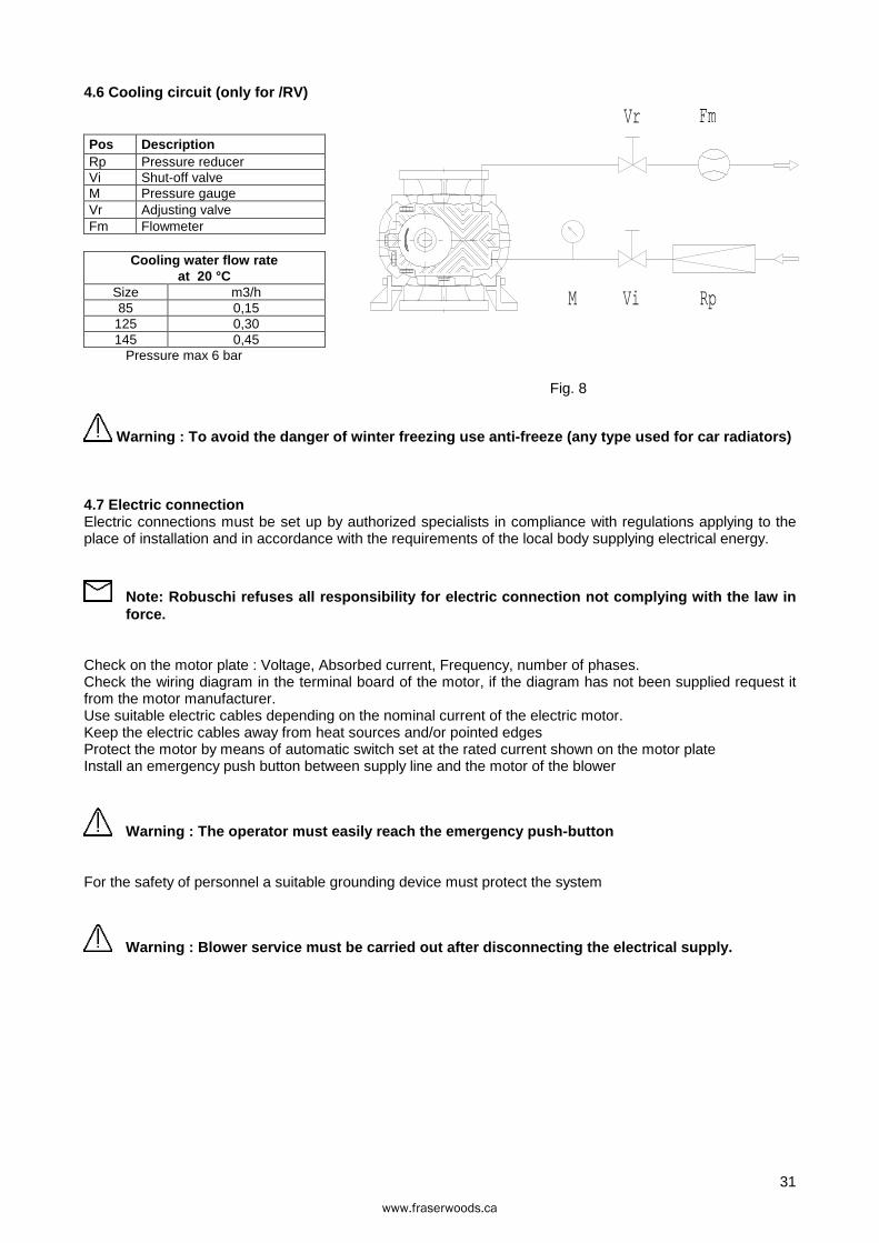
4.6 Cooling circuit (only for /RV)
Pos Description Rp Pressure reducer Vi Shut-off valve M Pressure gauge Vr Adjusting valve Fm Flowmeter
Cooling water flow rate at 20 °C
Size m3/h 85 0,15
125 0,30 145 0,45
Pressure max 6 bar
Fig. 8
Warning : To avoid the danger of winter freezing use anti-freeze (any type used for car radiators)
4.7 Electric connection Electric connections must be set up by authorized specialists in compliance with regulations applying to the place of installation and in accordance with the requirements of the local body supplying electrical energy.
Note: Robuschi refuses all responsibility for electr ic connection not complying with the law in force.
Check on the motor plate : Voltage, Absorbed current, Frequency, number of phases. Check the wiring diagram in the terminal board of the motor, if the diagram has not been supplied request it from the motor manufacturer. Use suitable electric cables depending on the nominal current of the electric motor. Keep the electric cables away from heat sources and/or pointed edges Protect the motor by means of automatic switch set at the rated current shown on the motor plate Install an emergency push button between supply line and the motor of the blower
Warning : The operator must easily reach the emergen cy push-button
For the safety of personnel a suitable grounding device must protect the system
Warning : Blower service must be carried out after d isconnecting the electrical supply.
FmVr
Vi RpM
www.fraserwoods.ca
32
5 OPERATION
5.1 Preliminary controls If the blower has been in storage for more than 6 months, check its state of preservation. Check the alignment of the transmission and eventually the belt tension . Check that the blower rotate freely by hand. Check that the safety protection devices have been correctly installed and secured. Check that the pipes have been internally cleaned and if eventually obstructions have been removed. Check that all connections between pipes and blower are tightened and sealed. Fill the blower with oil as described in paragraph 6.1
5.2 First start up
Warning : The personnel must wear the noise protecti on devices.
Open the shut-off valves on the piping. Check that the relief valve has been set at the operating value. Check the rotation direction using a short current pulse.
Warning : Do not rotate the blower in the wrong dire ction for more than a few revolution.
Open the valve of the cooling circuit (only for /RV)
Start the blower.
Increase the operating pressure gradually until the rated value is reached. During the first 8 hours of operation check that there are no oil leakage, no cooling liquid leakage (only /RV) and strange noises or vibrations, if such problems are found stop the blower immediately and contact our PV service.
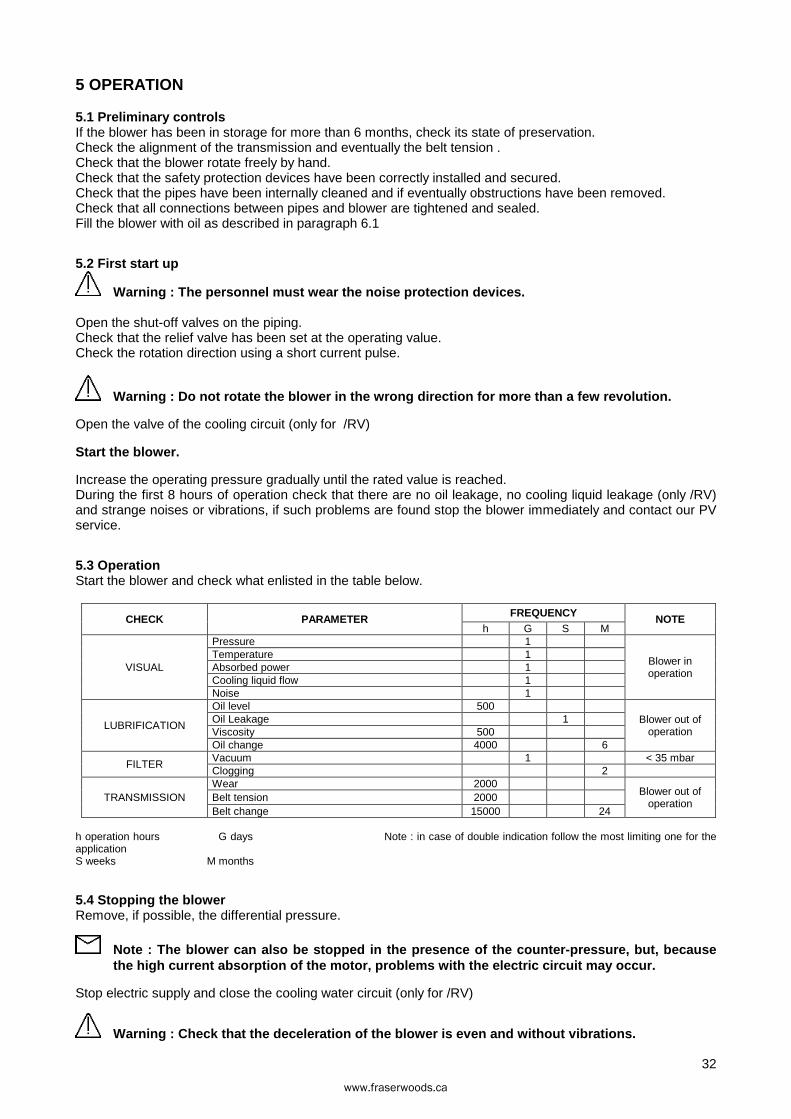
5.3 Operation Start the blower and check what enlisted in the table below.
CHECK PARAMETER FREQUENCY
NOTE h G S M
VISUAL
Pressure 1
Blower in operation
Temperature 1 Absorbed power 1 Cooling liquid flow 1 Noise 1
LUBRIFICATION
Oil level 500 Blower out of
operation Oil Leakage 1 Viscosity 500 Oil change 4000 6
FILTER Vacuum 1 < 35 mbar Clogging 2
TRANSMISSION Wear 2000
Blower out of operation
Belt tension 2000 Belt change 15000 24
h operation hours G days Note : in case of double indication follow the most limiting one for the application S weeks M months
5.4 Stopping the blower Remove, if possible, the differential pressure.
Note : The blower can also be stopped in the presenc e of the counter-pressure, but, because the high current absorption of the motor, problems with the electric circuit may occur.
Stop electric supply and close the cooling water circuit (only for /RV)
Warning : Check that the deceleration of the blower is even and without vibrations.
www.fraserwoods.ca
33
6 MAINTENANCE Stop the blower and auxiliary system as indicated in the paragraph 5.4
Warning : Disconnect the electric supply, lock the g eneral switching open position with the key and conserve it during service operation
Insulate the blower from the plant and restore the atmospheric pressure into it
Warning : The gas contained in the plant may be hot, toxic and irritant
Warning : Wait until the blower returns at ambient temperature (<40°C)
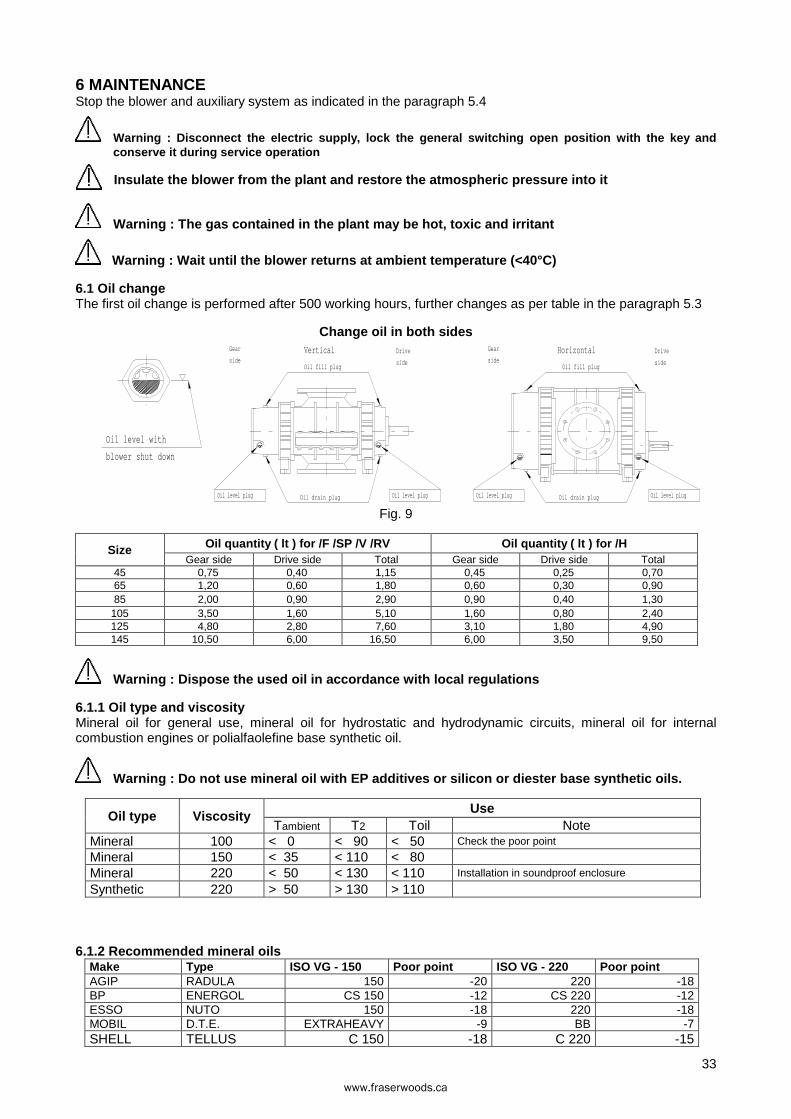
6.1 Oil change The first oil change is performed after 500 working hours, further changes as per table in the paragraph 5.3
Change oil in both sides
Fig. 9
Size Oil quantity ( lt ) for /F /SP /V /RV Oil quantity ( lt ) for /H Gear side Drive side Total Gear side Drive side Total
45 0,75 0,40 1,15 0,45 0,25 0,70 65 1,20 0,60 1,80 0,60 0,30 0,90 85 2,00 0,90 2,90 0,90 0,40 1,30
105 3,50 1,60 5,10 1,60 0,80 2,40 125 4,80 2,80 7,60 3,10 1,80 4,90 145 10,50 6,00 16,50 6,00 3,50 9,50
Warning : Dispose the used oil in accordance with lo cal regulations
6.1.1 Oil type and viscosity Mineral oil for general use, mineral oil for hydrostatic and hydrodynamic circuits, mineral oil for internal combustion engines or polialfaolefine base synthetic oil.
Warning : Do not use mineral oil with EP additives o r silicon or diester base synthetic oils.
Oil type Viscosity Use Tambient T2 Toil Note
Mineral 100 < 0 < 90 < 50 Check the poor point
Mineral 150 < 35 < 110 < 80 Mineral 220 < 50 < 130 < 110 Installation in soundproof enclosure
Synthetic 220 > 50 > 130 > 110
6.1.2 Recommended mineral oils Make Type ISO VG - 150 Poor point ISO VG - 220 Poor point AGIP RADULA 150 -20 220 -18 BP ENERGOL CS 150 -12 CS 220 -12 ESSO NUTO 150 -18 220 -18 MOBIL D.T.E. EXTRAHEAVY -9 BB -7 SHELL TELLUS C 150 -18 C 220 -15
HorizontalGear
sideDrive
sideOil fill plug
Oil drain plug Oil level plugOil level plug
Oil fill plug
Oil drain plug
Oil level with
blower shut down
Vertical Drive
side
Gear
side
Oil level plugOil level plug
www.fraserwoods.ca
34
6.2 Replacing the shaft seal For the identification of parts see the drawings at pages 37 and 38 . Disassemble the drive Empty the lubricating oil out of the sump 12A
Warning : Dispose the used oil in accordance with local regulations
Disassemble the sump 12A Clean the housing of any residues and/or deposits. Replace the seal ring pos. 43 Reassemble the sump 12A Refill the sump 12A with new lubricating oil as per paragraph 6.1.2 Couple the motor as shown in paragraph 4.4.1 o 4.4.2.
6.3 Cleaning of compression chamber Clean the internal surface of the chamber and the surface of the rotors from any deposits and rust by using solvents and a scraper
Warning : Keep to prescribed safety rules when using solvents and wear protection glasses and safety gloves
Note : Do not damage the internal surface of the chamber and the surface of the rotors surface when using the scraper.
6.4 Check of the gear clearance For the identification of parts see the sections at pages 37 and 38. Empty the lubricating oil out of the sump 12B
Warning : Dispose the used oil in accordance with local regulations
Disassemble the gear sump 12B Measure the clearance between the gear teeth according to the attached table 264468 . In order to do this secure one of the gears and rotate the other until there is no contact. Reassemble the sump 12B Refill the sump 12B with new lubricating oil as shown in paragraph 6.1.2 Send the table 264468 filled out with measured clearances to ROBUSCHI. (or any authorized distributor) for their review.
6.5 Check of the rotors clearance Disassemble the inlet piping Insert gauges into the inlet opening to measure the clearance of the rotors in various positions, turning the drive shaft by hand according to the attached table 264468.
Warning : During this operation pay attention to rotors, which can cause the squeezing of the finger and hands.
Reassemble the inlet piping together with the silencer if present Send the table filled out with measured clearance to ROBUSCHI (or any authorized distributor) for their review.
www.fraserwoods.ca
35
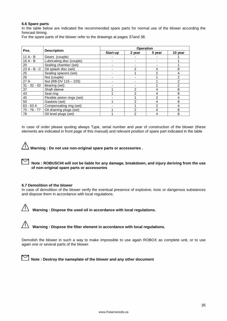
6.6 Spare parts In the table below are indicated the recommended spare parts for normal use of the blower according the forecast timing. For the spare parts of the blower refer to the drawings at pages 37and 38.
Pos. Description Operation
Start-up 2 year 5 year 10 year 11 A - B Gears (couple) - - - 1 16 A - B Lubricating disc (couple) - - - 1 20 Sealing chamber (set) - - - 1 23 A - B - C Oil splash disc (set) - 2 4 8 25 Sealing spacers (set) - 1 2 4 26 Nut (couple) - - 1 2 27 A Nut (RB-DV 115 – 225) - - 1 2 31 - 32 - 33 Bearing (set) - - 1 2 37 Shaft sleeve 1 2 4 8 43 Seal ring 1 2 4 8 45 Flexible piston rings (set) - 1 2 4 50 Gaskets (set) 1 2 4 8 63 - 63 A Compensating ring (set) - 1 2 4 75 - 76 - 77 Oil draining plugs (set) 1 2 4 8 78 Oil level plugs (set) 1 2 4 8
In case of order please quoting always Type, serial number and year of construction of the blower (these elements are indicated in front page of this manual) and relevant position of spare part indicated in the table
Warning : Do not use non-original spare parts or accessories .
Note : ROBUSCHI will not be liable for any damage, breakdown, and injury deriving from the use of non-original spare parts or accessories
6.7 Demolition of the blower In case of demolition of the blower verify the eventual presence of explosive, toxic or dangerous substances and dispose them in accordance with local regulations.
Warning : Dispose the used oil in accordance with local regulations.
Warning : Dispose the filter element in accordance with local regulations.
Demolish the blower in such a way to make impossible to use again ROBOX as complete unit, or to use again one or several parts of the blower.
Note : Destroy the nameplate of the blower and any other document
www.fraserwoods.ca
36
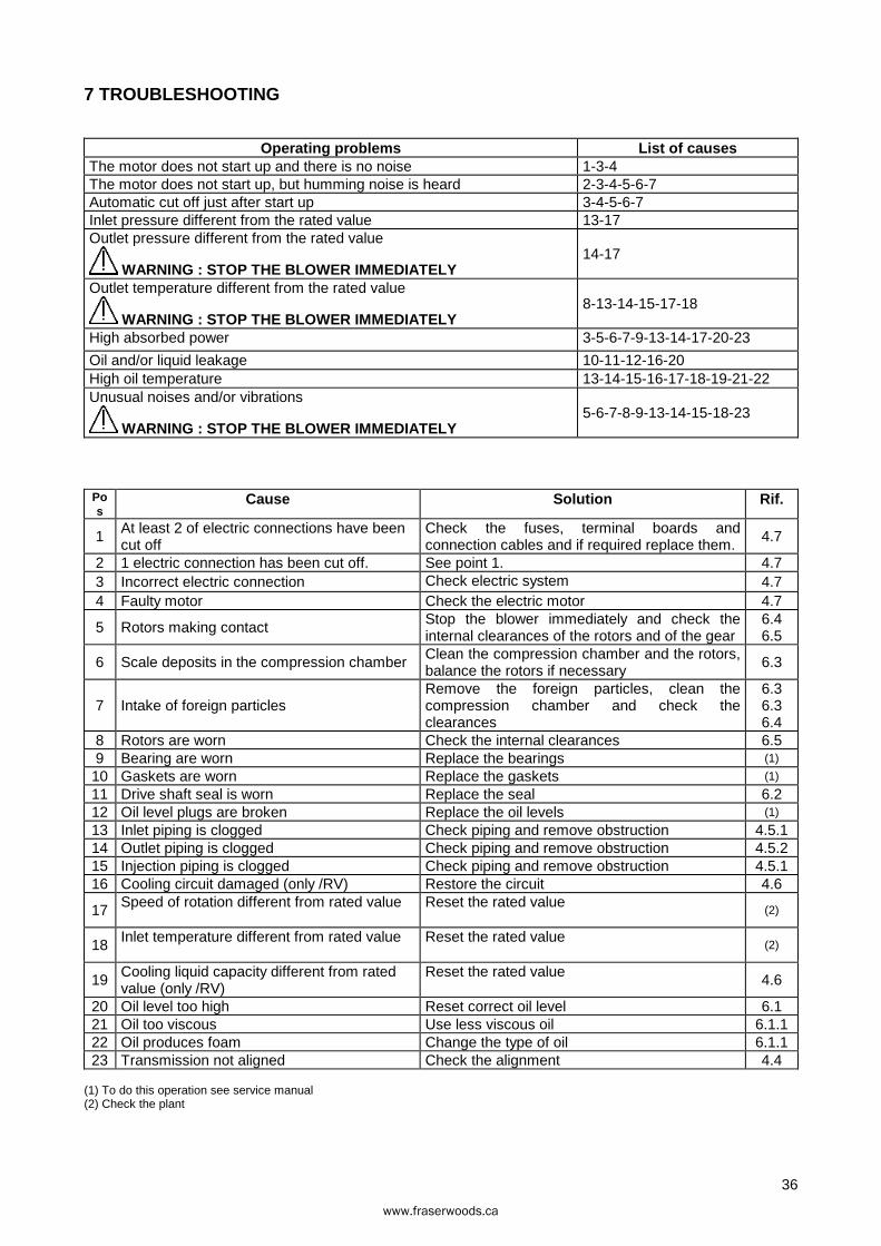
7 TROUBLESHOOTING
Operating problems List of causes The motor does not start up and there is no noise 1-3-4 The motor does not start up, but humming noise is heard 2-3-4-5-6-7 Automatic cut off just after start up 3-4-5-6-7 Inlet pressure different from the rated value 13-17 Outlet pressure different from the rated value
WARNING : STOP THE BLOWER IMMEDIATELY 14-17
Outlet temperature different from the rated value
WARNING : STOP THE BLOWER IMMEDIATELY 8-13-14-15-17-18
High absorbed power 3-5-6-7-9-13-14-17-20-23
Oil and/or liquid leakage 10-11-12-16-20 High oil temperature 13-14-15-16-17-18-19-21-22 Unusual noises and/or vibrations
WARNING : STOP THE BLOWER IMMEDIATELY 5-6-7-8-9-13-14-15-18-23
Pos
Cause Solution Rif.
1 At least 2 of electric connections have been cut off
Check the fuses, terminal boards and connection cables and if required replace them.
4.7
2 1 electric connection has been cut off. See point 1. 4.7 3 Incorrect electric connection Check electric system 4.7 4 Faulty motor Check the electric motor 4.7
5 Rotors making contact Stop the blower immediately and check the internal clearances of the rotors and of the gear
6.4 6.5
6 Scale deposits in the compression chamber Clean the compression chamber and the rotors, balance the rotors if necessary
6.3
7 Intake of foreign particles Remove the foreign particles, clean the compression chamber and check the clearances
6.3 6.3 6.4
8 Rotors are worn Check the internal clearances 6.5 9 Bearing are worn Replace the bearings (1)
10 Gaskets are worn Replace the gaskets (1)
11 Drive shaft seal is worn Replace the seal 6.2 12 Oil level plugs are broken Replace the oil levels (1)
13 Inlet piping is clogged Check piping and remove obstruction 4.5.1 14 Outlet piping is clogged Check piping and remove obstruction 4.5.2 15 Injection piping is clogged Check piping and remove obstruction 4.5.1 16 Cooling circuit damaged (only /RV) Restore the circuit 4.6
17 Speed of rotation different from rated value Reset the rated value (2)
18 Inlet temperature different from rated value Reset the rated value (2)
19 Cooling liquid capacity different from rated value (only /RV)
Reset the rated value 4.6
20 Oil level too high Reset correct oil level 6.1 21 Oil too viscous Use less viscous oil 6.1.1 22 Oil produces foam Change the type of oil 6.1.1 23 Transmission not aligned Check the alignment 4.4
(1) To do this operation see service manual (2) Check the plant
www.fraserwoods.ca
37
8 DISASSEMBLY AND REASSEMBLY
Disassembly the blower within the guarantee period results in the cancellation of the guarantee. Disassembly, repair work and reassembling of the blower must be carried out only by qualified personnel and with the aid of suitable equipment and relevant manual. This manual contains only the instructions for preventative maintenance. For any references to components see the drawings at pages 37 and 38.
Note : Guarantee does not cover damages caused by o perations carried out incorrectly during disassembly and/or reassembling of the blower.
8.1 Disassembly
Warning : Before starting disassembly stop the blow er by following the procedure described at paragraph 6.
Disassemble the drive components (pulleys or coupling) following the manufacturer’s instructions if there are locking devices or by means of an extractor if attached directly onto the shaft.
Warning : Do not hammer the shaft coupling or pulley.
Empty the cooling circuit (only /RV) and disconnect the relevant piping. Drain the lubricating oil from the sumps 12A e 12B
Warning : Dispose the used oil in accordance with l ocal regulations
8.1.2 Disassembly of drive side sump Remove the key 30. Lock the cover 5A to the casing with at least 4 clamps. Loose the fixing screws and extract the sump 12A together with seal ring pos. 43
8.1.3 Disassembly of gear side sump Lock the cover 5B to the casing with at least 4 clamps. Loose the fixing screws and extract the sump 12B .
8.2 Reassembling Before reassembling, thoroughly clean all components and lubricate with oil those components, which have to slide over each other.
8.2.1 Reassembling of drive side sump. Mount the seal ring 43 onto sump 12A using special equipment in order to avoid damaging the lip of the seal. Lubricate the lip of the seal and sliding housing on the shaft with grease. Mount the sump 12A on the cover 5A with a new gasket 50 in between.
Warning : Do not damage the lip of the ring 43.
Secure the sump 12A with the relevant screws
8.2.2 Reassembling of gear side sump Mount the sump 12B onto cover 5B with a new gasket 50 in between. Secure the sump 12B with the relevant screws
PD Blower & Vacuum Pump Service & Repair Facility 120 – 10293 276 ST, Acheson, Alberta, Canada T7X 6A5
T: 780.962.1827 F: 780.962.1830 E: [email protected]
Recommended