This is the post-print version of the final paper published in Computers in Industry, 64(7), 785-797, 2013. The published article is available from http://www.sciencedirect.com/science/article/pii/S016636151300095X. Changes resulting from the publishing process, such as peer review, editing, corrections, structural formatting, and other quality control mechanisms may not be reflected in this document. Changes may have been made to this work since it was submitted for publication. Copyright @ 2013 Elsevier B.V.
Instant 3D Design Concept Generation and Visualisation
by Real-Time Hand Gesture Recognition
Jinsheng Kang, Kang Zhong, Shengfeng Qin, Hongan Wang, David Wright
Abstract:
3D conceptual design is a creative process. While the designers are in the
inspirational mode, they want to quickly express the design ideas in 3D and
visualize it in real time without obstacle. In an exploration of a new,
natural and more user friendly interface to assist rapid 3D conceptual
generation and visualization, a prototype system of hand gesture and
motion capture based user interface has been proposed and
implemented. In this paper, we present the framework and components
of this real time 3D conceptual generation and visualization system.
Hand gestures were designed with the consideration of ease to use and the
suitability for real time continuous recognition. Rule-based intelligent
menu/icons were designed which changes the prompts according to the
design process and expected operations. Real time hand gesture
recognition was realised by skeleton model based template matching,
and the use of Hidden Markov Models (HMMs). The recognised hand
gestures become command script in OpenSCAD environment, and the
3D design concept was instantly generated and displayed on the
screen. A case study was conducted for the initial evaluation of the
system.
Keywords:
3D conceptual design, Hand gesture, Motion capture, Computer Aided Design,
Concept Generation and Visualisation.


1 Introduction
3D design concept generation and visualisation is an important part in conceptual design, in
order to express, validate and evaluate the design ideas in 3D space. With the rapid development of
computer hardware, especially CPU and GPU, 3D modelling in current computer-aided design
(CAD) system becomes more and more powerful. However, the user interaction method of current
CAD software has changed little, and become one of the bottlenecks of rapid 3D conceptual design.
The keyboard and mouse based interface makes current CAD systems difficult to use for rapid 3D
conceptual design generation and exploration. This issue has two aspects. First, conceptual design is
a creative process, and a combination of art and engineering. While designers are in the creative
design mode with inspiration, they want to quickly express the design ideas in 3D without obstacle.
However, operating current CAD software to produce 3D conceptual design is time consuming and
sometimes a burden - especially in the concept stages where designs change frequently. Secondly,
the modelling with 3D CAD software requires complete, concrete and precise design information as
input, which is often not available at the conceptual design stage. Therefore, it is difficult for
designers to create rapidly 3D concept shapes, and change designs in current CAD systems. Zheng
et al [1] discussed the drawbacks of CAD systems in 3D concept design and the need for
improvement on user interface. Robertson and Radcliffe investigated the influences of current CAD
systems on circumscribed thinking, premature design fixation, and bounded ideation [2].
Due to these drawbacks of traditional CAD systems, attempts have been made to allow designers
to model 3D objects using more natural and efficient interaction mechanisms. The 3-Draw system
[3] used a pair of hand-held, 6 DOF input devices to let the designer sketch out ideas in 3D.
Recently, the system developed by Chen et al. [4] allowed users to design 3D objects by sketching in
mid air the wireframes of the objects with an easily-tracked wand. The real time 3D positions of the
strokes of the wand were captured by a camera, and the wireframes and the surfaces being developed
were displayed on the PC screen to guide the user to draw more and more complex objects.
However, users need to have a very good spatial imagination to use these systems, and wireframe
modelling inherited the difficulties in surface editing and generating complex shapes. In a recently
developed “Shape-It-Up” system, creative expression of 3D shapes in conceptual design was realised
through the naturalistic integration of hand gestures, using a modelling scheme of intelligent
generalized cylinders [5].

Attempts have also been made to integrate virtual reality with CAD, and develop some VR-based
CAD systems. This type of system allows designers to create and modify CAD models using 3D
devices in the virtual environment. DesignSpace [6], as an experimental testbed developed by
Stanford University, aimed to offer the designer better access to the product models. From
DesignSpace, several projects were developed, such as TalkingGlove, CutPlane, VirtualHand,
VirtualGrasp, and TeleSign, which allow conceptual designers to create simple surface and solid
geometric shapes using voice and gestures in mechanical design. COVIRDS (Conceptual Virtual
Design System) [7, 8] provided a 3D virtual environment for the designer to model mechanical and
electro-mechanical components. The system uses voice commands and hand motion/action as input
modes for the designer to create 3D designs. Virtual hands have been modelled and integrated into
virtual production line in an attempt to design better human-machine interactions [9]. Zheng et al [1]
developed a desktop CAD system, which used a CyberGlove as an input device, for facilitating
conceptual design. In this system, designers are allowed to use some simple gestures to conduct
various geometric shape operations instead of depending solely on keyboard and mouse. Fuge et al
[10] developed a system for directly creating and modifying free form surfaces through 3D hand
gestures wearing a glove with coloured fingertips, in an augmented reality environment. “Mockup
Builder” is a newly developed semi-immersive environment for users using 3D hand gestures to
sketch, create and manipulate 3D shapes in conceptual design [11]. In these VR/AR based systems,
the hand gestures defined were too simple to accomplish the whole design process alone. In other
words, these systems did not focus mainly on hand gestures as interaction methods.
Hand gesture based interaction in 3D space is considered as an intuitive way of interacting with
3D objects [12, 13]. For example, the GIVEN [14] toolkit (Gesture based Interactions in Virtual
Environments) focused on collision detection between the user's hand and the object being
manipulated and defined a gestural language based on this interaction. Hand gestures have been used
to describe 3D objects [15] and to control 3D character animation [16]. PolyShop [17] environment
allowed the use of both hands for various tasks in a VE. With the development of hand gesture
recognition in recent years, researchers [18, 19, 20] have paid attention to generating 3D models
based on hand gesture and motion. An early effort by Shih and Shih [21] used gesture modelling to
simulate architectural space and objects. Hand gestures designed by sign language grammar such as
nouns or verbs are used to model 3D buildings. However, these gestures are too complicated for

designers to remember and to use at the early conceptual design stages, and it is difficult to recognize
them in real time. An alternative technique was to move a stylus held by one hand to perform 3D
design, as in our previous work using hand motions to create large-sized free-from surface models
[22], physical models [23] and architectural models [24].
In view of previous research, although various efforts have been made, the improvement of the
user interface for rapid 3D conceptual design still remains as a great challenge. Recently, hand
gesture as a natural way to interact with computers and to control domestic appliances has gained
great attention both from academia and industry, and is considered as a new trend for the future. In
the meantime, the use of motion capture system is increasingly popular, given the fact that more and
more easy-to-use motion capture systems at affordable price are available, such as Kinect. Based on
this background and our previous research on using hand motions for design, the objective of the
current research is to investigate the feasibility of a hand gesture and motion capture-based user
interface to allow designers to interactively realise rapid 3D concept design in real time. Although
motion capture system has the capability for real time computer animation, this is the pioneer
research on using motion capture system for design application in real time. The robustness of
algorithms used in the system in real time hand gesture recognition, real time data transfer and
transform, as well as real time 3D object generation and display, are also to be examined.
2 System and methods
2.1 System framework
The framework of the whole system is shown in Fig. 1, which consists of three parts: a
commercial motion capture system, a real time hand gesture recognition engine, and a customized
3D design environment. In this 3D conceptual design system, the designer can perform a series of
hand gestures to create, manipulate, and merge 3D solids. The designer’s hand motion is captured by
a motion-capturing system, and then sent to the hand gesture recognition engine as input. The
recognition engine processes and classifies the input motion data in real time. The results of
recognition are converted into a series of detailed commands for 3D conceptual design, and the
outcome of each command is displayed in the 3D design environment in WYSIWYG style.

2.2 Hand motion capture
A three-dimensional optical motion capture system from Motion AnalysisTM
is used to capture
the designer’s hand motion. Seven Eagle digital cameras are located circularly to acquire hand
motion date in a rough volume of 2m × 3m × 1.5m, as shown in Fig. 2. The locations of the cameras
and the size of the capture volume can be adjusted depending on the requirement. For hand motion
capture, small reflective markers (5mm in diameter) are attached to the designer’s hands, so the
cameras are located close to the user in order to capture the markers easier and more accurately.
According to the discussion in the previous section on hand skeleton model, reflective markers are
placed at the closest positions to corresponding hand joints, but not exactly on the joints in order to
reduce the unnecessary movement of the makers, as shown in Fig. 3a. A skeleton-based hand
template is created within the motion capture software (Fig. 3b).
2.3 The design of hand gesture set
The criteria for our hand gesture set design are that, first the hand gesture set should be natural
and easy to use for designers, requiring no special training. Secondly, the hand gesture set should be
suitable for continuous recognition in real time. With reference to American Sign Language (ASL)
and some previous work [15, 1, 18], we studied the minimum set of commands that are necessary for
3D conceptual design based on CSG, and proposed the hand gesture set. Recognition of hand
gestures involves 1) static hand gesture: static finger configuration without hand movement and 2)
dynamic hand gesture: dynamic hand movement with or without finger motion. In comparison with
static hand gesture (posture), dynamic hand gesture recognition is more difficult, especially in real
time. This is mainly due to the difficulties in determining the start and end points of a meaningful
gesture pattern from a continuous stream of input signals. In order to solve this problem, each hand
gesture specified for 3D design in our system includes two parts: the posture of the left hand and the
dynamic gesture of the right hand. The left hand indicates the type of operation that the designer
wants to take, and the right hand specifies the exact action. The user keeps his/her left hand posture
unchanged during one operation, i.e., the start and end of the designer’s left hand posture indicates
the corresponding start and end time of a dynamic action gesture on the right hand. Through this
mechanism, the hand gesture recognition system can easily segment the meaningful gestures from
the continuous input signals which are 3D coordinates of markers on both hands in our motion
capture system.
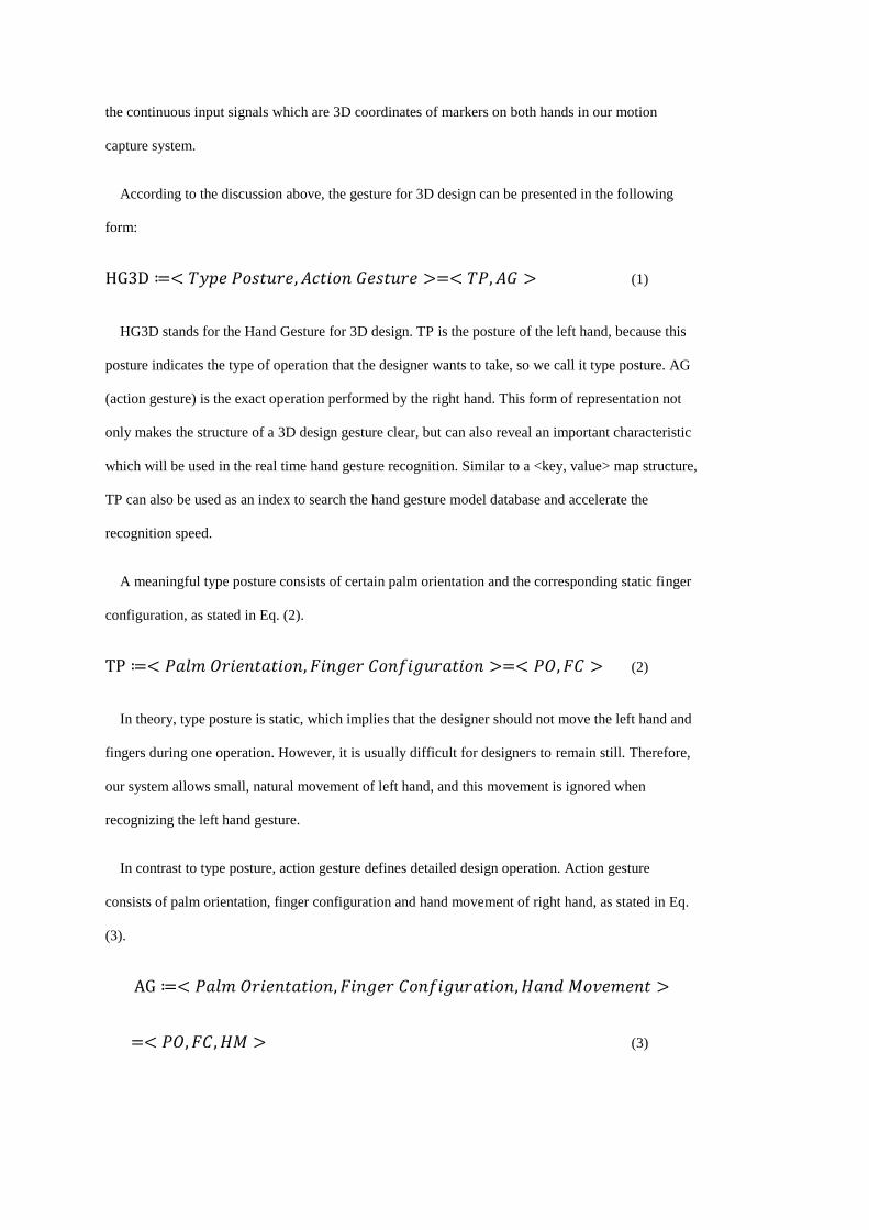
According to the discussion above, the gesture for 3D design can be presented in the following
form:
(1)
HG3D stands for the Hand Gesture for 3D design. TP is the posture of the left hand, because this
posture indicates the type of operation that the designer wants to take, so we call it type posture. AG
(action gesture) is the exact operation performed by the right hand. This form of representation not
only makes the structure of a 3D design gesture clear, but can also reveal an important characteristic
which will be used in the real time hand gesture recognition. Similar to a <key, value> map structure,
TP can also be used as an index to search the hand gesture model database and accelerate the
recognition speed.
A meaningful type posture consists of certain palm orientation and the corresponding static finger
configuration, as stated in Eq. (2).
(2)
In theory, type posture is static, which implies that the designer should not move the left hand and
fingers during one operation. However, it is usually difficult for designers to remain still. Therefore,
our system allows small, natural movement of left hand, and this movement is ignored when
recognizing the left hand gesture.
In contrast to type posture, action gesture defines detailed design operation. Action gesture
consists of palm orientation, finger configuration and hand movement of right hand, as stated in Eq.
(3).
(3)

There are two categories of action gestures. In category one action gestures, the trajectory of right
hand (precisely, the index finger tip) will form the designed geometry. This category of action
gesture is used for creating 2D primitives, which are the basis for 3D solid generation. The type
posture for this operation is to open the left hand and keep all fingers together with the hand palm
facing the screen, as shown in Fig. 4a. The left hand represents a 2D plane, and the designer can
draw a 2D shape using his/her right index finger (Fig. 4b) while keeping this type posture. The
system will know that the designer is drawing a 2D geometric figure and recognize it according to its
trajectory.
There are several primitive geometric figures that the designer can draw using his/her right index
finger in the system: square, triangle, circle, trapezoid, etc. Then by extruding a 2D shape along a
path, i. e., along the X axis in Fig. 4c, the designer can create some basic solids, such as box,
cylinder, wedge, and so on. For the 3D shape which has a geometric central axis, such as sphere,
cone or torus, revolving certain 2D geometry around a central axis (Fig. 4d) is the better way to
create it. We did not use hand gestures to directly create certain 3D solids, because that requires the
designer to remember too many design gestures (one gesture for each 3D primitive solid).
All other action gestures belong to the second category. Some of these action gestures have no
hand movement at all, such as action gestures for Union, Subtract, Intersect, Select, Redo, Undo,
Copy and Past. Some of these action gestures have one simple hand movement perpendicular to the
hand palm, to represent the direction of operation, such as Extrude, Zoom in/out, Scale, Translate
and Rotate. The main concern for designing these action gestures is for them to be easily
recognisable in real time. The complete set of all the hand gestures in our system, including type
postures (TP) of the left hand and the action gestures (AG) of right hand, are shown in Fig. 4, Table
1 and Table 2.
All the hand gesture commands provided by the system are summarised in Fig. 5 according to
their functionalities. These hand gesture commands can be classified into two main categories: 3D
object operations and workspace operations. 3D object operations involve common functions for 3D
design, such as creating, manipulating, and merging solids, while workspace operations just involve
six frequently-used operations: undo, redo, copy, paste, zoom in and zoom out. The design of the

hand gesture set is also aimed at making the system as simple and tidy as possible, in order to
facilitate real time hand gesture recognition.
2.4 Skeleton-based hand model
Choosing a proper hand model is the basis for efficient hand gesture recognition, because the
hand model determines not only the features required for the recognition algorithm, but also the set-
up of hand motion capture. A skeleton-based model of the human hand [19, 20] is used in our
system, as shown in Figure 6. In this type of hand models, two sets of parameters are frequently used
for the gesture recognition – angular (joint angles) and linear (phalange lengths and palm
dimensions). In our system, the former type of parameters is used as the main features to determine
the finger configuration, mainly because the latter one is varying for different people, and in
contrast, joint angles vary little between different users for the same gesture. Besides joint angles,
the distances between neighbouring fingertips are also evaluated in order to distinguish the
predefined gestures from those unmeaning ones, and to enhance the recognition capability of our
system.
As the part of a skeleton-based model, some relationships between the movements in
neighbouring finger joints are used to reduce the number of hand gesture parameters needed to
collect. Rijpkema and Girard [21] proposed a widely used constraint, as stated by Eq. (4).
(4)
Where and represent the flexion DOF for the PIP (Proximal Interphalageal) and DIP
(Distal Interphalangeal) joints of each finger. This is a strong constraint and is adopted by many
researchers working on hand gesture analysis. According to this constraint, the angle of the DIP joint
of each finger does not need to be captured if the angle of the corresponding PIP joint is available.
3 Calculation
During a design process, the positions of hand markers are captured and recorded via the
software EVaRT 5.0. Based on the event-driven-architecture (EDA) and the functionalities provided
by EVaRT 5.0 SDK, the motion data is captured and processed in real time. The captured motion
data is immediately processed through a second order Butterworth low-pass filter with a cut-off

frequency of 5Hz before the feature extraction to eliminate the noise. Real time hand gesture
recognition is the key for the successful implementation of the rapid 3D conceptual design system.
Basically, two mechanisms for real time recognition are employed in the system, template matching
and hidden Markov model (HMM) [22]. These will be discussed in detail in the following sections.
3.1 Hand posture recognition
As the discussion in section 2.3 indicates, the posture is composed of certain palm orientation
and the corresponding static finger configuration. The latter is determined by joint angles and
distances between neighbouring fingertips which can be evaluated directly from the coordinates of
markers. However, the approach to recognize the palm orientation is not so straightforward. In our
system three markers, one of which is located at the wrist joint and the other two are located at the
MCP (Metacarpophalangeal) joints of the index and little fingers respectively, are used to define the
palm orientation, as shown in Fig. 7a.
In a three-dimensional Euclidean space, any three points will form a plane, provided that they are
not collinear. The coordinates of three markers, , and should be sufficient to define the palm
plane. However, the mathematical definition of a plane through three points is determined by the
coordinate values of three points, and planes with the same orientation but different location will
result in different mathematical expressions, and thus it is unsuitable to be directly used for real time
hand gesture recognition. This is because in hand gesture recognition we are only interested in the
palm plane orientation, and the palm plane location is of no interest to us, and can not be stored in
the database. Secondly, the palm plane orientation needs to be converted form continuous values to
discrete data in order to meet the requirement of real time template matching. Therefore, we
developed a new method to evaluate the palm orientation in real time, which includes three steps:
(1) Obtain two vectors from the given three points: and
(Fig. 7 (a)).
(2) Project the vector onto the xy-plane, then find the angle between this projection and x-
axis, and denoted it as . is measured from the positive direction of x-axis to the positive
direction of projected vector, and lies within the range . If the vector is
perpendicular to the xy-plane, the vector will be used to project onto xy-plane, and the
angle between its projection and x-axis will be denoted as . Similarly, the vector is
projected onto and zx-plane as well, and the angle between the projection and z-axis is denoted
as θzx, whilst the vector is projected onto yz-plane and the angle between the projection
and y-axis is denoted as .
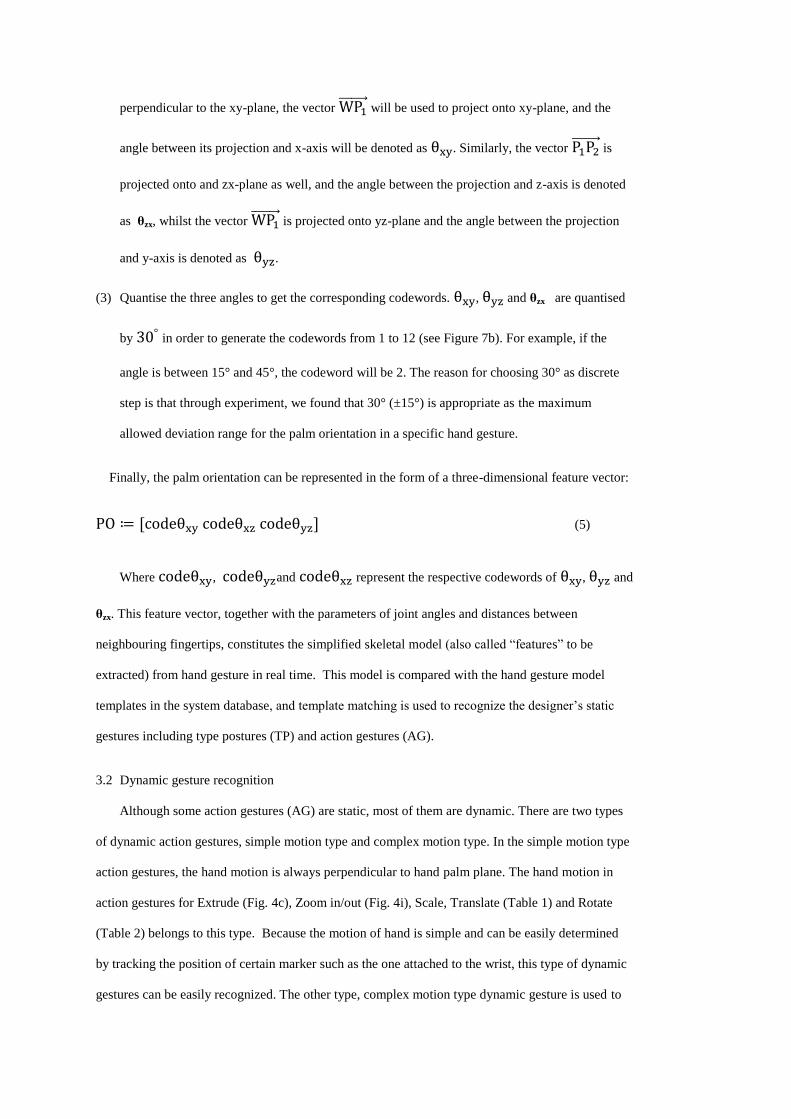
(3) Quantise the three angles to get the corresponding codewords. , and θzx are quantised
by in order to generate the codewords from 1 to 12 (see Figure 7b). For example, if the
angle is between 15° and 45°, the codeword will be 2. The reason for choosing 30° as discrete
step is that through experiment, we found that 30° (±15°) is appropriate as the maximum
allowed deviation range for the palm orientation in a specific hand gesture.
Finally, the palm orientation can be represented in the form of a three-dimensional feature vector:
(5)
Where , and represent the respective codewords of , and
θzx. This feature vector, together with the parameters of joint angles and distances between
neighbouring fingertips, constitutes the simplified skeletal model (also called “features” to be
extracted) from hand gesture in real time. This model is compared with the hand gesture model
templates in the system database, and template matching is used to recognize the designer’s static
gestures including type postures (TP) and action gestures (AG).
3.2 Dynamic gesture recognition
Although some action gestures (AG) are static, most of them are dynamic. There are two types
of dynamic action gestures, simple motion type and complex motion type. In the simple motion type
action gestures, the hand motion is always perpendicular to hand palm plane. The hand motion in
action gestures for Extrude (Fig. 4c), Zoom in/out (Fig. 4i), Scale, Translate (Table 1) and Rotate
(Table 2) belongs to this type. Because the motion of hand is simple and can be easily determined
by tracking the position of certain marker such as the one attached to the wrist, this type of dynamic
gestures can be easily recognized. The other type, complex motion type dynamic gesture is used to

create 2D primitives (Fig. 4b), and requires tracking the trajectory of the fingertip and recognizing
which 2D geometric shape the designer is drawing. In order to accomplish this task, a real time
recognition algorithm based on HMM is employed.
The trajectory of the fingertip can be represented as a 3D polyline in time sequence: { }
, where is a 3D position of the fingertip marker, and the direction of movement is
determined by two consecutive points from the movement path (Fig 8). Since we setup the motion
capture space with the plane in front of the designer as xy-plane, the fingertip motion in creating 2D
primitive action gesture is expected to be in xy-plane. In order to accelerate the recognition process,
a 3D to 2D reduction is carried out. Given any two consecutive points and , the direction of
finger movement is determined as follows:
(1) Compute , , and find
(| | | | | |).
(2) Calculate ( ) ( ) and find out which one is
closest to zero, then assign it to zero (implies that its dimension is zero). The other two
components will constitute a plane to replace the 3D space. For example, if dz is zero, xy-plane
will replace the 3D space.
(3) Project the vector onto that plane and calculate the angle between the horizontal axis
and this projection. Taking as an example, the angle is given by (
).
(4) Quantize the angle at an interval of in order to generate the codewords from 1 to 18 (similar
to Fig. 7b).
A codeword of the direction can be obtained for each frame sampled for gesture recognition
(except the first frame) from the motion data. For a hand gesture sampled for fames, a ( )
dimensional feature vector is obtained and used as input to HMM.
In the system database there are discrete HMMs corresponding to each 2D primitives. According
to the experimental results of some previous researchers [23, 24], Left-Right Banded (LRB) model

structure (Figure 9) performed better than other HMM topologies for dynamic hand gesture
recognition in respect to the recognition rate and computation consumption. Therefore, LRB HMMs
with different number of states are used to model the finger motion in the system. Basically, there is
no fixed value for the number of states for all HMMs, and the number of states is determined
individually based on the complexity of each dynamic hand gesture trajectory to generate 2D
primitive. The number of states for each HMM is determined by experiment, and the criteria is to
have the minimum number of states to robustly distinguish a trajectory. This is because the excessive
number of states can generate the over-fitting problem and more training samples are needed. If the
number of states is insufficient, the discrimination power of the HMM will be reduced since at least
one state should be modelled for every geometric features in the 2D primitive trajectory.
All these initial HMMs are trained by utilizing the Baum-Welch algorithm [25]. In order to
guarantee that a full training is completed, sufficient training samples (more than 20 for each gesture
in our system) are captured and provided. Afterwards, all trained HMMs are organized into an HMM
network (Fig. 10).
The real-time dynamic hand gesture recognition is implemented by using the Forward-Backward
algorithm which evaluates the probability ( | ) that the observation sequence was generated
by the given model . Each feature vector of finger movement, as an observation sequence, is
extracted in real time, and used as the input to the HMM network (Fig. 10). ( | ) is then
calculated in parallel for all gesture HMMs in the network by employing the Forward-Backward
algorithm [24]. If the ( | ) value for model is the maximum, then the sequence will be
classified into class . Because in this algorithm, a model with the maximum ( | ) will be picked
no matter what the input is, there is a possibility that the input gesture is unmeaningful or unrelated
to the current design scenario. In order to correct this problem, a method to provide an adaptive
threshold for classification of meaningful gestures and unrelated finger movements using HMM, as
what Lee and Kim [26] proposed, is also utilized in the system. A hand gesture will be recognised
only if it is with the maximum ( | ) and above the threshold of a HMM. Otherwise, it will be
classified as an unrecognised gesture.
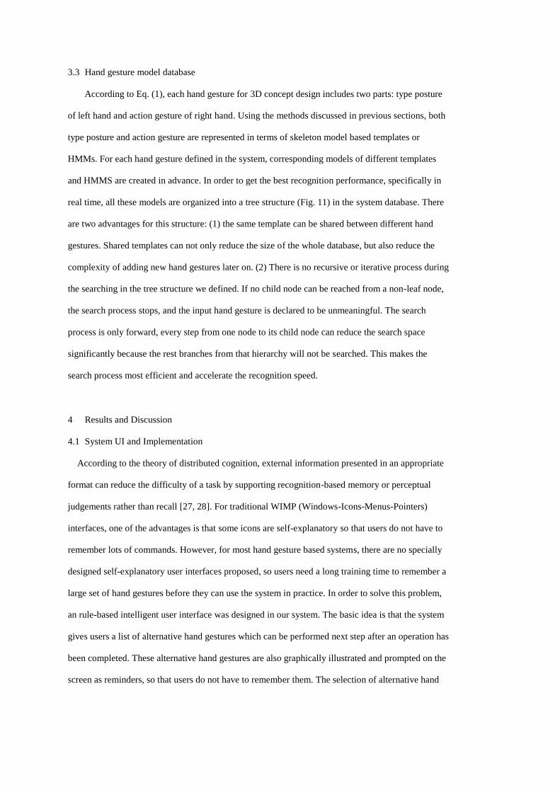
3.3 Hand gesture model database
According to Eq. (1), each hand gesture for 3D concept design includes two parts: type posture
of left hand and action gesture of right hand. Using the methods discussed in previous sections, both
type posture and action gesture are represented in terms of skeleton model based templates or
HMMs. For each hand gesture defined in the system, corresponding models of different templates
and HMMS are created in advance. In order to get the best recognition performance, specifically in
real time, all these models are organized into a tree structure (Fig. 11) in the system database. There
are two advantages for this structure: (1) the same template can be shared between different hand
gestures. Shared templates can not only reduce the size of the whole database, but also reduce the
complexity of adding new hand gestures later on. (2) There is no recursive or iterative process during
the searching in the tree structure we defined. If no child node can be reached from a non-leaf node,
the search process stops, and the input hand gesture is declared to be unmeaningful. The search
process is only forward, every step from one node to its child node can reduce the search space
significantly because the rest branches from that hierarchy will not be searched. This makes the
search process most efficient and accelerate the recognition speed.
4 Results and Discussion
4.1 System UI and Implementation
According to the theory of distributed cognition, external information presented in an appropriate
format can reduce the difficulty of a task by supporting recognition-based memory or perceptual
judgements rather than recall [27, 28]. For traditional WIMP (Windows-Icons-Menus-Pointers)
interfaces, one of the advantages is that some icons are self-explanatory so that users do not have to
remember lots of commands. However, for most hand gesture based systems, there are no specially
designed self-explanatory user interfaces proposed, so users need a long training time to remember a
large set of hand gestures before they can use the system in practice. In order to solve this problem,
an rule-based intelligent user interface was designed in our system. The basic idea is that the system
gives users a list of alternative hand gestures which can be performed next step after an operation has
been completed. These alternative hand gestures are also graphically illustrated and prompted on the
screen as reminders, so that users do not have to remember them. The selection of alternative hand
gestures is based on a set of rules taking into consideration the different design tasks users are
currently performing, as well as the current state of the workspace.
Rule 1: if there is only one 3D object in the workspace, the gestures to be performed on two
objects, such as Boolean operations, are not listed as alternatives.
Rule 2: if there are two 3D solids in the workspace, and no one has been selected, all
manipulation gestures except the ‘Select’ operation are not listed as alternatives; in
contrary, if one 3D solid has been selected, all manipulation gestures except the ‘select’
operation are listed as alternatives.
Rule 3: when the designers perform a type posture, all action gestures working in pair with
this type posture, are listed as alternatives. If some of them are against the Rule 1, they will
be eliminated.
Rule 4: according to the associative relationships among different hand gestures, which are
summarized form common design experience, some gesture commands are frequently
followed by a certain set of other gestures. Drawing a 2D primitive, for example, is most
likely followed by extruding or revolving it to create a 3D shape. The likelihood of next
operation is used to sort the alternatives, with the most likely on the top of the alternative
list.
Rule 5: Workspace operations, including undo, redo, copy and paste, are always as part of
the alternative list.
An example of the prototype system UI is shown in Figure 12. On the left side window, it is the
open source OpenSCAD [29], which is employed as the workspace to display the designed 3D
objects. We did not make any alterations to the OpenSCAD environment, and only use it as the
displaying window. In the current example, it is activated and the designed chair seat panel is
selected (in red). On the right side widow, it is the user interface we implemented. On the top of the
window, the hand gesture recognition result is displayed, and in current example, it is ‘Translate’
along ‘x axis’. In the middle of the window, all the alternatives are listed. In the bottom of the
window, the connection status with motion capture system is displayed.
The prototype system is implemented with Visual C++ and MATLAB. The core recognition
algorithms were written in MATLAB, then compiled to C++ DLL. All other parts in the system,

were programmed with Visual C++. The recognised hand gestures are translated into OpenSCAD
script language, and then displayed in OpenSCAD window. The 3D geometry generation in our
system is accomplished in OpenSCAD, which supports constructive solid geometry. Fig. 13 shows
the system implementation.
4.2 A case study: designing a chair
We tested our hand gesture based rapid 3D conceptual design method with the task of designing a
chair. A small number of undergraduate students, research students performed as designers to carry
out the design task. An example of the design process is as following:
(1) Draw a circle and extrude it to create a cylinder, then repeat to create another cylinder with
different radius and height, then perform the subtract operation to obtain a toroid, as show in
Fig. 14a.
(2) Draw a square and extrude it to create a cube, and then make it intersect with the toroid, as
shown in Fig. 14b. After performing the intersect operation, the back of the chair is obtained
(Fig. 14c).
(3) Draw a square and extrude it to create a cube, scale it (Fig. 14d), which is used as the chair seat
panel.
(4) Union the back of the chair and the chair seat panel together, as shown in Fig.14e.
(5) Draw a circle and extrude it to create a cylinder, and scale it to appropriate size for a chair leg
(Fig. 14f).
(6) Copy this chair leg, for later to duplicate
(7) Move this chair leg to the proper position and perform the union operation.
(8) Paste to generate a duplicated chair leg and move it to the proper position and perform the union
operation.
(9) Repeat Step (8 ) for 2 times to create and position other chair legs. The final chair model is
shown in Fig. 14g.
In our test, the cameras were set to 120 frames per second. The designers spent less than 10 min to
complete the design modelling task after a brief introduction to the system. More chairs created by
designers in this experiment are shown in Fig. 15. However, creating the 3D model from scratch
every time is sometimes unnecessary and time-consuming. To facilitate the usage of our hand

gesture based conceptual design system, some non primitive solids, which are generated from
primitive solids by using Boolean operations, are provided as a library and can be browsed and
picked up and used directly by designers (Fig. 16). Through selecting, manipulating and merging
these solids provided by the library, designers can create many conceptual models rapidly just like
playing Lego.
4.3 Discussion
The 3D shape modelling method in our proposed system is a hand gesture-based procedural
method, and the instantly generated product model is represented by OpenSCAD command scripts in
the form of a sequence of commands used to create the product shape and topology, which is very
similar to the neutral macro file proposed by Cheon et al [30]. The advantage of the procedural
method is that it can capture the design intent, model construction history, features and constraints
[31], which are very important aspects in conceptual design stage. That is why Cheon et al [30]
identified the need to transfer the boundary representation (B-rep) data obtained from 2D sketch into
procedural model. From this point of view, our proposed system is suitable for concept design.
For the purpose of 3D styling in conceptual design, 3D sketch with a digitized pen is another
optional method. We have used the 3D sketch tool ‘Leonar3Do’ to support structural design at the
conceptual design stage [32], and found that a 3D digitalized pen can either provide raw and pure
geometric data for a reversing engineering process to generate a smoothed 3D model or provide a set
of gesture information. In the latter case, it is similar to the proposed system in the current paper, but
the designer will typically operate in one-hand. With the proposed system in the current paper, the
designer will be free from device-induced constraints and use gestures from two hands along with
some body movements to express their 3D design intentions. The accuracy of position information
from the motion capture system is better but the equipment is expensive. The modelling speed is
depending on the reliability of gesture recognition for both systems. In terms of easiness, the system
uses two-hands is generally considered to be easier by the user.
We defined a hand gesture set which contains both left hand gesture and right hand gesture, and
they are collectively called HG3D. The left hand gesture is static without hand and finger
movement, and it is called TP (type posture). TP is used to indicate the category of a specific hand
gesture, i. e., which group (Fig. 11) this hand gesture is belong to. The right hand gesture is dynamic

with hand and finger movement, and it is called AG (action gesture). HG3D contains TP and AG
(Equation 1). For example, Fig 4a is a TP which means now creating 2D primitives, whilst Fig 4b is
an AG which can generate various 2D primitives based on the sketch (trajectory) of index finger. In
the 16 examples in Fig 4, if the illustrated hand gesture is on one hand, it is designated as TP (left
hand) or AG (right hand). If the illustrated hand gesture is on both hands, it is designated as HG3D.
By defining a hand gesture set with TP and AG, hand gesture recognition error has been minimised,
because TP defined the hand gesture category, and within this category, there are only a few different
hand gestures.
The system is currently still in the prototype and development stage, and we are trying to use
different algorithms to optimise the system. Different ready-made MATLAB algorithms can be
easily hooked up with C++ to try out. Once the optimisation process is completed, the entire system
will be implemented with C++ only.
5 Conclusion and future work
A new method of using hand gesture and motion capture system as user interface for rapid 3D
conceptual design in real time has been systematically investigated and tested, and a prototype
system has been implemented. The hand gesture set proposed is simple, natural and kept to minimum
number, and no need for training and tedious remembering. Each hand gesture consists of two parts:
type posture of left hand and action gesture of right hand. The type posture not only indicates the
type of operation, but also used to segment the starting and ending time for the action gesture of right
hand from the continuous input signals. Some simplification and quantisation techniques are
employed in the real time gesture recognition algorithms, such as codewords to represent the palm
orientation and finger trajectory, wrist marker to represent hand movement, PIP angle and fingertip
marker distance as features for hand posture. Experiment results shows that these algorithms are
robust and meet the requirement for real time recognition. The rule-based intelligent user interface
changes the icons instantly according to design process and expected operations, and prompt the
alternative had gestures graphically. The recognised hand gestures are translated into OpenSCAD
script language, and instantly displayed in WYSIWYG style.
The significance of the current research is that it realised using hand gestures only to complete
the entire 3D conceptual design in real time for the first time. Although the prototype system is very
simple, and there are lots of rooms for extension and further improvement, it has revealed the
potential of using hand gestures as a new user interface for rapid 3D conceptual design. Currently,
there is a new trend of using hand gestures to interact with computers and to control domestic
appliances. The principles and techniques reported here can be used for other applications as well,
and they are not restricted to motion capture system and can be adopted in video image based system
as well.
For future work, we will seek alternative algorithms for the recognition of hand gesture
trajectory which require less training than HMMs. We will also extend the system to be able to
handle multiple 3D components and assemble them, and incorporate the standard part library, in
order to design complicated products.
References
[1] Zheng, J. M., Chan, K. W., and Gibson, I. 2001. Desktop virtual reality interface for computer
aided conceptual design using geometric techniques. J. Engineering Design, 12(4), 309-329.
[2] Robertson B, Radcliffe D. 2009. Impact of cad tools on creative problem solving in engineering
design. Computer-Aided Design, 41(3):136–46.
[3] Sachs, E., Roberts, A., and Stoops, D. 1991. 3-Draw: A tool for designing 3D shapes. IEEE
Computer Graphics and Applications, 11(6), 18-26.
[4] Chen, Y., Liu, J., and Tang, X. 2008. Sketching in the Air: A Vision-Based System for 3D Object
Design. IEEE Conference on Computer Vision and Pattern Recognition (CVPR), pp. 1-6.
[5] Vinayak, Murugappan, S., Liu, H., Ramani, K., 2013. Shape-It-Up: Hand gesture based creative
expression of 3D shapes using intelligent generalized cylinders. Computer-Aided Design,
45(2), 277–287.
[6] Chapin, W. L., Lacey, T. A., and Leifer, L. 1994. DesignSpace: A Manual Interaction
Environment for Computer Aided Design, Proceedings of the SIGCHI Conference on
Human Factors in Computing Systems, Boston, Massachusetts, United States, pp. 33-34.
[7] Chu, C-C. P., Dani, T. H., and Gadh, R. 1997. Multi-sensory user interface for a virtual reality
based computer aided design system. Computer Aided Design, 29(10), 709-725.
[8] Chu, C-C. P., Dani, T. H., and Gadh, R. 1998. Evaluation of virtual reality interface for product
shape designs. IIE Transactions, 30(7), 629-643.
[9] Pouliquen, M., Bernard, A., Marsot, J., Chodorge, L., 2007. Virtual hands and virtual reality
multimodal platform to design safer industrial systems. Computers in Industry,58(1), 46-56
[10] Fuge, M., Yumer, M.E., Orbay,G., Kara, L.B., 2012. Conceptual design and modification of
freeform surfaces using dual shape representations in augmented reality environments.
Computer-Aided Design 44 (10), 1020–1032.
[11] De Arau´jo, B.R., Casiez, G., Jorge, J.A., Hachet,M., 2012. Mockup builder: 3D modeling on
and above the surface, Computers & Graphics, http://dx.doi.org/10.1016/j.cag.2012.12.005

[12] O'Hagan, R. G., Zelinsky, A., and Rougeaux, S. 2002. Visual gesture interface for virtual
environments. Interacting with Computers, 14(3), 231-250.
[13] Erol, A., Bebis, G., Nicolescu, M., Boyle, R. D., and Twombly, X. 2007. Vision-based hand
pose estimation: A review. Computer Vision and Image Understanding, 108(1-2), 52-73.
[14] Figueiredo, M., Bohm, K., and Teixeira, J. 1993. Advanced interaction techniques in virtual
environments. Computers and Graphics, 17(6), 655-661.
[15] Holz C, Wilson A., 2011. Data miming: inferring spatial object descriptions from human
gesture. In: Proceedings of the 2011 annual conference on Human factors in computing
systems. New York (NY, USA): ACM; 811–820.
[16] Condell, J., Moore, G., 2009. HandPuppet3D: Motion capture and analysis for character
animation. Artificial Intelligence Review. 31(1-4),45–59.
[17] Mapes, D. P., and Moshell, J. M. 1995. A two-handed interface for object manipulation in a
virtual environment. Presence: Teleoperators and Virtual Environments, 4(4), 403-416.
[18] Wu, Y., and Huang, T. S. 1999. Vision-Based Gesture Recognition: A Review. Lecture Notes in
Computer Science, Vol. 1739, 103-115.
[19] Mitra, S., and Acharya, T. 2007. Gesture Recognition: A Survey. IEEE Trans. Systems, Man,
and Cybernetics, Part C: Applications and Reviews, 37(3), 311-324.
[20] Wang, R. Y. and Popovic, J. 2009. Real-Time Hand-Tracking with a Color Glove, ACM
Transaction on Graphics (SIGGRAPH 2009), 28(3), August 2009.
[21] Shih, N-J. and Shih, W-D. 1996. Gesture modelling for architectural design. Computers &
Graphics, 20(6), 849-862.
[22] Qin, S., Wright, D. K., Kang, J., and Prieto, P. A. 2006. Use of 3D body motion to freeform
surface design, Proceedings of IMechE. Part B. J. Engineering Manufacture, 220(2), 335–
339.
[23] Qin, S. F., Prieto, P. A., and Wright, D. K. 2008. A novel form design and CAD modelling
approach. Computers in Industry, 59(4), 364–369.
[24] Yi, X., Qin, S., and Kang, J. 2009. Generating 3D architectural models based on hand motion
and gesture. Computers in Industry, 60(9), 677-685.
[19] Lee, J., and Knuii, T. L. 1995. Model-based analysis of hand posture. IEEE Computer Graphics
and Applications, 15(5), 77-86.
[20] Pavlovic, V. I., Sharma, R., and Huang, T. S. 1997. Visual Interpretation of Hand Gestures for
Human-Computer Interaction: A Review. IEEE Trans. Pattern Analysis and Machine
Intelligent, 19(7), 677-694.
[21] Rijpkema, H., and Girard, M. 1991. Computer animation of knowledge-based human grasping.
ACM SIGGRAPH Computer Graphics, 25(4), 339-348.
[22] Rabiner, L. R. 1989. A tutorial on hidden Markov models and selected applications in speech
recognition. Proceedings of the IEEE, 77(2), 257-285.
[23] Liu, N., Lovell, B. C., Kootsookos, P. J., and Davis, R. I. A. 2004. Understanding HMM
Training for Video Gesture Recognition. Proceedings of the Analog and Digital Techniques
in Electrical Engineering (TENCON), Chiang Mai, Thailand, pp. 567-570.
[24] Elmenzain, M., Al-Hamadi, A., Appenrodt, J., and Mihaelis, B. 2009. A hidden Markov model-
based isolated and meaningful hand gesture recognition. International Journal of Electrical,
Computer, and System Engineering, 3(3), 156-163.
[25] Rabiner, L. R., and Juang, B. H. 1993. Fundamentals of Speech Recognition. Prentice Hall,
New Jersy.
[26] Lee, H., and Kim, J. H. 1999. An HMM-Based Threshold Model Approach for Gesture
Recognition, IEEE Trans. Pattern Analysis and Machine Intelligence, 21(10), 961-973.
[27] Zhang, J. 1991. The interaction of internal and external representations in a problem solving
task. Proceedings of the Thirteenth Annual Conference of Cognitive Science Society,
Hillsdale, NJ: Erlbaum.
[28] Hollan, J., Hutchins, E., and Kirsh, D. 2000. Distributed cognition: Toward a new foundation
for human-computer interaction research. ACM Transactions on Computer-Human
Interaction, 7(2), 174-196.

[29] OpenSCAD 2011. OpenSCAD User Manual, Available from:
http://en.wikibooks.org/wiki/OpenSCAD_User_Manual.
[30] Cheon, S.U., Kim, B.C., Mun, D., Han, S., 2012. A procedural method to exchange editable
3D data from a free-hand 2D sketch modeling system into 3D mechanical CAD systems,
Computer-Aided Design, 44(2), 123-131.
[31] Kim, J., Pratt, M. J., Iyer, R.G., Sriram, R.D., 2008. Standardized data exchange of CAD
models with design intent. Computer-Aided Design, 40(7):760–77.
[32] Prieto, P. A., Soto, F. D., Zúñiga, M. D., Qin, S., Wight, D. K., 2012. Three-
dimensional immersive mixed reality interface for structural design, Proc IMechE
Part B: J Engineering Manufacture, 226(5) 955–958.
Recommended