1
REPORT ON
Technology & Process
Of
Submitted to,
Prepared by,
Sheikh Monowar Ahmed
Manager Technical Operations
Rahimafrooz CNG Limited
11, Mohakhali C/A, 5th
Floor,
Dhaka-1212
Aashique Alam Rezwan
Student No.: 06 10 012
Department of Mechanical Engineering
Bangladesh University of Engineering &Technology
Date of Submission: 20/08/2011
2
Introduction
Natural Gas Vehicles or in other words Compressed Natural Gas (CNG) driven vehicles has
become one of the most important of the alternative fuels in the automotive sector, and it is
also becoming one of the most important in the conversions of internal combustion engines.
CNG is being used for automotive uses since the early years of the last millennium. Italy has
been making extensive use of CNG/NGV for at least 40 years. Today many Governments are
becoming increasingly aware of the benefits in contributing in energy security, to the
economy and to the environment advantages when using CNG. As gasoline and diesel prices
continue to rise, many people are considering converting their car or light truck to run on
compressed natural gas (CNG).
CNG is a clean, inexpensive and currently selling for less than half the cost of gasoline,
domestic fuel. Best of all, it uses zero imported (or domestic) petroleum. And government
rebates are available to help with the cost of conversion and to further lower the cost of CNG
fuel.
The installation of a CNG system even though it is a simple once trained, does require
technical expertise. The ability of a well-trained technician will guarantee the compliance
with the regulations in force with safety and professionalism.
As CNG is stored at high pressure in its gaseous state is practically without impurities and is
the most suitable for combustion specially because can be mixed with air in stechiometric
proportions. CNG in its can be stored in liquid state going through a cryogenic process. This
process at its end result is also known as LNG.
In our current industrial training, we have the opportunity to observe the full conversion
process of petrol driven vehicle into CNG driven vehicle. The knowledge acquire during this
training will certainly help us in development of this technology.
3
CNG Conversion Process
Generally, two basic types of conversion process is conducted in the Rahimafrooz CNG, these are,
1. Conventional (open loop) System
2. Sequential (closed loop) System
In addition, the Flash Pro Conversion system is also conducted here if any customer requires.
Typically following equipment are installed during a conversion into CNG
1. Filler Valve
2. Cylinder valve
3. Gas Tight Housing
4. Cylinder
5. Petrol Solenoid Valve (only for carburetor vehicles)
6. CNG Pressure Reducer
7. Step motor (only for fuel injection catalytic vehicles)
8. Mixer
9. Gas switches and related electronics (different for different conversion system)
10. Accessories (hoses, pipes etc.)
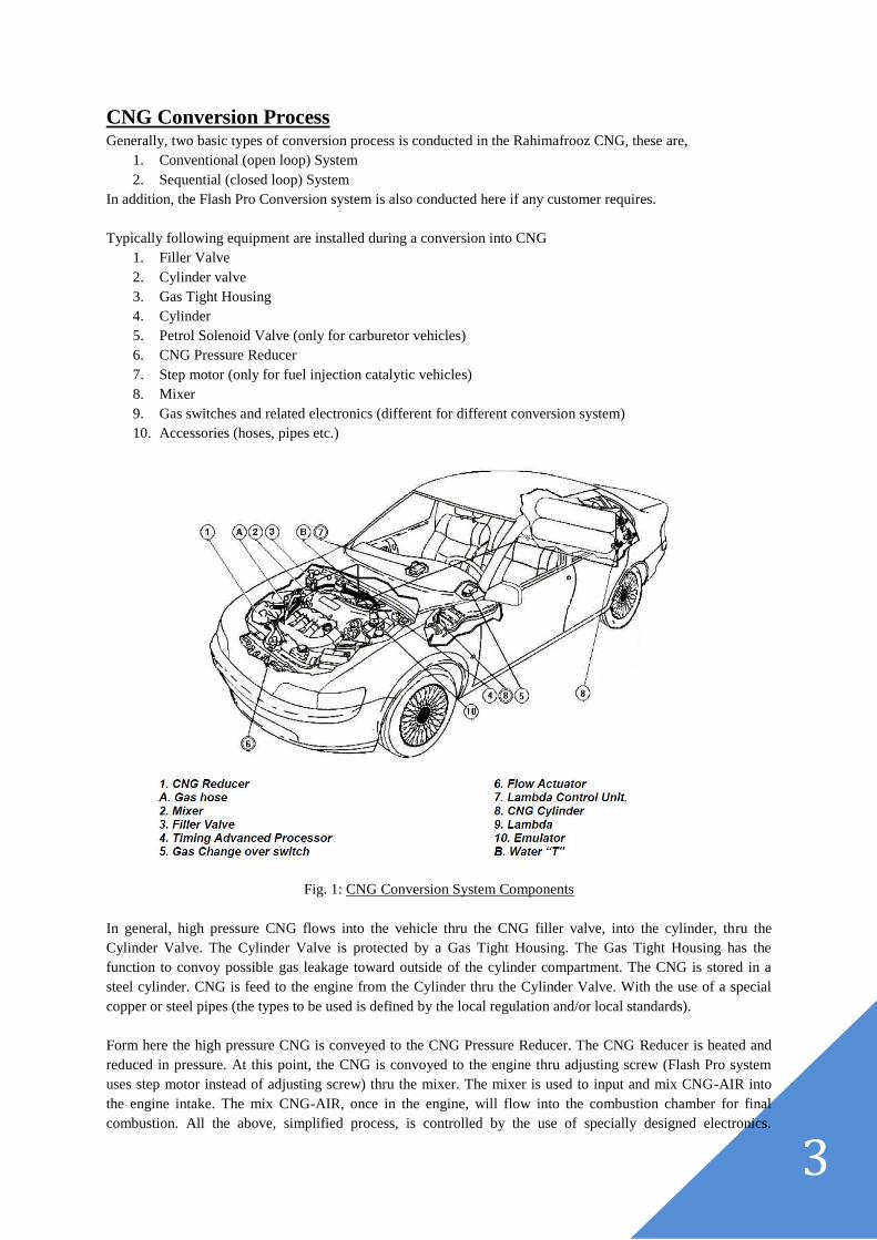
Fig. 1: CNG Conversion System Components
In general, high pressure CNG flows into the vehicle thru the CNG filler valve, into the cylinder, thru the
Cylinder Valve. The Cylinder Valve is protected by a Gas Tight Housing. The Gas Tight Housing has the
function to convoy possible gas leakage toward outside of the cylinder compartment. The CNG is stored in a
steel cylinder. CNG is feed to the engine from the Cylinder thru the Cylinder Valve. With the use of a special
copper or steel pipes (the types to be used is defined by the local regulation and/or local standards).
Form here the high pressure CNG is conveyed to the CNG Pressure Reducer. The CNG Reducer is heated and
reduced in pressure. At this point, the CNG is convoyed to the engine thru adjusting screw (Flash Pro system
uses step motor instead of adjusting screw) thru the mixer. The mixer is used to input and mix CNG-AIR into
the engine intake. The mix CNG-AIR, once in the engine, will flow into the combustion chamber for final
combustion. All the above, simplified process, is controlled by the use of specially designed electronics.
4
Components used during CNG Conversion
1. CNG Cylinder
CNG Cylinders for motor vehicles are manufactured in many lengths and diameters. The Cylinder is most
commonly manufactured with special steel alloys. In some cases its weight may be reduced thru a special
manufacturing process in which the steel thickness is reduced and covered with a coating of a special resin.
Rahimafrooz imported CNG cylinder mainly from Korea & Argentina.
Fig. 2: Typical CNG Cylinder
General Installation Place: Luggage Compartment
Standard Installation Procedure:
1. Installed with strong bracket covered with rubber
2. Attached with a wooden frame into the luggage compartment
3. Installed in such a way that the cylinder valve will be well apart from any instrument of the car or the
car body itself
2. CNG Filler Valve
The filler valve is a very simple item and is shaped to couple with the NGV filling nozzle. The filler valve has
the function of maintaining a gas tight condition during refilling procedure.
General Installation Place: Engine Compartment
Standard Installation Procedure:
1. Install far from any source of excessive heat (e.g. exhaust manifold)
2. Install far from the battery terminal
3. Install far from ignition coil and high tension coil
4. Use sealing tape to connect with high pressure pipe
3. Cylinder Valve
The Cylinder Valve is an important part of the Cylinder assembly. The Cylinder Valve is provided with a series
of safety devices; in some cases including the thermal fuse and the pressure plug.
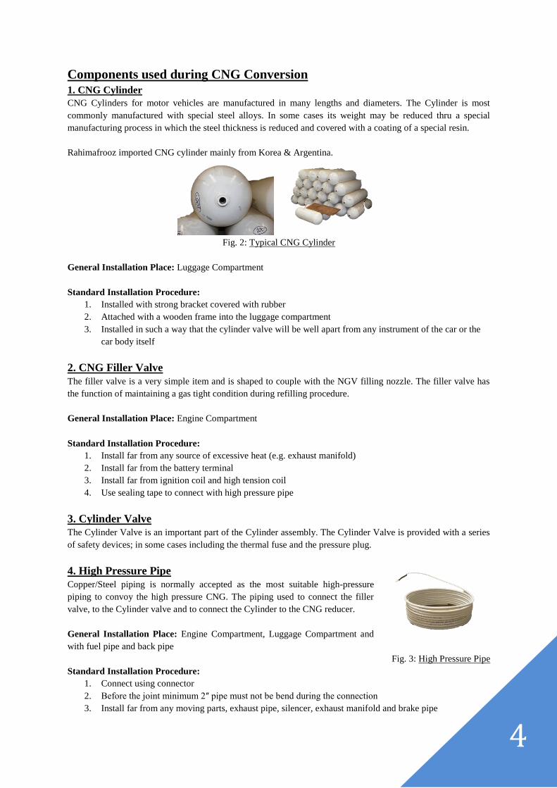
4. High Pressure Pipe
Copper/Steel piping is normally accepted as the most suitable high-pressure
piping to convoy the high pressure CNG. The piping used to connect the filler
valve, to the Cylinder valve and to connect the Cylinder to the CNG reducer.
General Installation Place: Engine Compartment, Luggage Compartment and
with fuel pipe and back pipe
Fig. 3: High Pressure Pipe
Standard Installation Procedure:
1. Connect using connector
2. Before the joint minimum 2ʺ pipe must not be bend during the connection
3. Install far from any moving parts, exhaust pipe, silencer, exhaust manifold and brake pipe
5
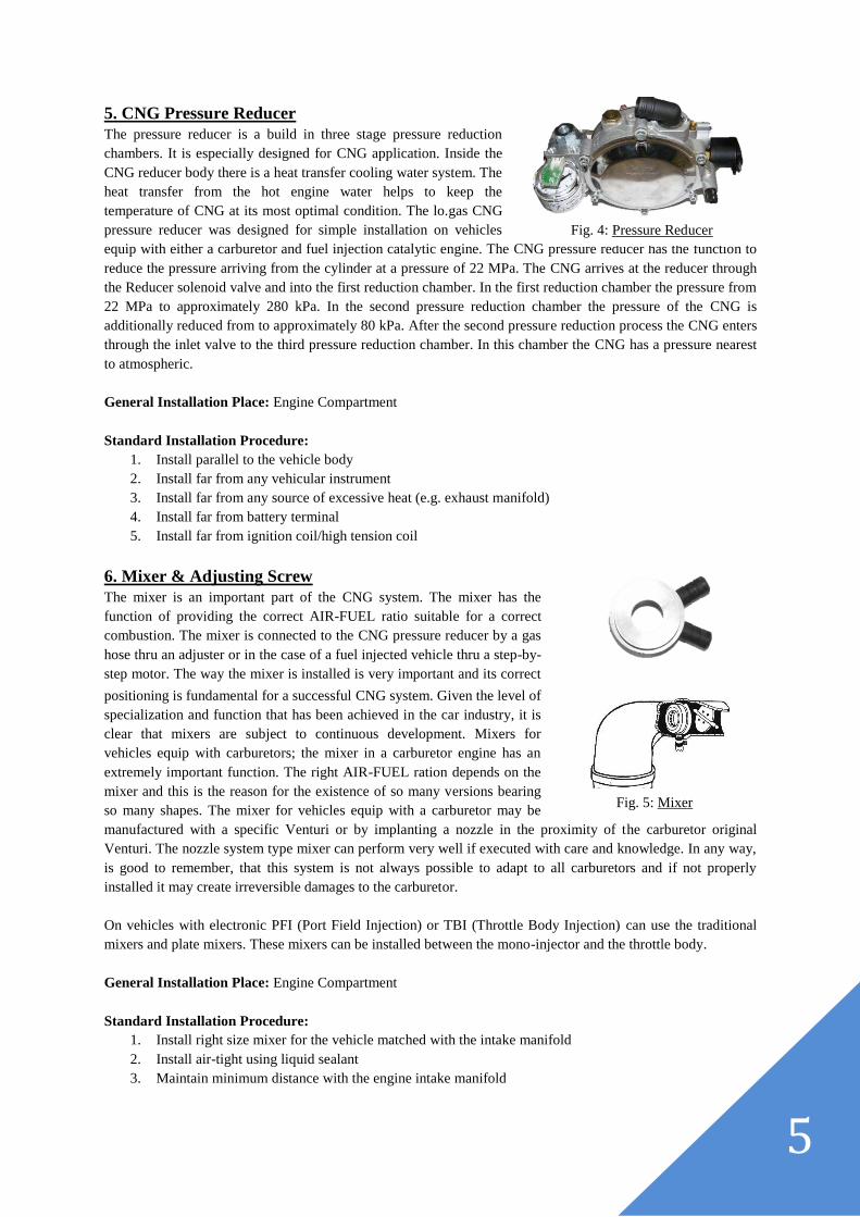
5. CNG Pressure Reducer
The pressure reducer is a build in three stage pressure reduction
chambers. It is especially designed for CNG application. Inside the
CNG reducer body there is a heat transfer cooling water system. The
heat transfer from the hot engine water helps to keep the
temperature of CNG at its most optimal condition. The lo.gas CNG
pressure reducer was designed for simple installation on vehicles
equip with either a carburetor and fuel injection catalytic engine. The CNG pressure reducer has the function to
reduce the pressure arriving from the cylinder at a pressure of 22 MPa. The CNG arrives at the reducer through
the Reducer solenoid valve and into the first reduction chamber. In the first reduction chamber the pressure from
22 MPa to approximately 280 kPa. In the second pressure reduction chamber the pressure of the CNG is
additionally reduced from to approximately 80 kPa. After the second pressure reduction process the CNG enters
through the inlet valve to the third pressure reduction chamber. In this chamber the CNG has a pressure nearest
to atmospheric.
General Installation Place: Engine Compartment
Standard Installation Procedure:
1. Install parallel to the vehicle body
2. Install far from any vehicular instrument
3. Install far from any source of excessive heat (e.g. exhaust manifold)
4. Install far from battery terminal
5. Install far from ignition coil/high tension coil
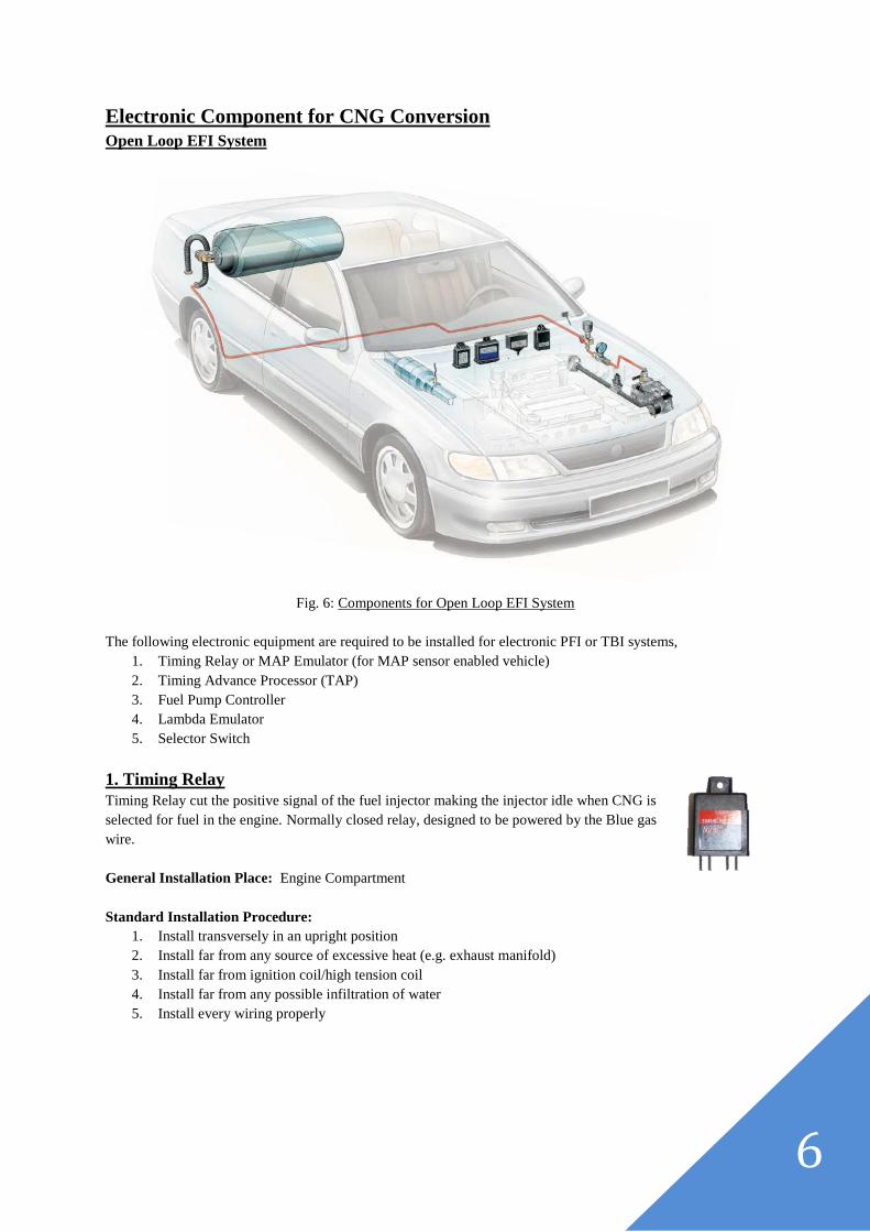
6. Mixer & Adjusting Screw
The mixer is an important part of the CNG system. The mixer has the
function of providing the correct AIR-FUEL ratio suitable for a correct
combustion. The mixer is connected to the CNG pressure reducer by a gas
hose thru an adjuster or in the case of a fuel injected vehicle thru a step-by-
step motor. The way the mixer is installed is very important and its correct
positioning is fundamental for a successful CNG system. Given the level of
specialization and function that has been achieved in the car industry, it is
clear that mixers are subject to continuous development. Mixers for
vehicles equip with carburetors; the mixer in a carburetor engine has an
extremely important function. The right AIR-FUEL ration depends on the
mixer and this is the reason for the existence of so many versions bearing
so many shapes. The mixer for vehicles equip with a carburetor may be
manufactured with a specific Venturi or by implanting a nozzle in the proximity of the carburetor original
Venturi. The nozzle system type mixer can perform very well if executed with care and knowledge. In any way,
is good to remember, that this system is not always possible to adapt to all carburetors and if not properly
installed it may create irreversible damages to the carburetor.
On vehicles with electronic PFI (Port Field Injection) or TBI (Throttle Body Injection) can use the traditional
mixers and plate mixers. These mixers can be installed between the mono-injector and the throttle body.
General Installation Place: Engine Compartment
Standard Installation Procedure:
1. Install right size mixer for the vehicle matched with the intake manifold
2. Install air-tight using liquid sealant
3. Maintain minimum distance with the engine intake manifold
Fig. 4: Pressure Reducer
Fig. 5: Mixer
6
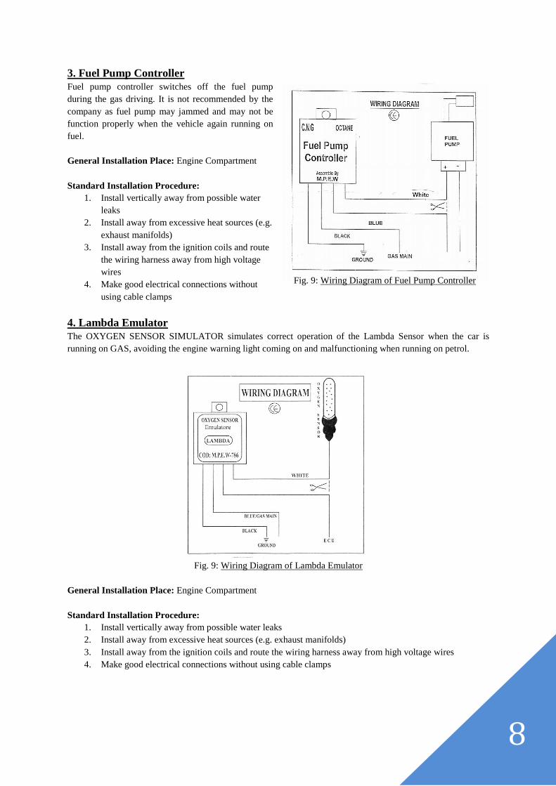
Electronic Component for CNG Conversion
Open Loop EFI System
Fig. 6: Components for Open Loop EFI System
The following electronic equipment are required to be installed for electronic PFI or TBI systems,
1. Timing Relay or MAP Emulator (for MAP sensor enabled vehicle)
2. Timing Advance Processor (TAP)
3. Fuel Pump Controller
4. Lambda Emulator
5. Selector Switch
1. Timing Relay
Timing Relay cut the positive signal of the fuel injector making the injector idle when CNG is
selected for fuel in the engine. Normally closed relay, designed to be powered by the Blue gas
wire.
General Installation Place: Engine Compartment
Standard Installation Procedure:
1. Install transversely in an upright position
2. Install far from any source of excessive heat (e.g. exhaust manifold)
3. Install far from ignition coil/high tension coil
4. Install far from any possible infiltration of water
5. Install every wiring properly

7
2. Timing Advance Processor (TAP)
Electronic timing advance processor that can be installed on 3-4-5-6 and 8 cylinder cars fitted with an injection-
ignition system with an inductive type PMS sensor. It can automatically adjust the advance timing, improve
performance, and reduce consumptions and the risk of "backfiring".
Fig. 7: Wiring Diagram for Timing Advance Processor (Cobra AEB510N)
General Installation Place: Engine Compartment
Standard Installation Procedure:
1. Install vertically away from possible water leaks
2. Install away from excessive heat sources (e.g. exhaust manifolds)
3. Install away from the ignition coils and route the wiring harness away from high voltage wires
4. Make good electrical connections without using cable clamps
MAP Emulator
Emulator used instead of the timing advance processor for vehicles built before 2000, and on which the timing
advance processor cannot be installed. This emulator may be installed on vehicles with a MAP sensor to modify
and optimize the advance curve for the vehicle. Installation is facilitated by the original connectors being used
for the connection. In this way the original wiring is not tampered with.
It increases performance, eliminates sudden drops in timing during acceleration, thereby avoiding backfiring and
gaps in acceleration.
By installing the M.A.P. Emulator, even if the car has been converted to natural gas, you can avoid installing the
Timing Advance Converter.
Fig. 8: Wiring Diagram of MAP Emulator
8
3. Fuel Pump Controller
Fuel pump controller switches off the fuel pump
during the gas driving. It is not recommended by the
company as fuel pump may jammed and may not be
function properly when the vehicle again running on
fuel.
General Installation Place: Engine Compartment
Standard Installation Procedure:
1. Install vertically away from possible water
leaks
2. Install away from excessive heat sources (e.g.
exhaust manifolds)
3. Install away from the ignition coils and route
the wiring harness away from high voltage
wires
4. Make good electrical connections without
using cable clamps
4. Lambda Emulator
The OXYGEN SENSOR SIMULATOR simulates correct operation of the Lambda Sensor when the car is
running on GAS, avoiding the engine warning light coming on and malfunctioning when running on petrol.
Fig. 9: Wiring Diagram of Lambda Emulator
General Installation Place: Engine Compartment
Standard Installation Procedure:
1. Install vertically away from possible water leaks
2. Install away from excessive heat sources (e.g. exhaust manifolds)
3. Install away from the ignition coils and route the wiring harness away from high voltage wires
4. Make good electrical connections without using cable clamps
Fig. 9: Wiring Diagram of Fuel Pump Controller
9
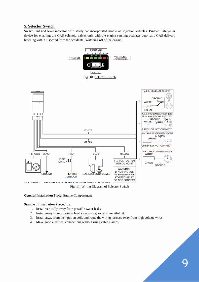
5. Selector Switch
Switch unit and level indicator with safety car incorporated usable on injection vehicles. Built-in Safety-Car
device for enabling the GAS solenoid valves only with the engine running activates automatic GAS delivery
blocking within 1 second from the accidental switching off of the engine.
Fig. 10: Selector Switch
Fig. 11: Wiring Diagram of Selector Switch
General Installation Place: Engine Compartment
Standard Installation Procedure:
1. Install vertically away from possible water leaks
2. Install away from excessive heat sources (e.g. exhaust manifolds)
3. Install away from the ignition coils and route the wiring harness away from high voltage wires
4. Make good electrical connections without using cable clamps
10
Closed Loop (Sequential Injection) EFI System
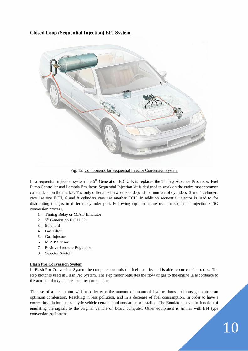
Fig. 12: Components for Sequential Injector Conversion System
In a sequential injection system the 5th
Generation E.C.U Kits replaces the Timing Advance Processor, Fuel
Pump Controller and Lambda Emulator. Sequential Injection kit is designed to work on the entire most common
car models ion the market. The only difference between kits depends on number of cylinders: 3 and 4 cylinders
cars use one ECU, 6 and 8 cylinders cars use another ECU. In addition sequential injector is used to for
distributing the gas in different cylinder port. Following equipment are used in sequential injection CNG
conversion process,
1. Timing Relay or M.A.P Emulator
2. 5th
Generation E.C.U. Kit
3. Solenoid
4. Gas Filter
5. Gas Injector
6. M.A.P Sensor
7. Positive Pressure Regulator
8. Selector Switch
Flash Pro Conversion System
In Flash Pro Conversion System the computer controls the fuel quantity and is able to correct fuel ratios. The
step motor is used in Flash Pro System. The step motor regulates the flow of gas to the engine in accordance to
the amount of oxygen present after combustion.
The use of a step motor will help decrease the amount of unburned hydrocarbons and thus guarantees an
optimum combustion. Resulting in less pollution, and in a decrease of fuel consumption. In order to have a
correct installation in a catalytic vehicle certain emulators are also installed. The Emulators have the function of
emulating the signals to the original vehicle on board computer. Other equipment is similar with EFI type
conversion equipment.
11
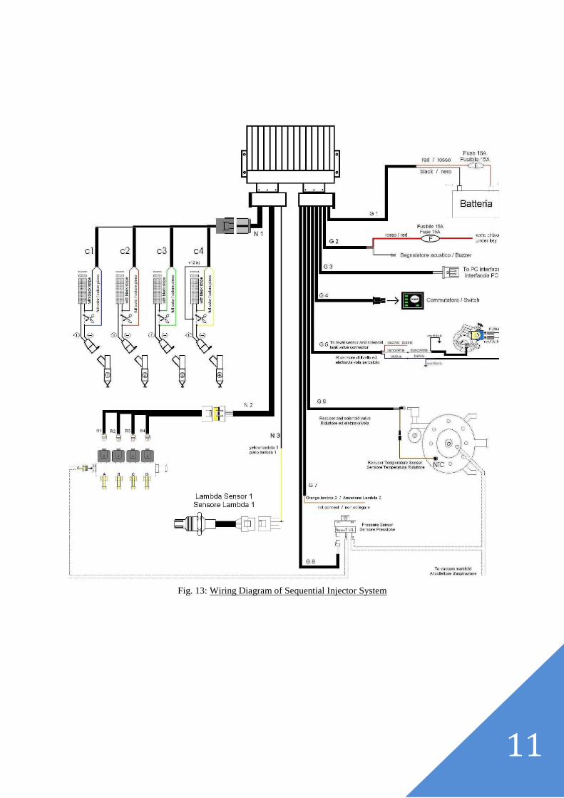
Fig. 13: Wiring Diagram of Sequential Injector System
12
Carburetor System
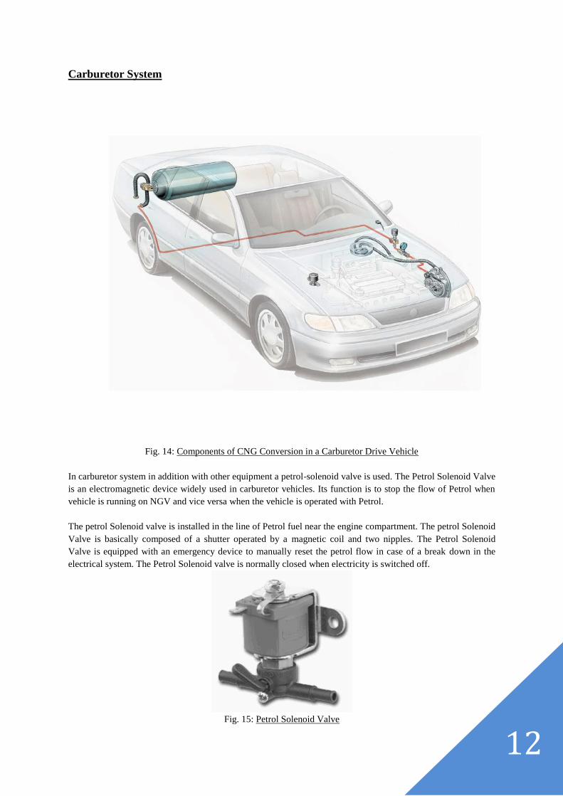
Fig. 14: Components of CNG Conversion in a Carburetor Drive Vehicle
In carburetor system in addition with other equipment a petrol-solenoid valve is used. The Petrol Solenoid Valve
is an electromagnetic device widely used in carburetor vehicles. Its function is to stop the flow of Petrol when
vehicle is running on NGV and vice versa when the vehicle is operated with Petrol.
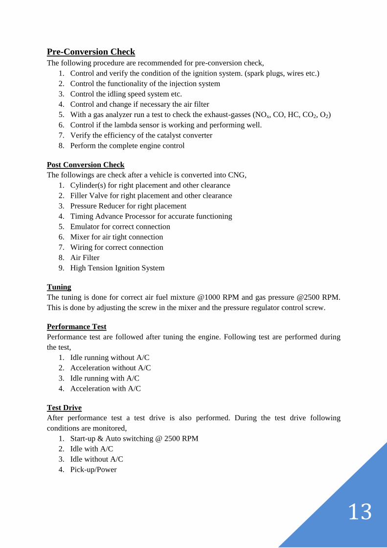
The petrol Solenoid valve is installed in the line of Petrol fuel near the engine compartment. The petrol Solenoid
Valve is basically composed of a shutter operated by a magnetic coil and two nipples. The Petrol Solenoid
Valve is equipped with an emergency device to manually reset the petrol flow in case of a break down in the
electrical system. The Petrol Solenoid valve is normally closed when electricity is switched off.
Fig. 15: Petrol Solenoid Valve
13
Pre-Conversion Check
The following procedure are recommended for pre-conversion check,
1. Control and verify the condition of the ignition system. (spark plugs, wires etc.)
2. Control the functionality of the injection system
3. Control the idling speed system etc.
4. Control and change if necessary the air filter
5. With a gas analyzer run a test to check the exhaust-gasses (NOx, CO, HC, CO2, O2)
6. Control if the lambda sensor is working and performing well.
7. Verify the efficiency of the catalyst converter
8. Perform the complete engine control
Post Conversion Check
The followings are check after a vehicle is converted into CNG,
1. Cylinder(s) for right placement and other clearance
2. Filler Valve for right placement and other clearance
3. Pressure Reducer for right placement
4. Timing Advance Processor for accurate functioning
5. Emulator for correct connection
6. Mixer for air tight connection
7. Wiring for correct connection
8. Air Filter
9. High Tension Ignition System
Tuning
The tuning is done for correct air fuel mixture @1000 RPM and gas pressure @2500 RPM.
This is done by adjusting the screw in the mixer and the pressure regulator control screw.
Performance Test
Performance test are followed after tuning the engine. Following test are performed during
the test,
1. Idle running without A/C
2. Acceleration without A/C
3. Idle running with A/C
4. Acceleration with A/C
Test Drive
After performance test a test drive is also performed. During the test drive following
conditions are monitored,
1. Start-up & Auto switching @ 2500 RPM
2. Idle with A/C
3. Idle without A/C
4. Pick-up/Power
14
Recommendations:
The following improvement can be done for further development,
1. CNG cylinder test facility can be developed
2. Manual tuning process can be tested further using sensor based monitoring system
3. More advanced electronics from AEB can be imported to check the E.C.U.
malfunctioning in some occasions where Timing Relay is used
4. Further modifications or development can be done to check the problem when the
vehicle A/C is operated
5. More feedback system can be attached to make the drive smooth with vehicle E.C.U
6. Further electronics can be attached for the catalytic fuel injected system to keep the
environment clean
7. More underground house for connecting the high pressure line below the vehicle can
be constructed for rapid conversion
References:
1. CNG Conversion General Manual, lo.gas, Updated January, 2001
2. Standard Operating Procedure, Rahimafrooz CNG Ltd., No. CSC-SOP-04, May, 2005
3. Pre Conversion Inspection Report, Rahimafrooz CNG Ltd.
4. Post Conversion Check List, Rahimafrooz CNG Ltd., F8206, Rev 01
5. Assembly Instruction Manual, Code 725A, AEB
6. Assembly Instruction Manual, Code AEB466, AEB
7. Fitting Instructions and Warranty Workbook, Code AEB510N
8. Fitting Instructions and Warranty Workbook, Code AEB515N
9. Fitting Instructions, Code 462/2, AEB
10. Lo.gas Injection System, Manual 8KI00008
11. Instruction Manual 2° Injection System, Lo.gas
12. Conversion Press Release, NGVAmerica, May 2008
13. Landirenzo Omega Plus, Natural Gas Multipoint Injection System, Manual
14. NGV Mixer System, Landirenzo, Manual
15. Toyota Corolla Owner’s Manual, 2006
16. Honda Civic Owner’s Manual, 2004
17. Wiring Diagram, Toyota Corolla, 2006
Recommended