Radiobiology with laser-driven electron accelerators
L. Labate1,1,22, M.G. Andreassi33, F. Baffigi11, R. Bizzarri44, A. Borghini33, G. Bussolino11, G. Candiano55, C. Casarino55, F. Di Martino66, L. Fulgentini11, P. Koester11, F. Ghetti44, M.C. Gilardi55, A. Giulietti11,
D. Lamia55, T. Levato11, G. Russo55, A. Sgarbossa44, C. Traino66, L.A. Gizzi1,1,22
11 ILIL, Istituto Nazionale di Ottica, Consiglio Nazionale delle Ricerche, Pisa, Italy22 Istituto Nazionale di Fisica Nucleare, Sezione di Pisa e Laboratori Nazionali di Frascati, Italy33 Istituto di Fisiologia Clinica, Consiglio Nazionale delle Ricerche, Pisa, Italy44 Istituto di Nanoscienze, Consiglio Nazionale delle Ricerche, Pisa, Italy55 Laboratorio di Tecnologie Oncologiche HSR-Giglio, Istituto di Bioimmagini e Fisiologia Molecolare, Consiglio Nazionale delle Ricerche, Cefalu', Italy66 U.O. Fisica Sanitaria, Azienda Ospedaliero-Universitaria Pisana, Pisa, Italy
The Intense Laser Irradiation Laboratory group
http://ilil.ino.it
Main fields- Laser-driven acceleration of electrons and related secondary sources- Laser-plasma interaction studies relevant for ICF
PEOPLEPEOPLE• Leonida A. GIZZI (CNR)* (Resp.)Leonida A. GIZZI (CNR)* (Resp.)
• Giancarlo BUSSOLINO (CNR)Giancarlo BUSSOLINO (CNR)
• Gabriele CRISTOFORETTI (CNR)Gabriele CRISTOFORETTI (CNR)
• Luca LABATE (CNR)*Luca LABATE (CNR)*
• Fernando BRANDI (CNR), Ric. TD.Fernando BRANDI (CNR), Ric. TD.
• Petra KOESTER (CNR), Ric. Contr.Petra KOESTER (CNR), Ric. Contr.
• Tadzio LEVATO (CNR), Ric. Contr.Tadzio LEVATO (CNR), Ric. Contr.
• Federica BAFFIGI (CNR), A.R.Federica BAFFIGI (CNR), A.R.
• Paolo FERRARA (CNR), A. R.Paolo FERRARA (CNR), A. R.
• Lorenzo FULGENTINI (CNR), A.R.Lorenzo FULGENTINI (CNR), A.R.
• Antonio GIULIETTI(CNR), AssocAntonio GIULIETTI(CNR), Assoc
• Danilo GIULIETTI (Univ. Pisa), Ass.*Danilo GIULIETTI (Univ. Pisa), Ass.*
• Daniele PALLA, PhD student *Daniele PALLA, PhD student *
• Antonella ROSSI (CNR) – Tech.Antonella ROSSI (CNR) – Tech.
** Also at INFN Also at INFN

Outline
Overview of the Laser WakeField (LWFA) technique
Why using LWFA for radiotherapy
A taste of the first radiobiology studies with LWF-accelerated electrons

The Laser WakeField Acceleration concept
How to create a high amplitude plasma wave?• Ponderomotive force (laser pulse)
• Coulomb force (charged particle bunches)
Laser Wakefield Acceleration use the first approach, made possible by ultrashort and ultraintense laser pulses
Electron plasma waves meet the requirements for charged particle acceleration:- intense longitudinal electric fields- phase velocity close to the speed of light
Analogy witha surfer
Laser pulse
F≈-grad I
Electron density perturbation
Analogy witha boat

RF-based vs. laser-driven plasma accelerators
Classical (RF-based) accelerators limits
Maximum E-field ~few tens of MV/m (due to breakdown)
Synchrotron radiation losses large radius→
Laser-driven plasma accelerators
Plasma is an ionized medium no structural limits to the E-field→
Electric field amplitude in a plasma wave: E~ √nE ~ 0.3 GV/m for 1% density perturbation at n ~ 1017cm-3
E ~ 300 GV/m for 100% density perturbation at n ~ 1019 cm-3

LWFA: the basic setup and “accelerator” footprint
Gas-jetnozzle
Laser
e- bunch
Basic arrangementThe laser pulse is focused in
the proximity of the entrance edge of the gas-jet
Electrons are accelerated in the forward direction

A glance at the (now “historical”) literature
1979: proposal by Tajima&Dawson2004: “Dream
beam” front cover of Nature (3 papers
reporting “high-quality” e- bunch
production)
2006: GeV energy reported
End of noughties: routine production of stable e- bunch
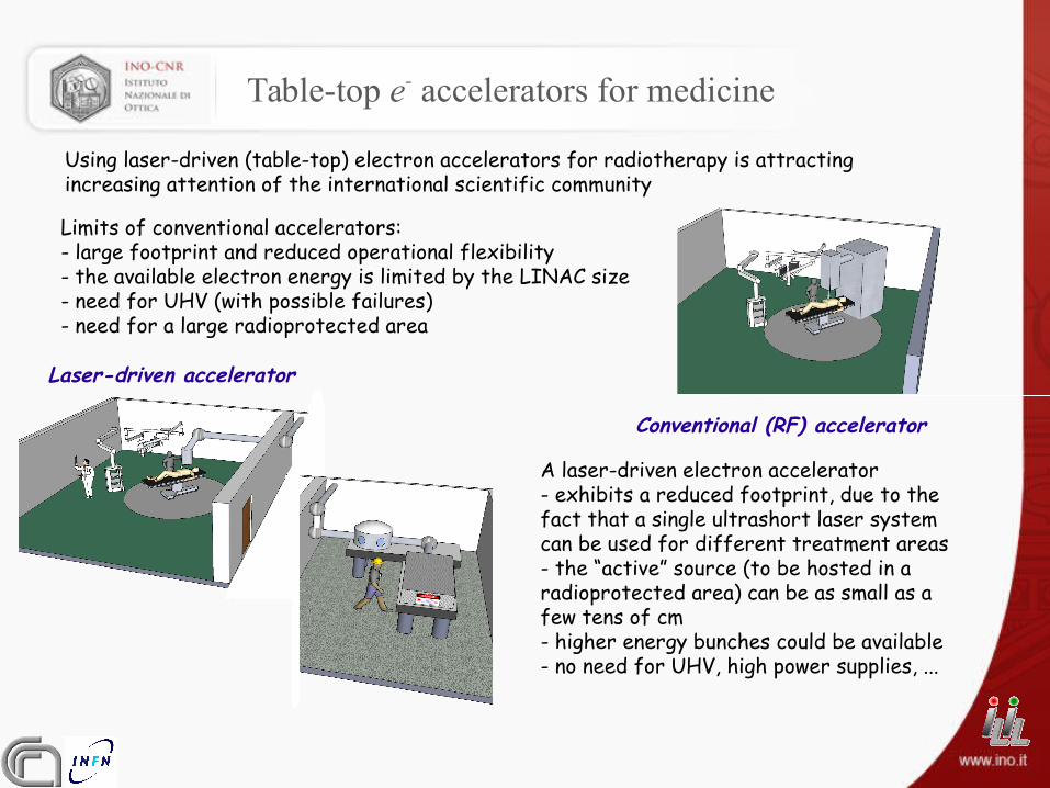
Table-top e- accelerators for medicine
Using laser-driven (table-top) electron accelerators for radiotherapy is attracting increasing attention of the international scientific community
Conventional (RF) accelerator
Laser-driven accelerator
Limits of conventional accelerators:- large footprint and reduced operational flexibility- the available electron energy is limited by the LINAC size- need for UHV (with possible failures)- need for a large radioprotected area
A laser-driven electron accelerator- exhibits a reduced footprint, due to the fact that a single ultrashort laser system can be used for different treatment areas- the “active” source (to be hosted in a radioprotected area) can be as small as a few tens of cm- higher energy bunches could be available- no need for UHV, high power supplies, ...

Conventional vs. laser-driven e- bunches
Comparable figures as for electron energy, bunch charge, rep rate, average current
Bunch duration ( peak →current) of laser-driven accelerators much shorter
An assessment of the effects of such high-current e- bunches on biological samples is needed at a pre-clinical stage(and new applications in perspectives?)
Biological Effects of laser-accelerated Electrons for Medicine

Setup for irradiation of in-vitro bio-samples @ILIL
e- bunch
Gas-jet target
Driver laser beam
Bio samples position
Biological samples are irradiated in air
An ad hoc “collimator” and vacuum-air window for the e- bunches were designed, simulated and tested using GEANT4
The e- bunch was fully characterized, in terms of energy, charge and divergence by means of calibrated stacks of RadioChromic Film detectors and MonteCarlo simulations

Typical e- spectrum and beam transverse profile
Typical spectrum selected for radiobiology studies extends up to ~20MeVHowever, dosimetric measurements and comparison with GEANT4 simulations show that a strong low-energy (~MeV) component exists
The transverse profile of the dose distribution in air shows a variation of the order of 10% across a 20mm size spatial region

Dosimetric characterization
The dose/shot on the sample was retrieved by comparing experimental measurements performed using suitable stacks of GAFchromic films with GEANT4 MonteCarlo simulations of the electron beam transport/interactions
Retrieved dose ~100mGy/shot Cumulated doses up to 1 – 10 Gy were provided at 1Hz rep rate in a few 10s of seconds
Scattering/interactions processes make the bunch last for a few picoseconds at the sample position
Example of DNA damage studies
0
20
40
60
80
100
0 1 2 3 4 5
First donor (male)
Baseline 0.1 0.2 0.5 1 2
MN
/100
0 ce
lls
p=0.04
p=0.004
p=0.001
p<0.001
Dose (Gy)
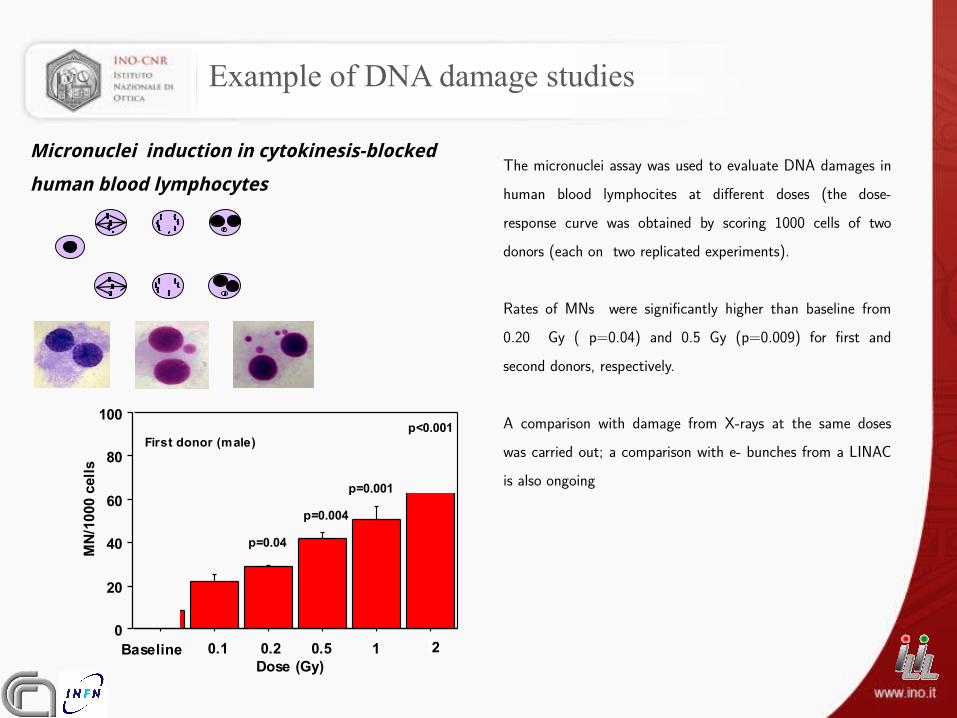
The micronuclei assay was used to evaluate DNA damages in human blood lymphocites at different doses (the dose-response curve was obtained by scoring 1000 cells of two donors (each on two replicated experiments).
Rates of MNs were significantly higher than baseline from 0.20 Gy ( p=0.04) and 0.5 Gy (p=0.009) for first and second donors, respectively.
A comparison with damage from X-rays at the same doses was carried out; a comparison with e- bunches from a LINAC is also ongoing
Micronuclei induction in cytokinesis-blocked
human blood lymphocytes
Example of membrane damage studies [1/2]
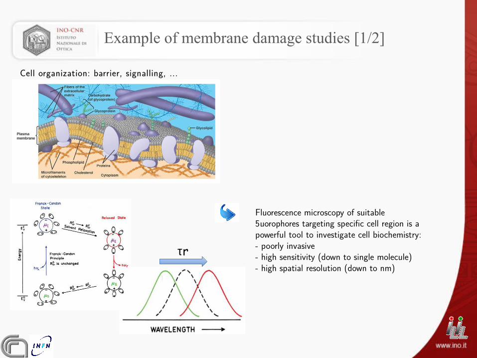
Cell organization: barrier, signalling, ...
Fluorescence microscopy of suitable fluorophores targeting specific cell region is a powerful tool to investigate cell biochemistry:- poorly invasive- high sensitivity (down to single molecule)- high spatial resolution (down to nm)
τr
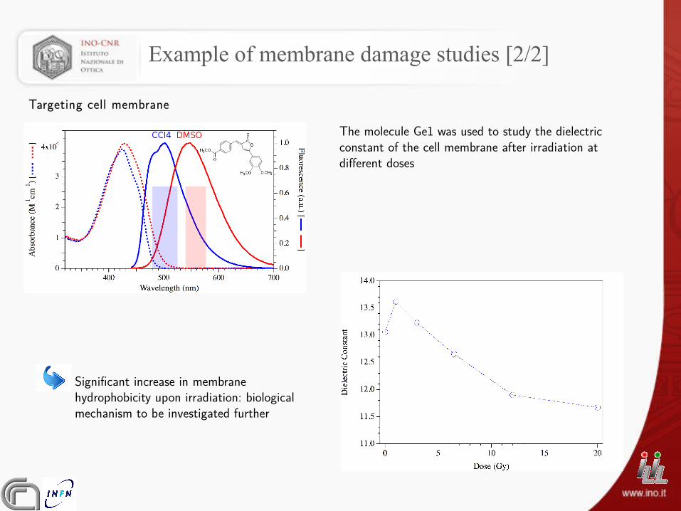
Example of membrane damage studies [2/2]
The molecule Ge1 was used to study the dielectric constant of the cell membrane after irradiation at different doses
Significant increase in membrane hydrophobicity upon irradiation: biological mechanism to be investigated further
Targeting cell membrane

Summary and conclusions
Laser-driven electron accelerators (based on the Laser WakeField Acceleration concept) have now entered a mature phase and are rapidly going toward real applications in medicine (in particular, radiotherapy)
The group operating at the ILIL laboratory is carrying out a long term study of laser-driven electron accelerators and high energy photon sources based on them
In particular, a project is ongoing aimed at assessing, at a pre-clinical stage, the possibility of using small-scale, TW-class laser systems to produce electron bunches at a few tens of MeV energy, of interest for radiotherapy
An ad hoc setup has been studied, simulated and tested, allowing irradiation of in vitro samples in air
The first tests show a biological response similar to the one expected from the literature for irradiation using conventional (RF linacs) electron bunches

The ILIL laboratory
Laser main figures-energy: up to 450mJ on target-pulse duration <40fs-ASE contrast > 109
-M2 < 1.5-intensity: up to 2x10¹⁹ W/cm2
Target area equipment-2 “dedicated” vacuum chambers (“gas-jet”
and “solid” targets)-optical and X-ray diagnostics
-electron diagnostics-integrated environment for diagnostic data
automatic collection
Recommended