BELL SYSTEM PRACTICES
Plant Series
SECTION 500-150-1 00
Issue 6, April 1970
AT&TCa Standard
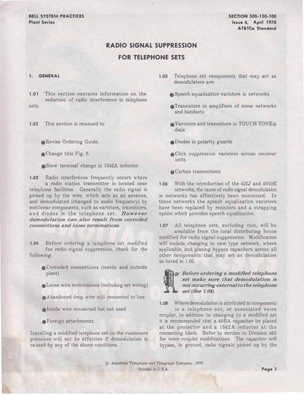
RADIO SIGNAL SUPPRESSION
FOR TELEPHONE SETS
1. GENERAL
1.01 This section contains information on the reduction of radio interference in telephone
sets.
1.02 This section is reissued to:
eRevise Ordering Guide.
eChange title Fig. 6.
eShow terminal change in 1542A inductor
1.03 Radio interference frequently occurs where a radio station transmitter is located near
telephone facilities. Generally the radio signal is picked up by the wire, which acts as an antenna, and demodulated (changed to audio frequency) by nonlinear components, such as varistors, transistors, a n d diodes in the telephone set. However demodulation can also result from corroded connections and loose terminations.
1.04 Before ordering a telephone set modified for radio signal suppression, check for the
following:
eCorroded connections (inside and outside plant)
eLoose wire terminations (including set wiring)
eAbandoned drop wire still connected to line
einside wire connected but not used
eForeign attachments.
Installing a modified telephone set on the customers premises will not be effective if demodulation is caused by any of the above conditions.
1.05 Telephone set components that may act as demodulators are:
e Speech equalization varistors in networks
eTransistors in amplifiers of some networks and handsets
e Varistors and transistors in TOUCH-TONE® dials
eDiodes in polarity guards
eClick suppression varistors across receiver units
eCarbon transmitters
1.06 With the introduction of the 425J and 4010E networks, the cause of radio signal demodulation
in networks has effectively been minimized. In these networks the speech equalization varistors have been replaced by resistors and a strapping option which provides speech equalization.
1.07 All telephone sets, excluding coin, will be available from the local distributing house
modified for radio signal suppression. Modification will include changing to new type network, where applicable, and placing bypass capacitors across all other components that may act as demodulators as listed in 1.05.
Before ordering a modified telephone set make sure that demodulation is not occurring external to the telephone set (See 1.04).
1.08 Where demodulation is attributed to components in a telephone set, or associated voice
coupler, in addition to changing to a modified set it is recommended that a 40BA capacitor be placed at the protector and a 1542A inductor at the connecting block. Refer to section in Division 463 for voice coupler modifications. The capacitor will bypass, to ground, radio signals picked up by the
@ American Telephone and Telegraph Company, 1�70
Printed in U.S.A. Page 1
SECTION S00-150-100
drop wire while the inductor will tend to attenuate radio signals picked up by the inside wire.
1.09 Where an adjunct (TOUCH-TONE) dial forms a part of the customers equipment and a
modified telephone set is installed for radio interference reasons, the adjunct dial should also be replaced by one modified for radio suppression.
1.10 MD telephone sets will not be modified for radio suppression. Where a telephone set
rated MD is encountered, it should be replaced by an equivalent set in the current series, modified for radio suppression.
1.11 If possible, arrange for operation of the radio station during the trouble visit in order that
the effectiveness of corrective measures taken may be evaluated immediately.
2. IDENTIFICATION
2.01 Suppression Devices
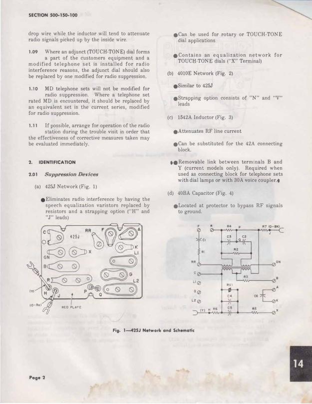
(a) 425J Network (Fig. 1)
eEiiminates radio interference by having the speech equalization varistors replaced by resistors and a strapping option (" H" and "J" leads)
C � RR F�O'�A 0� 425J �0�
� � K �@::ox �LI
� :� C3)) -� ((;_� G R� � L2
'" r1L ,�Q�
(O·B�I� REO PLATE
eCan be used for rotary or TOUCH-TONE dial applications
eContains an e qu alization netw ork for TOUCH-TONE dials ("X" Terminal)
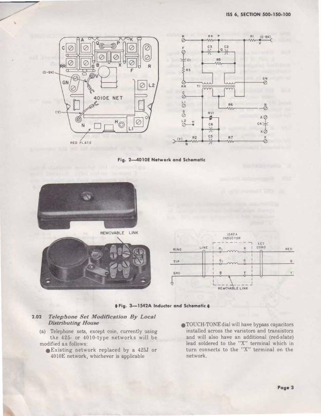
(b) 4010E Network (Fig. 2)
eSimilar to 425J
eStrapping option consists of "N" and "V" leads
(c) 1542A Inductor (Fig. 3)
eAttenuates RF line current
eCan be substituted for the 42A connecting block.
••Removable link between terminals B and Y (current models only). Required when used as connecting block for telephone sets with dial lamps or with 30A voice coupler .•
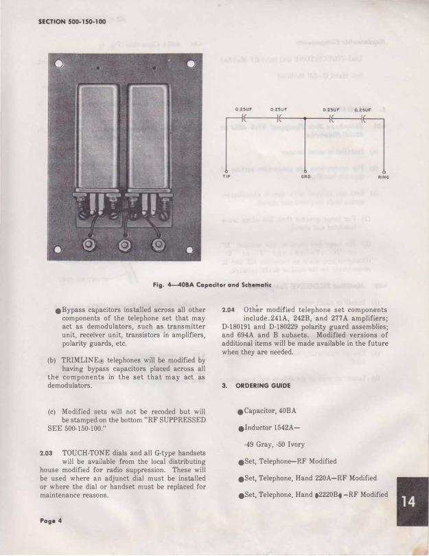
(d) 40BA Capacitor (Fig. 4)
eLocated at protector to bypass RF signals to ground.
Fig. 1--425J Network and Schematic
Page 2
(0-BKI
RR
Ll
0 G
0
�
RED PLATE
R4 P
ISS 6, SECTION 500-150-100
Rl (0-BKI
v
GN
Fig. 2-4010E Network and Schematic
RING
TIP
GRO
1542A INDUCTOR
r ----- - - I SET LINE I Rl R I CORD
I I B Y
L ___ \ ____ J REMOVABLE LINK
REO
y
• Fig. 3-1542A lndudor and Schematic t
2.02 Telephone Set Modification By Local Distributing House
(a) Telephone sets, except coin, currently using the 425- or 4010-type networks will be
modified as follows: eExisting network replaced by a 425J or
4010E network, whichever is applicable
eTOUCH-TONE dial will have bypass capacitors installed across the varistors and transistors and will also have an additional (red-slate) lead soldered to the "X" terminal which in turn connects to the "X" terminal on the network.
Page 3
SECTION 500-150-1 00
0.25UF 0.25UF 0.25UF 0.25UF
TIP GRO RING
Fig. 4-40BA Capacitor and Schematic
eBypass capacitors installed across all other components of the telephone set that may act as demodulators, such as transmitter unit, receiver unit, transistors in amplifiers, polarity guards, etc.
(b) TRIMLINE® telephones will be modified by having bypass capacitors placed across all
the components in the set that may act as demodulators.
(c) Modified sets will not be recoded but will be stamped on the bottom "RF SUPPRESSED
SEE 500-150-100."
2.03 TOUCH-TONE dials and all G-type handsets will be available from the local distributing
house modified for radio suppression. These will be used where an adjunct dial must be installed or where the dial or handset must be replaced for maintenance reasons.
Page 4
2.04 Other modified telephone set components include. 241A, 242B, and 277A amplifiers;
D-180191 and D-180229 polarity guard assemblies; and 694A and B subsets. Modified versions of additional items will be made available in the future when they are needed.
3. ORDERING GUIDE
eCapacitor, 40BA
einductor 1542A-
-49 Gray, -50 Ivory
eSet, Telephone-RF Modified
eSet, Telephone, Hand 220A-RF Modified
eSet, Telephone, Hand .2220B. -RF Modified
Replaceable Components
Dial-(TOUCH-TONE dial only) RF Modified
Set, Hand G--RF Modified
4. INSTALLATION
4.01 Telephone Sets Equipped With 425J or 40IOE Networks
(a) Installed in usual manner
(b) For connections see connection section of type set modified
(c) Sets are shipped with speech equalization option leads insulated and stored:
(1) For loops greater than 500 ohms leave insulated and stored.
(2) For loops 500 ohms or less connect "H" o r "N" ( Y e ll o w ) a n d "J" o r "V"
(Orange-Black) leads to terminals RR and R, respectively, on the 425J or 4010E network.
4.02 Modified TRIMLINE Telephones
(a) Install in usual manner
(b) See section in Division 502 for connections.
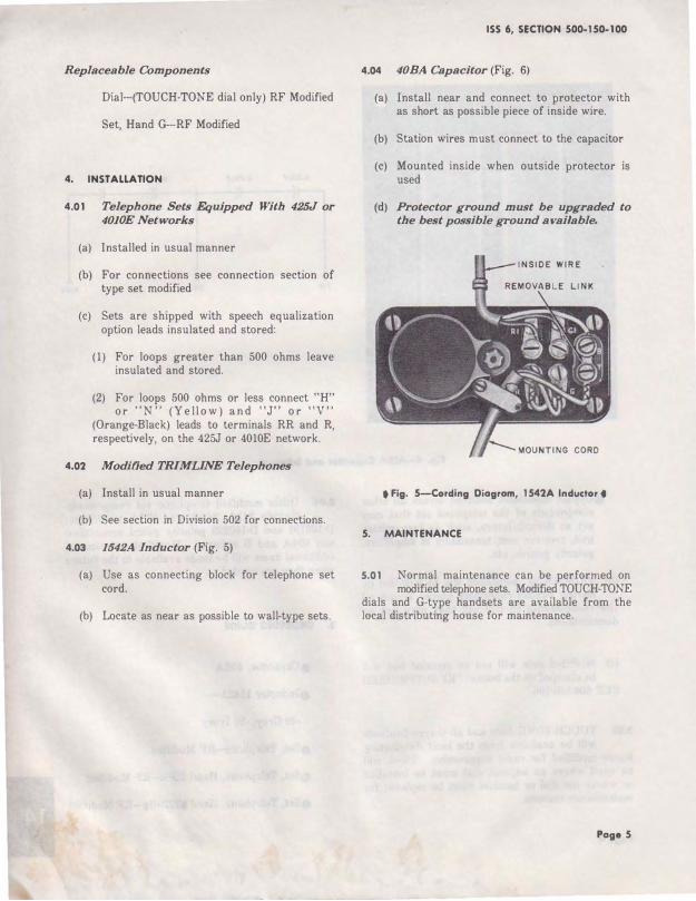
4.03 1542A Inductor (Fig. 5)
(a) Use as connecting block for telephone set cord.
(b) Locate as near as possible to wall-type sets.
ISS 6, SECTION 500-150-100
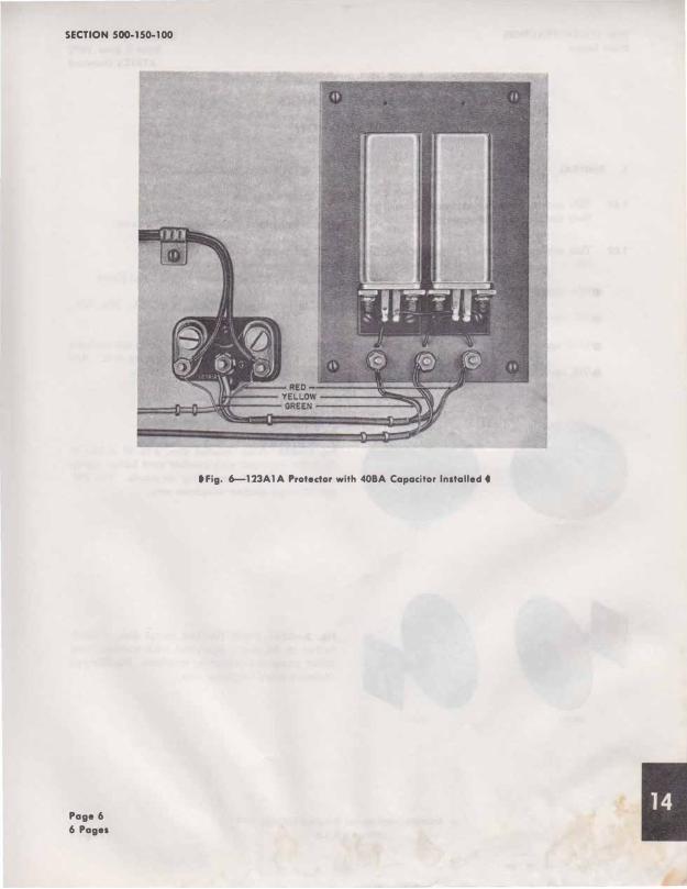
4.04 40BA Capacitor (Fig. 6)
(a) Install near and connect to protector with as short as possible piece of inside wire.
(b) Station wires must connect to the capacitor
(c) Mounted inside when outside protector is used
(d) Protector ground must be upgraded to the best possible ground available.
• Fig. 5-Cording Diogrom, 1542A Inductor •
5. MAINTENANCE
5.01 Normal maintenance can be performed on modified telephone sets. Modified TOUCH-TONE
dials and G-type handsets are available from the local distributing house for maintenance.
Poge 5
SECTION 500-150-100
Page 6
6 Pages
•Fig. 6-123A1A Protedor with 40BA Capacitor Installed •
BELL SYSTEM PRACTICES
Plant Series SECTION 501-110-100
Issue 5, June 1970 AT&TCa Standard
APPARATUS BLANKS
IDENTIFICATION
1. GENERAL
1.01 This section describes apparatus blanks and their use in station equipment.
1.02 This section is reissued to add information on:
e94A apparatus blank
e95C apparatus blank
e111B apparatus blank
e50K apparatus blank
FRONT REAR
FRONT REAR
e111A apparatus blank
2. IDENTIFICATION
2.01 Apparatus blanks are used to cover:
eOpening in nondial telephone.
eOpenings in booths, shelves, and plates.
e Unequipped key spaces of 598. 599-, 656-, 657-, and 635-keys.
2.02 Apparatus blanks for telephones are available in the same colors as telephone sets. Add
proper color code when ordering blanks.
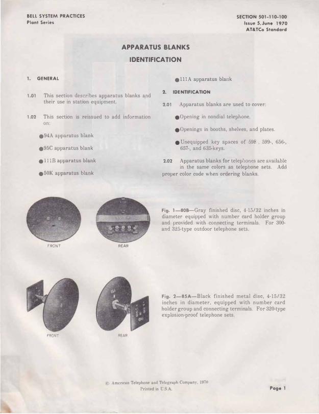
Fig. 1-808-Gray finished disc, 4-15/32 inches in diameter equipped with number card holder group and provided with connecting terminals. For 300-and 325-type outdoor telephone sets.
Fig. 2-85A-Black finished metal disc, 4-15/32 inches in diameter, equipped with number card holder group and connecting terminals. For 320-type explosion-proof telephone sets.
c Am<•rican Telephone and Telegroph Company, 1971l
Printed in U.S.A. Page 1
SECTION 501-110-100
FRONT
Page 2
REAR
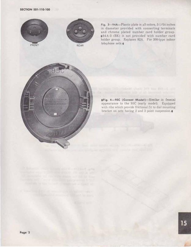
Fig. 3-94A-Piastic plate in all colors, 3-1/54 inches in diameter provided with connecting terminals and chrome plated number card holder group. •94A-3 (BK) i not provided with number card holder group. Replaces 82A. For 300-type indoor telephone sets .•
•Fig. 4-95C (Current Modei)-Similar in frontnl appearance to the 95C (early model). Equipped with ribs which provide frictional fit to dial mounting bracket on sets having 2 and 3 point suspension .•
ISS 5, SECTION 501-110-100
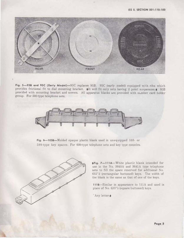
Fig. 5-958 and 95C (Early Modei)-95C replaces 95B. 95C (early model) equipped with ribs which provides frictional fit to dial mounting bracket. •It will fit only sets having 2 point suspension.t 95B provided with mounting bracket and screws. All apparatus blanks are provided with m .. mber card holder group. For 500-type telephone sets.
Fig. 6-1058-Molded opaque plastic blank used in unequipped 598- or
599-type key spaces. For 600-type telephone sets and key type consoles.
•Fig. 7-111A-White plastic blank intended for use in the No. 3640A and 3641A type telephone sets to fill the space reserved for additional No. 635*2 (rectangular buttoned) keys. The width of the blank is the same as that of one of the keys.
1118-Similar in appearance to lllA and used in place of No. 635*5 (square buttoned) keys.
*Any letter.t
Page 3
SECTION 501-110-100
Page 4
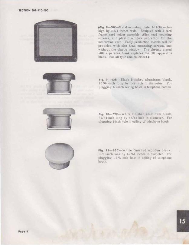
tFig. 8-SOK-Metal mounting plate, 4-11/16 inches high by 4-3/4 inches wide. Equipped with a card frame, card holder assembly, Allen head mounting screws, and plastic window protector for the instruction card. Early production models will be provided with slot head mounting screws, and without the plastic window. The chrome plated 50K apparatus blank replaces the 501 apparatus blank. For all type coin collectors .•
Fig. 9-428 -Black finished aluminum blank, 45/64-inch long by 112-inch in diameter. For plugging 1/2-inch wiring holes in telephone booths.
Fig. 10-72C-White finished aluminum blank, 51/64-inch long by 63/64-inch in diameter. For plug�ing l-inch hole in ceiling of telephone booth.
Fig. 11- 93 C- White finished wo oden blank, 13116-inch long by 1-7/64 inches in diameter. For plugging 1-1/ inch hole in ceiling of telephone booth.
ISS 5, SECTION 501-110-100
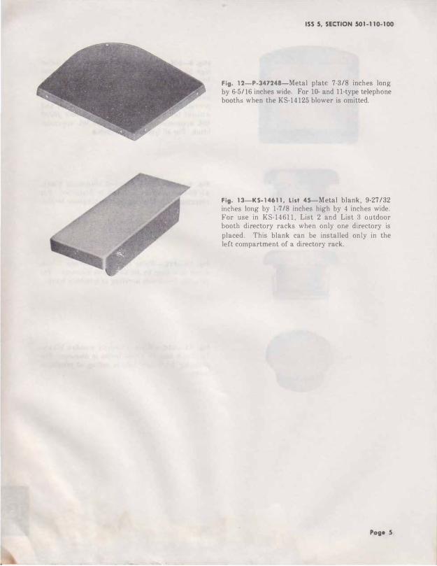
Fig. 12-P-347248-Metal plate 7-3/8 inches long
by 6-5/16 inches wide. For 10- and 11-type telephone booth� when the KS-14125 blower is omitted.
Fig. 13-KS-14611, List 45-Metal blank, 9-27/32 inches long by 1-7/8 inches high by 4 inches wide. For use in KS-14611, List 2 and List 3 outdoor booth directory racks when only one directory is
placed. This blank can be installed only in the left compartment of a directory rack.
Page 5
SECTION 501-110-100
Page 6 6 Pas••
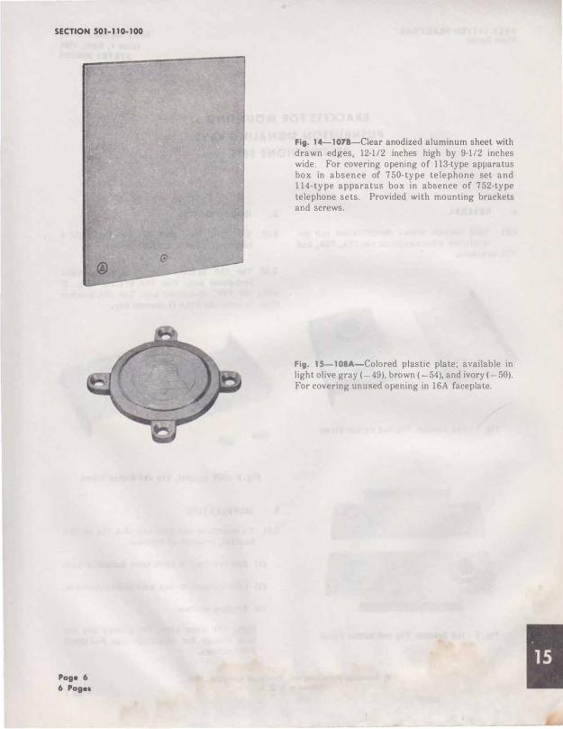
Fig. 14-1078-Ciear anodized aluminum sheet with drawn edges, 12·112 inches high by 9·112 inches wide. For covering opening of 113-type apparatus box in absence of 750-type telephone set and 114-type apparatus box in absence of 752-type telephone sets. Provided with mounting brackets and screws.
Fig. 15-108A-Colored plastic plate; available in light olive gray ( 49), brown (-54), and ivory (-50). For covering unused opening in 16A faceplate.
Recommended