RAD 354 Chapt. 23 Multi-slice CT
• In short – CT is a thin band (fan) of radiation directed toward the pt. and the remnant radiation emitted from the pt. is measured by a receptor and the response transmitted to a computer for reconstruction of the image(s)
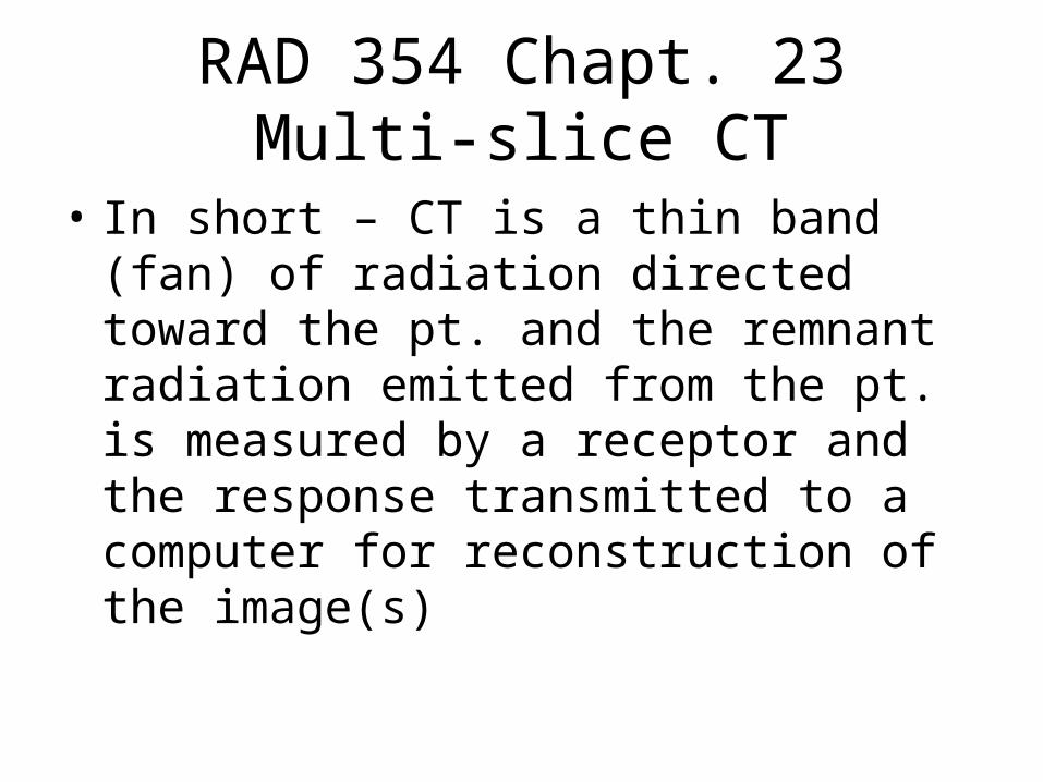
“Slip rings”
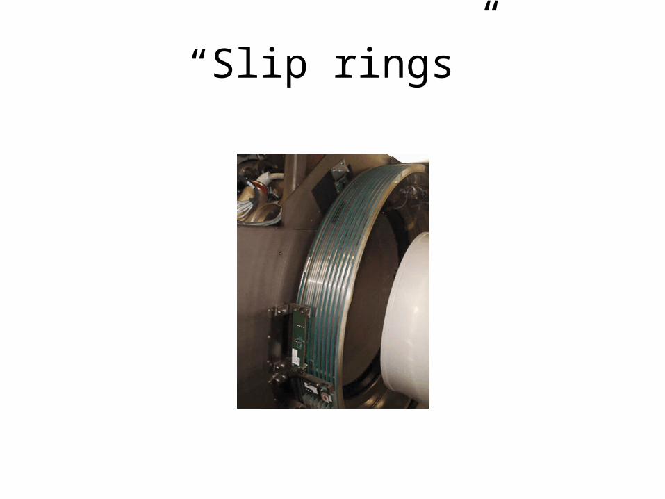
Dates/Activities to Remember
• 1970 – Sir Godfrey Hounsfield,Ph.D.., demonstrated the technique of CT scanning – “EMI” head unit
Dates/Activities Con’t.
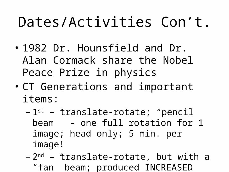
• 1982 Dr. Hounsfield and Dr. Alan Cormack share the Nobel Peace Prize in physics
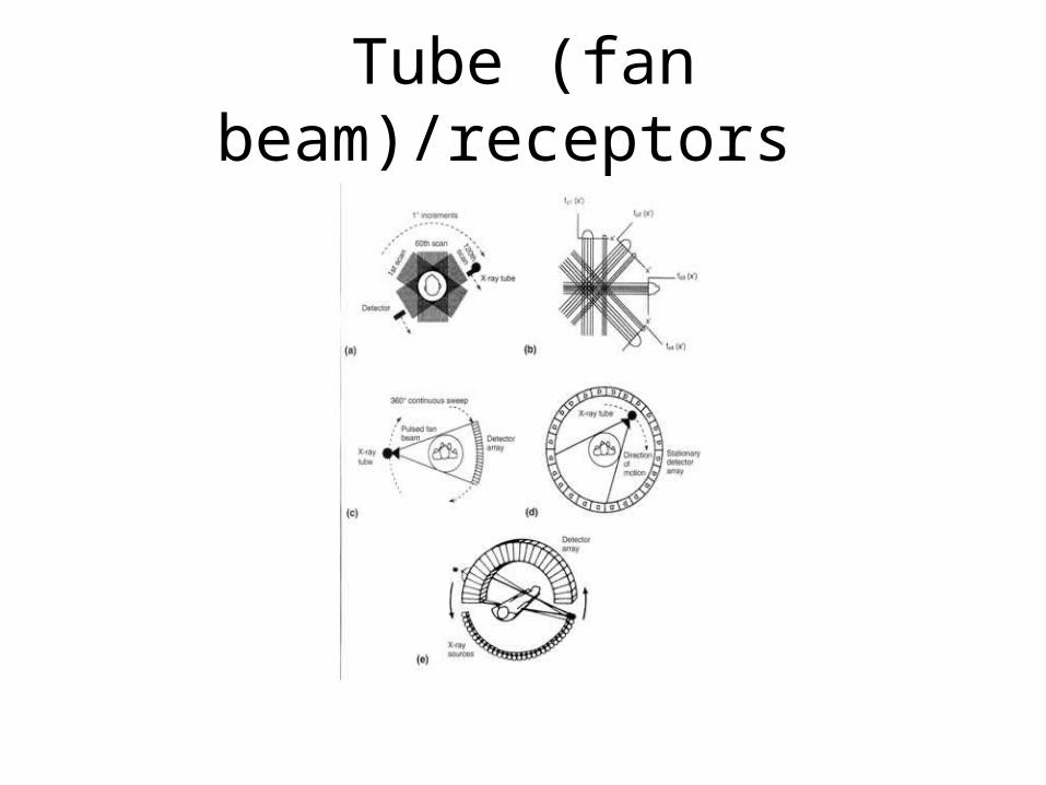
• CT Generations and important items:– 1st – translate-rotate; “pencil beam” - one full
rotation for 1 image; head only; 5 min. per image!– 2nd – translate-rotate, but with a “fan” beam;
produced INCREASED INTENSITY at the edge of the beam – “bow-tie” filter used to remedy this; 30 sec. image time
Generations con’t.
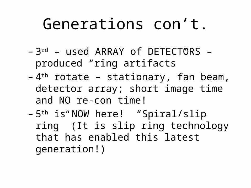
– 3rd – used ARRAY of DETECTORS – produced “ring artifacts”
– 4th rotate – stationary, fan beam, detector array; short image time and NO re-con time!
– 5th is NOW here! “Spiral/slip ring” (It is slip ring technology that has enabled this latest generation!)
Major Components of CT
• Gantry – tube-receptor array, collimators (pre-pt. and pre-detector), generator, pt. couch
• Computer – microprocessor – recon time was a BIG issue until recently
• Operating console – usually two monitors – one for RIS/HIS and the second for the imaging portion (often times a “remote” monitor is set up at the radiologist’s desk – can really be a hassle)
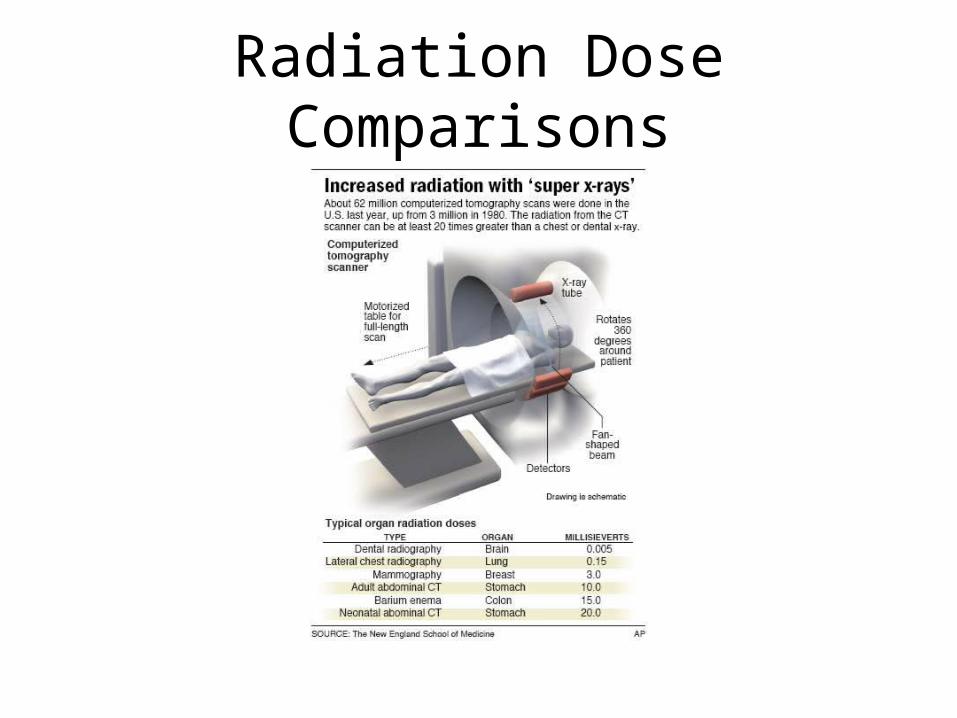
Radiation Dose Comparisons
Current – 5th Generation Terms
• Spiral• Helical• 16/32/64 slice• Slip Rings CT
Interpolation/Extrapolation
• Interpolation – information ALONG the axis WITHIN established values
• Extrapolation – information OUTSIDE axis values established, BUT an ESTIMATED value based upon previously measured parameters IF they continue
“Spiral” Terms
• Pitch – relationship between couch movement and x-ray beam collimation (pitch ratio)– Increasing pitch ratio enables much MORE of the pt. to be
imaged in ONE BREATH HOLD! Breath holds = misrepresentation of the images.
• Slip ring technology made “spiral CT” possible• Three slip rings in the gantry (usually)
– One for hi voltage power to the tube and hi voltage generator– Low voltage power to the rotating gantry portion– Transfer of digital data from gantry receptors to the computer
Multi Slice CT
• Multi detector arrays– Two at once with one beam = two slices per 360
degrees– With “spiral” enables two detectors to produce 16
slices• Envision a person on the table/couch in a
screw/nut fashion going through the gantry
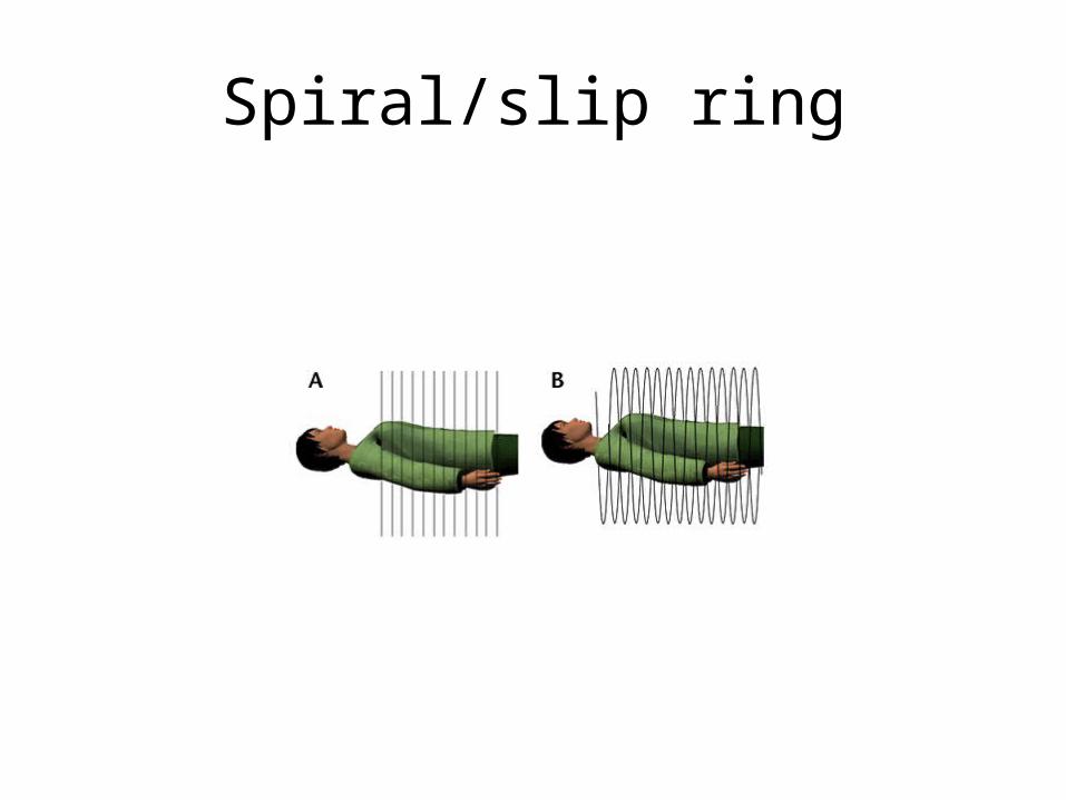
Spiral/slip ring
Tube (fan beam)/receptors
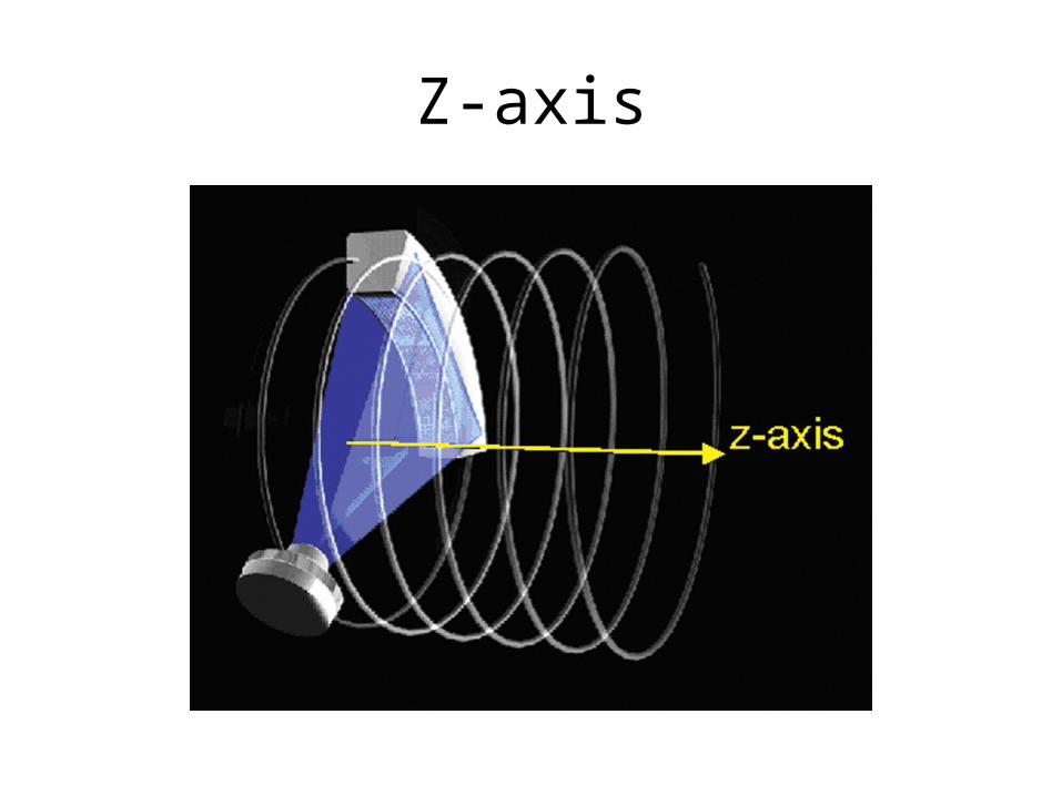
Z-axis
Maximum Intensity Projection (MIP)
• Pre selecting pixel levels to be viewed AFTER obtaining a “rubic’s cube of information”– Then only exhibit those at the PRE-DETERMINED
value – like an MRA or CTA
Spiral Advantages of Conventional CT
• Motion blur is reduced – fewer artifacts• Lowered imaging time (fewer breath holds
required = less motion and less mis-representation)
• Larger volumes can be imaged with LESS part overlap artifacts
Recommended