X2 X1 Z2 E+ E- 0V 110 220 380Z1
R449
R449 revision f
AVRsInstallation and maintenance

2018.01 / gElectric Power Generation
2
Installation and maintenance
R449 revision fAVRs
3983 en -
SAFETY MEASURES
Before using your machine for the first time, it is important to read the whole of this installation and maintenance manual.
All necessary operations and interventions on this machine must be performed by a qualified technician.
Our technical support service will be pleased to provide any additional information you may require.
The various operations described in this manual are accompanied by recom-mendations or symbols to alert the user to potential risks of accidents. It is vital that you understand and take notice of the following warning symbols.
Warning symbol for an operation capable of damaging or destroying the machine or surrounding equipment.
Warning symbol for general danger to personnel.
Warning symbol for electrical danger to personnel.
All servicing or repair operations performed on the AVR should be undertaken by personnel trained in the commissioning, servicing and main-tenance of electrical and mechanical components.
When the generator is driven at a frequency below 28 Hz for more than 30 seconds with an analogue AVR, its AC power supply must be disconnected.
WARNINGThis AVR can be incorporated in a EC-marked machine.This manual is to be given to the end user.
© - We reserve the right to modify the characteristics of this product at any time in order to incorporate the latest technological developments. The information contained in this document may therefore be changed without notice.
This document may not be reproduced in any form without prior authorisation.All brands and models have been registered and patents applied for.
WARNING
This manual concerns the alternator AVR which you have just purchased.We wish to draw your attention to the contents of this maintenance manual.

2018.01 / gElectric Power Generation
3
Installation and maintenance
R449 revision fAVRs
3983 en -
CONTENTS
1 - INTRODUCTION TO THE R449 .........................................................................................41.1 - Application ....................................................................................................................41.2 - Description ...................................................................................................................41.3 - Electrical characteristics ...............................................................................................81.4 - Environment ............................................................................................................... 11
2 - R726: REGULATION OF POWER FACTOR (2F) AND MAINS SENSING (3F) ...............122.1 - Operating diagram .....................................................................................................122.2 - Potentiometers ...........................................................................................................13
3 - TYPICAL DIAGRAMS ......................................................................................................143.1 - AREP 1F LV excitation ...............................................................................................143.2 - AREP 1F MV excitation ..............................................................................................153.3 - AREP 3F LV excitation ...............................................................................................163.4 - AREP 3F MV excitation ..............................................................................................173.5 - 1F LV shunt + booster excitation ................................................................................183.6 - 1F LV PMG excitation .................................................................................................19
4 - COMMISSIONING ............................................................................................................204.1 - In case of standalone regulation .................................................................................204.2 - In case of 1F regulation (parallel operation between alternators) ...............................204.3 - In case of 2F (power factor regulation) and 3F (voltage match circuit) ........................20
5 - TROUBLESHOOTING .....................................................................................................225.1 - Checking the windings and rotating diodes using a separate excitation .....................225.2 - Static checking of the regulator ..................................................................................225.3 - Troubleshooting table ................................................................................................235.4 - Replacing the regulator with a spare voltage regulator ..............................................25
6 - SPARE PARTS .................................................................................................................256.1 - Designation ................................................................................................................256.2 - Technical support service ...........................................................................................25
Disposal and recycling instructions

2018.01 / gElectric Power Generation
4
Installation and maintenance
R449 revision fAVRs
3983 en -
1 - INTRODUCTION TO THE R4491.1 - Application The R449 voltage regulator is of a shunt type. It is designed to fit as standard on A50 to A54 alternators. It can be supplied with power either by a power VT, or by the AREP field excitation system, or by a single-phase or 3-phase PMG. Using the R726 external module, the regulator can control the power factor (2F) and can match the alternator voltage to the mains voltage (3F) prior to synchronisation.
1.2 - Description The electronic components mounted in a plastic casing are sealed with opaque elastomer. Connection is via 2 connectors (male «Faston» lugs 6.3).
The regulator includes: - a main terminal strip (10 terminals) ......J1- a secondary terminal block(5 terminals) ..........................................J2
- a frequency selection terminal block(3 terminals) ..........................................J3
- a quadrature droop potentiometer....... P1- a voltage potentiometer ...................... P2- a stability potentiometer ..................... P3- a maximum excitation potentiometer .. P5- a sensing selection jumper (single/3-phase with an external module) ...... ST1
- a response time jumper .................... ST2- a frequency selection jumper ............ ST3- an external voltage setting jumper .... ST4- a LAM (load adjustment module)jumper ............................................... ST5From R449 Version E number 10,000, this jumper will be removable.
- a selection jumper 13% 25% LAM... ST10- bend at 65 Hz (U/F) ......................... ST11
Two fuses (F1 and F2) are connected to this regulator; they are mounted in the alternator on terminal block C.Type: gG 10/38 16A 500V.- ATQ20 (10x38US) 500 VAC UL/CSA
Simplified diagram of a potentiometer: to adjust the potentiometer, check the actual position of the potentiometer stop.
50
10
Stop

2018.01 / gElectric Power Generation
5
Installation and maintenance
R449 revision fAVRs
3983 en -
1.2.1 - Power supply connection 1.2.1.1 - AREP system
4 x holes Ø 5.8 x 175 x 115 mm
200
mm
140 mm
X2 X1 Z2 E+ E- 0V 110 220 380Z1
AREP SYSTEM
Field
Armature
T1 T2 T3
T4 T5 T6Va
risto
r
5+ 6-
T7 T8 T9
T10 T11 T12
R449
Aux. windings
10 Yellow11 Red
9 Green12 Black
STATOR : 6 or 12-wire (marking T1 to T12)MAIN FIELD
ST5with LAM without LAM
P5 Excitationceiling
ST11
ST2 ST1
knee-point: 65 Hz open
Responsetime
normalfast
P3 Stability
P2TensionSingle-phase
detectionR731 Option
3-ph. detection
External potentiometerfor adjusting the voltage
ST4 Option
T.I.
Option S1 S2
according to tension
Quaddroop
ST350Hz 60Hz
ST1013 % LAM 25 %
P1
Frequency

2018.01 / gElectric Power Generation
6
Installation and maintenance
R449 revision fAVRs
3983 en -
1.2.1.2 - PMG system
4 x holes Ø 5.8 x 175 x 115 mm
200
mm
140 mm
X2 X1 Z2 E+ E- 0V 110 220 380Z1
T1 T2 T3
T4 T5 T6Va
risto
r
5+ 6-
T7 T8 T9
T10 T11 T12
R449
ST5
P5
ST11
ST2 ST1
P3
P2Tension R731
ST4 Option
T.I.
Option S1 S2
14 15 16
PMG
PMG SYSTEM
Field
Armature
Aux. windings
STATOR : 6 or 12-wire (marking T1 to T12)MAIN FIELD
with LAM without LAM
Excitationceiling
knee-point: 65 Hz open
Responsetime
normalfast
StabilitySingle-phase
detectionOption
3-ph. detection
External potentiometerfor adjusting the voltage
according to tension
Quaddroop
ST350Hz 60Hz
ST1013 % LAM 25 %
P1
Frequency

2018.01 / gElectric Power Generation
7
Installation and maintenance
R449 revision fAVRs
3983 en -
1.2.1.3 - SHUNT system
4 x trous Ø 5.8 x 175 x 115 mm
200
mm
140 mm
X2 X1 Z2 E+ E- 0V 110 220 380Z1
T1 T2 T3
T4 T5 T6
Varis
tor
5+ 6-
T7 T8T9
T10 T11 T12
R449
ST5
P5
ST11
ST2 ST1
P3
P2Tension R731
ST4 Option
T.I.
Option S1 S2
SHUNT SYSTEM
Field
Armature
STATOR : 6 or 12-wire (marking T1 to T12)MAIN FIELD
with LAM without LAM
Excitationceiling
knee-point: 65 Hz open
Responsetime
normalfast
StabilitySingle-phase
detectionOption
3-ph. detection
External potentiometerfor adjusting the voltage
according to tension
Quaddroop
ST350Hz 60Hz
ST1013 % LAM 25 %
P1
Frequency

2018.01 / gElectric Power Generation
8
Installation and maintenance
R449 revision fAVRs
3983 en -
1.3 - Electrical characteristics 1.3.1 - Operating diagram
DET
ECTI
ON
SEN
SIN
G
TEN
SIO
NVO
LTAG
E
STA
BIL
ITE
STA
BIL
ITY
STAT
ISM
EVO
LTAG
E D
ROO
P
POTE
NTI
OM
ETR
E TE
NSI
ON
EXTE
RIE
UR
EXTE
RN
AL
VOLT
AGE
POTE
NTI
OM
ETR
E
BO
RN
IER
CO
NN
ECTO
R J
1
SOU
S-VI
TESS
EU
ND
ERFR
EQU
ENC
Y
LIM
ITE
D'E
XCIT
ATIO
NEX
CIT
ATIO
N L
IMIT
TEM
PSTI
ME
RES
ISTA
NC
ER
ESIS
TOR
EXC
ITAT
EUR
EXC
ITER
TRA
NSI
STO
RD
E PU
ISSA
NC
EPO
WER
TR
AN
SIST
OR
LAM
ST5
V/H
z
% L
AM
ST1
065
Hz
ST11
BO
RN
IER
CO
NN
ECTO
R J
2
BO
RN
IER
CO
NN
ECTO
R J
3
380V 1
DC
ST1
P3ST2
PID
AC
2 3 4 5 4220V
110V 0V
S2 TI/C
TS1
ST4
3 Ph
60H
z50
Hz
ST3
+15V
P5
P1
3 2 1
1
1 11
23
6
7Z2 Z1 X2 X19 10 8
5

2018.01 / gElectric Power Generation
9
Installation and maintenance
R449 revision fAVRs
3983 en -
1.3.2 - Detection The detection is single-phase and is isolated using an internal transformer.Sensing VA: 5VAJ1 connector, input voltages:- Terminals 0-110V: voltage range from 85 to 130V- Terminals 0-220V: voltage range from 170 to 260V- Terminals 0-380V: voltage range from 340 to 520V
1.3.3 - Voltage accuracy The voltage accuracy is +/- 0.5 %Un, steady state, linear load.
1.3.4 - Voltage adjustmentThe voltage is adjusted either using an internal potentiometer P2, with a voltage range of +/- 10%Un, or using an external potentiometer (as an option).The voltage is minimum when internal potentiometer P2 has been rotated fully anti-clockwise.
P2
Connecting the external potentiometer: - External potentiometer 470Ω 3W: voltage range +/- 5%Un- External potentiometer 1kΩ 3W: voltage range +/- 10%UnRemove jumper ST4 and connect the external potentiometer as shown in the diagram below. If a regulator is built into the terminal box, remove jumper ST10 from terminal block C and connect the external potentiometer.
J2
ST4
J2
ST4Rhe
Internal External
Voltage setting : ST4A.F. = Internal
1.3.5 - Power supply The power can be supplied:
- using 2 independent auxiliary windings integrated in the alternator stator (AREP excitation),- using a single or 3-phase power VT,- using a single or 3-phase PMG.The single or 3-phase voltage must not exceed 240V AC.
1.3.6 - Output power The output power is 7A 63V under normal conditions and 15A for 10s under overload conditions.
1.3.7 - Quadrature droop (1F) Quadrature droop is achieved using a parallel operation CT (In/1A, 10VA Cl1).The voltage droop can be adjusted using potentiometer P1. The voltage range is 5%Un for Pn PF 0.8.The quadrature droop is at 0 when potentiometer P1 has been rotated fully anti-clockwise.
P1
1.3.8 - Frequency compared with voltage (without LAM)
100 %
50 Hz 60 Hz Hz
50 Hz
48 Hz57.5 Hz
60 Hz
Voltage Bend
U/UN
Frequency
1.3.9 - LAM (Load Acceptance Module) characteristicsThe LAM system is integrated in the regulator, as standard it is active (ST5 with bridge). It can be deactivated by removing the ST5 bridge. It can be adjusted to 13% or 25% by means of the ST10 jumper (factory setting 15%).- Role of the “LAM” (Load Acceptance Module):On application of a load, the rotation speed of the generator set decreases. When it passes below the preset frequency threshold, the LAM causes the voltage to drop by approximately 13% or 25% and
2018.01 / gElectric Power Generation
10
Installation and maintenance
R449 revision fAVRs
3983 en -
consequently the amount of active load applied is reduced by approximately 25% to 45%, until the speed reaches its rated value again.Hence the LAM can be used either to reduce the speed variation (frequency) and its duration for a given applied load, or to increase the applied load possible for one speed variation (turbo-charged engine).To avoid voltage oscillations, the trip threshold for the LAM function should be set approximately 2 Hz below the lowest frequency in steady state. It is advisable to use the LAM at 25% for load impacts ≥ 70% of the genset rated power.
LAM
UN
048 or 57.5 Hz
0.87 UN
Voltage
U/f
50 or 60 Hz
fC fN
VoltageST5 disconnected
ST3
P2
Underspeed and LAM
1.3.10 - Typical effects of the LAM with a diesel engine with or without a LAM (U/F only) 1.3.10.1 - Voltage
UN
0
0,9
0,8
(U/f)withLAM Time
without LAM
1 s 2 s 3 s
Transient voltage drop
1.3.10.2 - Frequency
0.9
0.8
fNMax speed drop
0
withLAM
Time
withoutLAM
1 s 2 s 3 s
1.3.10.3 - Power
0 1 s 2 s 3 sTime
LAM
Variation in the load
Load
on
the
shaf
t (kW
)
Load shedding due to "LAM"
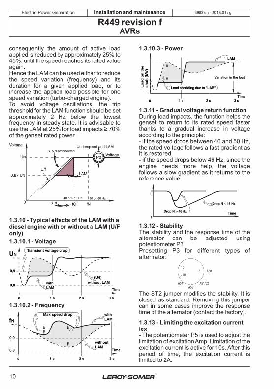
1.3.11 - Gradual voltage return function During load impacts, the function helps the genset to return to its rated speed faster thanks to a gradual increase in voltage according to the principle:- if the speed drops between 46 and 50 Hz, the rated voltage follows a fast gradient as it is restored.- if the speed drops below 46 Hz, since the engine needs more help, the voltage follows a slow gradient as it returns to the reference value.
0Time
Drop N ≤ 46 Hz
U
Drop N > 46 Hz
1.3.12 - Stability The stability and the response time of the alternator can be adjusted using potentiometer P3.Presetting P3 for different types of alternator:
5 A50
A53
0
10
A54 A51/52
The ST2 jumper modifies the stability. It is closed as standard. Removing this jumper can in some cases improve the response time of the alternator (contact the factory).
1.3.13 - Limiting the excitation current iex - The potentiometer P5 is used to adjust the limitation of excitation Amp. Limitation of the excitation current is active for 10s. After this period of time, the excitation current is limited to 2A.

2018.01 / gElectric Power Generation
11
Installation and maintenance
R449 revision fAVRs
3983 en -
The maximum limitation is 15A.The minimum limitation is when the potentiometer has been rotated fully anti-clockwise.In the absence of specification to the contrary, P5 is positioned at the clockwise limit.- Static adjustment of the maximum excitation current.For this value, the static adjustment is possible when the alternator is stopped, which will not endanger the alternator or the installation.Disconnect the power supply wires X1,X2 and Z1,Z2 and the alternator voltage reference (terminal strip J1).Connect the power supply, 200 to 240V, as shown (X1 and X2: 0-220V). Install a 20 ADC ammeter in series with the exciter field.Turn P5 fully anti-clockwise, switch on the power supply (circuit breaker A).If the regulator does not discharge, turn potentiometer P2 (voltage) clockwise until the ammeter indicates a stabilised current.Switch the power supply off and then on again, turn P5 clockwise until the required excitation current is reached (limited to 15A), (for precise adjustment contact the factory). Checking the internal protection:Open the circuit breaker (D): the excitation current must rise to its preset upper limit, maintain this value for 10s and fall back automatically to a value less than 1A.To reset, switch off the power supply using the circuit breaker (A). Note: After setting the upper excitation limit using this procedure, re-adjust the voltage.
Exciter field ~ 10 ohms
R449X2Z1X1Z2E+E-0V
220V380V
P2
P3
P5
50Hz 60Hz
S1 S2
ST1
ST2
P1
ST3
ST5
Mains (Supply 50/60 Hz)
20A DC
ST4
Excit max
Voltage
A+-
According to frequency
A
D
1.3.14 - Protection There are two fuses in the power section. They are mounted externally to the AVR but
inside the alternator terminal box. Rating: gG 10/38 16A 500V- ATQ20 (10x38US) 500 VAC UL/CSA
1.3.15 - Voltage build-up The voltage build-up is automatic (no overvoltage) from the residual magnetism.If there is no voltage build-up, a short pulse of continuous isolated voltage (12VDC), will usually remedy this. Otherwise, proceed in accordance with the diagram below to re-establish the residual magnetism:
R449 X2Z1X1Z2E+E-
J1 +-
t
(12V - 10A)
Exciter field
Isolated DCpower supply
~ 10 ohms
1.3.16 - Power used The power used by the R449 is 30W, when the alternator is at rated power.
1.3.17 - De-energising The regulator is de-energised by switching off the voltage regulation power supply.Contact rating: 15A, 250V AC
R449
X2Z1X1Z2E+E-
Aux. windingsJ1
1.4 - Environment- Operating temperature: - 30°C to +70°C- Storage temperature: - 55°C to + 85°C- Shocks on the base: 9g for the 3 right-angled directions- Vibrations: Less than 10Hz: 2mm half peak amplitude 10Hz to 100Hz: 100mm/sAbove 100Hz: 8g

2018.01 / gElectric Power Generation
12
Installation and maintenance
R449 revision fAVRs
3983 en -
2 - R726: REGULATION OF POWER FACTOR (2F) AND MAINS SENSING (3F)The power factor and mains sensing are done by the R726 module. See the specific manual.
2.1 - Operating diagram

2018.01 / gElectric Power Generation
13
Installation and maintenance
R449 revision fAVRs
3983 en -
2.2 - PotentiometersP1: Potentiometer for adjusting the alternator voltage to the mains voltage (operating mode 3F) P2: Adjustment of the power factorP3: StabilityP4: Limitation of the power factor
10987654321
400
0
S1S2
}}
T3
T2
T1
1 2 3 4 5 6 7 8 9 10
LED
P3
P4
P1
ST1 ST2
MAINS VOLTAGE(PHASES 2-3)
GENERATOR VOLTAGE(PHASES 2-3)
RED
GREEN
"U = U"
"Cos ϕ"
}}
J1
P5 C1 C2 P6
UVOLTAGE U = U "Cos ϕ" "Cos ϕ"
J2
TI / CT / 1A (PHASE 1)LIMIT
To A.V.R.
P1
P2
P3
P4
P5 : (-R) =
P6 : (+R) =
MORE GEN VOLTAGE
MORE REACTIVE POWER
STABILITY (// with mains)
P.F. LAG Limit
MORE VOLTAGE (single)
MORE REACTIVE POWER
U = U100 mm
115
mm
SEN
SIN
G 5
0/60
Hz
POTENTIOMETERS
+
+ADJUSTMENTS / MONITORING
CONTROL OUTPUT
P2Cos ϕ
STAB
R2 R1
Unused terminal
400100
100
0 }R726

2018.01 / gElectric Power Generation
14
Installation and maintenance
R449 revision fAVRs
3983 en -
3 - TYPICAL DIAGRAMSThe following diagrams are supplied for information only and are not to be used in place of the actual alternator diagrams.
3.1 - AREP 1F LV excitation

2018.01 / gElectric Power Generation
15
Installation and maintenance
R449 revision fAVRs
3983 en -
3.2 - AREP 1F MV excitation

2018.01 / gElectric Power Generation
16
Installation and maintenance
R449 revision fAVRs
3983 en -
3.3 - AREP 3F LV excitation

2018.01 / gElectric Power Generation
17
Installation and maintenance
R449 revision fAVRs
3983 en -
3.4 - AREP 3F MV excitation

2018.01 / gElectric Power Generation
18
Installation and maintenance
R449 revision fAVRs
3983 en -
3.5 - 1F LV Shunt + Booster excitation

2018.01 / gElectric Power Generation
19
Installation and maintenance
R449 revision fAVRs
3983 en -
3.6 - 1F LV PMG excitation

2018.01 / gElectric Power Generation
20
Installation and maintenance
R449 revision fAVRs
3983 en -
4 - COMMISSIONINGThe commissioning principle is the same whatever is the type of excitation.4.1 - In case of standalone regulation - Check fuses F1 and F2 which are situated on terminal block C in the alternator.- Check the regulator:- Check the position of the ST3 jumper (select the frequency, 50 or 60Hz).- If an external voltage potentiometer is used, disconnect it from the regulator and install the ST4 jumper (regulator terminal block J2) or the ST10 jumper, terminal block C in the alternator terminal box.- Turn the internal voltage potentiometer P2 on the regulator fully anti-clockwise.- Set the alternator to its rated speed using the drive system.- The alternator voltage should rise to a value of 85 to 90%Un.- Adjust the voltage to the required value using potentiometer P2.- Turn potentiometer P1 fully anti-clockwise.- Perform an on-load test with power factor = 0.8 or power factor = 1. The voltage should remain constant within the limits of the regulator. If it is not stable, see section 1.3.9.- Stop the alternator and reconnect the external potentiometer, setting it to the centre position.- Set the alternator to its rated speed then, using the external potentiometer, set the alternator to its rated voltage.- The regulator set-up phase is now complete.
4.2 - In case of 1f regulation (parallel operation between alternators) - The previous settings should be made on each alternator.- Set the quadrature droop potentiometer to the centre position and perform an on-load test.- With a load at power factor = 1, the voltage does not drop or only drops slightly; with an inductive load, the voltage drops. This voltage drop is set using quadrature droop potentiometer P1. The no-load voltage is
always greater than the on-load voltage, if the voltage rises, invert the parallel operation CT. The voltage quadrature droop is generally 2 to 3% of the rated voltage.- The no-load voltages should be identical on all the alternators intended for parallel operation between each other.- Connect the alternators in parallel at no load.- Adjust the setting of voltage P2 or the external voltage potentiometer of one of the machines, try to eliminate (or minimise) the circulating stator current between the machines.- Do not adjust the voltage further.- Match the kW power with a minimum load of 30% by adjusting the drive system speed.- Adjust quadrature droop potentiometer P1 on one of the machines to balance or distribute the stator currents.- If several alternators are in parallel, take one as a reference.
4.3 - In case of 2f (power factor regulation) and 3f (voltage match circuit) (see R726 manual ref. 2440)- Check the wiring between the R449 and the R726. (See the connection diagram).- Check the information given for the R726: mains voltage, 2F contact, 3F contact.- If an external voltage potentiometer is used, disconnect it from the R726 and add the ST1 jumper (terminals 3 and 4 of J1) or disconnect it from terminals 25 and 26 of terminal block C of the alternator and add the ST10 jumper.- If an external PF potentiometer is used, disconnect it from the R726 and add the ST2 jumper (terminals 9 and 10 of J1) or disconnect it from terminals 29 and 30 of terminal block C of the alternator and add the ST11 jumper.- Perform a 1F test.The test principle is the same as in the case of 1F regulation.- Matching the alternator and mains voltages prior to synchronisation (3F):- If this function is not used, match the voltages by adjusting the voltage potentiometer.

2018.01 / gElectric Power Generation
21
Installation and maintenance
R449 revision fAVRs
3983 en -
The following settings are for the R726.Close the 3F contact (terminals 5 and 6 of J1 of the R726 or terminals 34 and 35 of terminal block C of the alternator). The red LED lights up. Adjust potentiometer P1 to match the alternator voltage to the mains voltage.- Power factor regulation with the alternator synchronised with the mains (2F):The following settings are for the R726.When the alternator is in phase with the mains and the mains and alternator voltages are equal, proceed with synchronisation. Contact 2F closes when the circuit breaker is closed. The green LED on the R726 lights up. Open contact 3F and remove the mains voltage reference.Preset the PF potentiometer P2 to 5 and limit potentiometer P4 to 3.5.Without supplying kW power to the mains, the reactive current of the alternator should be at or around 0.Increase the kW power. When it reaches 50% of the rated power, adjust potentiometer P4 to obtain a PF of 0.9 LAG (inductive) on the alternator. The range is then 0.7 LAG PF (inductive) (P2 turned fully clockwise) to 0.95 LEADING (capacitive) (P2 turned fully anti-clockwise).Adjust P2 to obtain the required power factor value.Increase the kW power until it reaches the rated power. The PF should remain constant.If it becomes unstable, adjust potentiometer P3 on the R726 or potentiometer P3 on the R449.- Stop the alternator and reconnect the external potentiometers.

2018.01 / gElectric Power Generation
22
Installation and maintenance
R449 revision fAVRs
3983 en -
5 - TROUBLESHOOTING5.1 - Checking the windings and rotating diodes using a separate excitation During this procedure, you must check that the alternator is not connected to any external loads and examine the terminal box to check that the connections have been made correctly.- Stop the generator, disconnect and isolate the regulator wires.- There are two possible assemblies for a separate excitation: see the diagrams below.- Assembly A: Connect the DC supply (2 batteries in series) in series with a rheostat of approximately 20 ohms/500W and a diode on both field winding wires (5+) (6-).
6 - 5 +
Diode 5 A
Battery 12V
Rh. 20 - 500 W
-+
ASSEMBLY A
Exciter field
- Assembly B: Connect a «variac» variable power supply and a diode bridge to both field winding wires (5+) (6-).- These two systems must be compatible with the excitation rating of the machine (see the nameplate).- Run the generator set at its nominal speed.- Gradually increase the power supply current of the field winding by adjusting the rheostat or variac and measure output voltages L1, L2, L3, checking the no-load excitation voltages and currents. (See the alternator nameplate or ask factory for the test log).- If the output voltages are at their rated values and are balanced at < 1% for the given excitation value, the machine is operating correctly and the fault is due to the regulation part (regulator, wiring, sensing, auxiliary windings).
When the alternator is stopped, mains voltage may still be present at the module voltage sensing terminals.
Do not perform dielectric tests without disconnecting the module and associated AVR.
RISK OF DESTRUCTION
-
+
6 - 5 + Variac
AC220 V
Diode5A
50 60
7080
90
100
40
3020
10
0
ASSEMBLY B
Exciter field
5.2 - Static checking of the regulatorIf the regulator operates correctly during a static test, this does not necessarily mean that it will operate correctly under real conditions.If the regulator fails the static test, it can be concluded without doubt that the regulator is faulty.Connect a test bulb in accordance with the diagram.The power supply voltage must be between 200 and 240V. The voltage of the bulb is 230V. The power of the bulb will be less than 100W.- Turn potentiometer P2 fully anti-clockwise.- Switch the regulator on; the bulb must briefly light up and then go out.- Slowly turn the voltage potentiometer clockwise, to the right.- When turned fully clockwise, the bulb lights up continuously.- At the regulation point, turning the voltage adjustment potentiometer slightly in one direction or the other should make the bulb light up or go out. If the bulb is either lit continuously or does not light up at all, the regulator is faulty.

2018.01 / gElectric Power Generation
23
Installation and maintenance
R449 revision fAVRs
3983 en -
- Perform one test supplying the regulator via terminals X1 and X2, then another supplying it via terminals Z1 and Z2.
According to frequency 200 - 240 V(220 V) R449
X2Z1X1Z2E+E-0V
220V380V
P2
P3
P5
50Hz 60Hz
S1 S2
ST1
ST2
P1
ST3
ST5 Mains(Supply50/60 Hz)
V 300 V :D C
ST4
Voltage
5.3 - Troubleshooting tableBefore taking any action on the R449 or the R726, pay careful attention to the positions of the potentiometers and the jumpers.
5.3.1 - In case of 1F, parallel operation between alternators Symptom Probable causes Solutions
Absence of voltage on start-up, at no load
- No residual magnetism or polarity inversion between the excitation output and the exciter input
- De-energising contacts open- The speed is less than the rated speed- Connection lost between the regulator and the exciter
- Alternator loaded or short-circuited- External potentiometer connected incorrectly- Faulty regulator- Faulty exciter or rotating diode bridge- Fuses blown
- Voltage built-up is required
- Close this contact- Adjust the speed.- Check the wiring
- Remove the load from the alternator- Check the wiring- Test it or change it- Check the exciter and the diodes- Replace the fuses
Voltage too high and adjustment potentiometer not operating
- Incorrect voltage at the sensing terminals
- Loss of sensing- The external potentiometer has an incorrect value
- Faulty regulator
- Check the wiring of the 0, 110V, 220V, 380V terminals on terminal block J1
- Check the wiring- Set a potentiometer with the correct value
- Test it or change it
Voltage too high, but adjustable by the adjustment potentiometer
- Voltage potentiometer set too high
- Regulator sensing incorrect
- Regulator faulty
- Adjust voltage potentiometer P2 or the external potentiometer
- Check the wiring and the sensing value, at 0V and 110V, 220V, 380V terminals
- Test it or change it
Voltage too low, but adjustable by the adjustment potentiometer
- ST3 and ST4 jumpers
- The speed is too low- Exciter and rotating diodes
- Check the presence of the ST3 and ST4 jumpers
- Set to the correct speed- Check the exciter and the rotating diodes
Incorrectregulation
- Distortion of the waveform, non-linear load- Unbalanced load
- The speed is not at the correct value- Exciter or rotating diodes faulty- Faulty regulator
- Contact the factory- Balance the load or change the sensing points
- Adjust the speed- Check the exciter and the rotating diodes- Test it or change it

2018.01 / gElectric Power Generation
24
Installation and maintenance
R449 revision fAVRs
3983 en -
Symptom Probable causes Solutions
Voltage unstable
- Frequency unstable
- Secondary sensing of a transformer supplying other devices
- Stability potentiometer P3 is incorrectly set- Faulty regulator
- Check the stability of the drive system speed
- Provide separate sensing for the alternator
- Adjust stability potentiometer P3- Test it or change it
Response time too long
- Stability adjustment
- Speed regulator response too long
- Adjust stability potentiometer P3 and the ST2 jumper
- Adjust the stability of the speed
Considerable drop in voltage, on-load
- Vectorial composition fault between the voltage and the current
- The parallel operation CT ratio is incorrect
- Check the wiring of the sensing and parallel operation CT
- Correct the CT ratio
kVAR not stable between alternators (reactive current circulation)
- Quadrature droop potentiometer needs adjusting
- The no-load voltages are not identical
- Phases not connected to the sensing correctly
- The CT is not on the correct phase
- Adjust the quadrature droop potentiometer
- Check that all the alternators have the same no-load voltage value
- Check the sensing wiring
- Check the position of the parallel operation CT
Warning : after operational testing, replace all access panels or covers.
5.3.2 - Example of 2F and 3F Symptom Probable causes Solutions
Incorrect regulation of PF, PF potentiometer not operating
- Vectorial composition fault between the sensing voltage and the stator current
- R726 faulty- R726 ST2 jumper missing- Wiring fault between the R449 and the R726
- Check the sensing wiring and the parallel operation CT
- Change the module- Check the wiring, in particular the wires between 1 and 2 of terminal block J1 on the R726
PF range incorrect. - Settings on potentiometers P2 incorrect - Reset the range as shown above
The LEDs will not light up - Contacts 2F and 3F missing - Check the wiring
Cannot adjust the voltage matching circuit
- The sensing voltage is incorrect or incorrectly connected
- Check the wiring and the value of the voltage
Warning : after operational testing, replace all access panels or covers.

2018.01 / gElectric Power Generation
25
Installation and maintenance
R449 revision fAVRs
3983 en -
5.3.3 - Checking the alternator using a separate excitation- The alternator is tested at no load.- Disconnect the R449 and R726 and the entire excitation system of the alternator.- Connect a 24V 5A variable DC supply to the exciter field wires.Apply a direct current to the exciter to obtain the rated voltage.- Check all the alternator parameters: stator voltage, field winding voltage, AREP or regulator power transformer voltages, sensing voltage at the regulator terminal block.- All these parameters should be checked against the alternator characteristics.
5.4 - Replacing the regulator with a spare voltage regulatorSet the potentiometers and the jumpers in the same way as the original regulator.
6 - SPARE PARTS6.1 - DesignationDescription Type Code
AVR R449 AEM 220 RE 030
6.2 - Technical support serviceOur technical support service will be pleased to provide any additional information you may require.
For all spare parts orders or technical support requests, send your request to [email protected] or your closest contact, whom you will find at www.lrsm.co/support indicating the type and the code number of the AVR.
To ensure that our products operate correctly and safely, we recommend the use of original manufacturer spare parts.
In the event of failure to comply with this advice, the manufacturer cannot be held responsible for any damage.

2018.01 / gElectric Power Generation
26
Installation and maintenance
R449 revision fAVRs
3983 en -
Disposal and recycling instructionsWe are committed limiting the environmental impact of our activity. We continuously monitor our production processes, material sourcing and products design to improve recyclability and minimise our environmental footprint.
These instructions are for information purposes only. It is the user’s responsibility to comply with local legislation regarding product disposal and recycling.
Waste & hazardous materials The following components and materials require special treatment and must be separated from the alternator before the recycling process:- electronic materials found in the terminal box, including the automatic voltage regulator (198), current transformers (176), interference suppression module (199) and other semi-conductors.- diode bridge (343) and surge suppressor (347), found on the alternator rotor.- major plastic components, such as the terminal box structure on some products. These components are usually marked with information concerning the type of plastic.

[email protected] www.lrsm.co/support
Design
Life Extension
Optimisation
Start-up
Operation
•Consulting & specification•Maintenance
contracts
•Reconditioning•System upgrade
•Monitoring•System audit
•Commissioning•Training
•Genuine spare parts•Repair services
Our worldwide service network of over 80 facilities is at your service.This local presence is our guarantee for fast and efficient repair, support and maintenance services.Trust your alternator maintenance and support to electric power generation experts. Our field personnel are 100% qualified and fully trained to operate in all environments and on all machine types.We have a deep understanding of alternator operation, providing the best value service to optimise your cost of ownership.
Where we can help:
Contact us:Americas: +1 (507) 625 4011Europe & Rest of the world: +33 238 609 908Asia Pacific: +65 6250 8488 China: +86 591 88373036India: +91 806 726 4867Middle East: +971 4 811 8483 Scan the code or go to:
Service & Support

- 2018.01 / g
www.leroy-somer.com/epg
3983 en
Linkedin.com/company/Leroy-SomerTwitter.com/Leroy_Somer_enFacebook.com/LeroySomer.Nidec.enYouTube.com/LeroySomerOfficiel
Recommended