Copyright © The Boeing Company. See title page for details.
D6-27370-804-BRI(P2)
Quick Action Index
QA.Index.1
737 Flight Crew Operations Manual
Aborted Engine Start ......................... 7.1
Airspeed Unreliable ......................... 10.1
APU FIRE........................................... 8.1
AUTOMATIC UNLOCK <> ................... 1.1
CABIN ALTITUDE WARNING... 2.1
Emergency Descent < >..........0.1ENGINE FIRE ..................................... 8.2
Engine Limit or Surge or Stall............ 7.2
ENGINE OVERHEAT............................ 8.4
Engine Severe Damage or Separation 8.2
Engine Tailpipe Fire........................... 8.6
Evacuation <> ........ Back Cover.2LANDING CONFIGURATION ............. 15.1
Loss Of Thrust On Both Engines ........ 7.4
Overspeed ....................................... 15.1
Rapid Depressurization .......... 2.1Runaway Stabilizer <>...................... 9.1
Smoke, Fire or Fumes .............8.8TAKEOFF CONFIGURATION.............. 15.1
WARNING HORN (INTERMITTENT).. 15.2
WARNING LIGHT - CABIN ALTITUDE OR TAKEOFF CONFIGURATION ............ 15.2
July 17, 2009
Quick Action Index
737Quick Reference Handbook
737 Flight Crew Operations Manual
Quick Reference Handbook -Quick Action Index
Copyright © The Boeing Company. See title page for details.
D6-27370-804-BRI(P2)QA.Index.2
IntentionallyBlank
July 17, 2009
Copyright © The Boeing Company. See title page for details.
D6-27370-804-BRI(P2)
737 Flight Crew Operations Manual
Lights Chapter LightsIndex Section Index
Lights.Index.1
AA/P ................................................................4.1A/T ................................................................4.1AFT - Cargo Fire and FIRE WARN......................8.12AFT CARGO .....................................................1.2AFT ENTRY ......................................................1.5AFT SERVICE...................................................1.9ALIGN and FAULT - IRS................................. 11.10ALIGN and FAULT - IRS...................................11.6ALT ALERT ....................................................15.3ALT DISAGREE...............................................10.2ALTN - EEC .....................................................7.9ANTISKID INOP .............................................14.1AOA DISAGREE..............................................10.2APU - Fire and FIRE WARN ................................8.1APU DET INOP ...............................................8.10AUTO BRAKE DISARM.....................................14.4AUTO FAIL ......................................................2.2AUTO SLAT FAIL ..............................................9.5AUTO UNLK .....................................................1.1AUX PITOT ......................................................3.2
BBAT DISCHARGE ..............................................6.1BLEED TRIP OFF...............................................2.5
CCABIN ALTITUDE..............................................2.1CAPT PITOT.....................................................3.2CDS FAULT....................................................10.3CONFIG (Airplanes with Center Tank
Auto Shutoff) .............................................12.1CONFIG (Airplanes without Center Tank
Auto Shutoff) .............................................12.1COWL ANTI-ICE ...............................................3.1COWL VALVE OPEN - Engine Anti-ice ..................3.1
July 17, 2009
Lights Index
737 Flight Crew Operations Manual
Copyright © The Boeing Company. See title page for details.
D6-27370-804-BRI(P2)
Lights.Index.2
Lights.Index.2
DDC FAIL ........................................................11.4DETECTOR FAULT...........................................8.13DISPLAYS CONTROL PANEL .............................10.4DRIVE............................................................ 6.1DSPLY SOURCE..............................................10.4DUAL BLEED................................................... 2.6
EELEC ............................................................. 6.1ELT ............................................................... 1.4ENG 1 OVERHEAT............................................ 8.4ENG 2 OVERHEAT............................................ 8.4ENG FAIL (both).............................................. 7.4ENG FAIL (single)...........................................7.10Engine 1 - Fire and FIRE WARN ......................... 8.2Engine 2 - Fire and FIRE WARN ......................... 8.2ENGINE CONTROL ..........................................7.10EQUIP............................................................ 1.6
FF/O PITOT ...................................................... 3.2FAULT - APU................................................... 7.8FAULT - Engine Fire/Overheat Detector .............8.14FAULT - IRS ................................................11.10FAULT - IRS ..................................................11.6FAULT and ALIGN - IRS.................................11.10FAULT and ALIGN - IRS...................................11.6FEEL DIFF PRESS ............................................ 9.5FILTER BYPASS..............................................12.7FIRE WARN and AFT - Cargo Fire......................8.12FIRE WARN and APU - Fire ............................... 8.1FIRE WARN and Engine 1 - Fire ......................... 8.2FIRE WARN and Engine 2 - Fire ......................... 8.2FIRE WARN and FWD - Cargo Fire.....................8.12FIRE WARN and WHEEL WELL - Fire..................8.18FLAP LOAD RELIEF .......................................... 9.5FMC - CDU Alerting.........................................11.3FMC - FMC DISAGREE .....................................11.1
July 17, 2009
737 Flight Crew Operations Manual Lights.Index.3
Copyright © The Boeing Company. See title page for details.
D6-27370-804-BRI(P2) Lights.Index.3
FMC - FMC FAIL (With Dual FMC Option) ...........11.2FMC and MSG - CDU Alerting ...........................11.3FMC and MSG - FMC DISAGREE........................11.1FMC DISAGREE..............................................11.1FWD - Cargo Fire and FIRE WARN ....................8.12FWD CARGO....................................................1.2FWD ENTRY.....................................................1.5FWD SERVICE..................................................1.9
GGEN OFF BUS, SOURCE OFF and TRANSFER BUS OFF
(both sides) .................................................6.2GLS..............................................................11.3GPS..............................................................11.4
IIAS DISAGREE...............................................10.5ILS...............................................................11.4IMBAL ........................................................ 12.10INOP - Ground Proximity.................................15.3
LL ALPHA VANE .................................................3.2L ELEV PITOT ..................................................3.2L VALVE OPEN - Wing Anti-ice............................3.4LE FLAPS TRANSIT ...........................................9.9LEFT AFT OVERWING........................................1.8LEFT FWD OVERWING.......................................1.8LOCK FAIL.......................................................1.8LOW OIL PRESSURE - APU.................................7.8LOW OIL PRESSURE - Engine...........................7.15LOW PRESSURE - Flight Control .........................9.5LOW PRESSURE - Fuel Pump ...........................12.8LOW PRESSURE - Hydraulic Pump - Standby.... 13.13LOW PRESSURE - Hydraulic Pump -
System A (both) .........................................13.2LOW PRESSURE - Hydraulic Pump -
System A and B..........................................13.8LOW PRESSURE - Hydraulic Pump -
System B (both) .........................................13.4LOW PRESSURE - Hydraulic Pump (single).........13.1
July 17, 2009
737 Flight Crew Operations Manual
Copyright © The Boeing Company. See title page for details.
D6-27370-804-BRI(P2)
Lights.Index.4
Lights.Index.4
LOW QUANTITY............................................13.13LOW...........................................................12.11
MMACH TRIM FAIL ............................................9.11MSG and FMC - CDU Alerting ...........................11.3MSG and FMC - FMC DISAGREE........................11.1
NNO AUTOLAND................................................ 4.1NO LAND 3..................................................... 4.1NOT ARMED ................................................... 1.4
OOFF - Equipment Cooling.................................. 2.6OFF - Flight Recorder ......................................10.5OFF - Window Heat.......................................... 3.2OFF SCHED DESCENT ...................................... 2.7OIL FILTER BYPASS ........................................7.16ON DC ........................................................11.12OVER SPEED - APU.......................................... 7.9OVERHEAT - Hydraulic Pump ...........................13.1OVERHEAT - Window ....................................... 3.3
PPACK ............................................................. 2.8PASS OXY ON ................................................. 1.8PSEU ............................................................15.4
RR ALPHA VANE................................................ 3.2R ELEV PITOT ................................................. 3.2R VALVE OPEN - Wing Anti-ice .......................... 3.4REV..............................................................7.24REVERSER.....................................................7.23RIGHT AFT OVERWING..................................... 1.8RIGHT FWD OVERWING ................................... 1.8
SSOURCE OFF (both)......................................... 6.2SOURCE OFF (single) ....................................... 6.6
July 17, 2009
737 Flight Crew Operations Manual Lights.Index.5
Copyright © The Boeing Company. See title page for details.
D6-27370-804-BRI(P2) Lights.Index.5
SOURCE OFF, TRANSFER BUS OFF and GEN OFF BUS (both sides) .................................................6.2
SPEED BRAKE DO NOT ARM - Without Load Alleviation System......................................................9.12
SPEED TRIM FAIL ...........................................9.12SPEEDBRAKES EXTENDED...............................9.13STAB OUT OF TRIM ........................................9.14STANDBY PWR OFF ..........................................6.7START VALVE OPEN........................................7.25STBY RUD ON................................................9.17
TTAI ................................................................3.1TAKEOFF CONFIG...........................................15.1TEMP PROBE ...................................................3.2TR UNIT..........................................................6.7TRANSFER BUS OFF..........................................6.8TRANSFER BUS OFF, SOURCE OFF and GEN OFF (both
sides)..........................................................6.2
UUNABLE REQD NAV PERF - RNP (FMC Update U10.7
and Later)................................................ 11.13
VVALVE OPEN - Crossfeed .................................12.2
WWHEEL WELL - Fire and FIRE WARN..................8.18WING-BODY OVERHEAT ..................................2.10
YYAW DAMPER ................................................9.29
ZZONE TEMP ...................................................2.13
July 17, 2009
737 Flight Crew Operations Manual
Copyright © The Boeing Company. See title page for details.
D6-27370-804-BRI(P2)
Lights.Index.6
Lights.Index.6
IntentionallyBlank
July 17, 2009
Copyright © The Boeing Company. See title page for details.
D6-27370-804-BRI(P2)
737 Flight Crew Operations Manual
Unannunciated Chapter UnannIndex Section Index
Unann.Index.1
Aborted Engine Start.....................................7.1ACARS Electrical Power Loss ..............................5.1ACARS MU Fail or DU Fail ..................................5.1Airspeed Unreliable.....................................10.1All Flaps Up Landing <>....................................9.3Bomb Threat <>..............................................0.2Brake Pressure Indicator Zero PSI ....................14.5Display Failure ...............................................10.3Ditching <> ....................................................0.7
Emergency Descent < >.................0.1Engine Failure or Shutdown .............................7.10Engine Fuel Leak............................................12.4Engine High Oil Temperature ...........................7.12Engine In-Flight Start .....................................7.13Engine Limit or Surge or Stall .......................7.2Engine Severe Damage or Separation ...........8.2Engine Tailpipe Fire ......................................8.6
Evacuation <> ............... Back Cover.2Fuel Quantity Indication Inoperative .................12.9Fuel Temperature Low ....................................12.9High Engine Vibration .....................................7.17Hijack <> .....................................................0.10Jammed or Restricted Flight Controls <>.............9.6Landing Gear Lever Jammed in the Up
Position <>................................................14.6Landing Gear Lever Will Not Move Up After
Takeoff <> ................................................14.9Loss Of Thrust On Both Engines ....................7.4Manual Gear Extension ................................. 14.12One Engine Inoperative Landing <> .................7.18One Engine Inoperative Landing <> .................7.20Overspeed...................................................15.1Partial or All Gear Up Landing <>................... 14.14Pilot Incapacitation <> ...................................0.11Radio Transmit Continuous (Stuck
Microphone Switch).......................................5.1
July 17, 2009
Unannunciated Index
737 Flight Crew Operations Manual
Copyright © The Boeing Company. See title page for details.
D6-27370-804-BRI(P2)
Unann.Index.2
Unann.Index.2
Rapid Depressurization ................ 2.1Runaway Stabilizer <>..................................9.1Smoke or Fumes Removal ...............................8.16
Smoke, Fire or Fumes.................... 8.8Stabilizer Trim Inoperative <> .........................9.15Tailstrike On Takeoff.......................................15.5Trailing Edge Flap Asymmetry <> ....................9.18Trailing Edge Flap Disagree <> ........................9.21Trailing Edge Flaps Up Landing <> ...................9.26Unscheduled Pressurization Change <>.............. 2.2Volcanic Ash ..................................................7.26Window Damage ............................................1.10Window Open ................................................1.12
July 17, 2009
Copyright © The Boeing Company. See title page for details.
D6-27370-804-BRI(P2)
737 Flight Crew Operations Manual
Alphabetical Chapter AlphaIndex Section Index
Alpha.Index.1
AA/P ................................................................4.1A/T ................................................................4.1Aborted Engine Start.....................................7.1ACARS Electrical Power Loss ..............................5.1ACARS MU Fail or DU Fail ..................................5.1AFT - Cargo Fire and FIRE WARN......................8.12AFT CARGO .....................................................1.2AFT ENTRY ......................................................1.5AFT SERVICE...................................................1.9Airspeed Unreliable.....................................10.1ALIGN and FAULT - IRS................................. 11.10ALIGN and FAULT - IRS...................................11.6All Flaps Up Landing <>....................................9.3ALT ALERT ....................................................15.3ALT DISAGREE ..............................................10.2ALTITUDE ALERT ...........................................15.3ALTN - EEC .....................................................7.9ANTISKID INOP .............................................14.1ANTISKID INOPERATIVE <> ...........................14.1AOA DISAGREE .............................................10.2APU - Fire and FIRE WARN ................................8.1APU DET INOP ...............................................8.10APU DETECTION INOPERATIVE .......................8.10APU FAULT .....................................................7.8APU FIRE ................................................... 8.1APU LOW OIL PRESSURE ..................................7.8APU OVERSPEED .............................................7.9AUTO BRAKE DISARM <> ...............................14.4AUTO FAIL <>.................................................2.2AUTO SLAT FAIL .............................................9.5AUTO UNLK .....................................................1.1AUTOMATIC UNLOCK <> ............................ 1.1AUTOPILOT DISENGAGE ..................................4.1AUTOTHROTTLE DISENGAGE ............................4.1AUX PITOT ......................................................3.2
July 17, 2009
Alphabetical Index
737 Flight Crew Operations Manual
Copyright © The Boeing Company. See title page for details.
D6-27370-804-BRI(P2)
Alpha.Index.2
Alpha.Index.2
BBAT DISCHARGE ............................................. 6.1BATTERY DISCHARGE ..................................... 6.1BLEED TRIP OFF ............................................. 2.5Bomb Threat <> ............................................. 0.2Brake Pressure Indicator Zero PSI ....................14.5
C
CABIN ALTITUDE WARNING.......... 2.1CABIN ALTITUDE............................................. 2.1CAPT PITOT.................................................... 3.2CARGO DOOR ................................................ 1.2CARGO FIRE < > ...........................................8.12CARGO FIRE DETECTOR FAULT .......................8.13CDS FAULT ...................................................10.3CONFIG < > All aircraft (except G-CDZM with centre
tank fuel pump restrictions in force) .............12.1CONFIG < > G-CDZM (with centre tank fuel pump
restrictions in force) ...................................12.1COWL ANTI-ICE .............................................. 3.1COWL VALVE OPEN - Engine Anti-ice.................. 3.1CROSSFEED SELECTOR INOPERATIVE ..............12.2
DDC FAIL ........................................................11.4DETECTOR FAULT...........................................8.13Display Failure ...............................................10.3DISPLAY SOURCE ..........................................10.4DISPLAYS CONTROL PANEL ............................10.4Ditching <>.................................................... 0.7DRIVE ........................................................... 6.1DSPLY SOURCE..............................................10.4DUAL BLEED .................................................. 2.6
EEEC ALTERNATE MODE .................................... 7.9ELEC ............................................................ 6.1ELT .............................................................. 1.4
Emergency Descent < > ................ 0.1EMERGENCY EXIT LIGHTS NOT ARMED ............. 1.4
July 17, 2009
737 Flight Crew Operations Manual Alpha.Index.3
Copyright © The Boeing Company. See title page for details.
D6-27370-804-BRI(P2) Alpha.Index.3
ENG 1 OVERHEAT.............................................8.4ENG 2 OVERHEAT.............................................8.4ENG FAIL (both) ..............................................7.4ENG FAIL (single)...........................................7.10Engine 1 - Fire and FIRE WARN..........................8.2Engine 2 - Fire and FIRE WARN..........................8.2ENGINE CONTROL .........................................7.10ENGINE COWL ANTI-ICE ..................................3.1ENGINE COWL VALVE OPEN OR TAI INDICATION .3.1Engine Failure or Shutdown .............................7.10ENGINE FIRE.................................................8.2ENGINE FIRE/OVERHEAT DETECTOR FAULT ......8.14Engine Fuel Leak............................................12.4Engine High Oil Temperature ...........................7.12Engine In-Flight Start .....................................7.13Engine Limit or Surge or Stall .......................7.2ENGINE LOW OIL PRESSURE ..........................7.15ENGINE OIL FILTER BYPASS ...........................7.16ENGINE OVERHEAT .................................... 8.4Engine Severe Damage or Separation ...........8.2Engine Tailpipe Fire ......................................8.6ENTRY DOOR ..................................................1.5EQUIP ............................................................1.6EQUIPMENT COOLING OFF ...............................2.6EQUIPMENT DOOR ..........................................1.6
Evacuation <> ............... Back Cover.2
FF/O PITOT.......................................................3.2FAULT - APU....................................................7.8FAULT - Engine Fire/Overheat Detector .............8.14FAULT - IRS ................................................ 11.10FAULT - IRS ..................................................11.6FAULT and ALIGN - IRS................................. 11.10FAULT and ALIGN - IRS...................................11.6FEEL DIFF PRESS .............................................9.5FEEL DIFFERENTIAL PRESSURE .........................9.5FILTER BYPASS..............................................12.7FIRE WARN and AFT - Cargo Fire......................8.12
July 17, 2009
737 Flight Crew Operations Manual
Copyright © The Boeing Company. See title page for details.
D6-27370-804-BRI(P2)
Alpha.Index.4
Alpha.Index.4
FIRE WARN and APU - Fire ............................... 8.1FIRE WARN and Engine 1 - Fire ......................... 8.2FIRE WARN and Engine 2 - Fire ......................... 8.2FIRE WARN and FWD - Cargo Fire.....................8.12FIRE WARN and WHEEL WELL - Fire..................8.18FLAP LOAD RELIEF ......................................... 9.5FLIGHT CONTROL LOW PRESSURE .................... 9.5FLIGHT RECORDER OFF ..................................10.5FMC - CDU Alerting.........................................11.3FMC - FMC DISAGREE .....................................11.1FMC - FMC FAIL (With Dual FMC Option)............11.2FMC and MSG - CDU Alerting ...........................11.3FMC and MSG - FMC DISAGREE........................11.1FMC DISAGREE .............................................11.1FMC FAIL .....................................................11.2FMC/CDU ALERTING MESSAGE ........................11.3FUEL FILTER BYPASS .....................................12.7FUEL PUMP LOW PRESSURE ............................12.8Fuel Quantity Indication Inoperative .................12.9Fuel Temperature Low ....................................12.9FWD - Cargo Fire and FIRE WARN.....................8.12FWD CARGO................................................... 1.2FWD ENTRY.................................................... 1.5FWD SERVICE................................................. 1.9
GGEN OFF BUS, SOURCE OFF and TRANSFER BUS OFF
(both sides) ................................................ 6.2GLS .............................................................11.3GPS .............................................................11.4GROUND PROXIMITY INOPERATIVE .................15.3
HHigh Engine Vibration .....................................7.17Hijack <> .....................................................0.10HYDRAULIC PUMP LOW PRESSURE ..................13.1HYDRAULIC PUMP OVERHEAT .........................13.1
IIAS DISAGREE ..............................................10.5
July 17, 2009
737 Flight Crew Operations Manual Alpha.Index.5
Copyright © The Boeing Company. See title page for details.
D6-27370-804-BRI(P2) Alpha.Index.5
ILS ..............................................................11.4IMBAL ....................................................... 12.10INOP - Ground Proximity.................................15.3IRS DC FAIL .................................................11.4IRS FAULT .................................................. 11.10IRS FAULT ....................................................11.6IRS ON DC ................................................. 11.12
JJammed or Restricted Flight Controls <>.............9.6
LL ALPHA VANE .................................................3.2L ELEV PITOT ..................................................3.2L VALVE OPEN - Wing Anti-ice............................3.4LANDING CONFIGURATION ...................... 15.1Landing Gear Lever Jammed in the Up
Position <>................................................14.6Landing Gear Lever Will Not Move Up After
Takeoff <> ................................................14.9LE FLAPS TRANSIT ...........................................9.9LEADING EDGE FLAPS TRANSIT <> ...................9.9LEFT AFT OVERWING........................................1.8LEFT FWD OVERWING.......................................1.8LOCK FAIL ......................................................1.8LOSS OF BOTH ENGINE DRIVEN GENERATORS ....6.2LOSS OF SYSTEM A <> ..................................13.2LOSS OF SYSTEM A AND SYSTEM B <>.............13.8LOSS OF SYSTEM B <> ..................................13.4Loss Of Thrust On Both Engines ....................7.4LOW .......................................................... 12.11LOW OIL PRESSURE - APU.................................7.8LOW OIL PRESSURE - Engine...........................7.15LOW PRESSURE - Flight Control .........................9.5LOW PRESSURE - Fuel Pump ...........................12.8LOW PRESSURE - Hydraulic Pump - Standby.... 13.13LOW PRESSURE - Hydraulic Pump -
System A (both) .........................................13.2LOW PRESSURE - Hydraulic Pump -
System A and B..........................................13.8
July 17, 2009
737 Flight Crew Operations Manual
Copyright © The Boeing Company. See title page for details.
D6-27370-804-BRI(P2)
Alpha.Index.6
Alpha.Index.6
LOW PRESSURE - Hydraulic Pump -System B (both) .........................................13.4
LOW PRESSURE - Hydraulic Pump (single) .........13.1LOW QUANTITY............................................13.13
MMACH TRIM FAIL ...........................................9.11Manual Gear Extension..................................14.12MANUAL REVERSION <>.................................13.8MSG and FMC - CDU Alerting ...........................11.3MSG and FMC - FMC DISAGREE........................11.1
NNO AUTOLAND ............................................... 4.1NO LAND 3 .................................................... 4.1NOT ARMED ................................................... 1.4
OOFF - Equipment Cooling.................................. 2.6OFF - Flight Recorder ......................................10.5OFF - Window Heat.......................................... 3.2OFF SCHED DESCENT ...................................... 2.7OFF SCHEDULE DESCENT ................................ 2.7OIL FILTER BYPASS ........................................7.16ON DC ........................................................11.12One Engine Inoperative Landing <> .................7.18One Engine Inoperative Landing <> .................7.20OVER SPEED - APU.......................................... 7.9OVERHEAT - Hydraulic Pump ...........................13.1OVERHEAT - Window ....................................... 3.3Overspeed...................................................15.1OVERWING DOOR .......................................... 1.8
PPACK ............................................................ 2.8Partial or All Gear Up Landing <>...................14.14PASS OXY ON ................................................. 1.8PASSENGER OXYGEN ON ................................. 1.8Pilot Incapacitation <> ...................................0.11PROBE HEAT .................................................. 3.2PSEU ...........................................................15.4
July 17, 2009
737 Flight Crew Operations Manual Alpha.Index.7
Copyright © The Boeing Company. See title page for details.
D6-27370-804-BRI(P2) Alpha.Index.7
RR ALPHA VANE.................................................3.2R ELEV PITOT ..................................................3.2R VALVE OPEN - Wing Anti-ice ...........................3.4Radio Transmit Continuous (Stuck
Microphone Switch).......................................5.1
Rapid Depressurization ................. 2.1REV..............................................................7.24REVERSER ....................................................7.23REVERSER UNLOCKED (IN FLIGHT) .................7.24RIGHT AFT OVERWING .....................................1.8RIGHT FWD OVERWING ....................................1.8Runaway Stabilizer <> .................................9.1
SSERVICE DOOR ...............................................1.9Smoke or Fumes Removal ...............................8.16
Smoke, Fire or Fumes ....................8.8SOURCE OFF ..................................................6.6SOURCE OFF (both)..........................................6.2SOURCE OFF, TRANSFER BUS OFF and GEN OFF BUS
(both sides) .................................................6.2SPEED BRAKE DO NOT ARM <> ......................9.12SPEED TRIM FAIL ..........................................9.12SPEEDBRAKES EXTENDED ..............................9.13STAB OUT OF TRIM ........................................9.14STABILIZER OUT OF TRIM ..............................9.14Stabilizer Trim Inoperative <>.........................9.15STANDBY HYDRAULIC LOW PRESSURE ........... 13.13STANDBY HYDRAULIC LOW QUANTITY ........... 13.13STANDBY POWER OFF ......................................6.7STANDBY PWR OFF ..........................................6.7STANDBY RUDDER ON ...................................9.17START VALVE OPEN .......................................7.25STBY RUD ON................................................9.17
TTAI ................................................................3.1Tailstrike On Takeoff.......................................15.5
July 17, 2009
737 Flight Crew Operations Manual
Copyright © The Boeing Company. See title page for details.
D6-27370-804-BRI(P2)
Alpha.Index.8
Alpha.Index.8
TAKEOFF CONFIG...........................................15.1TAKEOFF CONFIGURATION ...................... 15.1TEMP PROBE................................................... 3.2TR UNIT ........................................................ 6.7Trailing Edge Flap Asymmetry <> ....................9.18Trailing Edge Flap Disagree <> ........................9.21Trailing Edge Flaps Up Landing <> ...................9.26TRANSFER BUS OFF ........................................ 6.8TRANSFER BUS OFF, SOURCE OFF and GEN OFF (both
sides)......................................................... 6.2
UUNABLE REQD NAV PERF - RNP .....................11.13Unscheduled Pressurization Change <>.............. 2.2
VVALVE OPEN - Crossfeed .................................12.2Volcanic Ash ..................................................7.26
WWARNING HORN (INTERMITTENT) .............15.2WARNING LIGHT - CABIN ALTITUDE OR TAKE-
OFF CONFIGURATION ..............................15.2WHEEL WELL - Fire and FIRE WARN..................8.18WHEEL WELL FIRE .........................................8.18Window Damage ............................................1.10WINDOW HEAT OFF ........................................ 3.2Window Open ................................................1.12WINDOW OVERHEAT ...................................... 3.3WING ANTI-ICE VALVE OPEN ........................... 3.4WING-BODY OVERHEAT .................................2.10
YYAW DAMPER ...............................................9.29
ZZONE TEMP ..................................................2.13
July 17, 2009
737 Flight Crew Operations Manual
Normal Checklists Chapter NC
Copyright © The Boeing Company. See title page for details.
D6-27370-804-BRI(P2) NC.1
NC. Normal Checklists-Table of ContentsNormal Checklists
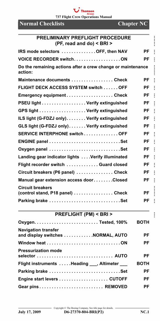
PRELIMINARY PREFLIGHT PROCEDURE (PF, read and do) < BRI >
IRS mode selectors . . . . . . . . . . . . . . OFF, then NAV PFVOICE RECORDER switch. . . . . . . . . . . . . . . . . . . ON PFDo the remaining actions after a crew change or maintenance action:Maintenance documents . . . . . . . . . . . . . . . . . Check PFFLIGHT DECK ACCESS SYSTEM switch . . . . . . OFF PFEmergency equipment . . . . . . . . . . . . . . . . . . . Check PFPSEU light . . . . . . . . . . . . . . . . . . Verify extinguished PFGPS light . . . . . . . . . . . . . . . . . . . Verify extinguished PFILS light (G-FDZJ only). . . . . . . . Verify extinguished PFGLS light (G-FDZJ only) . . . . . . . Verify extinguished PFSERVICE INTERPHONE switch . . . . . . . . . . . . . . OFF PFENGINE panel . . . . . . . . . . . . . . . . . . . . . . . . . . . . .Set PFOxygen panel . . . . . . . . . . . . . . . . . . . . . . . . . . . . .Set PFLanding gear indicator lights . . . .Verify illuminated PFFlight recorder switch . . . . . . . . . . . . . Guard closed PFCircuit breakers (P6 panel) . . . . . . . . . . . . . . . Check PFManual gear extension access door . . . . . . . .Closed PFCircuit breakers (control stand, P18 panel) . . . . . . . . . . . . . . . . Check PFParking brake . . . . . . . . . . . . . . . . . . . . . . . . . . . . .Set PF
PREFLIGHT (PM) < BRI >Oxygen. . . . . . . . . . . . . . . . . . . . . . . . . . Tested, 100% BOTHNavigation transfer and display switches . . . . . . . . . . . .NORMAL, AUTO PFWindow heat . . . . . . . . . . . . . . . . . . . . . . . . . . . . . . ON PFPressurization modeselector . . . . . . . . . . . . . . . . . . . . . . . . . . . . . . . AUTO PFFlight instruments . . . . .Heading ___, Altimeter ___ BOTHParking brake . . . . . . . . . . . . . . . . . . . . . . . . . . . . .Set PFEngine start levers . . . . . . . . . . . . . . . . . . . . CUTOFF PFGear pins . . . . . . . . . . . . . . . . . . . . . . . . . . REMOVED PF
July 17, 2009
::::::::::::::::::::::::::::::::::::::::::::::
::
737 Flight Crew Operations Manual
Normal Checklists
Copyright © The Boeing Company. See title page for details.
NC.2 D6-27370-804-BRI(P2)
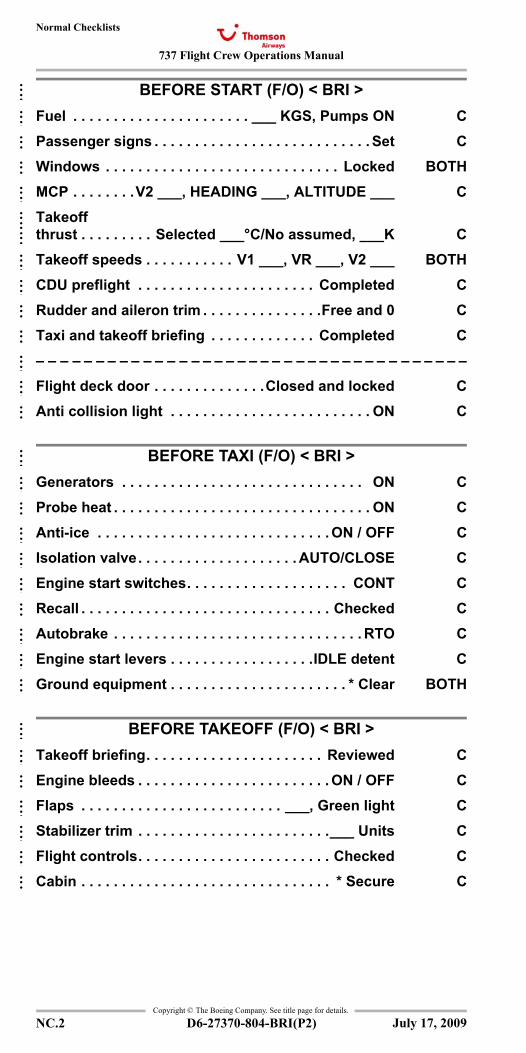
BEFORE START (F/O) < BRI >Fuel . . . . . . . . . . . . . . . . . . . . . . ___ KGS, Pumps ON CPassenger signs . . . . . . . . . . . . . . . . . . . . . . . . . . . Set CWindows . . . . . . . . . . . . . . . . . . . . . . . . . . . . . Locked BOTHMCP . . . . . . . .V2 ___, HEADING ___, ALTITUDE ___ CTakeoffthrust . . . . . . . . . Selected ___°C/No assumed, ___K CTakeoff speeds . . . . . . . . . . . V1 ___, VR ___, V2 ___ BOTHCDU preflight . . . . . . . . . . . . . . . . . . . . . . Completed CRudder and aileron trim . . . . . . . . . . . . . . .Free and 0 CTaxi and takeoff briefing . . . . . . . . . . . . . Completed C– – – – – – – – – – – – – – – – – – – – – – – – – – – – – – – – – – – – –Flight deck door . . . . . . . . . . . . . .Closed and locked CAnti collision light . . . . . . . . . . . . . . . . . . . . . . . . . ON C
BEFORE TAXI (F/O) < BRI >Generators . . . . . . . . . . . . . . . . . . . . . . . . . . . . . . ON CProbe heat . . . . . . . . . . . . . . . . . . . . . . . . . . . . . . . . ON CAnti-ice . . . . . . . . . . . . . . . . . . . . . . . . . . . . . ON / OFF CIsolation valve. . . . . . . . . . . . . . . . . . . . AUTO/CLOSE CEngine start switches. . . . . . . . . . . . . . . . . . . . CONT CRecall . . . . . . . . . . . . . . . . . . . . . . . . . . . . . . . Checked CAutobrake . . . . . . . . . . . . . . . . . . . . . . . . . . . . . . . RTO CEngine start levers . . . . . . . . . . . . . . . . . .IDLE detent CGround equipment . . . . . . . . . . . . . . . . . . . . . . * Clear BOTH
BEFORE TAKEOFF (F/O) < BRI >Takeoff briefing. . . . . . . . . . . . . . . . . . . . . . Reviewed CEngine bleeds . . . . . . . . . . . . . . . . . . . . . . . . ON / OFF CFlaps . . . . . . . . . . . . . . . . . . . . . . . . . ___, Green light CStabilizer trim . . . . . . . . . . . . . . . . . . . . . . . .___ Units CFlight controls. . . . . . . . . . . . . . . . . . . . . . . . Checked CCabin . . . . . . . . . . . . . . . . . . . . . . . . . . . . . . . * Secure C
July 17, 2009
::::::::::::::::::::::::::::
::::::::::::::::::::
::::::::::::::
737 Flight Crew Operations Manual
Normal Checklists
Copyright © The Boeing Company. See title page for details.
D6-27370-804-BRI(P2) NC.3
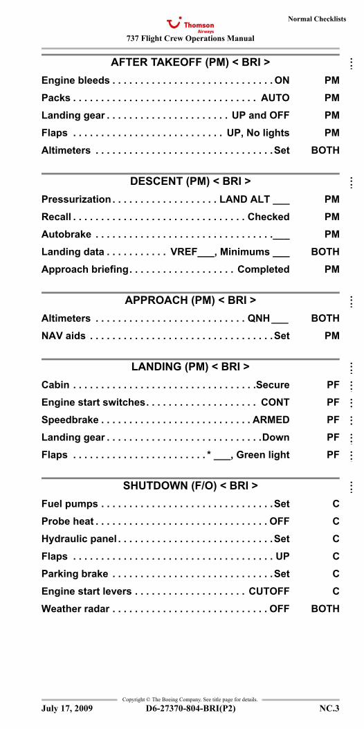
AFTER TAKEOFF (PM) < BRI >Engine bleeds . . . . . . . . . . . . . . . . . . . . . . . . . . . . . ON PMPacks . . . . . . . . . . . . . . . . . . . . . . . . . . . . . . . . . AUTO PMLanding gear . . . . . . . . . . . . . . . . . . . . . . UP and OFF PMFlaps . . . . . . . . . . . . . . . . . . . . . . . . . . . UP, No lights PMAltimeters . . . . . . . . . . . . . . . . . . . . . . . . . . . . . . . .Set BOTH
DESCENT (PM) < BRI >Pressurization . . . . . . . . . . . . . . . . . . . LAND ALT ___ PMRecall . . . . . . . . . . . . . . . . . . . . . . . . . . . . . . . Checked PMAutobrake . . . . . . . . . . . . . . . . . . . . . . . . . . . . . . . .___ PMLanding data . . . . . . . . . . . VREF___, Minimums ___ BOTHApproach briefing. . . . . . . . . . . . . . . . . . . Completed PM
APPROACH (PM) < BRI >Altimeters . . . . . . . . . . . . . . . . . . . . . . . . . . . QNH ___ BOTHNAV aids . . . . . . . . . . . . . . . . . . . . . . . . . . . . . . . . .Set PM
LANDING (PM) < BRI >Cabin . . . . . . . . . . . . . . . . . . . . . . . . . . . . . . . . .Secure PFEngine start switches. . . . . . . . . . . . . . . . . . . . CONT PFSpeedbrake . . . . . . . . . . . . . . . . . . . . . . . . . . . ARMED PFLanding gear . . . . . . . . . . . . . . . . . . . . . . . . . . . .Down PFFlaps . . . . . . . . . . . . . . . . . . . . . . . . * ___, Green light PF
SHUTDOWN (F/O) < BRI >Fuel pumps . . . . . . . . . . . . . . . . . . . . . . . . . . . . . . .Set CProbe heat . . . . . . . . . . . . . . . . . . . . . . . . . . . . . . . OFF CHydraulic panel . . . . . . . . . . . . . . . . . . . . . . . . . . . .Set CFlaps . . . . . . . . . . . . . . . . . . . . . . . . . . . . . . . . . . . . UP CParking brake . . . . . . . . . . . . . . . . . . . . . . . . . . . . .Set CEngine start levers . . . . . . . . . . . . . . . . . . . . CUTOFF CWeather radar . . . . . . . . . . . . . . . . . . . . . . . . . . . . OFF BOTH
July 17, 2009
::
::
::
::::::::::::
::
737 Flight Crew Operations Manual
Normal Checklists
Copyright © The Boeing Company. See title page for details.
NC.4 D6-27370-804-BRI(P2)
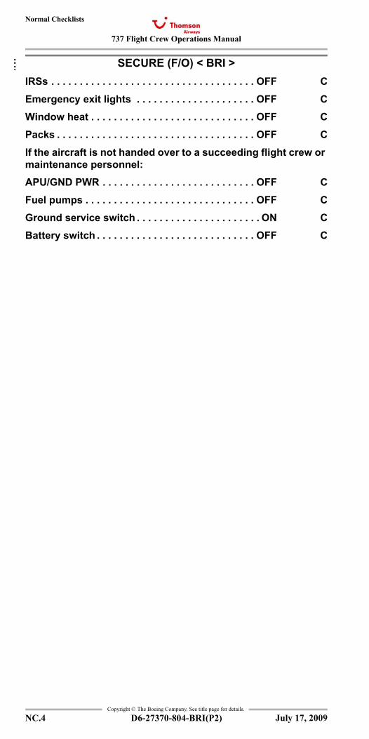
SECURE (F/O) < BRI >IRSs . . . . . . . . . . . . . . . . . . . . . . . . . . . . . . . . . . . . OFF CEmergency exit lights . . . . . . . . . . . . . . . . . . . . . OFF CWindow heat . . . . . . . . . . . . . . . . . . . . . . . . . . . . . OFF CPacks . . . . . . . . . . . . . . . . . . . . . . . . . . . . . . . . . . . OFF CIf the aircraft is not handed over to a succeeding flight crew or maintenance personnel:APU/GND PWR . . . . . . . . . . . . . . . . . . . . . . . . . . . OFF CFuel pumps . . . . . . . . . . . . . . . . . . . . . . . . . . . . . . OFF CGround service switch . . . . . . . . . . . . . . . . . . . . . . ON CBattery switch . . . . . . . . . . . . . . . . . . . . . . . . . . . . OFF C
July 17, 2009
::
737 Flight Crew Operations Manual
Non-Normal Checklists Chapter NNCMiscellaneous Section 0
Table of Contents
Copyright © The Boeing Company. See title page for details.
D6-27370-804-BRI(P2) 0.TOC.1
Emergency Descent < >.................0.1
Bomb Threat <>..............................................0.2Ditching <> ....................................................0.7
Emergency Descent < >.................0.1Hijack <> .....................................................0.10Pilot Incapacitation <> ...................................0.11
July 17, 2009
NNC.0-MiscellaneousTable Of Contents

737 Flight Crew Operations Manual
Non-Normal Checklists -Miscellaneous
Table of Contents
Copyright © The Boeing Company. See title page for details.
D6-27370-804-BRI(P2)0.TOC.2
IntentionallyBlank
July 17, 2009
737 Flight Crew Operations Manual 0.1
Copyright © The Boeing Company. See title page for details.
D6-27370-804-BRI(P2) 0.1
NNC.0 Non-Normal Checklists-Unannunciated Checklists
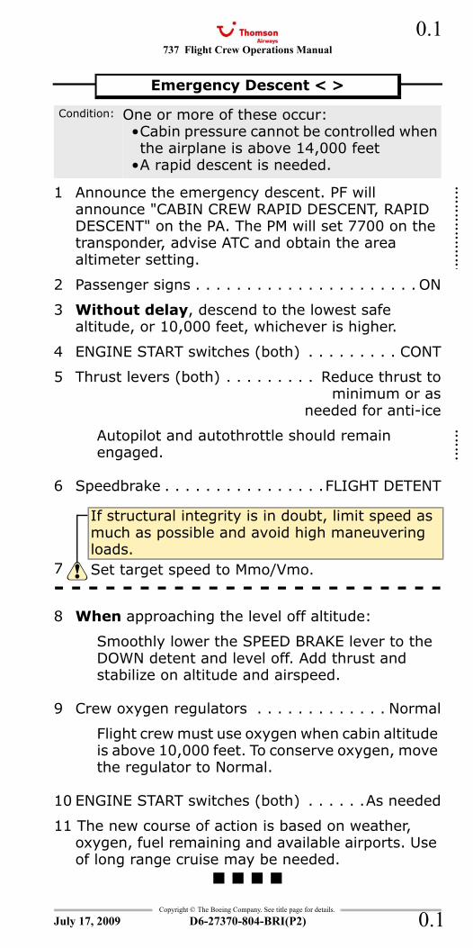
1 Announce the emergency descent. PF will announce "CABIN CREW RAPID DESCENT, RAPID DESCENT" on the PA. The PM will set 7700 on the transponder, advise ATC and obtain the area altimeter setting.
2 Passenger signs . . . . . . . . . . . . . . . . . . . . . . ON
3 Without delay, descend to the lowest safe altitude, or 10,000 feet, whichever is higher.
4 ENGINE START switches (both) . . . . . . . . . CONT
5 Thrust levers (both) . . . . . . . . . Reduce thrust tominimum or as
needed for anti-ice
Autopilot and autothrottle should remain engaged.
6 Speedbrake . . . . . . . . . . . . . . . .FLIGHT DETENT
- - - - - - - - - - - - - - - - - - - - - - -8 When approaching the level off altitude:
Smoothly lower the SPEED BRAKE lever to the DOWN detent and level off. Add thrust and stabilize on altitude and airspeed.
9 Crew oxygen regulators . . . . . . . . . . . . . Normal
Flight crew must use oxygen when cabin altitude is above 10,000 feet. To conserve oxygen, move the regulator to Normal.
10 ENGINE START switches (both) . . . . . .As needed
11 The new course of action is based on weather, oxygen, fuel remaining and available airports. Use of long range cruise may be needed.
Emergency Descent < >
Condition: One or more of these occur:•Cabin pressure cannot be controlled when the airplane is above 14,000 feet
•A rapid descent is needed.
If structural integrity is in doubt, limit speed as much as possible and avoid high maneuvering loads.
7 Set target speed to Mmo/Vmo.
July 17, 2009
::::::::::
::::::::::
::::::::::
::::
::::
::::
737 Flight Crew Operations Manual
Copyright © The Boeing Company. See title page for details.
D6-27370-804-BRI(P2)
0.2
0.2
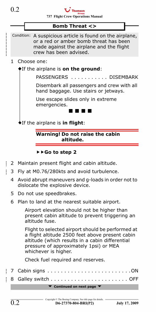
1 Choose one:
2 Maintain present flight and cabin altitude.
3 Fly at M0.76/280kts and avoid turbulence.
4 Avoid abrupt maneuvers and g-loads in order not to dislocate the explosive device.
5 Do not use speedbrakes.
6 Plan to land at the nearest suitable airport.
Airport elevation should not be higher than present cabin altitude to prevent triggering an altitude fuse.
Flight to selected airport should be performed at a flight altitude 2500 feet above present cabin altitude (which results in a cabin differential pressure of approximately 1psi) or MEA whichever is higher.
Check fuel required and reserves.
7 Cabin signs . . . . . . . . . . . . . . . . . . . . . . . . .ON
8 Galley switch . . . . . . . . . . . . . . . . . . . . . . . OFF Continued on next page
Bomb Threat <>
Condition: A suspicious article is found on the airplane, or a red or amber bomb threat has been made against the airplane and the flight crew has been advised.
If the airplane is on the ground:
PASSENGERS . . . . . . . . . . . DISEMBARK
Disembark all passengers and crew with all hand baggage. Use stairs or jetways.
Use escape slides only in extreme emergencies.
If the airplane is in flight:
Warning! Do not raise the cabin altitude.
Go to step 2
July 17, 2009
::::::::
::::::::
::::::::
::::::::::::
::::::::::::
737 Flight Crew Operations Manual 0.3
Copyright © The Boeing Company. See title page for details.
D6-27370-804-BRI(P2) 0.3
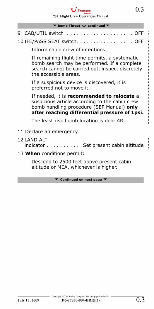
9 CAB/UTIL switch . . . . . . . . . . . . . . . . . . . . OFF
10 IFE/PASS SEAT switch. . . . . . . . . . . . . . . . . OFF
Inform cabin crew of intentions.
If remaining flight time permits, a systematic bomb search may be performed. If a complete search cannot be carried out, inspect discretely the accessible areas.
If a suspicious device is discovered, it is preferred not to move it.
If needed, it is recommended to relocate a suspicious article according to the cabin crew bomb handling procedure (SEP Manual) only after reaching differential pressure of 1psi.
The least risk bomb location is door 4R.
11 Declare an emergency.
12 LAND ALTindicator . . . . . . . . . . . Set present cabin altitude
13 When conditions permit:
Descend to 2500 feet above present cabin altitude or MEA, whichever is higher.
Continued on next page
Bomb Threat <> continued
July 17, 2009
:::::::::::::::::::::::::::::::::
:
:
:::::::::::::::::::::::::::
:
:
:::::::::::::::::::::::::::
:
:
::::
::::
::::
737 Flight Crew Operations Manual
Copyright © The Boeing Company. See title page for details.
D6-27370-804-BRI(P2)
0.4
0.4
14 Captain performs a PA announcement.
Example: "MAY I PLEASE HAVE YOUR ATTENTION. WE HAVE RECEIVED A WARNING THAT A DEVICE HAS BEEN PLACED ON BOARD THIS AIRCRAFT. WE CONSIDER THIS WARNING TO BE A HOAX, AS CALLS OF THIS NATURE HAVE BEEN RECEIVED BY AIRLINES MANY TIMES IN THE PAST. HOWEVER, AS YOUR SAFETY IS OF PARAMOUNT IMPORTANCE, WE MUST TAKE SUCH WARNINGS SERIOUSLY. I AM THEREFORE MAKING ARRANGEMENTS TO LAND AS SOON AS POSSIBLE, SO THAT A THOROUGH SEARCH OF THE AIRCRAFT CAN BE CARRIED OUT."
If applicable: "IN THE MEANTIME, THE CABIN CREW WILL BE CARRYING OUT A SEARCH AND I WOULD BE GRATEFUL FOR YOUR CO-OPERATION. I WOULD LIKE TO REPEAT THAT THIS WARNING IS ALMOST CERTAINLY A HOAX AND THERE IS NO CAUSE FOR ALARM. I WILL LET YOU KNOW AS SOON AS I HAVE ANY FURTHER INFORMATION."
15 After differential pressure zero is reached:
Cabin Crew . . . . . . . . . . . . . . . . . . . . Inform
Pressurization mode selector . . . . . . . . . .MAN
Outflow VALVE switch . . . . . Hold in OPEN untilthe outflow VALVE
indicates fully open
16 Establish the landing configuration early.
The next two actions intend to establish an in-trim configuration which would avoid handling problems and allow a successful landing should an inflight explosion damage vital airplane systems.
Due consideration shall be given to the time/fuel/range situation.
Continued on next page
Bomb Threat <> continued
July 17, 2009
::::::::::::::::::
::::::
::::::
737 Flight Crew Operations Manual 0.5
Copyright © The Boeing Company. See title page for details.
D6-27370-804-BRI(P2) 0.5
In a clearly defined situation or if the explosive device has been secured at door 4R, a high cruise speed may be more appropriate to minimize flight time.
17 Plan a flaps 15 landing.
18 Set VREF 15.
19 GROUND PROXIMITYFLAP INHIBIT switch . . . . . . . . . . . FLAP INHIBIT
20 Landing gear(conditions and fuel permitting) . . . . . . . . . Down
Extend landing gear except for flight over water.
21 Flaps (conditions andfuel permitting) . . . . . . . . . . . . . 15, Green light
22 Advise ATC of requirements for remote parking, passenger coaches and steps.
23 Checklist Complete Except Deferred Items
Continued on next page
Bomb Threat <> continued
July 17, 2009
::::
::::
::::
737 Flight Crew Operations Manual
Copyright © The Boeing Company. See title page for details.
D6-27370-804-BRI(P2)
0.6
0.6
Descent Checklist
Recall . . . . . . . . . . . . . . . . . . . . . . . . . . Checked
Autobrake . . . . . . . . . . . . . . . . . . . . . . . . . . ___
Landing data . . . . . . . . VREF 15, Minimums ___
Approach briefing . . . . . . . . . . . . . . . . Completed
Approach Checklist
Altimeters . . . . . . . . . . . . . . . . . . . . . . . QNH___
NAV aids . . . . . . . . . . . . . . . . . . . . . . . . . . . Set
Landing Checklist
Cabin. . . . . . . . . . . . . . . . . . . . . . . . . . . . Secure
ENGINE START switches. . . . . . . . . . . . . . . . CONT
Speedbrake . . . . . . . . . . . . . . . . . . . . . . . ARMED
Landing gear . . . . . . . . . . . . . . . . . . . . . . . Down
Flaps . . . . . . . . . . . . . . . . . . . . . .15, Green light
After Landing Procedure Review
Follow ATC and security staff instructions.
Disembark passengers and crew with minimum delay with hand baggage when circumstances permit.
If bomb has been placed at door 4R, consider not using aft cabin doors.
Bomb Threat <> continued
Deferred Items
July 17, 2009
::::::::::::
737 Flight Crew Operations Manual 0.7
Copyright © The Boeing Company. See title page for details.
D6-27370-804-BRI(P2) 0.7
1 Send distress signals. Determine position, course, speed, altitude, situation, intention, time and position of intended touchdown and transmit mayday. Report type of aircraft and request intercept.
2 Alert the cabin crew to prepare for ditching and seat passengers as far forward as possible.
3 Burn off fuel to reduce touchdown speed and increase buoyancy.
4 Plan to touch down on the windward side and parallel to waves and swells.
5 Plan a flaps 40 landing unless another configuration is needed.
6 Set VREF 40.
7 Do not arm the autobrake.
8 Do not accomplish the normal landing checklist.
9 Checklist Complete Except Deferred Items
Descent Checklist
Pressurization. . . . . . . . . . . . . . . . . LAND ALT ___
Recall . . . . . . . . . . . . . . . . . . . . . . . . . . Checked
Autobrake . . . . . . . . . . . . . . . . . . . . . . . . . . .OFF
Landing data . . . . . . . . . . . . . . . . . . . . . VREF 40
Approach briefing . . . . . . . . . . . . . . . . Completed
Approach Checklist
Altimeters . . . . . . . . . . . . . . . . . . . . . . . QNH ___
Continued on next page
Ditching <>
Condition: Airplane ditching and evacuation are needed.
Deferred Items
July 17, 2009
737 Flight Crew Operations Manual
Copyright © The Boeing Company. See title page for details.
D6-27370-804-BRI(P2)
0.8
0.8
Below 5000 feet
LANDING GEAR AURAL WARNcircuit breaker (P6-3:D18) . . . . . . . . . . . . . . . Pull
This prevents the warning horn with gear retracted and landing flaps selected.
Passenger signs . . . . . . . . . . . . . . . . . . . . . . .ON
Engine BLEED air switches (both) . . . . . . . . . . OFF
This allows the airplane to be depressurized with the outflow valve closed.
Pressurization mode selector . . . . . . . . . . . . .MAN
Outflow VALVE switch . . . . . . . . . . . Hold in CLOSEuntil outflow valve
indicates fully closed
This prevents water from entering the airplane.
APU switch . . . . . . . . . . . . . . . . . . . . . . . . . . OFF
GROUND PROXIMITY GEARINHIBIT switch . . . . . . . . . . . . . . . . GEAR INHIBIT
GROUND PROXIMITY TERRINHIBIT switch . . . . . . . . . . . . . . . . TERR INHIBIT
Life vests, shoulder harnesses and seat belts . . . On
Confirm that passenger cabin preparations are complete.
Caution! Do not open aft entry or service doors as they may be partially submerged.
Transmit all pertinent information regarding final ditching position.
After Impact Procedure Review
Set both engine start levers to CUTOFF. This closes fuel shutoff valves to prevent discharge of fuel from ruptured fuel lines.
Continued on next page
Ditching <> continued
Note: The outflow valve takes up to 20 seconds to close.
July 17, 2009
737 Flight Crew Operations Manual 0.9
Copyright © The Boeing Company. See title page for details.
D6-27370-804-BRI(P2) 0.9
Open flight deck windows. This ensures no cabin differential pressure prevents the opening of the doors or emergency exits.
Start the evacuation.
Proceed to assigned ditching stations, launch rafts and evacuate the airplane as soon as practicable.
The airplane may stay afloat indefinitely if fuel load is minimal and no serious damage was sustained during landing.
Ditching Final
LANDING GEAR lever. . . . . . . . . . . . . . UP and OFF
Flaps . . . . . . . . . . . . . . . . . . . . . ___, Green light
At 500 feet, the pilot monitoring will advise the cabin using the PA:
"CREW STATIONS, CREW STATIONS"
At 50 feet (or approximately 15 secs before impact), the pilot monitoring will advise the cabin using PA:
"BRACE, BRACE"
Maintain airspeed at VREF. Flare the airplane to achieve the minimum rate of descent at touchdown. Maintain 200-300 fpm rate of descent until the start of the flare.
At flare, rotate smoothly to a touchdown attitude of 10-12°. Maintain airspeed and rate of descent with thrust.
At touchdown, reduce thrust to idle.
Ditching <> continued
July 17, 2009
::::
::::
::::::::::
::::::
::::::
::::::::::::
737 Flight Crew Operations Manual
Copyright © The Boeing Company. See title page for details.
D6-27370-804-BRI(P2)
0.10
0.10
1 Choose one:
2 On the ground 134.975 Mhz may be available for aircraft / ATC / Police use (UK only).
Hijack <>
Condition: Airplane has been hijacked.
On the ground:
Flight deck door. . . . . . . . . . Verify locked
ATC . . . . . . . . . . . . . . . . . . . . . . Inform
Use the phrase "Flight Deck Secure".
Do not takeoff.
Co-operate fully with the authorities.
Go to step 2
In flight:
Flight deck door. . . . . . . . . . Verify locked
ATC . . . . . . . . . . . . . . . . . . . . . . Inform
Declare an emergency and plan to land at the nearest suitable airport. Use the phrase "Flight Deck Secure".
Flight Deck door must remain locked.
Pass all relevant information to the authorities when possible.
Transponder code 7500.
Intercept Procedures are contained in the Jeppesen Flight Guide or Flight Deck Brief. Monitor 121.5 Mhz.
Go to step 2
Note: Further information is contained in Ops Manual Part B SEP.
July 17, 2009
:::::::::
::::
::::
::::::::
::::
::::
737 Flight Crew Operations Manual 0.11
Copyright © The Boeing Company. See title page for details.
D6-27370-804-BRI(P2) 0.11
1 Choose one:
2 Call cabin crew for assistance. Ensure incapacitated pilot does not interfere with controls.
3 Ascertain whether there are medically qualified pax and type qualified flight crew available.
4 Declare an emergency and plan to land at the nearest airport. Consider the following factors:
Increased workload
Weather conditions
Familiarity with alternate airports.
5 Do not allow an incapacitated pilot to perform any further duties for the remainder of the flight.
6 Aim for being established earlier than normal.
7 Complete Normal Checklists.
8 Consider taxiing capability.
9 APU . . . . . . . . . . . . . . . . . . . . . . . . . . . . Start
10 Do not change seats until parking brake is set after landing.
Pilot Incapacitation <>
Condition: A pilot is considered to be incapacitated if they are unable to perform their proper duties. Indications may include:• Lack of alertness and good humour• Failure to respond to standard calls• Abnormal behaviour.
Incapacitated pilot was operating as PF:
Call "I have control".
Autopilot. . . . . . . . . . . . . . . . . . . . . .Set
First Officer should engage autopilot B.
Captain should engage autopilot A.
Go to step 2
Incapacitated pilot was operating as PM:
Go to step 2
July 17, 2009
:::::::::::::::::
:
:::::::::::
:
:::::::::::
:
::::
::::
::::::::
::::
:::::::::::::::
:
:::::::::::
:
:::::::::::
:
::::
::::
::::::::::::::::::::::::::::::::
::::
::::

737 Flight Crew Operations Manual
Copyright © The Boeing Company. See title page for details.
D6-27370-804-BRI(P2)
0.12
0.12
IntentionallyBlank
July 17, 2009
737 Flight Crew Operations Manual
Non-Normal Checklists Chapter NNCAirplane Gen., Emer. Equip., Doors, Windows Section 1
Table of Contents
Copyright © The Boeing Company. See title page for details.
D6-27370-804-BRI(P2) 1.TOC.1
AUTOMATIC UNLOCK <>...............................1.1
AUTOMATIC UNLOCK <>...............................1.1CARGO DOOR..................................................1.2ELT ................................................................1.4EMERGENCY EXIT LIGHTS NOT ARMED ..............1.4ENTRY DOOR...................................................1.5EQUIPMENT DOOR ...........................................1.6LOCK FAIL.......................................................1.8OVERWING DOOR ............................................1.8PASSENGER OXYGEN ON...................................1.8SERVICE DOOR................................................1.9Tailstrike On Takeoff................................. 15.5Window Damage ............................................1.10Window Open ................................................1.12
July 17, 2009
NNC.1-Airplane Gen., Emer. Equip., Doors, WindowsTable Of Contents
737 Flight Crew Operations Manual
Non-Normal Checklists -Airplane Gen., Emer. Equip., Doors, Windows
Table of Contents
Copyright © The Boeing Company. See title page for details.
D6-27370-804-BRI(P2)1.TOC.2
IntentionallyBlank
July 17, 2009
737 Flight Crew Operations Manual 1.1
Copyright © The Boeing Company. See title page for details.
D6-27370-804-BRI(P2) 1.1
NNC.1 Non-Normal Checklists-Airplane General, Emer. Equip., Doors, WindowsAUTO UNLK
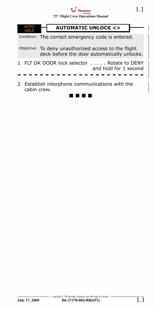
1 FLT DK DOOR lock selector . . . . . Rotate to DENYand hold for 1 second
- - - - - - - - - - - - - - - - - - - - - - -2 Establish interphone communications with the
cabin crew.
AUTOUNLK
AUTOMATIC UNLOCK <>
Condition: The correct emergency code is entered.
Objective: To deny unauthorized access to the flight deck before the door automatically unlocks.
July 17, 2009
::::::::::::::::::::::
737 Flight Crew Operations Manual
Copyright © The Boeing Company. See title page for details.
D6-27370-804-BRI(P2)
1.2
1.2
FWD CARGOAFT CARGO
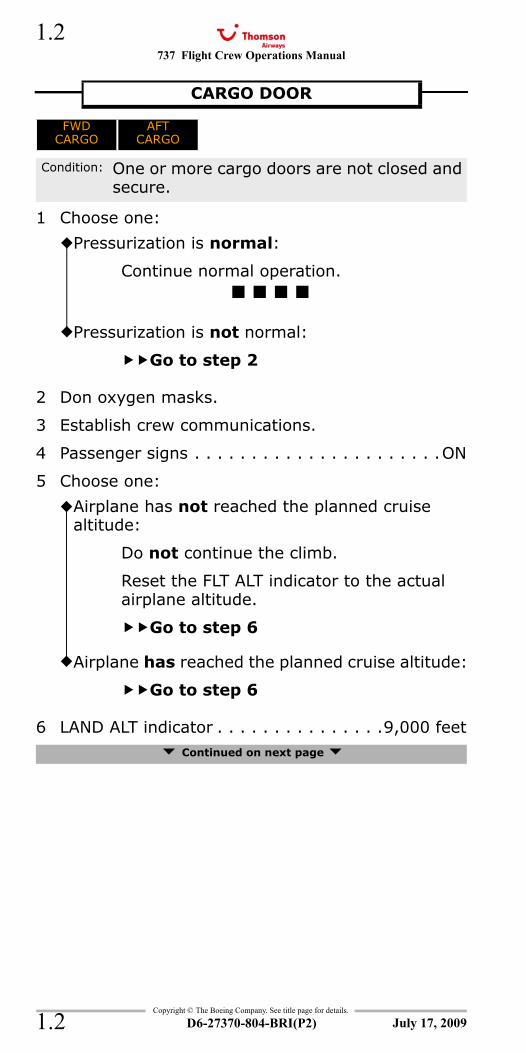
1 Choose one:
2 Don oxygen masks.
3 Establish crew communications.
4 Passenger signs . . . . . . . . . . . . . . . . . . . . . .ON
5 Choose one:
6 LAND ALT indicator . . . . . . . . . . . . . . .9,000 feet Continued on next page
CARGO DOOR
FWDCARGO
AFTCARGO
Condition: One or more cargo doors are not closed and secure.
Pressurization is normal:
Continue normal operation.
Pressurization is not normal:
Go to step 2
Airplane has not reached the planned cruise altitude:
Do not continue the climb.
Reset the FLT ALT indicator to the actual airplane altitude.
Go to step 6
Airplane has reached the planned cruise altitude:
Go to step 6
July 17, 2009
737 Flight Crew Operations Manual 1.3
Copyright © The Boeing Company. See title page for details.
D6-27370-804-BRI(P2) 1.3
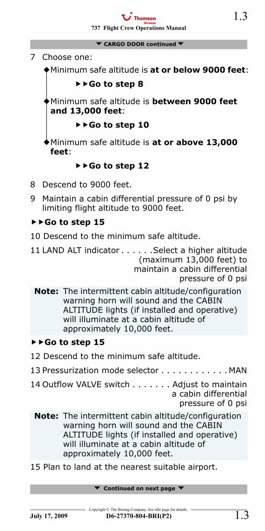
7 Choose one:
8 Descend to 9000 feet.
9 Maintain a cabin differential pressure of 0 psi by limiting flight altitude to 9000 feet.
Go to step 15
10 Descend to the minimum safe altitude.
11 LAND ALT indicator . . . . . .Select a higher altitude(maximum 13,000 feet) to
maintain a cabin differentialpressure of 0 psi
Go to step 15
12 Descend to the minimum safe altitude.
13 Pressurization mode selector . . . . . . . . . . . .MAN
14 Outflow VALVE switch . . . . . . . Adjust to maintaina cabin differential
pressure of 0 psi
15 Plan to land at the nearest suitable airport.
Continued on next page
CARGO DOOR continued
Minimum safe altitude is at or below 9000 feet:
Go to step 8
Minimum safe altitude is between 9000 feet and 13,000 feet:
Go to step 10
Minimum safe altitude is at or above 13,000 feet:
Go to step 12
Note: The intermittent cabin altitude/configuration warning horn will sound and the CABIN ALTITUDE lights (if installed and operative) will illuminate at a cabin altitude of approximately 10,000 feet.
Note: The intermittent cabin altitude/configuration warning horn will sound and the CABIN ALTITUDE lights (if installed and operative) will illuminate at a cabin altitude of approximately 10,000 feet.
July 17, 2009
737 Flight Crew Operations Manual
Copyright © The Boeing Company. See title page for details.
D6-27370-804-BRI(P2)
1.4
1.4
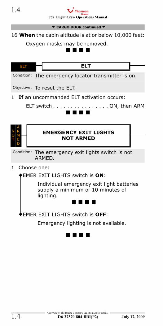
16 When the cabin altitude is at or below 10,000 feet:
Oxygen masks may be removed.
ELT
1 If an uncommanded ELT activation occurs:
ELT switch . . . . . . . . . . . . . . . . ON, then ARM
NOT ARMED
1 Choose one:
CARGO DOOR continued
ELT ELT
Condition: The emergency locator transmitter is on.
Objective: To reset the ELT.
NOT
A R MED
EMERGENCY EXIT LIGHTS NOT ARMED
Condition: The emergency exit lights switch is not ARMED.
EMER EXIT LIGHTS switch is ON:
Individual emergency exit light batteries supply a minimum of 10 minutes of lighting.
EMER EXIT LIGHTS switch is OFF:
Emergency lighting is not available.
July 17, 2009
737 Flight Crew Operations Manual 1.5
Copyright © The Boeing Company. See title page for details.
D6-27370-804-BRI(P2) 1.5
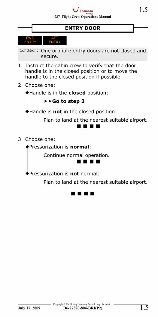
FWD ENTRYAFT ENTRY
1 Instruct the cabin crew to verify that the door handle is in the closed position or to move the handle to the closed position if possible.
2 Choose one:
3 Choose one:
ENTRY DOOR
FWDENTRY
AFTENTRY
Condition: One or more entry doors are not closed and secure.
Handle is in the closed position:
Go to step 3
Handle is not in the closed position:
Plan to land at the nearest suitable airport.
Pressurization is normal:
Continue normal operation.
Pressurization is not normal:
Plan to land at the nearest suitable airport.
July 17, 2009
737 Flight Crew Operations Manual
Copyright © The Boeing Company. See title page for details.
D6-27370-804-BRI(P2)
1.6
1.6
EQUIP
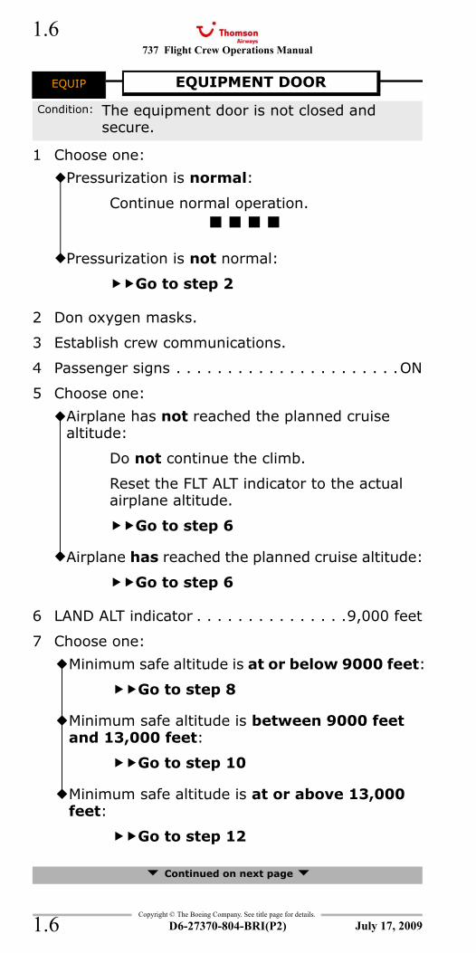
1 Choose one:
2 Don oxygen masks.
3 Establish crew communications.
4 Passenger signs . . . . . . . . . . . . . . . . . . . . . .ON
5 Choose one:
6 LAND ALT indicator . . . . . . . . . . . . . . .9,000 feet
7 Choose one:
Continued on next page
EQUIP EQUIPMENT DOOR
Condition: The equipment door is not closed and secure.
Pressurization is normal:
Continue normal operation.
Pressurization is not normal:
Go to step 2
Airplane has not reached the planned cruise altitude:
Do not continue the climb.
Reset the FLT ALT indicator to the actual airplane altitude.
Go to step 6
Airplane has reached the planned cruise altitude:
Go to step 6
Minimum safe altitude is at or below 9000 feet:
Go to step 8
Minimum safe altitude is between 9000 feet and 13,000 feet:
Go to step 10
Minimum safe altitude is at or above 13,000 feet:
Go to step 12
July 17, 2009
737 Flight Crew Operations Manual 1.7
Copyright © The Boeing Company. See title page for details.
D6-27370-804-BRI(P2) 1.7
8 Descend to 9000 feet.
9 Maintain a cabin differential pressure of 0 psi by limiting flight altitude to 9000 feet.
Go to step 15
10 Descend to the minimum safe altitude.
11 LAND ALT indicator . . . . . .Select a higher altitude(maximum 13,000 feet) to
maintain a cabin differentialpressure of 0 psi
Go to step 15
12 Descend to the minimum safe altitude.
13 Pressurization mode selector . . . . . . . . . . . .MAN
14 Outflow VALVE switch . . . . . . . Adjust to maintaina cabin differential
pressure of 0 psi
15 Plan to land at the nearest suitable airport.
16 When the cabin altitude is at or below 10,000 feet:
Oxygen masks may be removed.
EQUIPMENT DOOR continued
Note: The intermittent cabin altitude/configuration warning horn will sound and the CABIN ALTITUDE lights (if installed and operative) will illuminate at a cabin altitude of approximately 10,000 feet.
Note: The intermittent cabin altitude/configuration warning horn will sound and the CABIN ALTITUDE lights (if installed and operative) will illuminate at a cabin altitude of approximately 10,000 feet.
July 17, 2009
737 Flight Crew Operations Manual
Copyright © The Boeing Company. See title page for details.
D6-27370-804-BRI(P2)
1.8
1.8
LOCK FAIL
1 If conditions allow:
FLIGHT DECK ACCESS SYSTEM switch . . . OFF
LEFT FWD OVERWINGLEFT AFT OVERWINGRIGHT FWD OVERWINGRIGHT AFT OVERWING
1 Choose one:
PASS OXY ON
LOCKFAIL
LOCK FAIL
Condition: One or more of these occur:•The FLIGHT DECK ACCESS SYSTEM switch is OFF
•The lock is failed.
Objective: To remove power from the lock to prevent a possible overheat.
Note: The door can be locked with the dead bolt.
OVERWING DOOR
LEFT FWDOVERWING
LEFT AFTOVERWING
RIGHT FWDOVERWING
RIGHT AFTOVERWING
Condition: One or more overwing doors are not closed and secure.
Pressurization is normal:
Continue normal operation.
Pressurization is not normal:
Plan to land at the nearest suitable airport.
PASS OXYON
PASSENGER OXYGEN ON
Condition: The passenger oxygen system is on.
July 17, 2009
737 Flight Crew Operations Manual 1.9
Copyright © The Boeing Company. See title page for details.
D6-27370-804-BRI(P2) 1.9
FWD SERVICEAFT SERVICE
1 Instruct the cabin crew to verify that the door handle is in the closed position or to move the handle to the closed position if possible.
2 Choose one:
3 Choose one:
or Tailstrike On Takeoff 15.5
SERVICE DOOR
FWDSERVICE
AFTSERVICE
Condition: One or more service doors are not closed and secure.
Handle is in the closed position:
Go to step 3
Handle is not in the closed position:
Plan to land at the nearest suitable airport.
Pressurization is normal:
Continue normal operation.
Pressurization is not normal:
Plan to land at the nearest suitable airport.
July 17, 2009
737 Flight Crew Operations Manual
Copyright © The Boeing Company. See title page for details.
D6-27370-804-BRI(P2)
1.10
1.10
1 Choose one:
2 Don seat belts and shoulder harnesses.
3 WINDOW HEAT switch(affected window). . . . . . . . . . . . . . . . . . . . OFF
Limit airspeed to 250 knots maximum below 10,000 feet.
4 Pull both WINDSHIELD AIR controls. This vents conditioned air to the inside of the windshield for defogging.
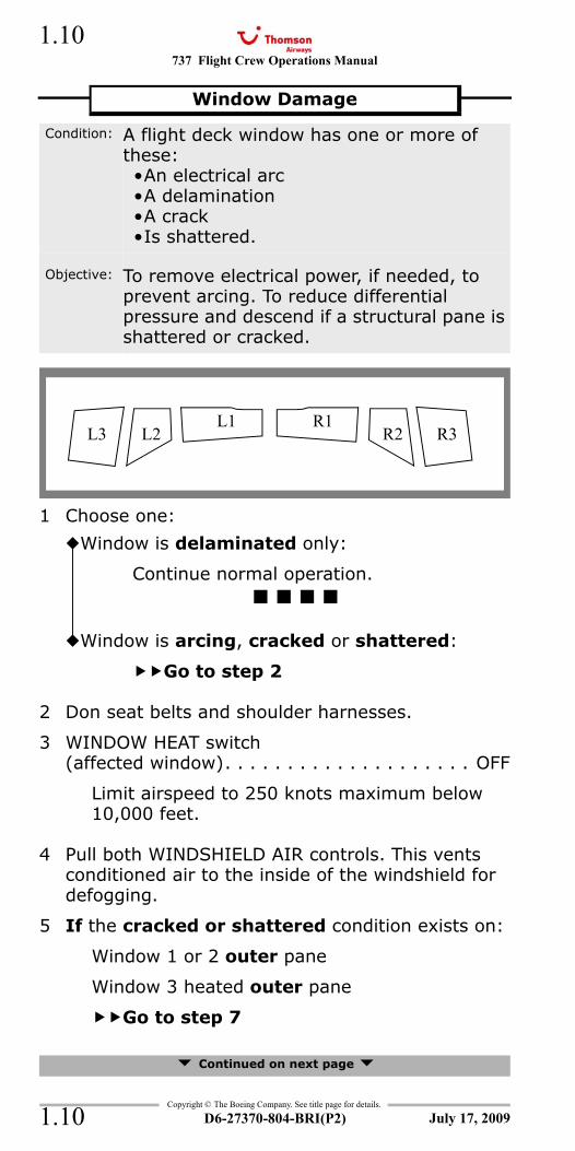
5 If the cracked or shattered condition exists on:
Window 1 or 2 outer pane
Window 3 heated outer pane
Go to step 7
Continued on next page
Window Damage
Condition: A flight deck window has one or more of these:•An electrical arc•A delamination•A crack•Is shattered.
Objective: To remove electrical power, if needed, to prevent arcing. To reduce differential pressure and descend if a structural pane is shattered or cracked.
Window is delaminated only:
Continue normal operation.
Window is arcing, cracked or shattered:
Go to step 2
L3 L2L1 R1
R2 R3
July 17, 2009
737 Flight Crew Operations Manual 1.11
Copyright © The Boeing Company. See title page for details.
D6-27370-804-BRI(P2) 1.11
6 If the cracked or shattered condition exists on:
Window 1 or 2 inner pane
Window 3 heated inner pane
Go to step 9
7 Continue normal operation.
8 Shoulder harnesses may be removed.
9 Don oxygen masks.
10 Establish crew communications.
11 Passenger signs . . . . . . . . . . . . . . . . . . . . . . ON
12 Choose one:
13 LAND ALT indicator . . . . . . . . . . . . . . .9,000 feet
14 Start a normal descent to below 14,000 feet or to the minimum safe altitude, whichever is higher.
15 Plan to land at the nearest suitable airport.
16 When cabin differential pressure is 2 psi or less:
Oxygen masks and shoulder harnesses may be removed.
17 Sustained flight below 10,000 feet is not recommended due to the greater risk of a bird strike.
Window Damage continued
Airplane has not reached the planned cruise altitude:
Do not continue the climb.
Reset the FLT ALT indicator to the actual airplane altitude.
Go to step 13
Airplane has reached the planned cruise altitude:
Go to step 13
July 17, 2009
737 Flight Crew Operations Manual
Copyright © The Boeing Company. See title page for details.
D6-27370-804-BRI(P2)
1.12
1.12
1 Maintain the maneuvering speed for the existing flap setting until the window is closed.
2 The force needed to close the window increases with airspeed. It may not be possible to close the window at speeds above 250 knots.
3 Close and lock the window.
4 Choose one:
Window Open
Condition: A side window opens during takeoff or in flight.
Window locks and the pressurization is normal:
Continue normal operation.
Window does not lock or the pressurization is not normal:
Level off at the lowest safe altitude.
The airplane can fly unpressurized and land safely with the window open.
July 17, 2009
737 Flight Crew Operations Manual
Non-Normal Checklists Chapter NNCAir Systems Section 2
Table of Contents
Copyright © The Boeing Company. See title page for details.
D6-27370-804-BRI(P2) 2.TOC.1
CABIN ALTITUDE WARNING or Rapid Depressurization .........................2.1
Emergency Descent................... 0.5Smoke, Fire or Fumes ............... 8.8
AUTO FAIL or Unscheduled PressurizationChange <> ..................................................2.2
BLEED TRIP OFF...............................................2.5
CABIN ALTITUDE WARNING or Rapid Depressurization .........................2.1
DUAL BLEED....................................................2.6
Emergency Descent................... 0.5EQUIPMENT COOLING OFF ................................2.6OFF SCHEDULE DESCENT..................................2.7PACK..............................................................2.8
Smoke, Fire or Fumes ............... 8.8WING-BODY OVERHEAT ..................................2.10ZONE TEMP ...................................................2.13
July 17, 2009
NNC.2-Air SystemsTable Of Contents
737 Flight Crew Operations Manual
Non-Normal Checklists -Air Systems
Table of Contents
Copyright © The Boeing Company. See title page for details.
D6-27370-804-BRI(P2)2.TOC.2
IntentionallyBlank
July 17, 2009
737 Flight Crew Operations Manual 2.1
Copyright © The Boeing Company. See title page for details.
D6-27370-804-BRI(P2) 2.1
NNC.2 Non-Normal Checklists-Air SystemsCABIN ALTITUDE
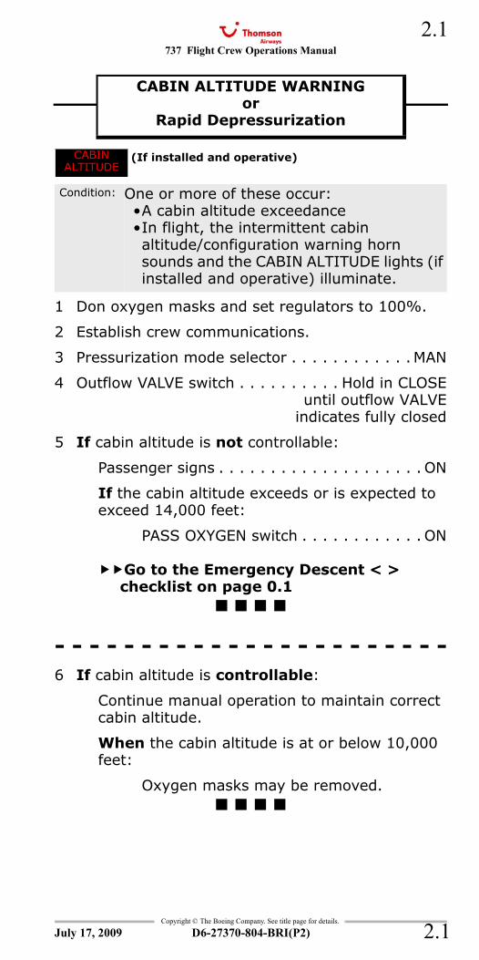
1 Don oxygen masks and set regulators to 100%.
2 Establish crew communications.
3 Pressurization mode selector . . . . . . . . . . . .MAN
4 Outflow VALVE switch . . . . . . . . . . Hold in CLOSEuntil outflow VALVE
indicates fully closed
5 If cabin altitude is not controllable:
Passenger signs . . . . . . . . . . . . . . . . . . . . ON
If the cabin altitude exceeds or is expected to exceed 14,000 feet:
PASS OXYGEN switch . . . . . . . . . . . . ON
Go to the Emergency Descent < > checklist on page 0.1
- - - - - - - - - - - - - - - - - - - - - - -6 If cabin altitude is controllable:
Continue manual operation to maintain correct cabin altitude.
When the cabin altitude is at or below 10,000 feet:
Oxygen masks may be removed.
Emergency Descent 0.5Smoke, Fire or Fumes 8.8
CABIN ALTITUDE WARNINGor
Rapid DepressurizationCABIN ALTITUDE WARNING or Rapid Depressurization
CABIN ALTITUDE
(If installed and operative)
Condition: One or more of these occur:•A cabin altitude exceedance•In flight, the intermittent cabin altitude/configuration warning horn sounds and the CABIN ALTITUDE lights (if installed and operative) illuminate.
July 17, 2009
737 Flight Crew Operations Manual
Copyright © The Boeing Company. See title page for details.
D6-27370-804-BRI(P2)
2.2
2.2
AUTO FAIL
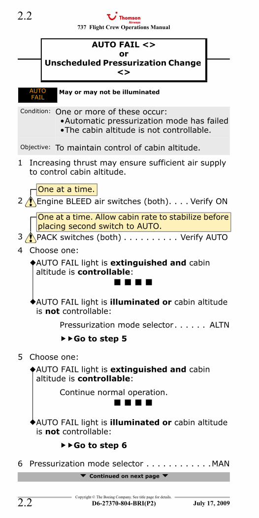
1 Increasing thrust may ensure sufficient air supply to control cabin altitude.
4 Choose one:
5 Choose one:
6 Pressurization mode selector . . . . . . . . . . . .MAN Continued on next page
AUTO FAIL <>or
Unscheduled Pressurization Change <>
AUTO FAIL or Unscheduled Pressurization Change <>
AUTOFAIL
May or may not be illuminated
Condition: One or more of these occur:•Automatic pressurization mode has failed•The cabin altitude is not controllable.
Objective: To maintain control of cabin altitude.
One at a time.2 Engine BLEED air switches (both). . . . Verify ON
One at a time. Allow cabin rate to stabilize before placing second switch to AUTO.
3 PACK switches (both) . . . . . . . . . . Verify AUTO
AUTO FAIL light is extinguished and cabin altitude is controllable:
AUTO FAIL light is illuminated or cabin altitude is not controllable:
Pressurization mode selector. . . . . . ALTN
Go to step 5
AUTO FAIL light is extinguished and cabin altitude is controllable:
Continue normal operation.
AUTO FAIL light is illuminated or cabin altitude is not controllable:
Go to step 6
July 17, 2009
737 Flight Crew Operations Manual 2.3
Copyright © The Boeing Company. See title page for details.
D6-27370-804-BRI(P2) 2.3
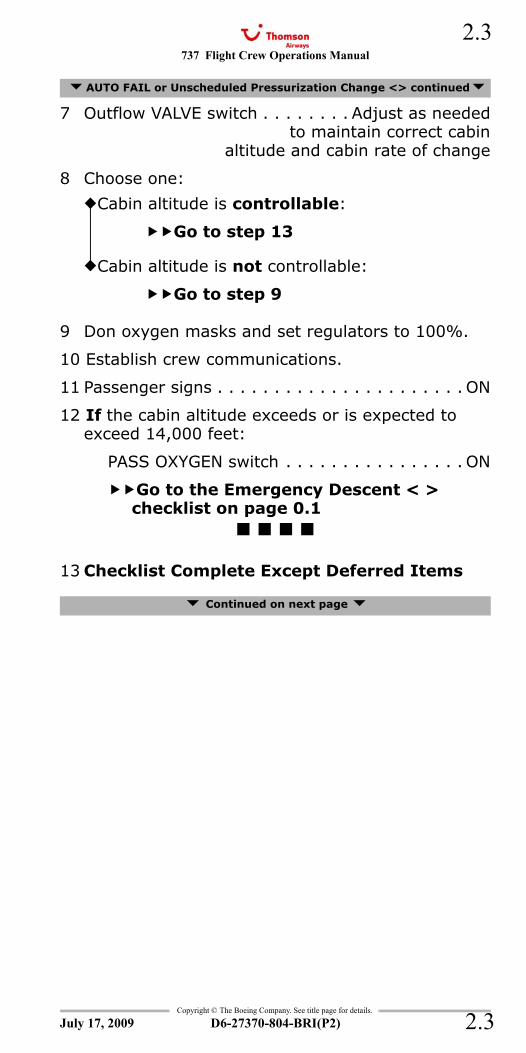
7 Outflow VALVE switch . . . . . . . . Adjust as neededto maintain correct cabin
altitude and cabin rate of change
8 Choose one:
9 Don oxygen masks and set regulators to 100%.
10 Establish crew communications.
11 Passenger signs . . . . . . . . . . . . . . . . . . . . . . ON
12 If the cabin altitude exceeds or is expected to exceed 14,000 feet:
PASS OXYGEN switch . . . . . . . . . . . . . . . . ON
Go to the Emergency Descent < > checklist on page 0.1
13 Checklist Complete Except Deferred Items
Continued on next page
AUTO FAIL or Unscheduled Pressurization Change <> continued
Cabin altitude is controllable:
Go to step 13
Cabin altitude is not controllable:
Go to step 9
July 17, 2009
737 Flight Crew Operations Manual
Copyright © The Boeing Company. See title page for details.
D6-27370-804-BRI(P2)
2.4
2.4
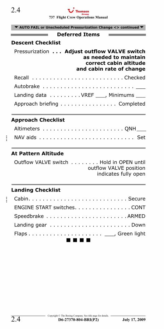
Descent Checklist
Pressurization . . . Adjust outflow VALVE switchas needed to maintaincorrect cabin altitude
and cabin rate of change
Recall . . . . . . . . . . . . . . . . . . . . . . . . . . Checked
Autobrake . . . . . . . . . . . . . . . . . . . . . . . . . . ___
Landing data . . . . . . . . . VREF ___, Minimums ___
Approach briefing . . . . . . . . . . . . . . . . Completed
Approach Checklist
Altimeters . . . . . . . . . . . . . . . . . . . . . . . QNH___
NAV aids . . . . . . . . . . . . . . . . . . . . . . . . . . . Set
At Pattern Altitude
Outflow VALVE switch . . . . . . . . Hold in OPEN untiloutflow VALVE position
indicates fully open
Landing Checklist
Cabin. . . . . . . . . . . . . . . . . . . . . . . . . . . . Secure
ENGINE START switches. . . . . . . . . . . . . . . . CONT
Speedbrake . . . . . . . . . . . . . . . . . . . . . . . ARMED
Landing gear . . . . . . . . . . . . . . . . . . . . . . . Down
Flaps . . . . . . . . . . . . . . . . . . . . . ___, Green light
AUTO FAIL or Unscheduled Pressurization Change <> continued
Deferred Items
July 17, 2009
::::
::::
737 Flight Crew Operations Manual 2.5
Copyright © The Boeing Company. See title page for details.
D6-27370-804-BRI(P2) 2.5
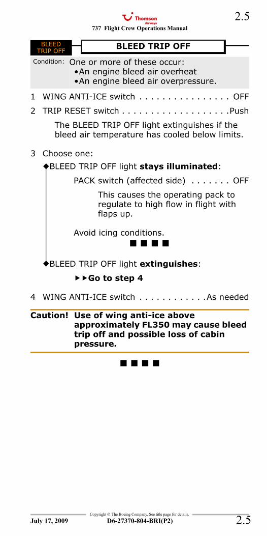
BLEED TRIP OFF
1 WING ANTI-ICE switch . . . . . . . . . . . . . . . . OFF
2 TRIP RESET switch . . . . . . . . . . . . . . . . . . .Push
The BLEED TRIP OFF light extinguishes if the bleed air temperature has cooled below limits.
3 Choose one:
4 WING ANTI-ICE switch . . . . . . . . . . . .As needed
Caution! Use of wing anti-ice above approximately FL350 may cause bleed trip off and possible loss of cabin pressure.
BLEEDTRIP OFF
BLEED TRIP OFF
Condition: One or more of these occur:•An engine bleed air overheat•An engine bleed air overpressure.
BLEED TRIP OFF light stays illuminated:
PACK switch (affected side) . . . . . . . OFF
This causes the operating pack to regulate to high flow in flight with flaps up.
Avoid icing conditions.
BLEED TRIP OFF light extinguishes:
Go to step 4
July 17, 2009
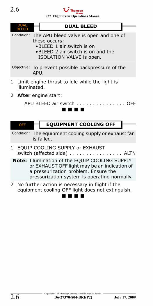
737 Flight Crew Operations Manual
Copyright © The Boeing Company. See title page for details.
D6-27370-804-BRI(P2)
2.6
2.6
DUAL BLEED
1 Limit engine thrust to idle while the light is illuminated.
2 After engine start:
APU BLEED air switch . . . . . . . . . . . . . . . OFF
OFF - Equipment Cooling
1 EQUIP COOLING SUPPLY or EXHAUST switch (affected side) . . . . . . . . . . . . . . . . ALTN
2 No further action is necessary in flight if the equipment cooling OFF light does not extinguish.
DUALBLEED
DUAL BLEED
Condition: The APU bleed valve is open and one of these occurs:•BLEED 1 air switch is on•BLEED 2 air switch is on and the ISOLATION VALVE is open.
Objective: To prevent possible backpressure of the APU.
OFF EQUIPMENT COOLING OFF
Condition: The equipment cooling supply or exhaust fan is failed.
Note: Illumination of the EQUIP COOLING SUPPLY or EXHAUST OFF light may be an indication of a pressurization problem. Ensure the pressurization system is operating normally.
July 17, 2009
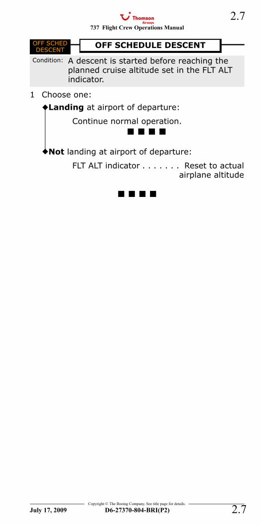
737 Flight Crew Operations Manual 2.7
Copyright © The Boeing Company. See title page for details.
D6-27370-804-BRI(P2) 2.7
OFF SCHED DESCENT
1 Choose one:
OFF SCHEDDESCENT
OFF SCHEDULE DESCENT
Condition: A descent is started before reaching the planned cruise altitude set in the FLT ALT indicator.
Landing at airport of departure:
Continue normal operation.
Not landing at airport of departure:
FLT ALT indicator . . . . . . . Reset to actualairplane altitude
July 17, 2009
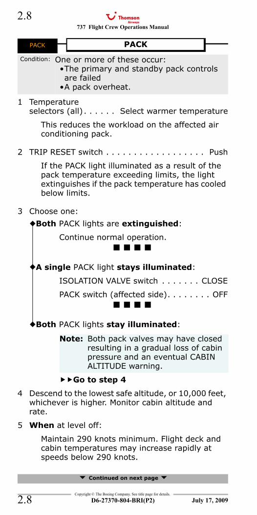
737 Flight Crew Operations Manual
Copyright © The Boeing Company. See title page for details.
D6-27370-804-BRI(P2)
2.8
2.8
PACK
1 Temperature selectors (all) . . . . . . Select warmer temperature
This reduces the workload on the affected air conditioning pack.
2 TRIP RESET switch . . . . . . . . . . . . . . . . . . Push
If the PACK light illuminated as a result of the pack temperature exceeding limits, the light extinguishes if the pack temperature has cooled below limits.
3 Choose one:
4 Descend to the lowest safe altitude, or 10,000 feet, whichever is higher. Monitor cabin altitude and rate.
5 When at level off:
Maintain 290 knots minimum. Flight deck and cabin temperatures may increase rapidly at speeds below 290 knots.
Continued on next page
PACK PACK
Condition: One or more of these occur:•The primary and standby pack controls are failed
•A pack overheat.
Both PACK lights are extinguished:
Continue normal operation.
A single PACK light stays illuminated:
ISOLATION VALVE switch . . . . . . . CLOSE
PACK switch (affected side). . . . . . . . OFF
Both PACK lights stay illuminated:
Note: Both pack valves may have closed resulting in a gradual loss of cabin pressure and an eventual CABIN ALTITUDE warning.
Go to step 4
July 17, 2009
737 Flight Crew Operations Manual 2.9
Copyright © The Boeing Company. See title page for details.
D6-27370-804-BRI(P2) 2.9
6 Choose one:
7 Pressurization mode selector . . . . . . . . . . . .MAN
8 Outflow VALVE switch . . . . . . . Hold in OPEN untiloutflow VALVE position
indicates fully open
This increases airplane ventilation.
9 R RECIRC FAN switch . . . . . . . . . . . . . . . . AUTO
10 L RECIRC FAN switch . . . . . . . . . . . . . . . . . OFF
11 If flight deck and cabin temperatures are excessively warm:
Open the flight deck door. This improves flight deck ventilation.
Use flight deck window shades, as needed.
Instruct the cabin crew to:
Dim cabin lighting.
G-FDZA - G-FDZSTurn off in-flight entertainment systems.
Close cabin window shades.
G-FDZA - G-FDZSCAB/UTIL switch . . . . . . . . . . . . . . . . . . OFF
G-FDZA - G-FDZSIFE/PASS SEAT switch. . . . . . . . . . . . . . . OFF
G-CDZH - G-CDZMGALLEY switch . . . . . . . . . . . . . . . . . . . . OFF
PACK continued
Airplane altitude is at or below 10,000 feet:
Go to step 7
Airplane altitude is above 10,000 feet:
Don oxygen masks.
Establish crew communications.
Go to step 7
July 17, 2009
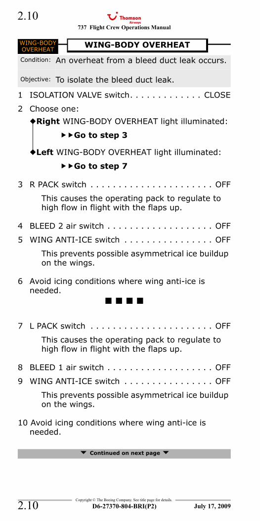
737 Flight Crew Operations Manual
Copyright © The Boeing Company. See title page for details.
D6-27370-804-BRI(P2)
2.10
2.10
WING-BODY OVERHEAT
1 ISOLATION VALVE switch. . . . . . . . . . . . . CLOSE
2 Choose one:
3 R PACK switch . . . . . . . . . . . . . . . . . . . . . . OFF
This causes the operating pack to regulate to high flow in flight with the flaps up.
4 BLEED 2 air switch . . . . . . . . . . . . . . . . . . . OFF
5 WING ANTI-ICE switch . . . . . . . . . . . . . . . . OFF
This prevents possible asymmetrical ice buildup on the wings.
6 Avoid icing conditions where wing anti-ice is needed.
7 L PACK switch . . . . . . . . . . . . . . . . . . . . . . OFF
This causes the operating pack to regulate to high flow in flight with the flaps up.
8 BLEED 1 air switch . . . . . . . . . . . . . . . . . . . OFF
9 WING ANTI-ICE switch . . . . . . . . . . . . . . . . OFF
This prevents possible asymmetrical ice buildup on the wings.
10 Avoid icing conditions where wing anti-ice is needed.
Continued on next page
WING-BODYOVERHEAT
WING-BODY OVERHEAT
Condition: An overheat from a bleed duct leak occurs.
Objective: To isolate the bleed duct leak.
Right WING-BODY OVERHEAT light illuminated:
Go to step 3
Left WING-BODY OVERHEAT light illuminated:
Go to step 7
July 17, 2009
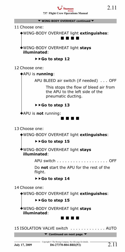
737 Flight Crew Operations Manual 2.11
Copyright © The Boeing Company. See title page for details.
D6-27370-804-BRI(P2) 2.11
11 Choose one:
12 Choose one:
13 Choose one:
14 Choose one:
15 ISOLATION VALVE switch . . . . . . . . . . . . . AUTO Continued on next page
WING-BODY OVERHEAT continued
WING-BODY OVERHEAT light extinguishes:
WING-BODY OVERHEAT light stays illuminated:
Go to step 12
APU is running:
APU BLEED air switch (if needed) . . . OFF
This stops the flow of bleed air from the APU to the left side of the pneumatic ducting.
Go to step 13
APU is not running:
WING-BODY OVERHEAT light extinguishes:
Go to step 15
WING-BODY OVERHEAT light stays illuminated:
APU switch . . . . . . . . . . . . . . . . . . . OFF
Do not start the APU for the rest of the flight.
Go to step 14
WING-BODY OVERHEAT light extinguishes:
Go to step 15
WING-BODY OVERHEAT light stays illuminated:
July 17, 2009
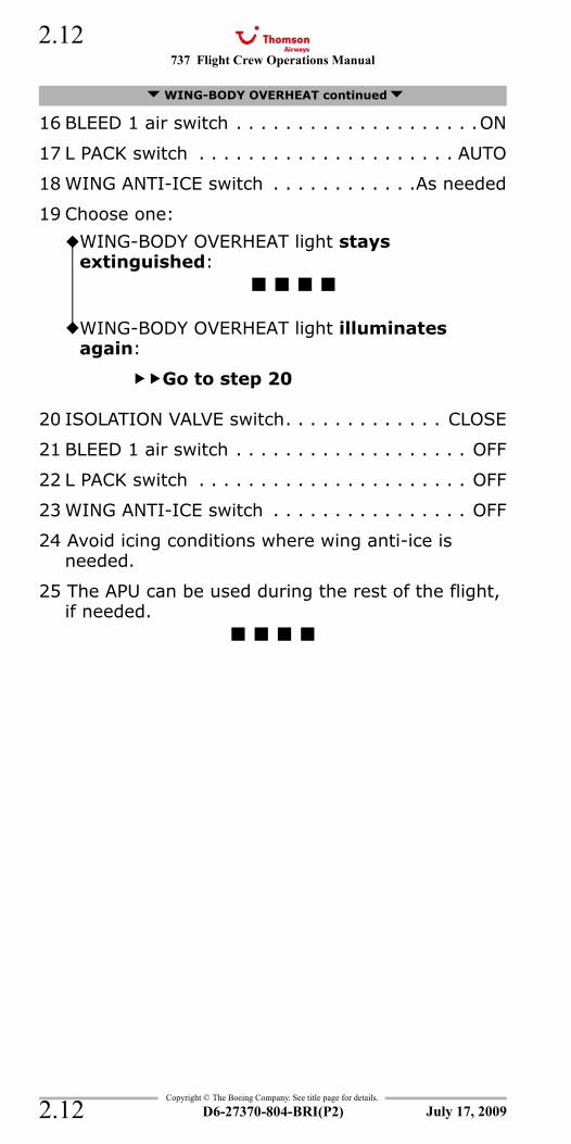
737 Flight Crew Operations Manual
Copyright © The Boeing Company. See title page for details.
D6-27370-804-BRI(P2)
2.12
2.12
16 BLEED 1 air switch . . . . . . . . . . . . . . . . . . . .ON
17 L PACK switch . . . . . . . . . . . . . . . . . . . . . AUTO
18 WING ANTI-ICE switch . . . . . . . . . . . .As needed
19 Choose one:
20 ISOLATION VALVE switch. . . . . . . . . . . . . CLOSE
21 BLEED 1 air switch . . . . . . . . . . . . . . . . . . . OFF
22 L PACK switch . . . . . . . . . . . . . . . . . . . . . . OFF
23 WING ANTI-ICE switch . . . . . . . . . . . . . . . . OFF
24 Avoid icing conditions where wing anti-ice is needed.
25 The APU can be used during the rest of the flight, if needed.
WING-BODY OVERHEAT continued
WING-BODY OVERHEAT light stays extinguished:
WING-BODY OVERHEAT light illuminates again:
Go to step 20
July 17, 2009
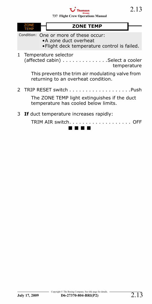
737 Flight Crew Operations Manual 2.13
Copyright © The Boeing Company. See title page for details.
D6-27370-804-BRI(P2) 2.13
ZONE TEMP
1 Temperature selector(affected cabin) . . . . . . . . . . . . . .Select a cooler
temperature
This prevents the trim air modulating valve from returning to an overheat condition.
2 TRIP RESET switch . . . . . . . . . . . . . . . . . . .Push
The ZONE TEMP light extinguishes if the duct temperature has cooled below limits.
3 If duct temperature increases rapidly:
TRIM AIR switch. . . . . . . . . . . . . . . . . . . OFF
ZONETEMP
ZONE TEMP
Condition: One or more of these occur:•A zone duct overheat•Flight deck temperature control is failed.
July 17, 2009

737 Flight Crew Operations Manual
Copyright © The Boeing Company. See title page for details.
D6-27370-804-BRI(P2)
2.14
2.14
IntentionallyBlank
July 17, 2009
737 Flight Crew Operations Manual
Non-Normal Checklists Chapter NNCAnti-Ice, Rain Section 3
Table of Contents
Copyright © The Boeing Company. See title page for details.
D6-27370-804-BRI(P2) 3.TOC.1
ENGINE COWL ANTI-ICE ...................................3.1ENGINE COWL VALVE OPEN OR TAI INDICATION..3.1PROBE HEAT....................................................3.2WINDOW HEAT OFF..........................................3.2WINDOW OVERHEAT ........................................3.3WING ANTI-ICE VALVE OPEN.............................3.4
July 17, 2009
NNC.3-Anti-Ice, RainTable Of Contents

737 Flight Crew Operations Manual
Non-Normal Checklists -Anti-Ice, Rain
Table of Contents
Copyright © The Boeing Company. See title page for details.
D6-27370-804-BRI(P2)3.TOC.2
IntentionallyBlank
July 17, 2009
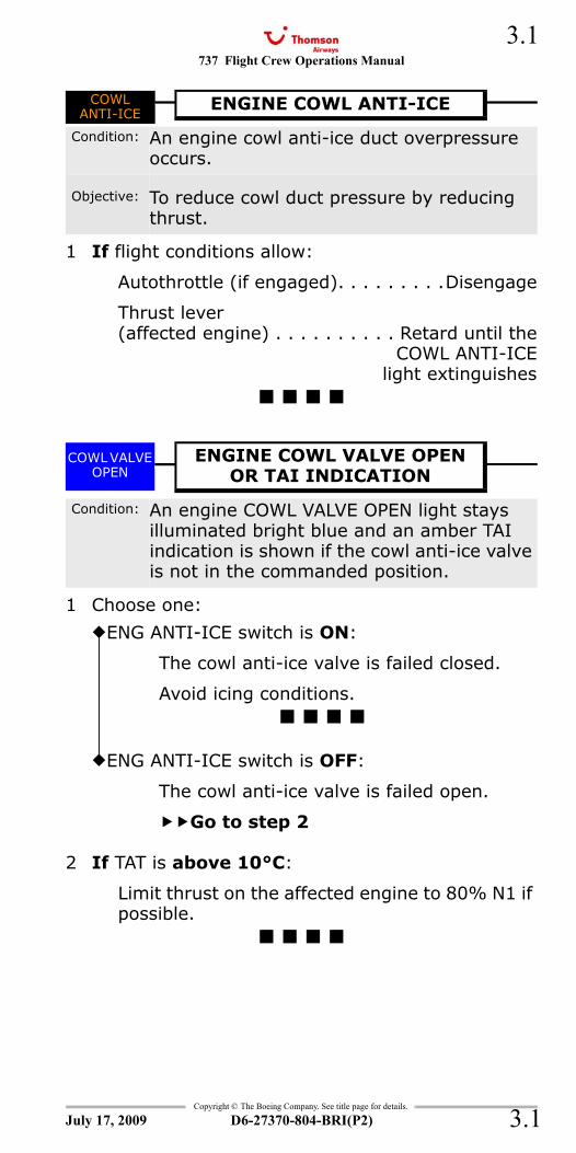
737 Flight Crew Operations Manual 3.1
Copyright © The Boeing Company. See title page for details.
D6-27370-804-BRI(P2) 3.1
NNC.3 Non-Normal Checklists-Anti-Ice, RainCOWL ANTI-ICE
1 If flight conditions allow:
Autothrottle (if engaged). . . . . . . . .Disengage
Thrust lever(affected engine) . . . . . . . . . . Retard until the
COWL ANTI-ICElight extinguishes
COWL VALVE OPEN - Engine Anti-iceTAI
1 Choose one:
2 If TAT is above 10°C:
Limit thrust on the affected engine to 80% N1 if possible.
COWLANTI-ICE
ENGINE COWL ANTI-ICE
Condition: An engine cowl anti-ice duct overpressure occurs.
Objective: To reduce cowl duct pressure by reducing thrust.
COWL VALVE OPEN
ENGINE COWL VALVE OPEN OR TAI INDICATION
Condition: An engine COWL VALVE OPEN light stays illuminated bright blue and an amber TAI indication is shown if the cowl anti-ice valve is not in the commanded position.
ENG ANTI-ICE switch is ON:
The cowl anti-ice valve is failed closed.
Avoid icing conditions.
ENG ANTI-ICE switch is OFF:
The cowl anti-ice valve is failed open.
Go to step 2
July 17, 2009
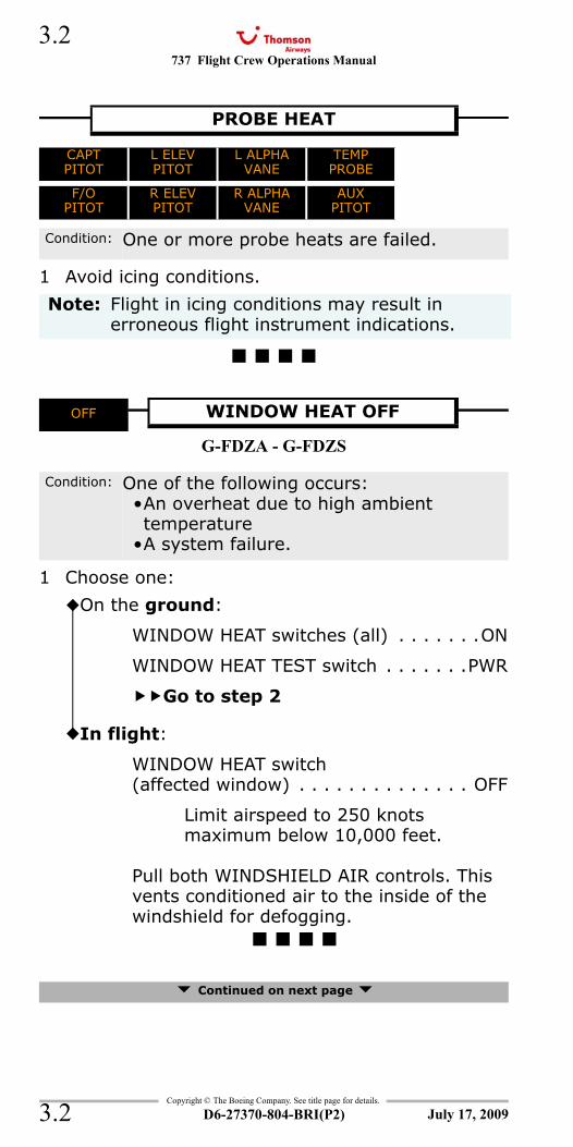
737 Flight Crew Operations Manual
Copyright © The Boeing Company. See title page for details.
D6-27370-804-BRI(P2)
3.2
3.2
CAPT PITOTL ELEV PITOTL ALPHA VANETEMP PROBEF/O PITOTR ELEV PITOTR ALPHA VANEAUX PITOT
1 Avoid icing conditions.
OFF - Window Heat
G-FDZA - G-FDZS
1 Choose one:
Continued on next page
PROBE HEAT
CAPTPITOT
L ELEVPITOT
L ALPHA VANE
TEMPPROBE
F/OPITOT
R ELEVPITOT
R ALPHA VANE
AUXPITOT
Condition: One or more probe heats are failed.
Note: Flight in icing conditions may result in erroneous flight instrument indications.
OFF WINDOW HEAT OFF
Condition: One of the following occurs:•An overheat due to high ambient temperature
•A system failure.
On the ground:
WINDOW HEAT switches (all) . . . . . . .ON
WINDOW HEAT TEST switch . . . . . . .PWR
Go to step 2
In flight:
WINDOW HEAT switch(affected window) . . . . . . . . . . . . . . OFF
Limit airspeed to 250 knots maximum below 10,000 feet.
Pull both WINDSHIELD AIR controls. This vents conditioned air to the inside of the windshield for defogging.
July 17, 2009
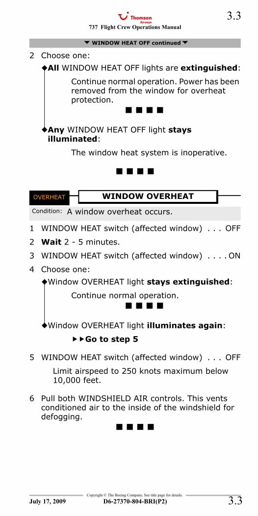
737 Flight Crew Operations Manual 3.3
Copyright © The Boeing Company. See title page for details.
D6-27370-804-BRI(P2) 3.3
2 Choose one:
OVERHEAT - Window
1 WINDOW HEAT switch (affected window) . . . OFF
2 Wait 2 - 5 minutes.
3 WINDOW HEAT switch (affected window) . . . . ON
4 Choose one:
5 WINDOW HEAT switch (affected window) . . . OFF
Limit airspeed to 250 knots maximum below 10,000 feet.
6 Pull both WINDSHIELD AIR controls. This vents conditioned air to the inside of the windshield for defogging.
WINDOW HEAT OFF continued
All WINDOW HEAT OFF lights are extinguished:
Continue normal operation. Power has been removed from the window for overheat protection.
Any WINDOW HEAT OFF light stays illuminated:
The window heat system is inoperative.
OVERHEAT WINDOW OVERHEAT
Condition: A window overheat occurs.
Window OVERHEAT light stays extinguished:
Continue normal operation.
Window OVERHEAT light illuminates again:
Go to step 5
July 17, 2009
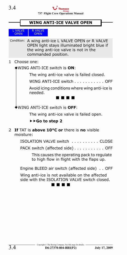
737 Flight Crew Operations Manual
Copyright © The Boeing Company. See title page for details.
D6-27370-804-BRI(P2)
3.4
3.4
L VALVE OPEN - Wing Anti-iceR VALVE OPEN - Wing Anti-ice
1 Choose one:
2 If TAT is above 10°C or there is no visible moisture:
ISOLATION VALVE switch . . . . . . . . . . CLOSE
PACK switch (affected side) . . . . . . . . . . . OFF
This causes the operating pack to regulate to high flow in flight with the flaps up.
Engine BLEED air switch (affected side) . . OFF
Wing anti-ice is not available on the affected side with the ISOLATION VALVE switch closed.
WING ANTI-ICE VALVE OPEN
L VALVEOPEN
R VALVEOPEN
Condition: A wing anti-ice L VALVE OPEN or R VALVE OPEN light stays illuminated bright blue if the wing anti-ice valve is not in the commanded position.
WING ANTI-ICE switch is ON:
The wing anti-ice valve is failed closed.
WING ANTI-ICE switch . . . . . . . . . . . OFF
Avoid icing conditions where wing anti-ice is needed.
WING ANTI-ICE switch is OFF:
The wing anti-ice valve is failed open.
Go to step 2
July 17, 2009
737 Flight Crew Operations Manual
Non-Normal Checklists Chapter NNCAutomatic Flight Section 4
Table of Contents
Copyright © The Boeing Company. See title page for details.
D6-27370-804-BRI(P2) 4.TOC.1
AUTOPILOT DISENGAGE ...................................4.1AUTOTHROTTLE DISENGAGE .............................4.1NO AUTOLAND.................................................4.1NO LAND 3......................................................4.1
July 17, 2009
NNC.4-Automatic FlightTable Of Contents

737 Flight Crew Operations Manual
Non-Normal Checklists -Automatic Flight
Table of Contents
Copyright © The Boeing Company. See title page for details.
D6-27370-804-BRI(P2)4.TOC.2
IntentionallyBlank
July 17, 2009
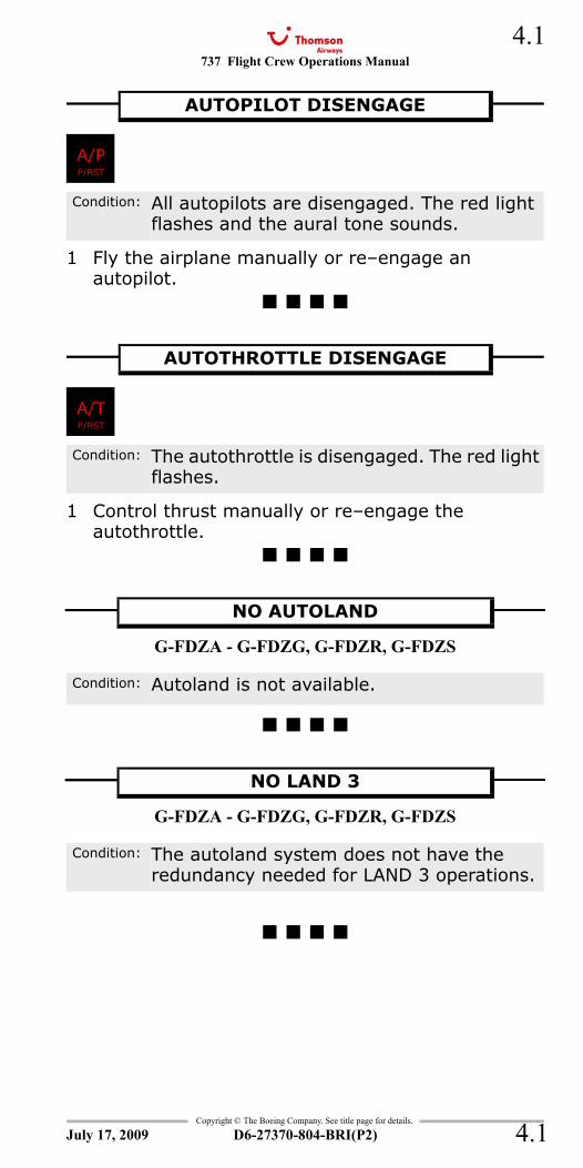
737 Flight Crew Operations Manual 4.1
Copyright © The Boeing Company. See title page for details.
D6-27370-804-BRI(P2) 4.1
NNC.4 Non-Normal Checklists-Automatic FlightA/P
1 Fly the airplane manually or re–engage an autopilot.
A/T
1 Control thrust manually or re–engage the autothrottle.
NO AUTOLAND
G-FDZA - G-FDZG, G-FDZR, G-FDZS
NO LAND 3
G-FDZA - G-FDZG, G-FDZR, G-FDZS
AUTOPILOT DISENGAGE
A/PP/RST
Condition: All autopilots are disengaged. The red light flashes and the aural tone sounds.
AUTOTHROTTLE DISENGAGE
A/TP/RST
Condition: The autothrottle is disengaged. The red light flashes.
NO AUTOLAND
Condition: Autoland is not available.
NO LAND 3
Condition: The autoland system does not have the redundancy needed for LAND 3 operations.
July 17, 2009

737 Flight Crew Operations Manual
Copyright © The Boeing Company. See title page for details.
D6-27370-804-BRI(P2)
4.2
4.2
IntentionallyBlank
July 17, 2009
737 Flight Crew Operations Manual
Non-Normal Checklists Chapter NNCCommunications Section 5
Table of Contents
Copyright © The Boeing Company. See title page for details.
D6-27370-804-BRI(P2) 5.TOC.1
ACARS Electrical Power Loss ..............................5.1ACARS MU Fail or DU Fail ..................................5.1Radio Transmit Continuous (Stuck
Microphone Switch).......................................5.1
July 17, 2009
NNC.5-CommunicationsTable Of Contents

737 Flight Crew Operations Manual
Non-Normal Checklists -Communications
Table of Contents
Copyright © The Boeing Company. See title page for details.
D6-27370-804-BRI(P2)5.TOC.2
IntentionallyBlank
July 17, 2009
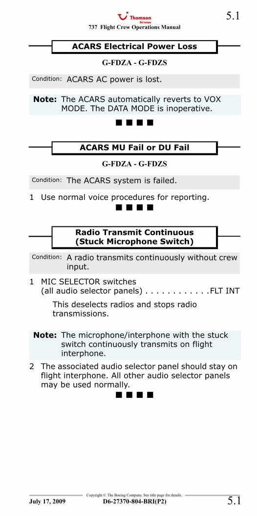
737 Flight Crew Operations Manual 5.1
Copyright © The Boeing Company. See title page for details.
D6-27370-804-BRI(P2) 5.1
NNC.5 Non-Normal Checklists-Communications
G-FDZA - G-FDZS
G-FDZA - G-FDZS
1 Use normal voice procedures for reporting.
1 MIC SELECTOR switches(all audio selector panels) . . . . . . . . . . . .FLT INT
This deselects radios and stops radio transmissions.
2 The associated audio selector panel should stay on flight interphone. All other audio selector panels may be used normally.
ACARS Electrical Power Loss
Condition: ACARS AC power is lost.
Note: The ACARS automatically reverts to VOX MODE. The DATA MODE is inoperative.
ACARS MU Fail or DU Fail
Condition: The ACARS system is failed.
Radio Transmit Continuous(Stuck Microphone Switch)
Condition: A radio transmits continuously without crew input.
Note: The microphone/interphone with the stuck switch continuously transmits on flight interphone.
July 17, 2009

737 Flight Crew Operations Manual
Copyright © The Boeing Company. See title page for details.
D6-27370-804-BRI(P2)
5.2
5.2
IntentionallyBlank
July 17, 2009
737 Flight Crew Operations Manual
Non-Normal Checklists Chapter NNCElectrical Section 6
Table of Contents
Copyright © The Boeing Company. See title page for details.
D6-27370-804-BRI(P2) 6.TOC.1
Smoke, Fire or Fumes ............... 8.8
BATTERY DISCHARGE .......................................6.1DRIVE ............................................................6.1ELEC ..............................................................6.1LOSS OF BOTH ENGINE DRIVEN GENERATORS.....6.2
Smoke, Fire or Fumes ............... 8.8SOURCE OFF ...................................................6.6STANDBY POWER OFF.......................................6.7TR UNIT..........................................................6.7TRANSFER BUS OFF..........................................6.8
July 17, 2009
NNC.6-ElectricalTable Of Contents
737 Flight Crew Operations Manual
Non-Normal Checklists -Electrical
Table of Contents
Copyright © The Boeing Company. See title page for details.
D6-27370-804-BRI(P2)6.TOC.2
IntentionallyBlank
July 17, 2009
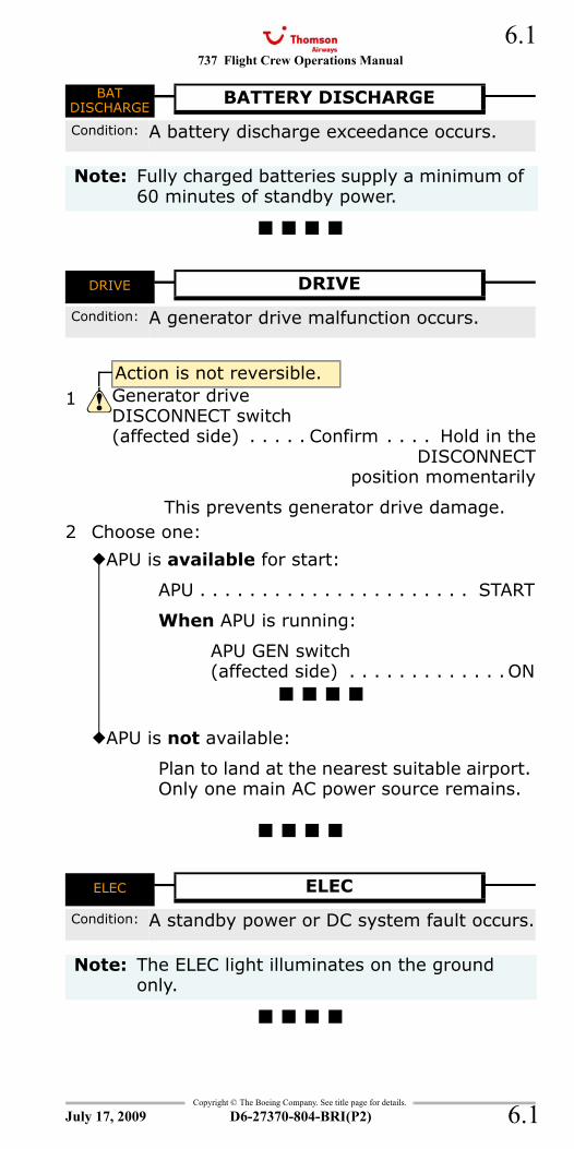
737 Flight Crew Operations Manual 6.1
Copyright © The Boeing Company. See title page for details.
D6-27370-804-BRI(P2) 6.1
NNC.6 Non-Normal Checklists-ElectricalSmoke, Fire or Fumes 8.8
BAT DISCHARGE
DRIVE
2 Choose one:
ELEC
BATDISCHARGE
BATTERY DISCHARGE
Condition: A battery discharge exceedance occurs.
Note: Fully charged batteries supply a minimum of 60 minutes of standby power.
DRIVE DRIVE
Condition: A generator drive malfunction occurs.
Action is not reversible.1 Generator drive
DISCONNECT switch(affected side) . . . . . Confirm . . . . Hold in the
DISCONNECTposition momentarily
This prevents generator drive damage.
APU is available for start:
APU . . . . . . . . . . . . . . . . . . . . . . START
When APU is running:
APU GEN switch(affected side) . . . . . . . . . . . . .ON
APU is not available:
Plan to land at the nearest suitable airport. Only one main AC power source remains.
ELEC ELEC
Condition: A standby power or DC system fault occurs.
Note: The ELEC light illuminates on the ground only.
July 17, 2009
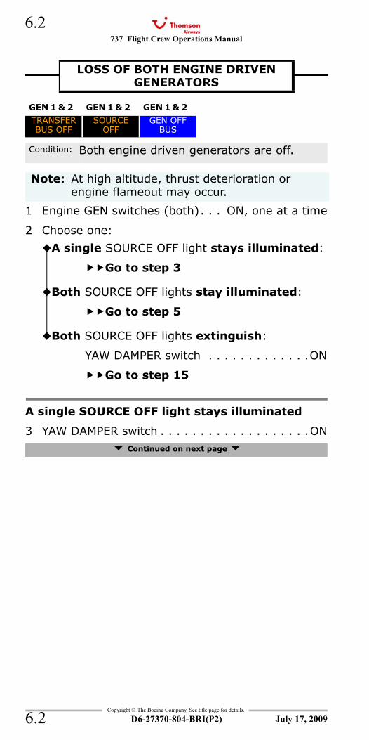
737 Flight Crew Operations Manual
Copyright © The Boeing Company. See title page for details.
D6-27370-804-BRI(P2)
6.2
6.2
SOURCE OFF (both)TRANSFER BUS OFF, SOURCE OFF and GEN OFF (both sides)SOURCE OFF, TRANSFER BUS OFF and GEN OFF BUS (both sides)GEN OFF BUS, SOURCE OFF and TRANSFER BUS OFF (both sides)
1 Engine GEN switches (both). . . ON, one at a time
2 Choose one:
A single SOURCE OFF light stays illuminated
3 YAW DAMPER switch . . . . . . . . . . . . . . . . . . .ON Continued on next page
LOSS OF BOTH ENGINE DRIVEN GENERATORS
GEN 1 & 2 GEN 1 & 2 GEN 1 & 2
TRANSFERBUS OFF
SOURCEOFF
GEN OFFBUS
Condition: Both engine driven generators are off.
Note: At high altitude, thrust deterioration or engine flameout may occur.
A single SOURCE OFF light stays illuminated:
Go to step 3
Both SOURCE OFF lights stay illuminated:
Go to step 5
Both SOURCE OFF lights extinguish:
YAW DAMPER switch . . . . . . . . . . . . .ON
Go to step 15
July 17, 2009
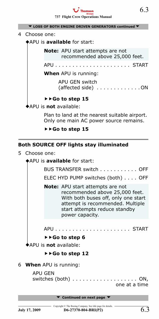
737 Flight Crew Operations Manual 6.3
Copyright © The Boeing Company. See title page for details.
D6-27370-804-BRI(P2) 6.3
4 Choose one:
Both SOURCE OFF lights stay illuminated
5 Choose one:
6 When APU is running:
APU GEN switches (both) . . . . . . . . . . . . . . . . . . . ON,
one at a time
Continued on next page
LOSS OF BOTH ENGINE DRIVEN GENERATORS continued
APU is available for start:
Note: APU start attempts are not recommended above 25,000 feet.
APU . . . . . . . . . . . . . . . . . . . . . . START
When APU is running:
APU GEN switch(affected side) . . . . . . . . . . . . .ON
Go to step 15
APU is not available:
Plan to land at the nearest suitable airport. Only one main AC power source remains.
Go to step 15
APU is available for start:
BUS TRANSFER switch . . . . . . . . . . . OFF
ELEC HYD PUMP switches (both) . . . . OFF
Note: APU start attempts are not recommended above 25,000 feet. With both buses off, only one start attempt is recommended. Multiple start attempts reduce standby power capacity.
APU . . . . . . . . . . . . . . . . . . . . . . START
Go to step 6
APU is not available:
Go to step 12
July 17, 2009
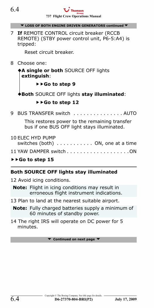
737 Flight Crew Operations Manual
Copyright © The Boeing Company. See title page for details.
D6-27370-804-BRI(P2)
6.4
6.4
7 If REMOTE CONTROL circuit breaker (RCCB REMOTE) (STBY power control unit, P6-5:A4) is tripped:
Reset circuit breaker.
8 Choose one:
9 BUS TRANSFER switch . . . . . . . . . . . . . . . AUTO
This restores power to the remaining transfer bus if one BUS OFF light stays illuminated.
10 ELEC HYD PUMPswitches (both) . . . . . . . . . . . ON, one at a time
11 YAW DAMPER switch . . . . . . . . . . . . . . . . . . .ON
Go to step 15
Both SOURCE OFF lights stay illuminated
12 Avoid icing conditions.
13 Plan to land at the nearest suitable airport.
14 The right IRS will operate on DC power for 5 minutes.
Continued on next page
LOSS OF BOTH ENGINE DRIVEN GENERATORS continued
A single or both SOURCE OFF lights extinguish:
Go to step 9
Both SOURCE OFF lights stay illuminated:
Go to step 12
Note: Flight in icing conditions may result in erroneous flight instrument indications.
Note: Fully charged batteries supply a minimum of 60 minutes of standby power.
July 17, 2009
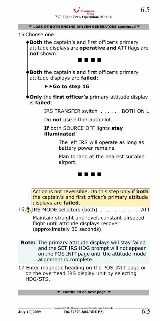
737 Flight Crew Operations Manual 6.5
Copyright © The Boeing Company. See title page for details.
D6-27370-804-BRI(P2) 6.5
15 Choose one:
Maintain straight and level, constant airspeed flight until attitude displays recover (approximately 30 seconds).
17 Enter magnetic heading on the POS INIT page or on the overhead IRS display unit by selecting HDG/STS.
Continued on next page
LOSS OF BOTH ENGINE DRIVEN GENERATORS continued
Both the captain’s and first officer’s primary attitude displays are operative and ATT flags are not shown:
Both the captain’s and first officer’s primary attitude displays are failed:
Go to step 16
Only the first officer’s primary attitude display is failed:
IRS TRANSFER switch . . . . . . BOTH ON L
Do not use either autopilot.
If both SOURCE OFF lights stay illuminated:
The left IRS will operate as long as battery power remains.
Plan to land at the nearest suitable airport.
Action is not reversible. Do this step only if both the captain’s and first officer’s primary attitude displays are failed.
16 IRS MODE selectors (both) . . . . . . . . . . . .ATT
Note: The primary attitude displays will stay failed and the SET IRS HDG prompt will not appear on the POS INIT page until the attitude mode alignment is complete.
July 17, 2009
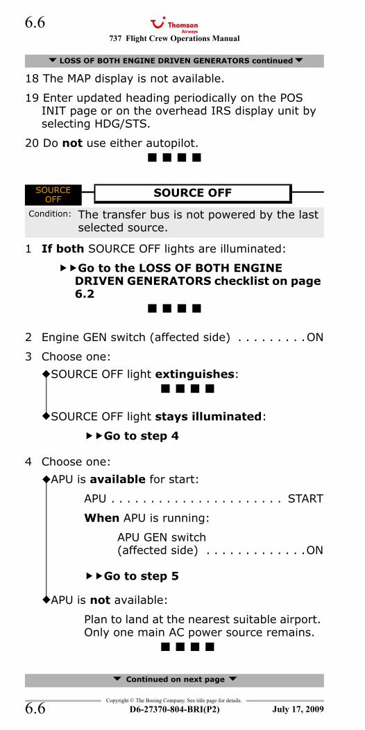
737 Flight Crew Operations Manual
Copyright © The Boeing Company. See title page for details.
D6-27370-804-BRI(P2)
6.6
6.6
18 The MAP display is not available.
19 Enter updated heading periodically on the POS INIT page or on the overhead IRS display unit by selecting HDG/STS.
20 Do not use either autopilot.
SOURCE OFF (single)
1 If both SOURCE OFF lights are illuminated:
Go to the LOSS OF BOTH ENGINE DRIVEN GENERATORS checklist on page 6.2
2 Engine GEN switch (affected side) . . . . . . . . .ON
3 Choose one:
4 Choose one:
Continued on next page
LOSS OF BOTH ENGINE DRIVEN GENERATORS continued
SOURCEOFF
SOURCE OFF
Condition: The transfer bus is not powered by the last selected source.
SOURCE OFF light extinguishes:
SOURCE OFF light stays illuminated:
Go to step 4
APU is available for start:
APU . . . . . . . . . . . . . . . . . . . . . . START
When APU is running:
APU GEN switch (affected side) . . . . . . . . . . . . .ON
Go to step 5
APU is not available:
Plan to land at the nearest suitable airport. Only one main AC power source remains.
July 17, 2009
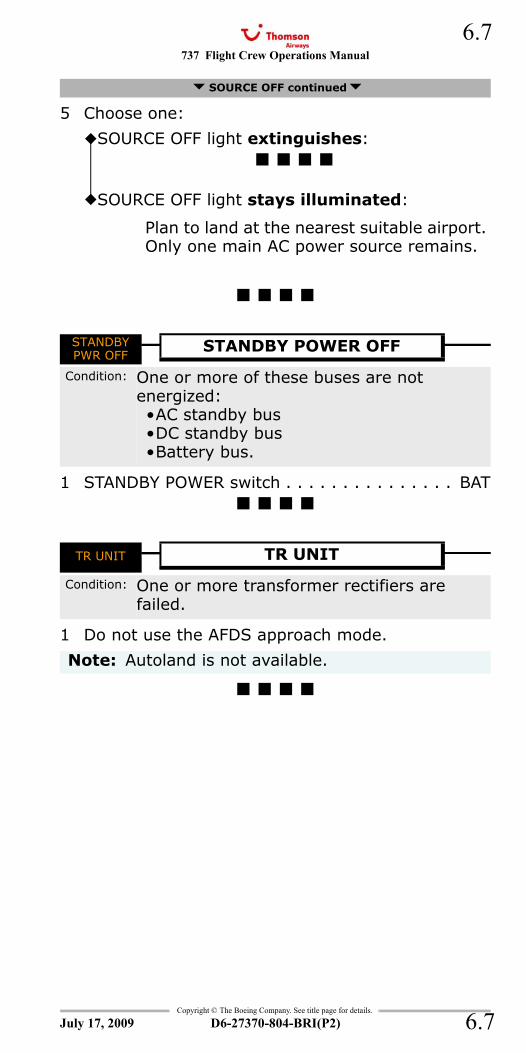
737 Flight Crew Operations Manual 6.7
Copyright © The Boeing Company. See title page for details.
D6-27370-804-BRI(P2) 6.7
5 Choose one:
STANDBY PWR OFF
1 STANDBY POWER switch . . . . . . . . . . . . . . . BAT
TR UNIT
1 Do not use the AFDS approach mode.
SOURCE OFF continued
SOURCE OFF light extinguishes:
SOURCE OFF light stays illuminated:
Plan to land at the nearest suitable airport. Only one main AC power source remains.
STANDBYPWR OFF
STANDBY POWER OFF
Condition: One or more of these buses are not energized:•AC standby bus•DC standby bus•Battery bus.
TR UNIT TR UNIT
Condition: One or more transformer rectifiers are failed.
Note: Autoland is not available.
July 17, 2009
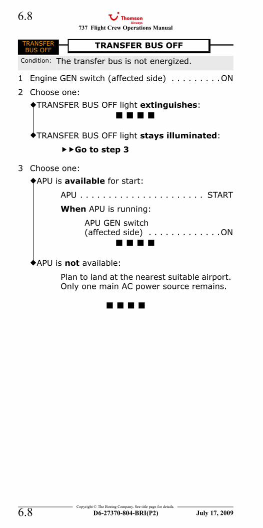
737 Flight Crew Operations Manual
Copyright © The Boeing Company. See title page for details.
D6-27370-804-BRI(P2)
6.8
6.8
TRANSFER BUS OFF
1 Engine GEN switch (affected side) . . . . . . . . .ON
2 Choose one:
3 Choose one:
TRANSFERBUS OFF
TRANSFER BUS OFF
Condition: The transfer bus is not energized.
TRANSFER BUS OFF light extinguishes:
TRANSFER BUS OFF light stays illuminated:
Go to step 3
APU is available for start:
APU . . . . . . . . . . . . . . . . . . . . . . START
When APU is running:
APU GEN switch (affected side) . . . . . . . . . . . . .ON
APU is not available:
Plan to land at the nearest suitable airport. Only one main AC power source remains.
July 17, 2009
737 Flight Crew Operations Manual
Non-Normal Checklists Chapter NNCEngines, APU Section 7
Table of Contents
Copyright © The Boeing Company. See title page for details.
D6-27370-804-BRI(P2) 7.TOC.1
Aborted Engine Start.....................................7.1APU FIRE ................................................ 8.1ENGINE FIRE or Engine Severe Damage or Separation .............................................. 8.2Engine Limit or Surge or Stall .......................7.2ENGINE OVERHEAT ................................. 8.4Engine Tailpipe Fire ................................ 8.6Loss Of Thrust On Both Engines ....................7.4
Aborted Engine Start.....................................7.1APU DETECTION INOPERATIVE .................. 8.10APU FAULT ......................................................7.8APU FIRE ................................................ 8.1APU LOW OIL PRESSURE...................................7.8APU OVERSPEED..............................................7.9EEC ALTERNATE MODE .....................................7.9ENGINE CONTROL ..........................................7.10Engine Failure or Shutdown .............................7.10ENGINE FIRE or Engine Severe Damage or Separation .............................................. 8.2ENGINE FIRE/OVERHEAT DETECTOR FAULT . 8.14Engine Fuel Leak...................................... 12.4Engine High Oil Temperature ...........................7.12Engine In-Flight Start .....................................7.13Engine Limit or Surge or Stall .......................7.2ENGINE LOW OIL PRESSURE ...........................7.15ENGINE OIL FILTER BYPASS ............................7.16ENGINE OVERHEAT ................................. 8.4Engine Tailpipe Fire ................................ 8.6High Engine Vibration .....................................7.17Loss Of Thrust On Both Engines ....................7.4One Engine Inoperative Landing <> .................7.18One Engine Inoperative Landing <> .................7.20REVERSER ....................................................7.23REVERSER UNLOCKED (IN FLIGHT) ..................7.24START VALVE OPEN........................................7.25
July 17, 2009
NNC.7-Engines, APUTable Of Contents
737 Flight Crew Operations Manual
Non-Normal Checklists -Engines, APU
Table of Contents
Copyright © The Boeing Company. See title page for details.
D6-27370-804-BRI(P2)7.TOC.2
Volcanic Ash ..................................................7.26
July 17, 2009
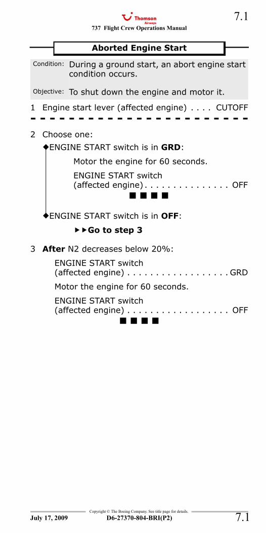
737 Flight Crew Operations Manual 7.1
Copyright © The Boeing Company. See title page for details.
D6-27370-804-BRI(P2) 7.1
NNC.7 Non-Normal Checklists-Engines, APU
1 Engine start lever (affected engine) . . . . CUTOFF- - - - - - - - - - - - - - - - - - - - - - -2 Choose one:
3 After N2 decreases below 20%:
ENGINE START switch (affected engine) . . . . . . . . . . . . . . . . . . GRD
Motor the engine for 60 seconds.
ENGINE START switch (affected engine) . . . . . . . . . . . . . . . . . . OFF
APU FIRE 8.1ENGINE FIRE or Engine Severe Damage or Separation 8.2
Aborted Engine Start
Condition: During a ground start, an abort engine start condition occurs.
Objective: To shut down the engine and motor it.
ENGINE START switch is in GRD:
Motor the engine for 60 seconds.
ENGINE START switch(affected engine) . . . . . . . . . . . . . . . OFF
ENGINE START switch is in OFF:
Go to step 3
July 17, 2009
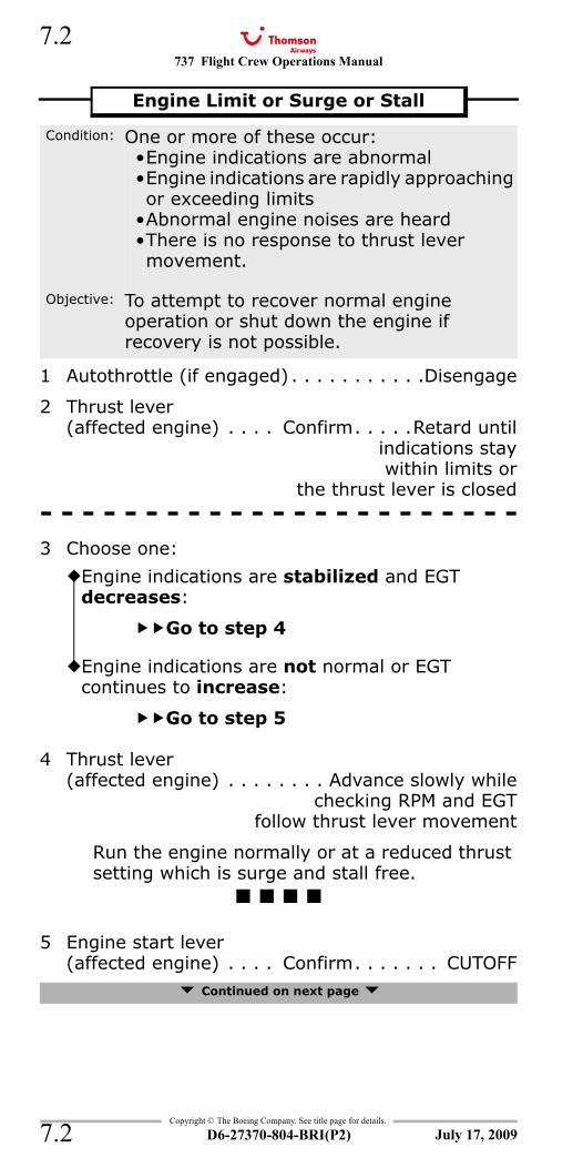
737 Flight Crew Operations Manual
Copyright © The Boeing Company. See title page for details.
D6-27370-804-BRI(P2)
7.2
7.2
1 Autothrottle (if engaged) . . . . . . . . . . .Disengage
2 Thrust lever (affected engine) . . . . Confirm. . . . .Retard until
indications staywithin limits or
the thrust lever is closed- - - - - - - - - - - - - - - - - - - - - - -3 Choose one:
4 Thrust lever(affected engine) . . . . . . . . Advance slowly while
checking RPM and EGTfollow thrust lever movement
Run the engine normally or at a reduced thrust setting which is surge and stall free.
5 Engine start lever (affected engine) . . . . Confirm. . . . . . . CUTOFF
Continued on next page
Engine Limit or Surge or Stall
Condition: One or more of these occur:•Engine indications are abnormal•Engine indications are rapidly approaching or exceeding limits
•Abnormal engine noises are heard•There is no response to thrust lever movement.
Objective: To attempt to recover normal engine operation or shut down the engine if recovery is not possible.
Engine indications are stabilized and EGT decreases:
Go to step 4
Engine indications are not normal or EGT continues to increase:
Go to step 5
July 17, 2009
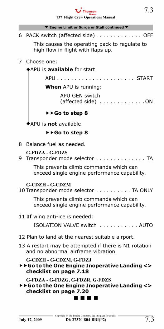
737 Flight Crew Operations Manual 7.3
Copyright © The Boeing Company. See title page for details.
D6-27370-804-BRI(P2) 7.3
6 PACK switch (affected side) . . . . . . . . . . . . . OFF
This causes the operating pack to regulate to high flow in flight with flaps up.
7 Choose one:
8 Balance fuel as needed.
G-FDZA - G-FDZS9 Transponder mode selector . . . . . . . . . . . . . . TA
This prevents climb commands which can exceed single engine performance capability.
G-CDZH - G-CDZM10 Transponder mode selector . . . . . . . . . . TA ONLY
This prevents climb commands which can exceed single engine performance capability.
11 If wing anti-ice is needed:
ISOLATION VALVE switch . . . . . . . . . . . AUTO
12 Plan to land at the nearest suitable airport.
13 A restart may be attempted if there is N1 rotation and no abnormal airframe vibration.
G-CDZH - G-CDZM, G-FDZJGo to the One Engine Inoperative Landing <> checklist on page 7.18
G-FDZA - G-FDZG, G-FDZR, G-FDZSGo to the One Engine Inoperative Landing <> checklist on page 7.20
ENGINE OVERHEAT 8.4Engine Tailpipe Fire 8.6
Engine Limit or Surge or Stall continued
APU is available for start:
APU . . . . . . . . . . . . . . . . . . . . . . START
When APU is running:
APU GEN switch(affected side) . . . . . . . . . . . . .ON
Go to step 8
APU is not available:
Go to step 8
July 17, 2009
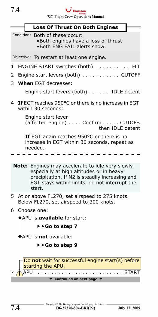
737 Flight Crew Operations Manual
Copyright © The Boeing Company. See title page for details.
D6-27370-804-BRI(P2)
7.4
7.4
ENG FAIL (both)
1 ENGINE START switches (both) . . . . . . . . . . FLT
2 Engine start levers (both) . . . . . . . . . . . CUTOFF
3 When EGT decreases:
Engine start levers (both) . . . . . . IDLE detent
4 If EGT reaches 950°C or there is no increase in EGT within 30 seconds:
Engine start lever (affected engine) . . . . Confirm . . . . . CUTOFF,
then IDLE detent
If EGT again reaches 950°C or there is no increase in EGT within 30 seconds, repeat as needed.
- - - - - - - - - - - - - - - - - - - - - - -
5 At or above FL270, set airspeed to 275 knots. Below FL270, set airspeed to 300 knots.
6 Choose one:
Continued on next page
Loss Of Thrust On Both EnginesCondition: Both of these occur:
•Both engines have a loss of thrust•Both ENG FAIL alerts show.
Objective: To restart at least one engine.
Note: Engines may accelerate to idle very slowly, especially at high altitudes or in heavy precipitation. If N2 is steadily increasing and EGT stays within limits, do not interrupt the start.
APU is available for start:
Go to step 7
APU is not available:
Go to step 9
Do not wait for successful engine start(s) before starting the APU.
7 APU . . . . . . . . . . . . . . . . . . . . . . . . . START
July 17, 2009
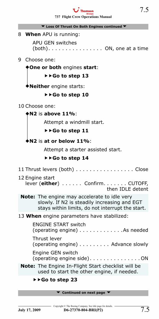
737 Flight Crew Operations Manual 7.5
Copyright © The Boeing Company. See title page for details.
D6-27370-804-BRI(P2) 7.5
8 When APU is running:
APU GEN switches (both). . . . . . . . . . . . . . . . ON, one at a time
9 Choose one:
10 Choose one:
11 Thrust levers (both) . . . . . . . . . . . . . . . . . Close
12 Engine start lever (either) . . . . . . Confirm. . . . . . . CUTOFF,
then IDLE detent
13 When engine parameters have stabilized:
ENGINE START switch(operating engine) . . . . . . . . . . . . .As needed
Thrust lever(operating engine) . . . . . . . . . Advance slowly
Engine GEN switch(operating engine side). . . . . . . . . . . . . . . ON
Go to step 23
Continued on next page
Loss Of Thrust On Both Engines continued
One or both engines start:
Go to step 13
Neither engine starts:
Go to step 10
N2 is above 11%:
Attempt a windmill start.
Go to step 11
N2 is at or below 11%:
Attempt a starter assisted start.
Go to step 14
Note: The engine may accelerate to idle very slowly. If N2 is steadily increasing and EGT stays within limits, do not interrupt the start.
Note: The Engine In-Flight Start checklist will be used to start the other engine, if needed.
July 17, 2009
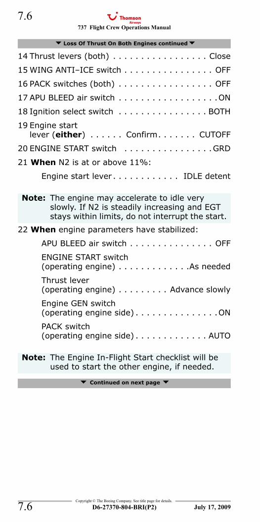
737 Flight Crew Operations Manual
Copyright © The Boeing Company. See title page for details.
D6-27370-804-BRI(P2)
7.6
7.6
14 Thrust levers (both) . . . . . . . . . . . . . . . . . Close
15 WING ANTI–ICE switch . . . . . . . . . . . . . . . . OFF
16 PACK switches (both) . . . . . . . . . . . . . . . . . OFF
17 APU BLEED air switch . . . . . . . . . . . . . . . . . .ON
18 Ignition select switch . . . . . . . . . . . . . . . . BOTH
19 Engine start lever (either) . . . . . . Confirm. . . . . . . CUTOFF
20 ENGINE START switch . . . . . . . . . . . . . . . .GRD
21 When N2 is at or above 11%:
Engine start lever . . . . . . . . . . . . IDLE detent
22 When engine parameters have stabilized:
APU BLEED air switch . . . . . . . . . . . . . . . OFF
ENGINE START switch(operating engine) . . . . . . . . . . . . .As needed
Thrust lever(operating engine) . . . . . . . . . Advance slowly
Engine GEN switch(operating engine side) . . . . . . . . . . . . . . .ON
PACK switch(operating engine side) . . . . . . . . . . . . . AUTO
Continued on next page
Loss Of Thrust On Both Engines continued
Note: The engine may accelerate to idle very slowly. If N2 is steadily increasing and EGT stays within limits, do not interrupt the start.
Note: The Engine In-Flight Start checklist will be used to start the other engine, if needed.
July 17, 2009
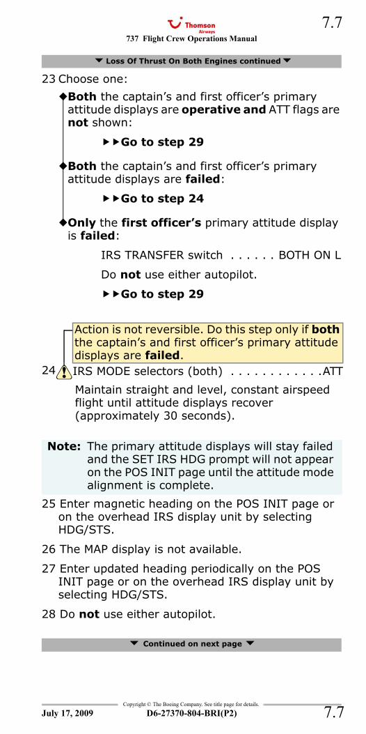
737 Flight Crew Operations Manual 7.7
Copyright © The Boeing Company. See title page for details.
D6-27370-804-BRI(P2) 7.7
23 Choose one:
Maintain straight and level, constant airspeed flight until attitude displays recover (approximately 30 seconds).
25 Enter magnetic heading on the POS INIT page or on the overhead IRS display unit by selecting HDG/STS.
26 The MAP display is not available.
27 Enter updated heading periodically on the POS INIT page or on the overhead IRS display unit by selecting HDG/STS.
28 Do not use either autopilot.
Continued on next page
Loss Of Thrust On Both Engines continued
Both the captain’s and first officer’s primary attitude displays are operative and ATT flags are not shown:
Go to step 29
Both the captain’s and first officer’s primary attitude displays are failed:
Go to step 24
Only the first officer’s primary attitude display is failed:
IRS TRANSFER switch . . . . . . BOTH ON L
Do not use either autopilot.
Go to step 29
Action is not reversible. Do this step only if both the captain’s and first officer’s primary attitude displays are failed.
24 IRS MODE selectors (both) . . . . . . . . . . . .ATT
Note: The primary attitude displays will stay failed and the SET IRS HDG prompt will not appear on the POS INIT page until the attitude mode alignment is complete.
July 17, 2009
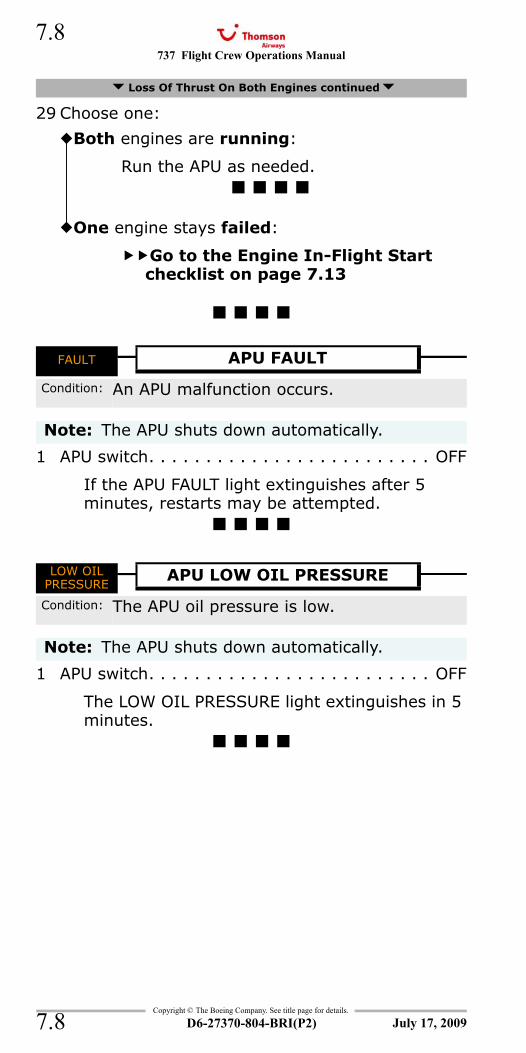
737 Flight Crew Operations Manual
Copyright © The Boeing Company. See title page for details.
D6-27370-804-BRI(P2)
7.8
7.8
29 Choose one:
APU DETECTION INOPERATIVE 8.10FAULT - APU
1 APU switch. . . . . . . . . . . . . . . . . . . . . . . . . OFF
If the APU FAULT light extinguishes after 5 minutes, restarts may be attempted.
LOW OIL PRESSURE - APU
1 APU switch. . . . . . . . . . . . . . . . . . . . . . . . . OFF
The LOW OIL PRESSURE light extinguishes in 5 minutes.
Loss Of Thrust On Both Engines continued
Both engines are running:
Run the APU as needed.
One engine stays failed:
Go to the Engine In-Flight Start checklist on page 7.13
FAULT APU FAULT
Condition: An APU malfunction occurs.
Note: The APU shuts down automatically.
LOW OILPRESSURE
APU LOW OIL PRESSURE
Condition: The APU oil pressure is low.
Note: The APU shuts down automatically.
July 17, 2009
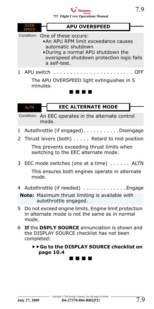
737 Flight Crew Operations Manual 7.9
Copyright © The Boeing Company. See title page for details.
D6-27370-804-BRI(P2) 7.9
OVER SPEED - APU
1 APU switch . . . . . . . . . . . . . . . . . . . . . . . . OFF
The APU OVERSPEED light extinguishes in 5 minutes.
ALTN - EEC
1 Autothrottle (if engaged). . . . . . . . . . .Disengage
2 Thrust levers (both) . . . . . Retard to mid position
This prevents exceeding thrust limits when switching to the EEC alternate mode.
3 EEC mode switches (one at a time) . . . . . . ALTN
This ensures both engines operate in alternate mode.
4 Autothrottle (if needed) . . . . . . . . . . . . . Engage
5 Do not exceed engine limits. Engine limit protection in alternate mode is not the same as in normal mode.
6 If the DSPLY SOURCE annunciation is shown and the DISPLAY SOURCE checklist has not been completed:
Go to the DISPLAY SOURCE checklist on page 10.4
OVERSPEED
APU OVERSPEED
Condition: One of these occurs:•An APU RPM limit exceedance causes automatic shutdown
•During a normal APU shutdown the overspeed shutdown protection logic fails a self-test.
ALTN EEC ALTERNATE MODE
Condition: An EEC operates in the alternate control mode.
Note: Maximum thrust limiting is available with autothrottle engaged.
July 17, 2009
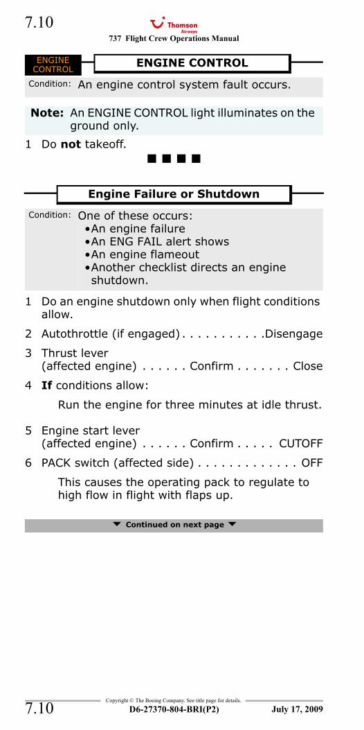
737 Flight Crew Operations Manual
Copyright © The Boeing Company. See title page for details.
D6-27370-804-BRI(P2)
7.10
7.10
ENGINE CONTROL
1 Do not takeoff.
ENG FAIL (single)
1 Do an engine shutdown only when flight conditions allow.
2 Autothrottle (if engaged) . . . . . . . . . . .Disengage
3 Thrust lever (affected engine) . . . . . . Confirm . . . . . . . Close
4 If conditions allow:
Run the engine for three minutes at idle thrust.
5 Engine start lever (affected engine) . . . . . . Confirm . . . . . CUTOFF
6 PACK switch (affected side) . . . . . . . . . . . . . OFF
This causes the operating pack to regulate to high flow in flight with flaps up.
Continued on next page
ENGINECONTROL
ENGINE CONTROL
Condition: An engine control system fault occurs.
Note: An ENGINE CONTROL light illuminates on the ground only.
Engine Failure or Shutdown
Condition: One of these occurs:•An engine failure•An ENG FAIL alert shows•An engine flameout•Another checklist directs an engine shutdown.
July 17, 2009
737 Flight Crew Operations Manual 7.11
Copyright © The Boeing Company. See title page for details.
D6-27370-804-BRI(P2) 7.11
7 Choose one:
8 Balance fuel as needed.
G-FDZA - G-FDZS9 Transponder mode selector . . . . . . . . . . . . . . TA
This prevents climb commands which can exceed single engine performance capability.
G-CDZH - G-CDZM10 Transponder mode selector . . . . . . . . . . TA ONLY
This prevents climb commands which can exceed single engine performance capability.
11 If wing anti–ice is needed:
ISOLATION VALVE switch . . . . . . . . . . . AUTO
12 Plan to land at the nearest suitable airport.
G-CDZH - G-CDZM, G-FDZJGo to the One Engine Inoperative Landing <> checklist on page 7.18
G-FDZA - G-FDZG, G-FDZR, G-FDZSGo to the One Engine Inoperative Landing <> checklist on page 7.20
ENGINE FIRE/OVERHEAT DETECTOR FAULT 8.14Engine Fuel Leak 12.4
Engine Failure or Shutdown continued
APU is available for start:
APU . . . . . . . . . . . . . . . . . . . . . . START
When APU is running:
APU GEN switch(affected side) . . . . . . . . . . . . .ON
Go to step 8
APU is not available:
Go to step 8
July 17, 2009
737 Flight Crew Operations Manual
Copyright © The Boeing Company. See title page for details.
D6-27370-804-BRI(P2)
7.12
7.12
1 Choose one:
2 Autothrottle (if engaged) . . . . . . . . . . .Disengage
3 Thrust lever(affected engine) . . . . Confirm. . . Retard slowly
until engine oil temperature iswithin normal operating range
or thrust lever is closed
4 If temperature is in the amber band for more than 45 minutes:
Go to the Engine Failure or Shutdown checklist on page 7.10
Engine High Oil Temperature
Condition: The engine oil temperature is high.
Temperature is at or above the redline:
Go to the Engine Failure or Shutdown checklist on page 7.10
Temperature is in the amber band:
Go to step 2
July 17, 2009
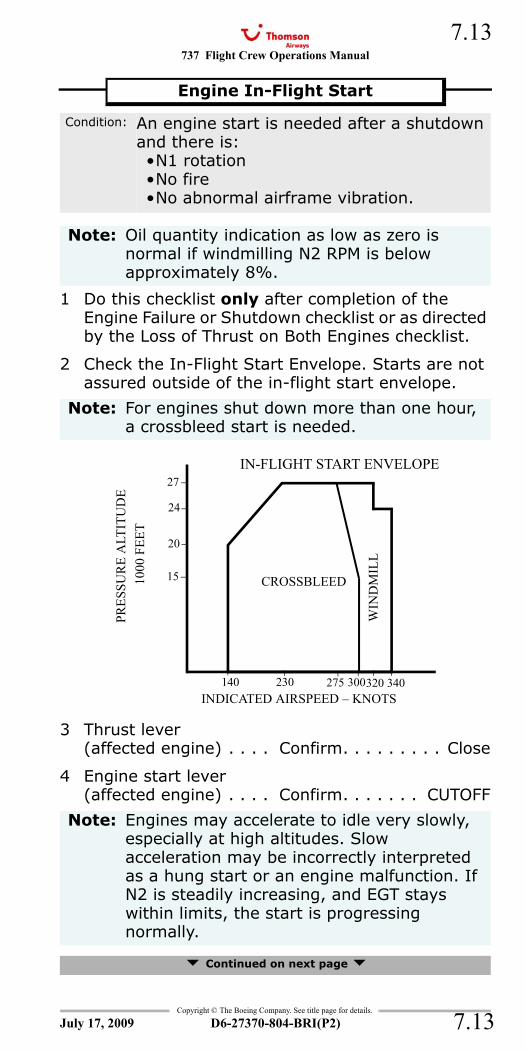
737 Flight Crew Operations Manual 7.13
Copyright © The Boeing Company. See title page for details.
D6-27370-804-BRI(P2) 7.13
1 Do this checklist only after completion of the Engine Failure or Shutdown checklist or as directed by the Loss of Thrust on Both Engines checklist.
2 Check the In-Flight Start Envelope. Starts are not assured outside of the in-flight start envelope.
3 Thrust lever (affected engine) . . . . Confirm. . . . . . . . . Close
4 Engine start lever (affected engine) . . . . Confirm. . . . . . . CUTOFF
Continued on next page
Engine In-Flight Start
Condition: An engine start is needed after a shutdown and there is:•N1 rotation•No fire•No abnormal airframe vibration.
Note: Oil quantity indication as low as zero is normal if windmilling N2 RPM is below approximately 8%.
Note: For engines shut down more than one hour, a crossbleed start is needed.
Note: Engines may accelerate to idle very slowly, especially at high altitudes. Slow acceleration may be incorrectly interpreted as a hung start or an engine malfunction. If N2 is steadily increasing, and EGT stays within limits, the start is progressing normally.
24
27
20
140 230 320 340INDICATED AIRSPEED – KNOTS
300
15
275
WIN
DM
ILL
CROSSBLEED
IN-FLIGHT START ENVELOPE
PRES
SUR
E A
LTIT
UD
E 10
00 F
EET
July 17, 2009
737 Flight Crew Operations Manual
Copyright © The Boeing Company. See title page for details.
D6-27370-804-BRI(P2)
7.14
7.14
5 Choose one:
6 When N2 is at or above 11%:
Engine start lever (affected engine) . . . . . . . . . . . . IDLE detent
Monitor EGT to ensure it does not rise rapidly or exceed the start limit of 725° C during the start attempt.
7 If EGT does not increase in 30 seconds or another abort start condition as listed in the Normal Procedures occurs:
Engine start lever(affected engine) . . . . Confirm . . . . . CUTOFF
ENGINE START switch(affected engine) . . . . . . . . . . . . . . . . . . OFF
Continued on next page
Engine In-Flight Start continued
Windmill start:
ENGINE START switch (affected engine) . . . . . . . . . . . . . . . FLT
Go to step 6
Crossbleed start:
PACK switch (affected side). . . . . . . . OFF
DUCT PRESSURE . . . . . . Minimum 30 PSI
Advance the thrust lever to increase duct pressure if needed.
ENGINE START switch(affected engine) . . . . . . . . . . . . . . .GRD
Go to step 6
Note: If engine has been shutdown for more than 1 hour, multiple start attempts may be needed.
July 17, 2009
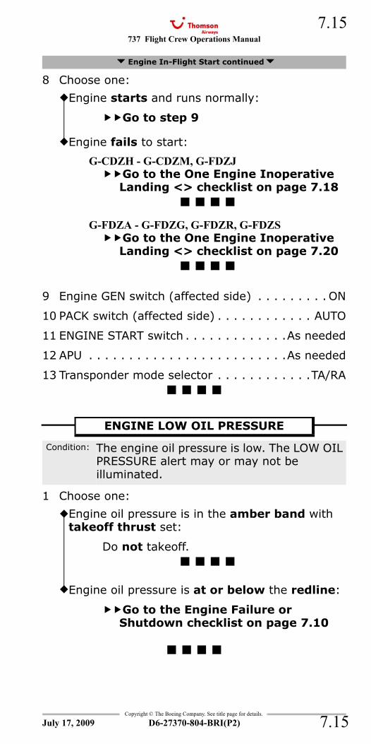
737 Flight Crew Operations Manual 7.15
Copyright © The Boeing Company. See title page for details.
D6-27370-804-BRI(P2) 7.15
8 Choose one:
9 Engine GEN switch (affected side) . . . . . . . . . ON
10 PACK switch (affected side) . . . . . . . . . . . . AUTO
11 ENGINE START switch . . . . . . . . . . . . .As needed
12 APU . . . . . . . . . . . . . . . . . . . . . . . . .As needed
13 Transponder mode selector . . . . . . . . . . . .TA/RA
LOW OIL PRESSURE - Engine
1 Choose one:
Engine In-Flight Start continued
Engine starts and runs normally:
Go to step 9
Engine fails to start:
G-CDZH - G-CDZM, G-FDZJGo to the One Engine Inoperative Landing <> checklist on page 7.18
G-FDZA - G-FDZG, G-FDZR, G-FDZSGo to the One Engine Inoperative Landing <> checklist on page 7.20
ENGINE LOW OIL PRESSURE
Condition: The engine oil pressure is low. The LOW OIL PRESSURE alert may or may not be illuminated.
Engine oil pressure is in the amber band with takeoff thrust set:
Do not takeoff.
Engine oil pressure is at or below the redline:
Go to the Engine Failure or Shutdown checklist on page 7.10
July 17, 2009
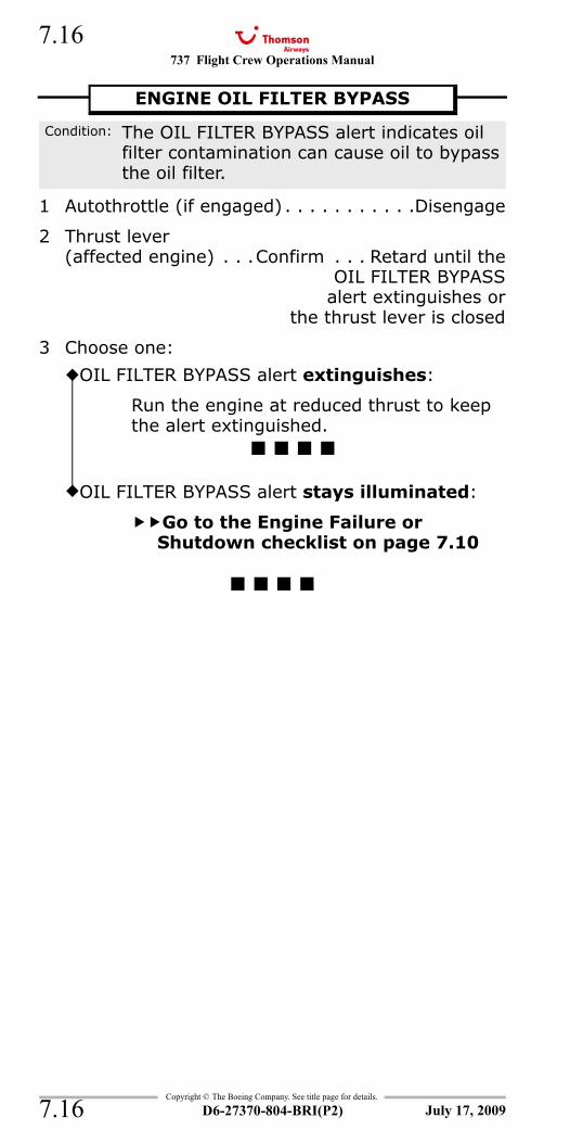
737 Flight Crew Operations Manual
Copyright © The Boeing Company. See title page for details.
D6-27370-804-BRI(P2)
7.16
7.16
OIL FILTER BYPASS
1 Autothrottle (if engaged) . . . . . . . . . . .Disengage
2 Thrust lever (affected engine) . . .Confirm . . . Retard until the
OIL FILTER BYPASSalert extinguishes or
the thrust lever is closed
3 Choose one:
ENGINE OIL FILTER BYPASS
Condition: The OIL FILTER BYPASS alert indicates oil filter contamination can cause oil to bypass the oil filter.
OIL FILTER BYPASS alert extinguishes:
Run the engine at reduced thrust to keep the alert extinguished.
OIL FILTER BYPASS alert stays illuminated:
Go to the Engine Failure or Shutdown checklist on page 7.10
July 17, 2009
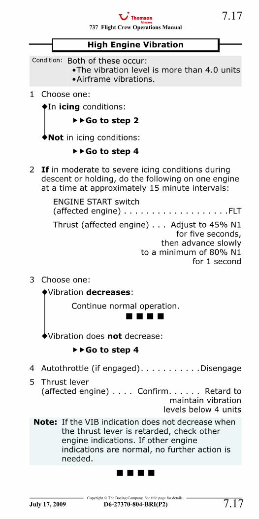
737 Flight Crew Operations Manual 7.17
Copyright © The Boeing Company. See title page for details.
D6-27370-804-BRI(P2) 7.17
1 Choose one:
2 If in moderate to severe icing conditions during descent or holding, do the following on one engine at a time at approximately 15 minute intervals:
ENGINE START switch(affected engine) . . . . . . . . . . . . . . . . . . .FLT
Thrust (affected engine) . . . Adjust to 45% N1for five seconds,
then advance slowlyto a minimum of 80% N1
for 1 second
3 Choose one:
4 Autothrottle (if engaged). . . . . . . . . . .Disengage
5 Thrust lever (affected engine) . . . . Confirm. . . . . . Retard to
maintain vibrationlevels below 4 units
High Engine Vibration
Condition: Both of these occur:•The vibration level is more than 4.0 units•Airframe vibrations.
In icing conditions:
Go to step 2
Not in icing conditions:
Go to step 4
Vibration decreases:
Continue normal operation.
Vibration does not decrease:
Go to step 4
Note: If the VIB indication does not decrease when the thrust lever is retarded, check other engine indications. If other engine indications are normal, no further action is needed.
July 17, 2009
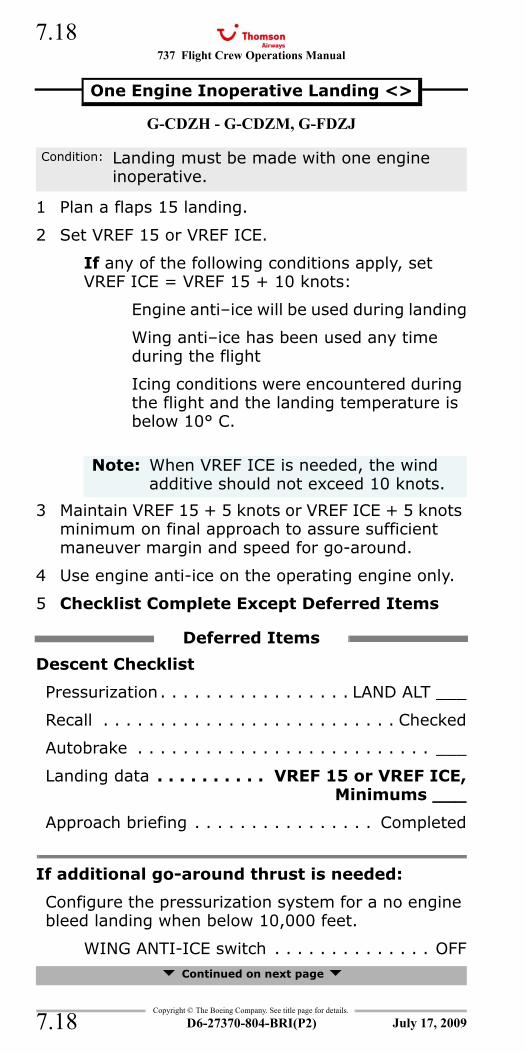
737 Flight Crew Operations Manual
Copyright © The Boeing Company. See title page for details.
D6-27370-804-BRI(P2)
7.18
7.18
G-CDZH - G-CDZM, G-FDZJ
1 Plan a flaps 15 landing.
2 Set VREF 15 or VREF ICE.
If any of the following conditions apply, set VREF ICE = VREF 15 + 10 knots:
Engine anti–ice will be used during landing
Wing anti–ice has been used any time during the flight
Icing conditions were encountered during the flight and the landing temperature is below 10° C.
3 Maintain VREF 15 + 5 knots or VREF ICE + 5 knots minimum on final approach to assure sufficient maneuver margin and speed for go-around.
4 Use engine anti-ice on the operating engine only.
5 Checklist Complete Except Deferred Items
Descent Checklist
Pressurization. . . . . . . . . . . . . . . . . LAND ALT ___
Recall . . . . . . . . . . . . . . . . . . . . . . . . . . Checked
Autobrake . . . . . . . . . . . . . . . . . . . . . . . . . . ___
Landing data . . . . . . . . . . VREF 15 or VREF ICE,Minimums ___
Approach briefing . . . . . . . . . . . . . . . . Completed
If additional go-around thrust is needed:
Configure the pressurization system for a no engine bleed landing when below 10,000 feet.
WING ANTI-ICE switch . . . . . . . . . . . . . . OFF Continued on next page
One Engine Inoperative Landing <>
Condition: Landing must be made with one engine inoperative.
Note: When VREF ICE is needed, the wind additive should not exceed 10 knots.
Deferred Items
July 17, 2009
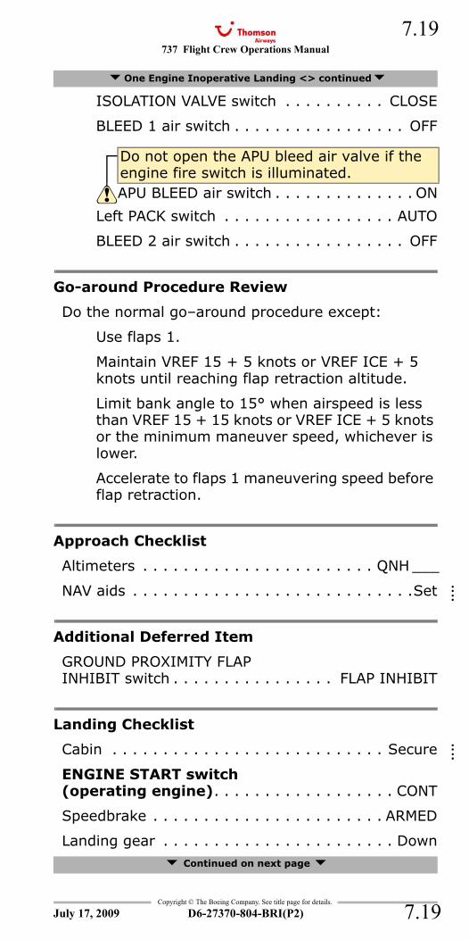
737 Flight Crew Operations Manual 7.19
Copyright © The Boeing Company. See title page for details.
D6-27370-804-BRI(P2) 7.19
ISOLATION VALVE switch . . . . . . . . . . CLOSE
BLEED 1 air switch . . . . . . . . . . . . . . . . . OFF
Left PACK switch . . . . . . . . . . . . . . . . . AUTO
BLEED 2 air switch . . . . . . . . . . . . . . . . . OFF
Go-around Procedure Review
Do the normal go–around procedure except:
Use flaps 1.
Maintain VREF 15 + 5 knots or VREF ICE + 5 knots until reaching flap retraction altitude.
Limit bank angle to 15° when airspeed is less than VREF 15 + 15 knots or VREF ICE + 5 knots or the minimum maneuver speed, whichever is lower.
Accelerate to flaps 1 maneuvering speed before flap retraction.
Approach Checklist
Altimeters . . . . . . . . . . . . . . . . . . . . . . . QNH ___
NAV aids . . . . . . . . . . . . . . . . . . . . . . . . . . . .Set
Additional Deferred Item
GROUND PROXIMITY FLAPINHIBIT switch . . . . . . . . . . . . . . . . FLAP INHIBIT
Landing Checklist
Cabin . . . . . . . . . . . . . . . . . . . . . . . . . . . Secure
ENGINE START switch(operating engine). . . . . . . . . . . . . . . . . . CONT
Speedbrake . . . . . . . . . . . . . . . . . . . . . . . ARMED
Landing gear . . . . . . . . . . . . . . . . . . . . . . . Down Continued on next page
One Engine Inoperative Landing <> continued
Do not open the APU bleed air valve if the engine fire switch is illuminated.APU BLEED air switch . . . . . . . . . . . . . . ON
July 17, 2009
::::
::::
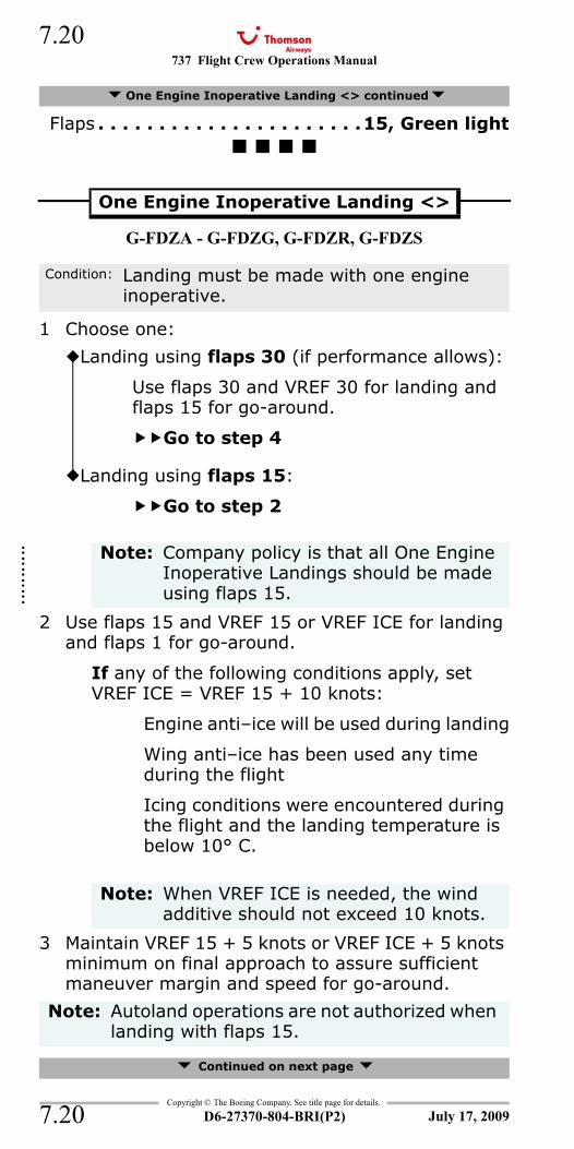
737 Flight Crew Operations Manual
Copyright © The Boeing Company. See title page for details.
D6-27370-804-BRI(P2)
7.20
7.20
Flaps . . . . . . . . . . . . . . . . . . . . . .15, Green light
G-FDZA - G-FDZG, G-FDZR, G-FDZS
1 Choose one:
2 Use flaps 15 and VREF 15 or VREF ICE for landing and flaps 1 for go-around.
If any of the following conditions apply, set VREF ICE = VREF 15 + 10 knots:
Engine anti–ice will be used during landing
Wing anti–ice has been used any time during the flight
Icing conditions were encountered during the flight and the landing temperature is below 10° C.
3 Maintain VREF 15 + 5 knots or VREF ICE + 5 knots minimum on final approach to assure sufficient maneuver margin and speed for go-around.
Continued on next page
One Engine Inoperative Landing <> continued
One Engine Inoperative Landing <>
Condition: Landing must be made with one engine inoperative.
Landing using flaps 30 (if performance allows):
Use flaps 30 and VREF 30 for landing and flaps 15 for go-around.
Go to step 4
Landing using flaps 15:
Go to step 2
Note: Company policy is that all One Engine Inoperative Landings should be made using flaps 15.
Note: When VREF ICE is needed, the wind additive should not exceed 10 knots.
Note: Autoland operations are not authorized when landing with flaps 15.
July 17, 2009
::::::
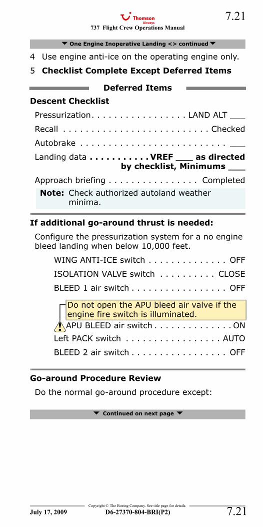
737 Flight Crew Operations Manual 7.21
Copyright © The Boeing Company. See title page for details.
D6-27370-804-BRI(P2) 7.21
4 Use engine anti-ice on the operating engine only.
5 Checklist Complete Except Deferred Items
Descent Checklist
Pressurization. . . . . . . . . . . . . . . . . LAND ALT ___
Recall . . . . . . . . . . . . . . . . . . . . . . . . . . Checked
Autobrake . . . . . . . . . . . . . . . . . . . . . . . . . . ___
Landing data . . . . . . . . . . . VREF ___ as directedby checklist, Minimums ___
Approach briefing . . . . . . . . . . . . . . . . Completed
If additional go-around thrust is needed:
Configure the pressurization system for a no engine bleed landing when below 10,000 feet.
WING ANTI-ICE switch . . . . . . . . . . . . . . OFF
ISOLATION VALVE switch . . . . . . . . . . CLOSE
BLEED 1 air switch . . . . . . . . . . . . . . . . . OFF
Left PACK switch . . . . . . . . . . . . . . . . . AUTO
BLEED 2 air switch . . . . . . . . . . . . . . . . . OFF
Go-around Procedure Review
Do the normal go-around procedure except:
Continued on next page
One Engine Inoperative Landing <> continued
Deferred Items
Note: Check authorized autoland weather minima.
Do not open the APU bleed air valve if the engine fire switch is illuminated.APU BLEED air switch . . . . . . . . . . . . . . ON
July 17, 2009
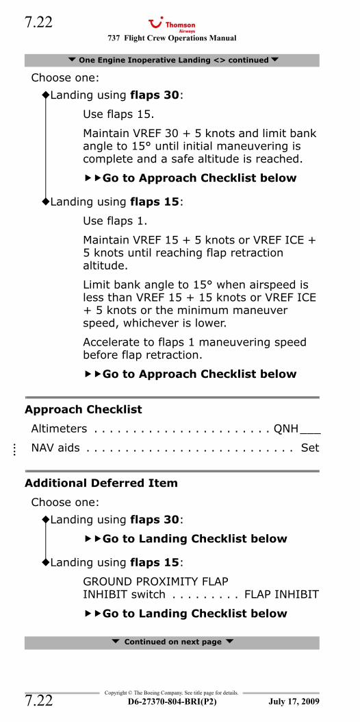
737 Flight Crew Operations Manual
Copyright © The Boeing Company. See title page for details.
D6-27370-804-BRI(P2)
7.22
7.22
Choose one:
Approach Checklist
Altimeters . . . . . . . . . . . . . . . . . . . . . . . QNH___
NAV aids . . . . . . . . . . . . . . . . . . . . . . . . . . . Set
Additional Deferred Item
Choose one:
Continued on next page
One Engine Inoperative Landing <> continued
Landing using flaps 30:
Use flaps 15.
Maintain VREF 30 + 5 knots and limit bank angle to 15° until initial maneuvering is complete and a safe altitude is reached.
Go to Approach Checklist below
Landing using flaps 15:
Use flaps 1.
Maintain VREF 15 + 5 knots or VREF ICE + 5 knots until reaching flap retraction altitude.
Limit bank angle to 15° when airspeed is less than VREF 15 + 15 knots or VREF ICE + 5 knots or the minimum maneuver speed, whichever is lower.
Accelerate to flaps 1 maneuvering speed before flap retraction.
Go to Approach Checklist below
Landing using flaps 30:
Go to Landing Checklist below
Landing using flaps 15:
GROUND PROXIMITY FLAPINHIBIT switch . . . . . . . . . FLAP INHIBIT
Go to Landing Checklist below
July 17, 2009
::::
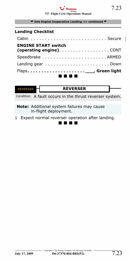
737 Flight Crew Operations Manual 7.23
Copyright © The Boeing Company. See title page for details.
D6-27370-804-BRI(P2) 7.23
Landing Checklist
Cabin . . . . . . . . . . . . . . . . . . . . . . . . . . . Secure
ENGINE START switch(operating engine). . . . . . . . . . . . . . . . . . CONT
Speedbrake . . . . . . . . . . . . . . . . . . . . . . . ARMED
Landing gear . . . . . . . . . . . . . . . . . . . . . . . Down
Flaps. . . . . . . . . . . . . . . . . . . . . ___, Green light
REVERSER
1 Expect normal reverser operation after landing.
One Engine Inoperative Landing <> continued
REVERSER REVERSER
Condition: A fault occurs in the thrust reverser system.
Note: Additional system failures may cause in-flight deployment.
July 17, 2009
::::
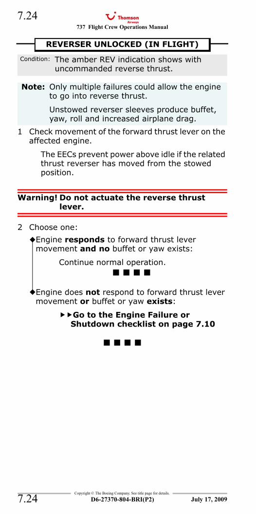
737 Flight Crew Operations Manual
Copyright © The Boeing Company. See title page for details.
D6-27370-804-BRI(P2)
7.24
7.24
REV
1 Check movement of the forward thrust lever on the affected engine.
The EECs prevent power above idle if the related thrust reverser has moved from the stowed position.
Warning! Do not actuate the reverse thrust lever.
2 Choose one:
REVERSER UNLOCKED (IN FLIGHT)
Condition: The amber REV indication shows with uncommanded reverse thrust.
Note: Only multiple failures could allow the engine to go into reverse thrust.
Unstowed reverser sleeves produce buffet, yaw, roll and increased airplane drag.
Engine responds to forward thrust lever movement and no buffet or yaw exists:
Continue normal operation.
Engine does not respond to forward thrust lever movement or buffet or yaw exists:
Go to the Engine Failure or Shutdown checklist on page 7.10
July 17, 2009
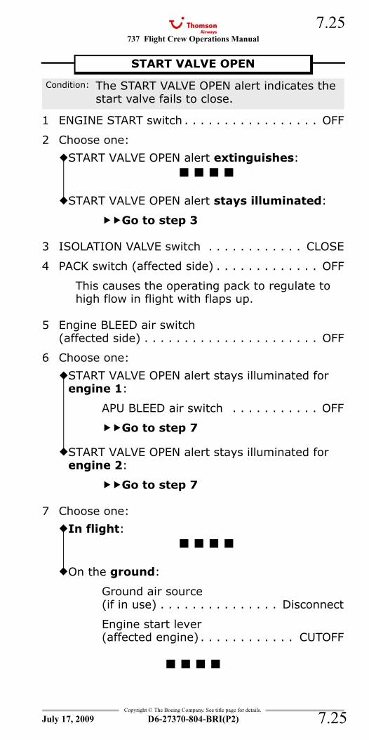
737 Flight Crew Operations Manual 7.25
Copyright © The Boeing Company. See title page for details.
D6-27370-804-BRI(P2) 7.25
START VALVE OPEN
1 ENGINE START switch . . . . . . . . . . . . . . . . . OFF
2 Choose one:
3 ISOLATION VALVE switch . . . . . . . . . . . . CLOSE
4 PACK switch (affected side) . . . . . . . . . . . . . OFF
This causes the operating pack to regulate to high flow in flight with flaps up.
5 Engine BLEED air switch(affected side) . . . . . . . . . . . . . . . . . . . . . . OFF
6 Choose one:
7 Choose one:
START VALVE OPEN
Condition: The START VALVE OPEN alert indicates the start valve fails to close.
START VALVE OPEN alert extinguishes:
START VALVE OPEN alert stays illuminated:
Go to step 3
START VALVE OPEN alert stays illuminated for engine 1:
APU BLEED air switch . . . . . . . . . . . OFF
Go to step 7
START VALVE OPEN alert stays illuminated for engine 2:
Go to step 7
In flight:
On the ground:
Ground air source (if in use) . . . . . . . . . . . . . . . Disconnect
Engine start lever (affected engine) . . . . . . . . . . . . CUTOFF
July 17, 2009
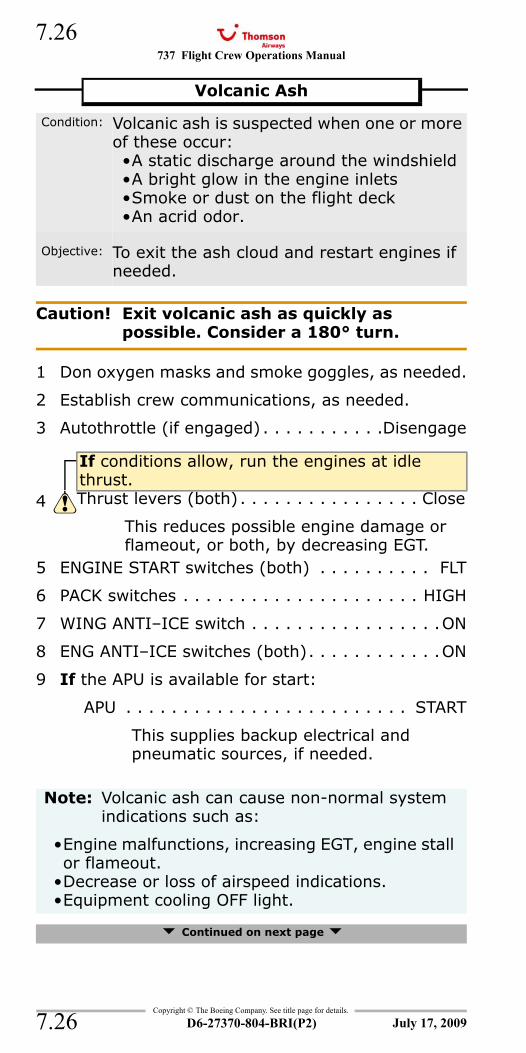
737 Flight Crew Operations Manual
Copyright © The Boeing Company. See title page for details.
D6-27370-804-BRI(P2)
7.26
7.26
Caution! Exit volcanic ash as quickly as possible. Consider a 180° turn.
1 Don oxygen masks and smoke goggles, as needed.
2 Establish crew communications, as needed.
3 Autothrottle (if engaged) . . . . . . . . . . .Disengage
5 ENGINE START switches (both) . . . . . . . . . . FLT
6 PACK switches . . . . . . . . . . . . . . . . . . . . . HIGH
7 WING ANTI–ICE switch . . . . . . . . . . . . . . . . .ON
8 ENG ANTI–ICE switches (both). . . . . . . . . . . .ON
9 If the APU is available for start:
APU . . . . . . . . . . . . . . . . . . . . . . . . . START
This supplies backup electrical and pneumatic sources, if needed.
Continued on next page
Volcanic Ash
Condition: Volcanic ash is suspected when one or more of these occur:•A static discharge around the windshield•A bright glow in the engine inlets•Smoke or dust on the flight deck•An acrid odor.
Objective: To exit the ash cloud and restart engines if needed.
If conditions allow, run the engines at idle thrust.
4 Thrust levers (both) . . . . . . . . . . . . . . . . Close
This reduces possible engine damage or flameout, or both, by decreasing EGT.
Note: Volcanic ash can cause non-normal system indications such as:
•Engine malfunctions, increasing EGT, engine stall or flameout.
•Decrease or loss of airspeed indications.•Equipment cooling OFF light.
July 17, 2009
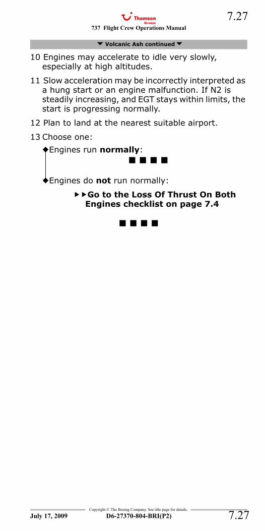
737 Flight Crew Operations Manual 7.27
Copyright © The Boeing Company. See title page for details.
D6-27370-804-BRI(P2) 7.27
10 Engines may accelerate to idle very slowly, especially at high altitudes.
11 Slow acceleration may be incorrectly interpreted as a hung start or an engine malfunction. If N2 is steadily increasing, and EGT stays within limits, the start is progressing normally.
12 Plan to land at the nearest suitable airport.
13 Choose one:
Volcanic Ash continued
Engines run normally:
Engines do not run normally:
Go to the Loss Of Thrust On Both Engines checklist on page 7.4
July 17, 2009
737 Flight Crew Operations Manual
Copyright © The Boeing Company. See title page for details.
D6-27370-804-BRI(P2)
7.28
7.28
IntentionallyBlank
July 17, 2009
737 Flight Crew Operations Manual
Non-Normal Checklists Chapter NNCFire Protection Section 8
Table of Contents
Copyright © The Boeing Company. See title page for details.
D6-27370-804-BRI(P2) 8.TOC.1
APU FIRE ......................................................8.1ENGINE FIRE or Engine Severe Damage or
Separation.................................................8.2ENGINE OVERHEAT .......................................8.4Engine Tailpipe Fire ......................................8.6
Smoke, Fire or Fumes ....................8.8
APU DETECTION INOPERATIVE ........................8.10APU FIRE ......................................................8.1CARGO FIRE < > ...........................................8.12CARGO FIRE DETECTOR FAULT ........................8.13ENGINE FIRE or Engine Severe Damage or
Separation.................................................8.2ENGINE FIRE/OVERHEAT DETECTOR FAULT .......8.14ENGINE OVERHEAT .......................................8.4Engine Tailpipe Fire ......................................8.6Smoke or Fumes Removal ...............................8.16
Smoke, Fire or Fumes ....................8.8WHEEL WELL FIRE..........................................8.18
July 17, 2009
NNC.8-Fire ProtectionTable Of Contents

737 Flight Crew Operations Manual
Non-Normal Checklists -Fire Protection
Table of Contents
Copyright © The Boeing Company. See title page for details.
D6-27370-804-BRI(P2)8.TOC.2
IntentionallyBlank
July 17, 2009
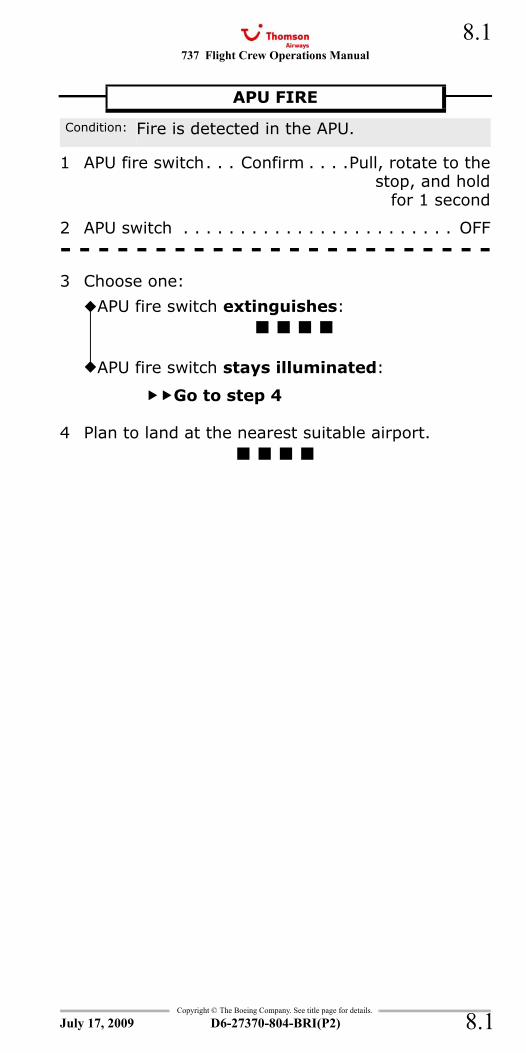
737 Flight Crew Operations Manual 8.1
Copyright © The Boeing Company. See title page for details.
D6-27370-804-BRI(P2) 8.1
NNC.8 Non-Normal Checklists-Fire ProtectionFIRE WARN and APU - FireAPU - Fire and FIRE WARN
1 APU fire switch. . . Confirm . . . .Pull, rotate to thestop, and hold
for 1 second
2 APU switch . . . . . . . . . . . . . . . . . . . . . . . . OFF- - - - - - - - - - - - - - - - - - - - - - -3 Choose one:
4 Plan to land at the nearest suitable airport.
APU FIRE
Condition: Fire is detected in the APU.
APU fire switch extinguishes:
APU fire switch stays illuminated:
Go to step 4
July 17, 2009
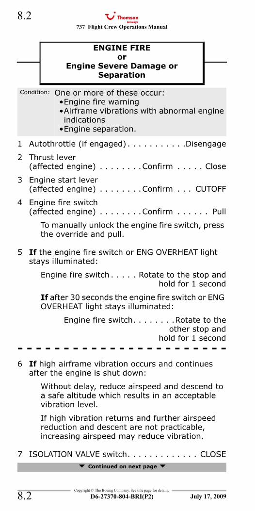
737 Flight Crew Operations Manual
Copyright © The Boeing Company. See title page for details.
D6-27370-804-BRI(P2)
8.2
8.2
FIRE WARN and Engine 1 - FireFIRE WARN and Engine 2 - FireEngine 1 - Fire and FIRE WARNEngine 2 - Fire and FIRE WARN
1 Autothrottle (if engaged) . . . . . . . . . . .Disengage
2 Thrust lever(affected engine) . . . . . . . .Confirm . . . . . Close
3 Engine start lever(affected engine) . . . . . . . .Confirm . . . CUTOFF
4 Engine fire switch(affected engine) . . . . . . . .Confirm . . . . . . Pull
To manually unlock the engine fire switch, press the override and pull.
5 If the engine fire switch or ENG OVERHEAT light stays illuminated:
Engine fire switch . . . . . Rotate to the stop andhold for 1 second
If after 30 seconds the engine fire switch or ENG OVERHEAT light stays illuminated:
Engine fire switch. . . . . . . .Rotate to theother stop and
hold for 1 second- - - - - - - - - - - - - - - - - - - - - - -6 If high airframe vibration occurs and continues
after the engine is shut down:
Without delay, reduce airspeed and descend to a safe altitude which results in an acceptable vibration level.
If high vibration returns and further airspeed reduction and descent are not practicable, increasing airspeed may reduce vibration.
7 ISOLATION VALVE switch. . . . . . . . . . . . . CLOSE Continued on next page
ENGINE FIREor
Engine Severe Damage orSeparation
ENGINE FIRE or Engine Severe Damage or Separation
Condition: One or more of these occur:•Engine fire warning•Airframe vibrations with abnormal engine indications
•Engine separation.
July 17, 2009
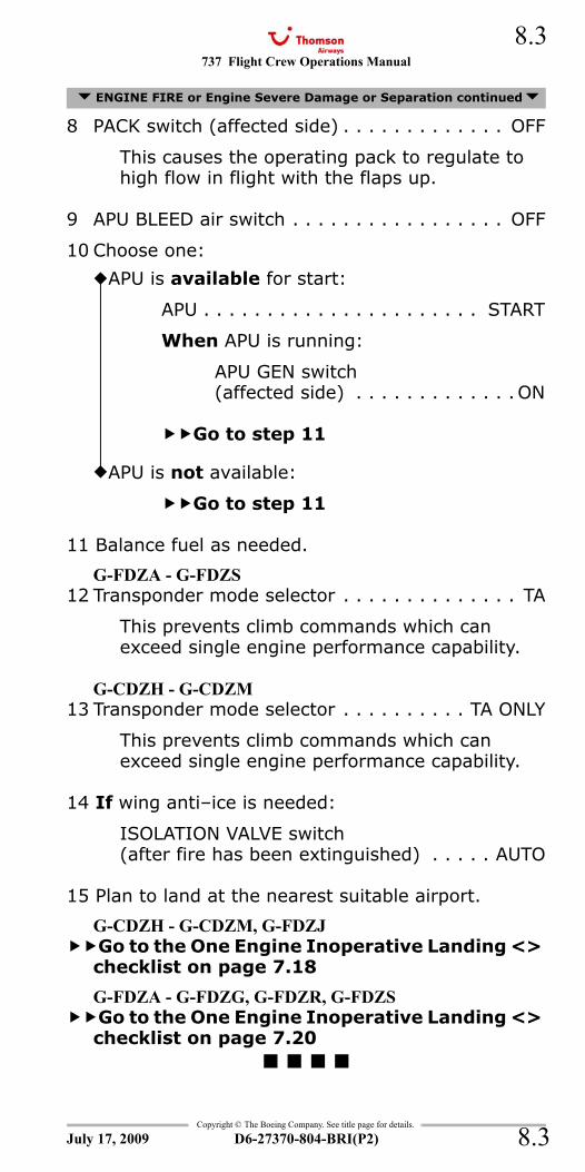
737 Flight Crew Operations Manual 8.3
Copyright © The Boeing Company. See title page for details.
D6-27370-804-BRI(P2) 8.3
8 PACK switch (affected side) . . . . . . . . . . . . . OFF
This causes the operating pack to regulate to high flow in flight with the flaps up.
9 APU BLEED air switch . . . . . . . . . . . . . . . . . OFF
10 Choose one:
11 Balance fuel as needed.
G-FDZA - G-FDZS12 Transponder mode selector . . . . . . . . . . . . . . TA
This prevents climb commands which can exceed single engine performance capability.
G-CDZH - G-CDZM13 Transponder mode selector . . . . . . . . . . TA ONLY
This prevents climb commands which can exceed single engine performance capability.
14 If wing anti–ice is needed:
ISOLATION VALVE switch(after fire has been extinguished) . . . . . AUTO
15 Plan to land at the nearest suitable airport.
G-CDZH - G-CDZM, G-FDZJGo to the One Engine Inoperative Landing <> checklist on page 7.18
G-FDZA - G-FDZG, G-FDZR, G-FDZSGo to the One Engine Inoperative Landing <> checklist on page 7.20
ENGINE FIRE or Engine Severe Damage or Separation continued
APU is available for start:
APU . . . . . . . . . . . . . . . . . . . . . . START
When APU is running:
APU GEN switch(affected side) . . . . . . . . . . . . .ON
Go to step 11
APU is not available:
Go to step 11
July 17, 2009
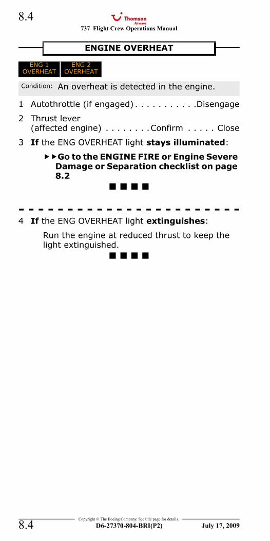
737 Flight Crew Operations Manual
Copyright © The Boeing Company. See title page for details.
D6-27370-804-BRI(P2)
8.4
8.4
ENG 1 OVERHEATENG 2 OVERHEAT
1 Autothrottle (if engaged) . . . . . . . . . . .Disengage
2 Thrust lever(affected engine) . . . . . . . .Confirm . . . . . Close
3 If the ENG OVERHEAT light stays illuminated:
Go to the ENGINE FIRE or Engine Severe Damage or Separation checklist on page 8.2
- - - - - - - - - - - - - - - - - - - - - - -4 If the ENG OVERHEAT light extinguishes:
Run the engine at reduced thrust to keep the light extinguished.
ENGINE OVERHEAT
ENG 1OVERHEAT
ENG 2OVERHEAT
Condition: An overheat is detected in the engine.
July 17, 2009
737 Flight Crew Operations Manual 8.5
Copyright © The Boeing Company. See title page for details.
D6-27370-804-BRI(P2) 8.5
IntentionallyBlank
July 17, 2009
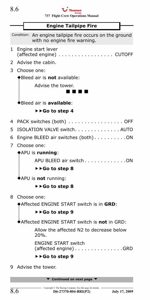
737 Flight Crew Operations Manual
Copyright © The Boeing Company. See title page for details.
D6-27370-804-BRI(P2)
8.6
8.6
1 Engine start lever (affected engine) . . . . . . . . . . . . . . . . . CUTOFF
2 Advise the cabin.
3 Choose one:
4 PACK switches (both) . . . . . . . . . . . . . . . . . OFF
5 ISOLATION VALVE switch. . . . . . . . . . . . . . AUTO
6 Engine BLEED air switches (both) . . . . . . . . . .ON
7 Choose one:
8 Choose one:
9 Advise the tower.
Continued on next page
Engine Tailpipe Fire
Condition: An engine tailpipe fire occurs on the ground with no engine fire warning.
Bleed air is not available:
Advise the tower.
Bleed air is available:
Go to step 4
APU is running:
APU BLEED air switch . . . . . . . . . . . . .ON
Go to step 8
APU is not running:
Go to step 8
Affected ENGINE START switch is in GRD:
Go to step 9
Affected ENGINE START switch is not in GRD:
Allow the affected N2 to decrease below 20%.
ENGINE START switch(affected engine) . . . . . . . . . . . . . . .GRD
Go to step 9
July 17, 2009
737 Flight Crew Operations Manual 8.7
Copyright © The Boeing Company. See title page for details.
D6-27370-804-BRI(P2) 8.7
10 Continue to motor the engine until the tailpipe fire is extinguished.
11 ENGINE START switch (affected engine) . . . . OFF
Engine Tailpipe Fire continued
July 17, 2009
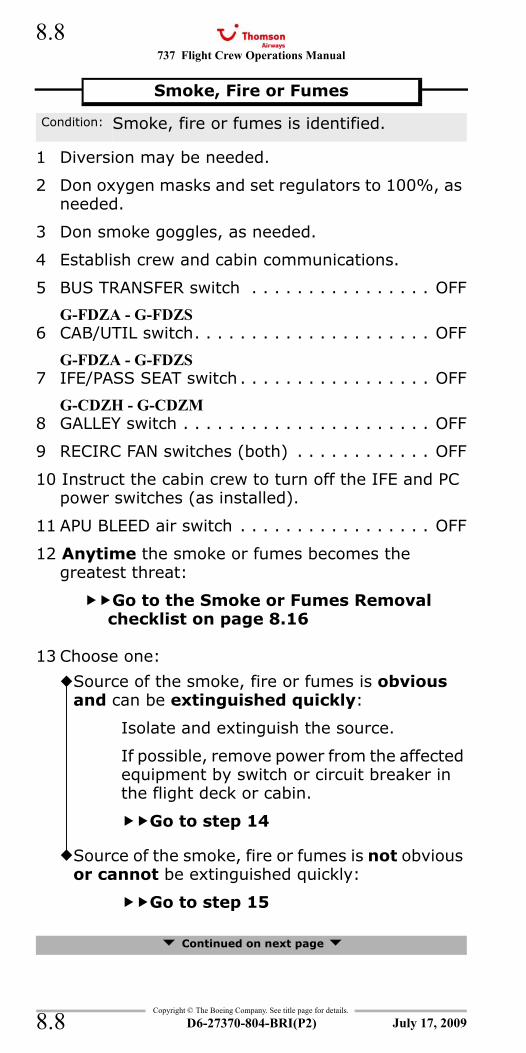
737 Flight Crew Operations Manual
Copyright © The Boeing Company. See title page for details.
D6-27370-804-BRI(P2)
8.8
8.8
1 Diversion may be needed.
2 Don oxygen masks and set regulators to 100%, as needed.
3 Don smoke goggles, as needed.
4 Establish crew and cabin communications.
5 BUS TRANSFER switch . . . . . . . . . . . . . . . . OFF
G-FDZA - G-FDZS6 CAB/UTIL switch. . . . . . . . . . . . . . . . . . . . . OFF
G-FDZA - G-FDZS7 IFE/PASS SEAT switch . . . . . . . . . . . . . . . . . OFF
G-CDZH - G-CDZM8 GALLEY switch . . . . . . . . . . . . . . . . . . . . . . OFF
9 RECIRC FAN switches (both) . . . . . . . . . . . . OFF
10 Instruct the cabin crew to turn off the IFE and PC power switches (as installed).
11 APU BLEED air switch . . . . . . . . . . . . . . . . . OFF
12 Anytime the smoke or fumes becomes the greatest threat:
Go to the Smoke or Fumes Removal checklist on page 8.16
13 Choose one:
Continued on next page
Smoke, Fire or Fumes
Condition: Smoke, fire or fumes is identified.
Source of the smoke, fire or fumes is obvious and can be extinguished quickly:
Isolate and extinguish the source.
If possible, remove power from the affected equipment by switch or circuit breaker in the flight deck or cabin.
Go to step 14
Source of the smoke, fire or fumes is not obvious or cannot be extinguished quickly:
Go to step 15
July 17, 2009
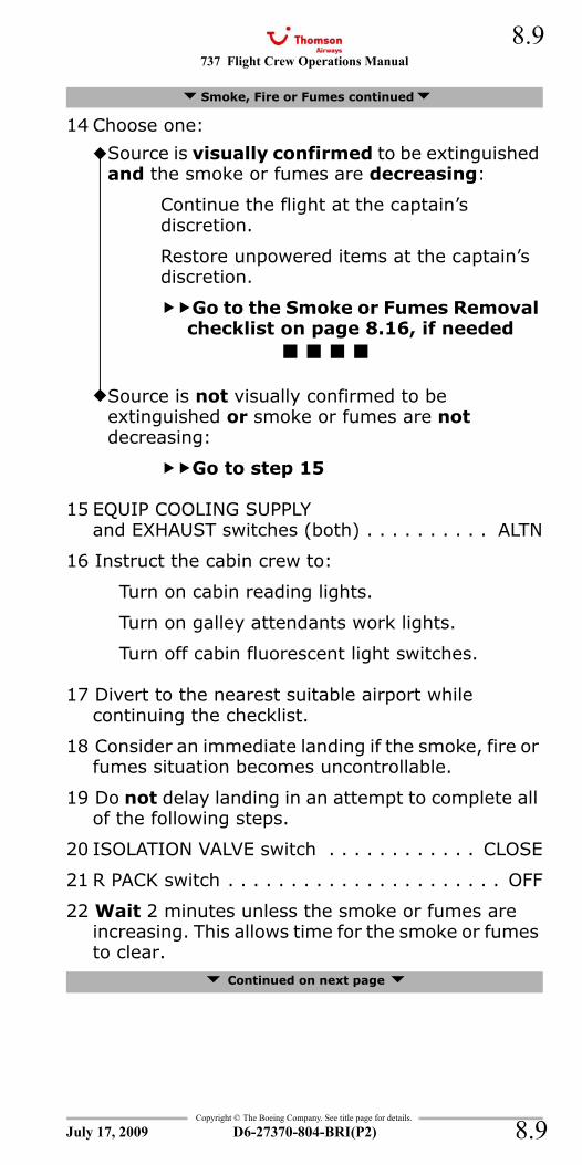
737 Flight Crew Operations Manual 8.9
Copyright © The Boeing Company. See title page for details.
D6-27370-804-BRI(P2) 8.9
14 Choose one:
15 EQUIP COOLING SUPPLYand EXHAUST switches (both) . . . . . . . . . . ALTN
16 Instruct the cabin crew to:
Turn on cabin reading lights.
Turn on galley attendants work lights.
Turn off cabin fluorescent light switches.
17 Divert to the nearest suitable airport while continuing the checklist.
18 Consider an immediate landing if the smoke, fire or fumes situation becomes uncontrollable.
19 Do not delay landing in an attempt to complete all of the following steps.
20 ISOLATION VALVE switch . . . . . . . . . . . . CLOSE
21 R PACK switch . . . . . . . . . . . . . . . . . . . . . . OFF
22 Wait 2 minutes unless the smoke or fumes are increasing. This allows time for the smoke or fumes to clear.
Continued on next page
Smoke, Fire or Fumes continued
Source is visually confirmed to be extinguished and the smoke or fumes are decreasing:
Continue the flight at the captain’s discretion.
Restore unpowered items at the captain’s discretion.
Go to the Smoke or Fumes Removal checklist on page 8.16, if needed
Source is not visually confirmed to be extinguished or smoke or fumes are not decreasing:
Go to step 15
July 17, 2009
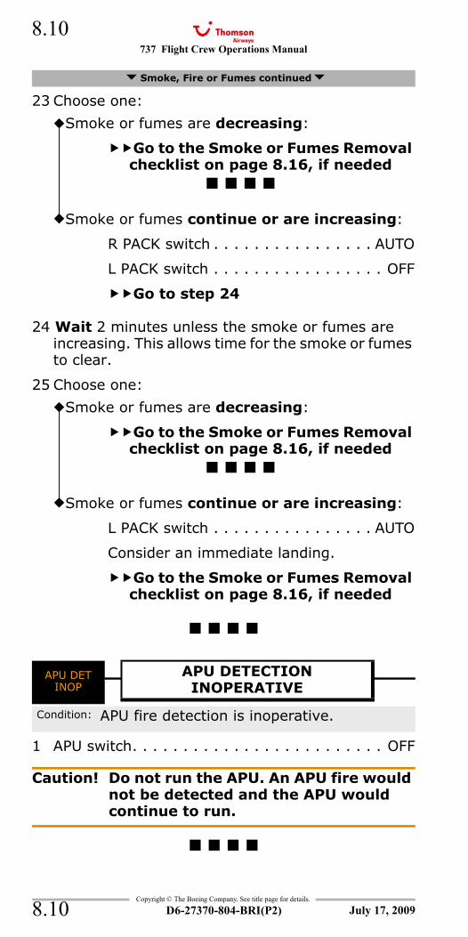
737 Flight Crew Operations Manual
Copyright © The Boeing Company. See title page for details.
D6-27370-804-BRI(P2)
8.10
8.10
23 Choose one:
24 Wait 2 minutes unless the smoke or fumes are increasing. This allows time for the smoke or fumes to clear.
25 Choose one:
APU DET INOP
1 APU switch. . . . . . . . . . . . . . . . . . . . . . . . . OFF
Caution! Do not run the APU. An APU fire would not be detected and the APU would continue to run.
Smoke, Fire or Fumes continued
Smoke or fumes are decreasing:
Go to the Smoke or Fumes Removal checklist on page 8.16, if needed
Smoke or fumes continue or are increasing:
R PACK switch . . . . . . . . . . . . . . . . AUTO
L PACK switch . . . . . . . . . . . . . . . . . OFF
Go to step 24
Smoke or fumes are decreasing:
Go to the Smoke or Fumes Removal checklist on page 8.16, if needed
Smoke or fumes continue or are increasing:
L PACK switch . . . . . . . . . . . . . . . . AUTO
Consider an immediate landing.
Go to the Smoke or Fumes Removal checklist on page 8.16, if needed
APU DETINOP
APU DETECTIONINOPERATIVE
Condition: APU fire detection is inoperative.
July 17, 2009

737 Flight Crew Operations Manual 8.11
Copyright © The Boeing Company. See title page for details.
D6-27370-804-BRI(P2) 8.11
IntentionallyBlank
July 17, 2009
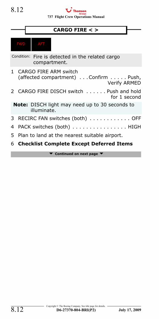
737 Flight Crew Operations Manual
Copyright © The Boeing Company. See title page for details.
D6-27370-804-BRI(P2)
8.12
8.12
FIRE WARN and FWD - Cargo FireFIRE WARN and AFT - Cargo FireFWD - Cargo Fire and FIRE WARNAFT - Cargo Fire and FIRE WARN
1 CARGO FIRE ARM switch(affected compartment) . . .Confirm . . . . . Push,
Verify ARMED
2 CARGO FIRE DISCH switch . . . . . . Push and holdfor 1 second
3 RECIRC FAN switches (both) . . . . . . . . . . . . OFF
4 PACK switches (both) . . . . . . . . . . . . . . . . HIGH
5 Plan to land at the nearest suitable airport.
6 Checklist Complete Except Deferred Items
Continued on next page
CARGO FIRE < >
FWD AFT
Condition: Fire is detected in the related cargo compartment.
Note: DISCH light may need up to 30 seconds to illuminate.
July 17, 2009
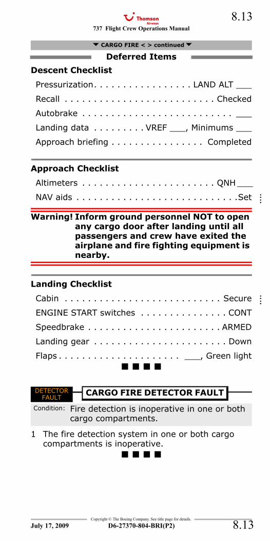
737 Flight Crew Operations Manual 8.13
Copyright © The Boeing Company. See title page for details.
D6-27370-804-BRI(P2) 8.13
Descent Checklist
Pressurization. . . . . . . . . . . . . . . . . LAND ALT ___
Recall . . . . . . . . . . . . . . . . . . . . . . . . . . Checked
Autobrake . . . . . . . . . . . . . . . . . . . . . . . . . . ___
Landing data . . . . . . . . . VREF ___, Minimums ___
Approach briefing . . . . . . . . . . . . . . . . Completed
Approach Checklist
Altimeters . . . . . . . . . . . . . . . . . . . . . . . QNH ___
NAV aids . . . . . . . . . . . . . . . . . . . . . . . . . . . .Set
Warning! Inform ground personnel NOT to open any cargo door after landing until all passengers and crew have exited the airplane and fire fighting equipment is nearby.
Landing Checklist
Cabin . . . . . . . . . . . . . . . . . . . . . . . . . . . Secure
ENGINE START switches . . . . . . . . . . . . . . . CONT
Speedbrake . . . . . . . . . . . . . . . . . . . . . . . ARMED
Landing gear . . . . . . . . . . . . . . . . . . . . . . . Down
Flaps . . . . . . . . . . . . . . . . . . . . . ___, Green light
DETECTOR FAULT
1 The fire detection system in one or both cargo compartments is inoperative.
CARGO FIRE < > continued
Deferred Items
DETECTORFAULT
CARGO FIRE DETECTOR FAULT
Condition: Fire detection is inoperative in one or both cargo compartments.
July 17, 2009
::::
::::
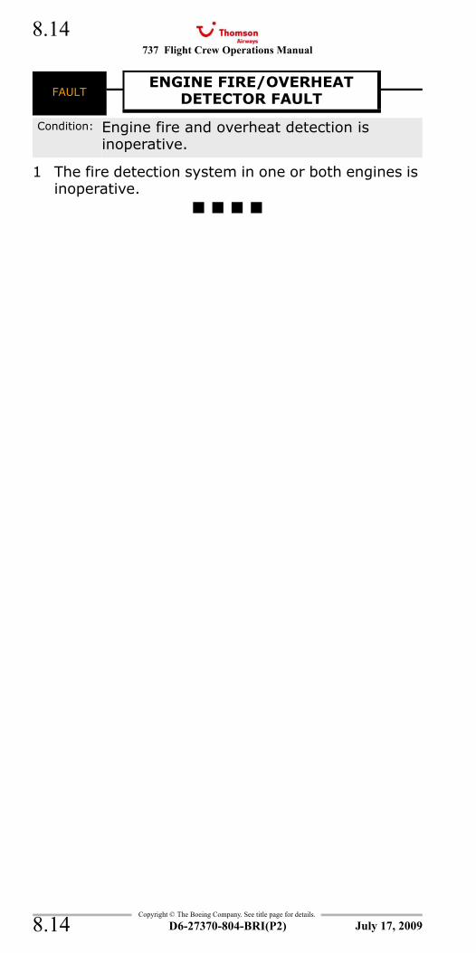
737 Flight Crew Operations Manual
Copyright © The Boeing Company. See title page for details.
D6-27370-804-BRI(P2)
8.14
8.14
FAULT - Engine Fire/Overheat Detector
1 The fire detection system in one or both engines is inoperative.
FAULTENGINE FIRE/OVERHEAT
DETECTOR FAULT
Condition: Engine fire and overheat detection is inoperative.
July 17, 2009

737 Flight Crew Operations Manual 8.15
Copyright © The Boeing Company. See title page for details.
D6-27370-804-BRI(P2) 8.15
IntentionallyBlank
July 17, 2009
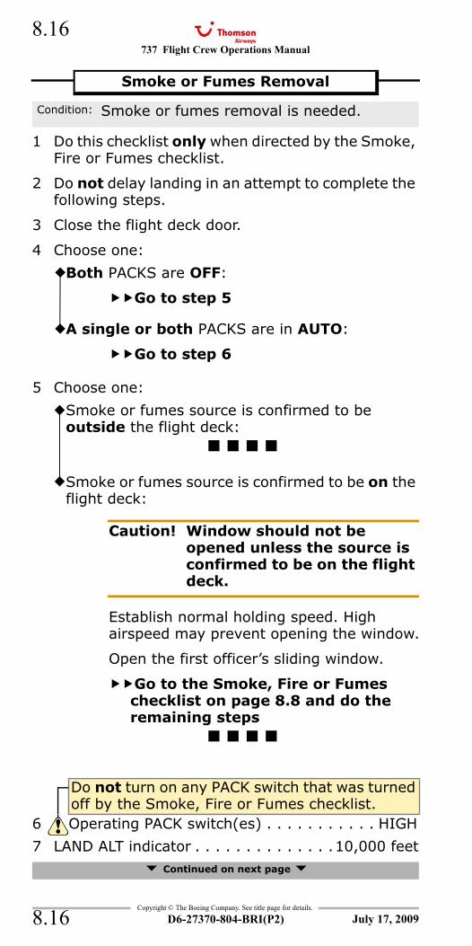
737 Flight Crew Operations Manual
Copyright © The Boeing Company. See title page for details.
D6-27370-804-BRI(P2)
8.16
8.16
1 Do this checklist only when directed by the Smoke, Fire or Fumes checklist.
2 Do not delay landing in an attempt to complete the following steps.
3 Close the flight deck door.
4 Choose one:
5 Choose one:
7 LAND ALT indicator . . . . . . . . . . . . . .10,000 feet Continued on next page
Smoke or Fumes Removal
Condition: Smoke or fumes removal is needed.
Both PACKS are OFF:
Go to step 5
A single or both PACKS are in AUTO:
Go to step 6
Smoke or fumes source is confirmed to be outside the flight deck:
Smoke or fumes source is confirmed to be on the flight deck:
Caution! Window should not be opened unless the source is confirmed to be on the flight deck.
Establish normal holding speed. High airspeed may prevent opening the window.
Open the first officer’s sliding window.
Go to the Smoke, Fire or Fumes checklist on page 8.8 and do the remaining steps
Do not turn on any PACK switch that was turned off by the Smoke, Fire or Fumes checklist.
6 Operating PACK switch(es) . . . . . . . . . . . HIGH
July 17, 2009
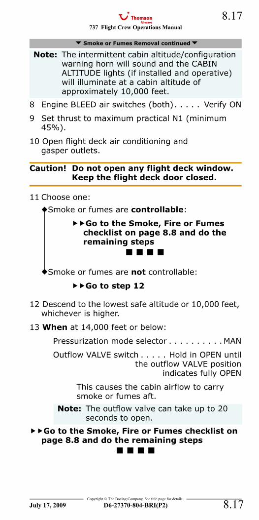
737 Flight Crew Operations Manual 8.17
Copyright © The Boeing Company. See title page for details.
D6-27370-804-BRI(P2) 8.17
8 Engine BLEED air switches (both). . . . . Verify ON
9 Set thrust to maximum practical N1 (minimum 45%).
10 Open flight deck air conditioning and gasper outlets.
Caution! Do not open any flight deck window. Keep the flight deck door closed.
11 Choose one:
12 Descend to the lowest safe altitude or 10,000 feet, whichever is higher.
13 When at 14,000 feet or below:
Pressurization mode selector . . . . . . . . . .MAN
Outflow VALVE switch . . . . . Hold in OPEN untilthe outflow VALVE position
indicates fully OPEN
This causes the cabin airflow to carry smoke or fumes aft.
Go to the Smoke, Fire or Fumes checklist on page 8.8 and do the remaining steps
Smoke or Fumes Removal continued
Note: The intermittent cabin altitude/configuration warning horn will sound and the CABIN ALTITUDE lights (if installed and operative) will illuminate at a cabin altitude of approximately 10,000 feet.
Smoke or fumes are controllable:
Go to the Smoke, Fire or Fumes checklist on page 8.8 and do the remaining steps
Smoke or fumes are not controllable:
Go to step 12
Note: The outflow valve can take up to 20 seconds to open.
July 17, 2009
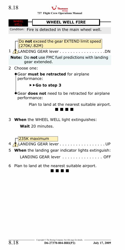
737 Flight Crew Operations Manual
Copyright © The Boeing Company. See title page for details.
D6-27370-804-BRI(P2)
8.18
8.18
WHEEL WELL - Fire and FIRE WARNFIRE WARN and WHEEL WELL - Fire
2 Choose one:
3 When the WHEEL WELL light extinguishes:
Wait 20 minutes.
5 When the landing gear indicator lights extinguish:
LANDING GEAR lever . . . . . . . . . . . . . . . OFF
6 Plan to land at the nearest suitable airport.
WHEEL WELL
WHEEL WELL FIRE
Condition: Fire is detected in the main wheel well.
Do not exceed the gear EXTEND limit speed (270K/.82M)
1 LANDING GEAR lever . . . . . . . . . . . . . . . . .DN
Note: Do not use FMC fuel predictions with landing gear extended.
Gear must be retracted for airplane performance:
Go to step 3
Gear does not need to be retracted for airplane performance:
Plan to land at the nearest suitable airport.
235K maximum4 LANDING GEAR lever . . . . . . . . . . . . . . . . . UP
July 17, 2009
737 Flight Crew Operations Manual
Non-Normal Checklists Chapter NNCFlight Controls Section 9
Table of Contents
Copyright © The Boeing Company. See title page for details.
D6-27370-804-BRI(P2) 9.TOC.1
Runaway Stabilizer <> .................................9.1
All Flaps Up Landing <>....................................9.3AUTO SLAT FAIL ..............................................9.5FEEL DIFFERENTIAL PRESSURE..........................9.5FLAP LOAD RELIEF ...........................................9.5FLIGHT CONTROL LOW PRESSURE......................9.5Jammed or Restricted Flight Controls <>.............9.6LEADING EDGE FLAPS TRANSIT <>....................9.9MACH TRIM FAIL............................................9.11Runaway Stabilizer <> .................................9.1SPEED BRAKE DO NOT ARM <> .......................9.12SPEED TRIM FAIL ...........................................9.12SPEEDBRAKES EXTENDED...............................9.13STABILIZER OUT OF TRIM...............................9.14Stabilizer Trim Inoperative <>.........................9.15STANDBY RUDDER ON ....................................9.17Trailing Edge Flap Asymmetry <> ....................9.18Trailing Edge Flap Disagree <> ........................9.21Trailing Edge Flaps Up Landing <> ...................9.26YAW DAMPER ................................................9.29
July 17, 2009
NNC.9-Flight ControlsTable Of Contents

737 Flight Crew Operations Manual
Non-Normal Checklists -Flight Controls
Table of Contents
Copyright © The Boeing Company. See title page for details.
D6-27370-804-BRI(P2)9.TOC.2
IntentionallyBlank
July 17, 2009
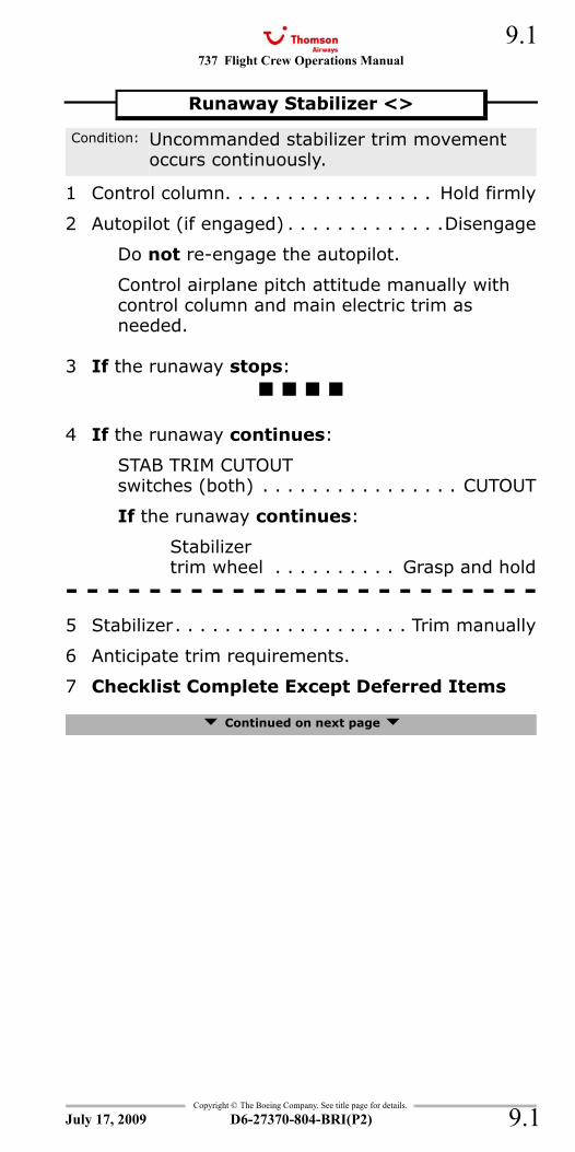
737 Flight Crew Operations Manual 9.1
Copyright © The Boeing Company. See title page for details.
D6-27370-804-BRI(P2) 9.1
NNC.9 Non-Normal Checklists-Flight Controls
1 Control column. . . . . . . . . . . . . . . . . Hold firmly
2 Autopilot (if engaged) . . . . . . . . . . . . .Disengage
Do not re-engage the autopilot.
Control airplane pitch attitude manually with control column and main electric trim as needed.
3 If the runaway stops:
4 If the runaway continues:
STAB TRIM CUTOUT switches (both) . . . . . . . . . . . . . . . . CUTOUT
If the runaway continues:
Stabilizer trim wheel . . . . . . . . . . Grasp and hold
- - - - - - - - - - - - - - - - - - - - - - -5 Stabilizer. . . . . . . . . . . . . . . . . . . Trim manually
6 Anticipate trim requirements.
7 Checklist Complete Except Deferred Items
Continued on next page
Runaway Stabilizer <>
Condition: Uncommanded stabilizer trim movement occurs continuously.
July 17, 2009
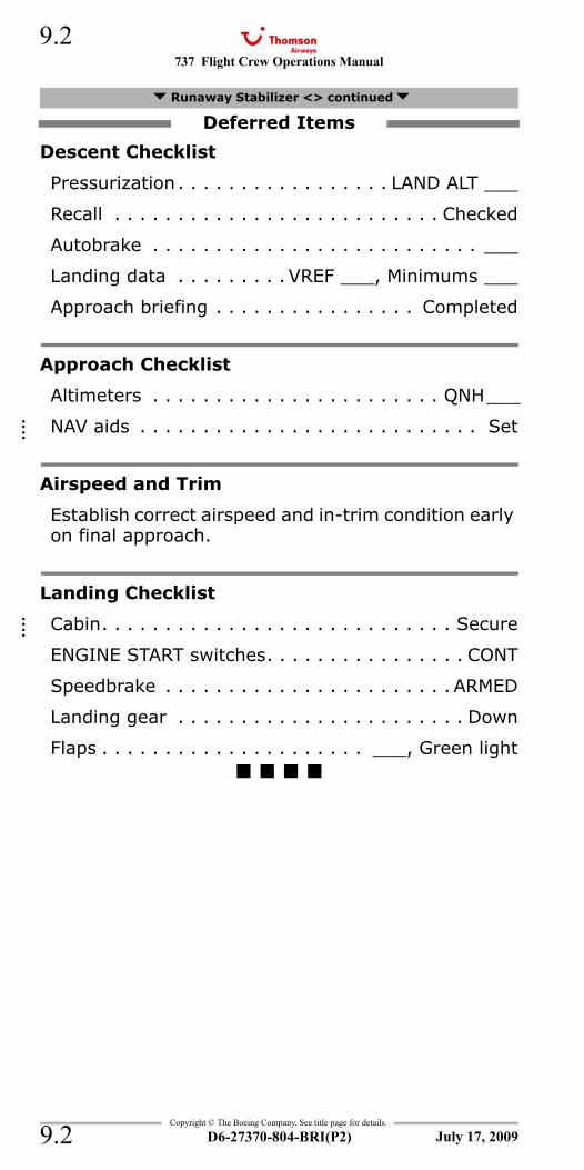
737 Flight Crew Operations Manual
Copyright © The Boeing Company. See title page for details.
D6-27370-804-BRI(P2)
9.2
9.2
Descent Checklist
Pressurization. . . . . . . . . . . . . . . . . LAND ALT ___
Recall . . . . . . . . . . . . . . . . . . . . . . . . . . Checked
Autobrake . . . . . . . . . . . . . . . . . . . . . . . . . . ___
Landing data . . . . . . . . . VREF ___, Minimums ___
Approach briefing . . . . . . . . . . . . . . . . Completed
Approach Checklist
Altimeters . . . . . . . . . . . . . . . . . . . . . . . QNH___
NAV aids . . . . . . . . . . . . . . . . . . . . . . . . . . . Set
Airspeed and Trim
Establish correct airspeed and in-trim condition early on final approach.
Landing Checklist
Cabin. . . . . . . . . . . . . . . . . . . . . . . . . . . . Secure
ENGINE START switches. . . . . . . . . . . . . . . . CONT
Speedbrake . . . . . . . . . . . . . . . . . . . . . . . ARMED
Landing gear . . . . . . . . . . . . . . . . . . . . . . . Down
Flaps . . . . . . . . . . . . . . . . . . . . . ___, Green light
Runaway Stabilizer <> continued
Deferred Items
July 17, 2009
::::
::::
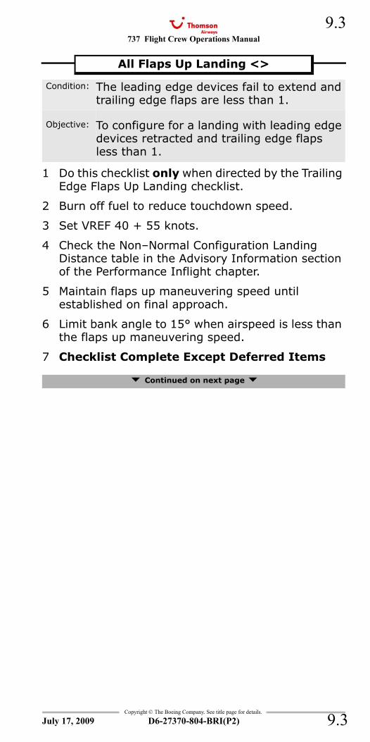
737 Flight Crew Operations Manual 9.3
Copyright © The Boeing Company. See title page for details.
D6-27370-804-BRI(P2) 9.3
1 Do this checklist only when directed by the Trailing Edge Flaps Up Landing checklist.
2 Burn off fuel to reduce touchdown speed.
3 Set VREF 40 + 55 knots.
4 Check the Non–Normal Configuration Landing Distance table in the Advisory Information section of the Performance Inflight chapter.
5 Maintain flaps up maneuvering speed until established on final approach.
6 Limit bank angle to 15° when airspeed is less than the flaps up maneuvering speed.
7 Checklist Complete Except Deferred Items
Continued on next page
All Flaps Up Landing <>
Condition: The leading edge devices fail to extend and trailing edge flaps are less than 1.
Objective: To configure for a landing with leading edge devices retracted and trailing edge flaps less than 1.
July 17, 2009
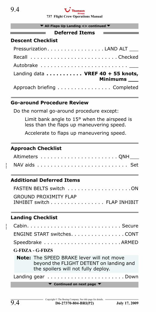
737 Flight Crew Operations Manual
Copyright © The Boeing Company. See title page for details.
D6-27370-804-BRI(P2)
9.4
9.4
Descent Checklist
Pressurization. . . . . . . . . . . . . . . . . LAND ALT ___
Recall . . . . . . . . . . . . . . . . . . . . . . . . . . Checked
Autobrake . . . . . . . . . . . . . . . . . . . . . . . . . . ___
Landing data . . . . . . . . . . . VREF 40 + 55 knots,Minimums ___
Approach briefing . . . . . . . . . . . . . . . . Completed
Go-around Procedure Review
Do the normal go-around procedure except:
Limit bank angle to 15° when the airspeed is less than the flaps up maneuvering speed.
Accelerate to flaps up maneuvering speed.
Approach Checklist
Altimeters . . . . . . . . . . . . . . . . . . . . . . . QNH___
NAV aids . . . . . . . . . . . . . . . . . . . . . . . . . . . Set
Additional Deferred Items
FASTEN BELTS switch . . . . . . . . . . . . . . . . . . .ON
GROUND PROXIMITY FLAPINHIBIT switch . . . . . . . . . . . . . . . . FLAP INHIBIT
Landing Checklist
Cabin. . . . . . . . . . . . . . . . . . . . . . . . . . . . Secure
ENGINE START switches. . . . . . . . . . . . . . . . CONT
Speedbrake . . . . . . . . . . . . . . . . . . . . . . . ARMED
G-FDZA - G-FDZS
Landing gear . . . . . . . . . . . . . . . . . . . . . . . Down Continued on next page
All Flaps Up Landing <> continued
Deferred Items
Note: The SPEED BRAKE lever will not move beyond the FLIGHT DETENT on landing and the spoilers will not fully deploy.
July 17, 2009
::::
::::
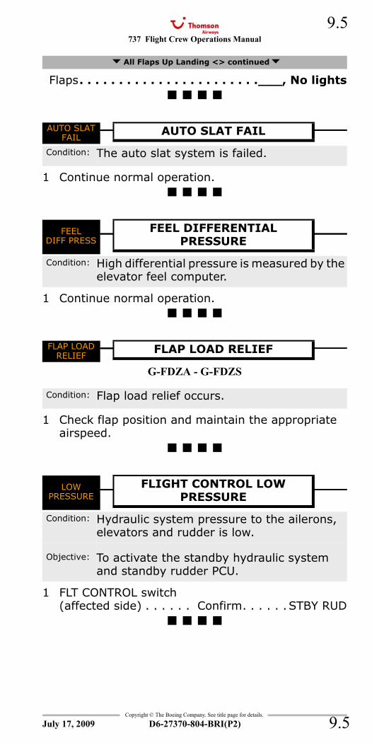
737 Flight Crew Operations Manual 9.5
Copyright © The Boeing Company. See title page for details.
D6-27370-804-BRI(P2) 9.5
Flaps. . . . . . . . . . . . . . . . . . . . . . .___, No lights
AUTO SLAT FAIL
1 Continue normal operation.
FEEL DIFF PRESS
1 Continue normal operation.
FLAP LOAD RELIEF
G-FDZA - G-FDZS
1 Check flap position and maintain the appropriate airspeed.
LOW PRESSURE - Flight Control
1 FLT CONTROL switch(affected side) . . . . . . Confirm. . . . . . STBY RUD
All Flaps Up Landing <> continued
AUTO SLAT FAIL
AUTO SLAT FAIL
Condition: The auto slat system is failed.
FEELDIFF PRESS
FEEL DIFFERENTIALPRESSURE
Condition: High differential pressure is measured by the elevator feel computer.
FLAP LOADRELIEF
FLAP LOAD RELIEF
Condition: Flap load relief occurs.
LOWPRESSURE
FLIGHT CONTROL LOWPRESSURE
Condition: Hydraulic system pressure to the ailerons, elevators and rudder is low.
Objective: To activate the standby hydraulic system and standby rudder PCU.
July 17, 2009
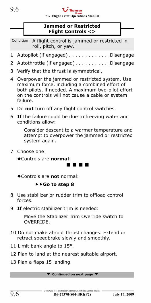
737 Flight Crew Operations Manual
Copyright © The Boeing Company. See title page for details.
D6-27370-804-BRI(P2)
9.6
9.6
1 Autopilot (if engaged) . . . . . . . . . . . . .Disengage
2 Autothrottle (if engaged) . . . . . . . . . . .Disengage
3 Verify that the thrust is symmetrical.
4 Overpower the jammed or restricted system. Use maximum force, including a combined effort of both pilots, if needed. A maximum two-pilot effort on the controls will not cause a cable or system failure.
5 Do not turn off any flight control switches.
6 If the failure could be due to freezing water and conditions allow:
Consider descent to a warmer temperature and attempt to overpower the jammed or restricted system again.
7 Choose one:
8 Use stabilizer or rudder trim to offload control forces.
9 If electric stabilizer trim is needed:
Move the Stabilizer Trim Override switch to OVERRIDE.
10 Do not make abrupt thrust changes. Extend or retract speedbrake slowly and smoothly.
11 Limit bank angle to 15°.
12 Plan to land at the nearest suitable airport.
13 Plan a flaps 15 landing.
Continued on next page
Jammed or RestrictedFlight Controls <>
Condition: A flight control is jammed or restricted in roll, pitch, or yaw.
Controls are normal:
Controls are not normal:
Go to step 8
July 17, 2009
737 Flight Crew Operations Manual 9.7
Copyright © The Boeing Company. See title page for details.
D6-27370-804-BRI(P2) 9.7
14 Set VREF 15 or VREF ICE.
If any of the following conditions apply, set VREF ICE = VREF 15 + 10 knots:
Engine anti–ice will be used during landing
Wing anti–ice has been used any time during the flight
Icing conditions were encountered during the flight and the landing temperature is below 10° C.
15 Check the Non–Normal Configuration Landing Distance table in the Advisory Information section of the Performance Inflight chapter.
16 Checklist Complete Except Deferred Items
Continued on next page
Jammed or Restricted Flight Controls <> continued
Note: When VREF ICE is needed, the wind additive should not exceed 10 knots.
July 17, 2009
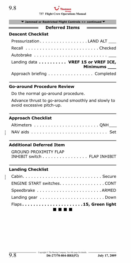
737 Flight Crew Operations Manual
Copyright © The Boeing Company. See title page for details.
D6-27370-804-BRI(P2)
9.8
9.8
Descent Checklist
Pressurization. . . . . . . . . . . . . . . . . LAND ALT ___
Recall . . . . . . . . . . . . . . . . . . . . . . . . . . Checked
Autobrake . . . . . . . . . . . . . . . . . . . . . . . . . . ___
Landing data . . . . . . . . . . VREF 15 or VREF ICE,Minimums ___
Approach briefing . . . . . . . . . . . . . . . . Completed
Go-around Procedure Review
Do the normal go-around procedure.
Advance thrust to go-around smoothly and slowly to avoid excessive pitch-up.
Approach Checklist
Altimeters . . . . . . . . . . . . . . . . . . . . . . . QNH___
NAV aids . . . . . . . . . . . . . . . . . . . . . . . . . . . Set
Additional Deferred Item
GROUND PROXIMITY FLAPINHIBIT switch . . . . . . . . . . . . . . . . FLAP INHIBIT
Landing Checklist
Cabin. . . . . . . . . . . . . . . . . . . . . . . . . . . . Secure
ENGINE START switches. . . . . . . . . . . . . . . . CONT
Speedbrake . . . . . . . . . . . . . . . . . . . . . . . ARMED
Landing gear . . . . . . . . . . . . . . . . . . . . . . . Down
Flaps . . . . . . . . . . . . . . . . . . . . . .15, Green light
Jammed or Restricted Flight Controls <> continued
Deferred Items
July 17, 2009
::::
::::
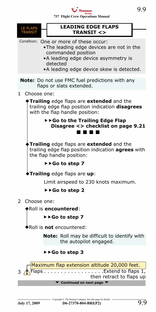
737 Flight Crew Operations Manual 9.9
Copyright © The Boeing Company. See title page for details.
D6-27370-804-BRI(P2) 9.9
LE FLAPS TRANSIT
1 Choose one:
2 Choose one:
Continued on next page
LE FLAPSTRANSIT
LEADING EDGE FLAPSTRANSIT <>
Condition: One or more of these occur:•The leading edge devices are not in the commanded position
•A leading edge device asymmetry is detected
•A leading edge device skew is detected.
Note: Do not use FMC fuel predictions with any flaps or slats extended.
Trailing edge flaps are extended and the trailing edge flap position indication disagrees with the flap handle position:
Go to the Trailing Edge Flap Disagree <> checklist on page 9.21
Trailing edge flaps are extended and the trailing edge flap position indication agrees with the flap handle position:
Go to step 7
Trailing edge flaps are up:
Limit airspeed to 230 knots maximum.
Go to step 2
Roll is encountered:
Go to step 7
Roll is not encountered:
Note: Roll may be difficult to identify with the autopilot engaged.
Go to step 3
Maximum flap extension altitude 20,000 feet.3 Flaps . . . . . . . . . . . . . . . . . .Extend to flaps 1,
then retract to flaps up
July 17, 2009
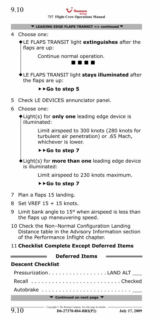
737 Flight Crew Operations Manual
Copyright © The Boeing Company. See title page for details.
D6-27370-804-BRI(P2)
9.10
9.10
4 Choose one:
5 Check LE DEVICES annunciator panel.
6 Choose one:
7 Plan a flaps 15 landing.
8 Set VREF 15 + 15 knots.
9 Limit bank angle to 15° when airspeed is less than the flaps up maneuvering speed.
10 Check the Non–Normal Configuration Landing Distance table in the Advisory Information section of the Performance Inflight chapter.
11 Checklist Complete Except Deferred Items
Descent Checklist
Pressurization. . . . . . . . . . . . . . . . . LAND ALT ___
Recall . . . . . . . . . . . . . . . . . . . . . . . . . . Checked
Autobrake . . . . . . . . . . . . . . . . . . . . . . . . . . ___ Continued on next page
LEADING EDGE FLAPS TRANSIT <> continued
LE FLAPS TRANSIT light extinguishes after the flaps are up:
Continue normal operation.
LE FLAPS TRANSIT light stays illuminated after the flaps are up:
Go to step 5
Light(s) for only one leading edge device is illuminated:
Limit airspeed to 300 knots (280 knots for turbulent air penetration) or .65 Mach, whichever is lower.
Go to step 7
Light(s) for more than one leading edge device is illuminated:
Limit airspeed to 230 knots maximum.
Go to step 7
Deferred Items
July 17, 2009
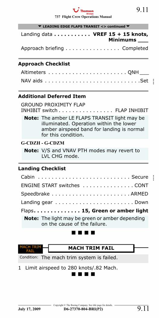
737 Flight Crew Operations Manual 9.11
Copyright © The Boeing Company. See title page for details.
D6-27370-804-BRI(P2) 9.11
Landing data . . . . . . . . . . . VREF 15 + 15 knots,Minimums ___
Approach briefing . . . . . . . . . . . . . . . . Completed
Approach Checklist
Altimeters . . . . . . . . . . . . . . . . . . . . . . . QNH ___
NAV aids . . . . . . . . . . . . . . . . . . . . . . . . . . . .Set
Additional Deferred Item
GROUND PROXIMITY FLAPINHIBIT switch . . . . . . . . . . . . . . . . FLAP INHIBIT
G-CDZH - G-CDZM
Landing Checklist
Cabin . . . . . . . . . . . . . . . . . . . . . . . . . . . Secure
ENGINE START switches . . . . . . . . . . . . . . . CONT
Speedbrake . . . . . . . . . . . . . . . . . . . . . . . ARMED
Landing gear . . . . . . . . . . . . . . . . . . . . . . . Down
Flaps. . . . . . . . . . . . . . 15, Green or amber light
MACH TRIM FAIL
1 Limit airspeed to 280 knots/.82 Mach.
LEADING EDGE FLAPS TRANSIT <> continued
Note: The amber LE FLAPS TRANSIT light may be illuminated. Operation within the lower amber airspeed band for landing is normal for this condition.
Note: V/S and VNAV PTH modes may revert to LVL CHG mode.
Note: The light may be green or amber depending on the cause of the failure.
MACH TRIMFAIL
MACH TRIM FAIL
Condition: The mach trim system is failed.
July 17, 2009
::::
::::
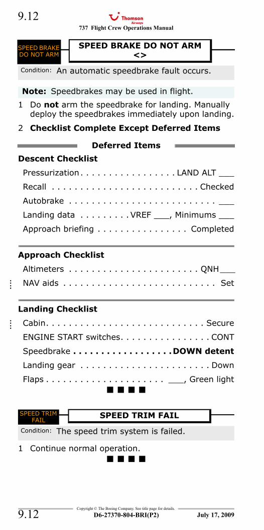
737 Flight Crew Operations Manual
Copyright © The Boeing Company. See title page for details.
D6-27370-804-BRI(P2)
9.12
9.12
SPEED BRAKE DO NOT ARM - Without Load Alleviation System
1 Do not arm the speedbrake for landing. Manually deploy the speedbrakes immediately upon landing.
2 Checklist Complete Except Deferred Items
Descent Checklist
Pressurization. . . . . . . . . . . . . . . . . LAND ALT ___
Recall . . . . . . . . . . . . . . . . . . . . . . . . . . Checked
Autobrake . . . . . . . . . . . . . . . . . . . . . . . . . . ___
Landing data . . . . . . . . . VREF ___, Minimums ___
Approach briefing . . . . . . . . . . . . . . . . Completed
Approach Checklist
Altimeters . . . . . . . . . . . . . . . . . . . . . . . QNH___
NAV aids . . . . . . . . . . . . . . . . . . . . . . . . . . . Set
Landing Checklist
Cabin. . . . . . . . . . . . . . . . . . . . . . . . . . . . Secure
ENGINE START switches. . . . . . . . . . . . . . . . CONT
Speedbrake . . . . . . . . . . . . . . . . . .DOWN detent
Landing gear . . . . . . . . . . . . . . . . . . . . . . . Down
Flaps . . . . . . . . . . . . . . . . . . . . . ___, Green light
SPEED TRIM FAIL
1 Continue normal operation.
SPEED BRAKE DO NOT ARM
SPEED BRAKE DO NOT ARM <>
Condition: An automatic speedbrake fault occurs.
Note: Speedbrakes may be used in flight.
Deferred Items
SPEED TRIM FAIL
SPEED TRIM FAIL
Condition: The speed trim system is failed.
July 17, 2009
::::
::::
737 Flight Crew Operations Manual 9.13
Copyright © The Boeing Company. See title page for details.
D6-27370-804-BRI(P2) 9.13
SPEEDBRAKES EXTENDED
1 SPEED BRAKE lever . . . . ARMED or DOWN detent
2 If the light is illuminated on the ground:
Do not takeoff.
SPEEDBRAKESEXTENDED
SPEEDBRAKES EXTENDED
Condition: In flight, the speedbrakes are extended beyond the ARMED position and one or more of these occur:•The radio altitude is below 800 feet•The flap lever setting is more than flaps 10.
On the ground, the SPEED BRAKE lever is down and the speedbrakes are extended.
July 17, 2009
737 Flight Crew Operations Manual
Copyright © The Boeing Company. See title page for details.
D6-27370-804-BRI(P2)
9.14
9.14
STAB OUT OF TRIM
1 Choose one:
2 Control column. . . . . . . . . . . . . . . . . Hold firmly
3 Autopilot . . . . . . . . . . . . . . . . . . . . . .Disengage
4 Stabilizer trim . . . . . . . . . . . . . . . . . .As needed
5 Choose one:
STABILIZER OUT OF TRIM
STABOUT OFTRIM
Condition: The autopilot does not set the stabilizer trim correctly.
Note: Momentary illumination of the STAB OUT OF TRIM light during large changes in trim requirements is normal.
Stabilizer is trimming:
Continue normal operation.
Stabilizer is not trimming:
Go to step 2
Stabilizer responds to electric trim inputs:
Stabilizer does not respond to electric trim inputs:
Go to the Stabilizer Trim Inoperative <> checklist on page 9.15
July 17, 2009
737 Flight Crew Operations Manual 9.15
Copyright © The Boeing Company. See title page for details.
D6-27370-804-BRI(P2) 9.15
1 STAB TRIM CUTOUT switches (both) . . . . CUTOUT
The autopilot is not available.
2 Apply steady pressure on the manual trim handles until the needed trim is attained.
3 If needed:
Use force to cause the disconnect clutch to disengage. Approximately 1/2 turn of the stabilizer trim wheel may be needed.
4 Choose one:
5 Maintain in-trim airspeed until the start of the approach.
6 Use an airspeed which results in an in-trim condition. This will reduce the force that is needed to move the stabilizer.
7 Continue to trim manually for the rest of the flight.
8 Establish the landing configuration early.
Continued on next page
Stabilizer Trim Inoperative <>
Condition: One or more of these occur:•The main electric stabilizer trim is inoperative
•The autopilot stabilizer trim is inoperative.
Note: A maximum two-pilot effort on the trim wheels will not cause a cable or system failure.
The handle(s) should be folded inside the stabilizer trim wheel when manual trim is no longer needed.
If the failure could be due to ice accumulation, descend to a warmer temperature and attempt again.
Stabilizer can be trimmed manually:
Go to step 5
Stabilizer can not be trimmed manually:
Go to step 9
July 17, 2009
737 Flight Crew Operations Manual
Copyright © The Boeing Company. See title page for details.
D6-27370-804-BRI(P2)
9.16
9.16
Go to step 11
9 Anticipate higher than normal elevator forces during approach and landing.
10 The thrust reduction at flare will cause a nose down pitch.
11 Plan a flaps 15 landing.
12 Set VREF 15 or VREF ICE.
If any of the following conditions apply, set VREF ICE = VREF 15 + 10 knots:
Engine anti–ice will be used during landing
Wing anti–ice has been used any time during the flight
Icing conditions were encountered during the flight and the landing temperature is below 10° C.
13 Check the Non–Normal Configuration Landing Distance table in the Advisory Information section of the Performance Inflight chapter.
14 Checklist Complete Except Deferred Items
Descent Checklist
Pressurization. . . . . . . . . . . . . . . . . LAND ALT ___
Recall . . . . . . . . . . . . . . . . . . . . . . . . . . Checked
Autobrake . . . . . . . . . . . . . . . . . . . . . . . . . . ___
Landing data . . . . . . . . . . VREF 15 or VREF ICE,Minimums ___
Approach briefing . . . . . . . . . . . . . . . . Completed
Go-around Procedure Review
Do the normal go-around procedure. Continued on next page
Stabilizer Trim Inoperative <> continued
Note: Elevator control is sufficient to safely land the airplane regardless of stabilizer position.
Note: When VREF ICE is needed, the wind additive should not exceed 10 knots.
Deferred Items
July 17, 2009
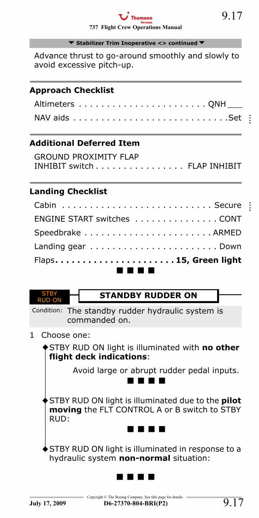
737 Flight Crew Operations Manual 9.17
Copyright © The Boeing Company. See title page for details.
D6-27370-804-BRI(P2) 9.17
Advance thrust to go-around smoothly and slowly to avoid excessive pitch-up.
Approach Checklist
Altimeters . . . . . . . . . . . . . . . . . . . . . . . QNH ___
NAV aids . . . . . . . . . . . . . . . . . . . . . . . . . . . .Set
Additional Deferred Item
GROUND PROXIMITY FLAPINHIBIT switch . . . . . . . . . . . . . . . . FLAP INHIBIT
Landing Checklist
Cabin . . . . . . . . . . . . . . . . . . . . . . . . . . . Secure
ENGINE START switches . . . . . . . . . . . . . . . CONT
Speedbrake . . . . . . . . . . . . . . . . . . . . . . . ARMED
Landing gear . . . . . . . . . . . . . . . . . . . . . . . Down
Flaps. . . . . . . . . . . . . . . . . . . . . . 15, Green light
STBY RUD ON
1 Choose one:
Stabilizer Trim Inoperative <> continued
STBYRUD ON
STANDBY RUDDER ON
Condition: The standby rudder hydraulic system is commanded on.
STBY RUD ON light is illuminated with no other flight deck indications:
Avoid large or abrupt rudder pedal inputs.
STBY RUD ON light is illuminated due to the pilot moving the FLT CONTROL A or B switch to STBY RUD:
STBY RUD ON light is illuminated in response to a hydraulic system non-normal situation:
July 17, 2009
::::
::::
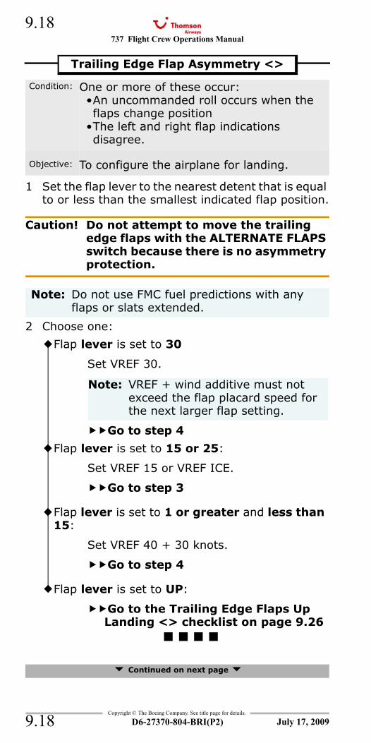
737 Flight Crew Operations Manual
Copyright © The Boeing Company. See title page for details.
D6-27370-804-BRI(P2)
9.18
9.18
1 Set the flap lever to the nearest detent that is equal to or less than the smallest indicated flap position.
Caution! Do not attempt to move the trailing edge flaps with the ALTERNATE FLAPS switch because there is no asymmetry protection.
2 Choose one:
Continued on next page
Trailing Edge Flap Asymmetry <>
Condition: One or more of these occur:•An uncommanded roll occurs when the flaps change position
•The left and right flap indications disagree.
Objective: To configure the airplane for landing.
Note: Do not use FMC fuel predictions with any flaps or slats extended.
Flap lever is set to 30
Set VREF 30.
Note: VREF + wind additive must not exceed the flap placard speed for the next larger flap setting.
Go to step 4
Flap lever is set to 15 or 25:
Set VREF 15 or VREF ICE.
Go to step 3
Flap lever is set to 1 or greater and less than 15:
Set VREF 40 + 30 knots.
Go to step 4
Flap lever is set to UP:
Go to the Trailing Edge Flaps Up Landing <> checklist on page 9.26
July 17, 2009
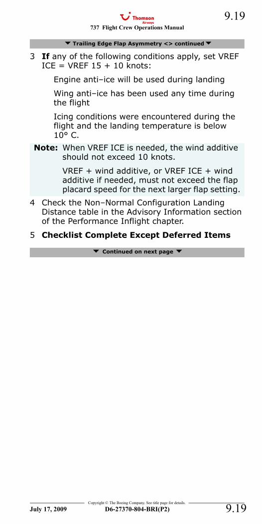
737 Flight Crew Operations Manual 9.19
Copyright © The Boeing Company. See title page for details.
D6-27370-804-BRI(P2) 9.19
3 If any of the following conditions apply, set VREF ICE = VREF 15 + 10 knots:
Engine anti–ice will be used during landing
Wing anti–ice has been used any time during the flight
Icing conditions were encountered during the flight and the landing temperature is below10° C.
4 Check the Non–Normal Configuration Landing Distance table in the Advisory Information section of the Performance Inflight chapter.
5 Checklist Complete Except Deferred Items
Continued on next page
Trailing Edge Flap Asymmetry <> continued
Note: When VREF ICE is needed, the wind additive should not exceed 10 knots.
VREF + wind additive, or VREF ICE + wind additive if needed, must not exceed the flap placard speed for the next larger flap setting.
July 17, 2009
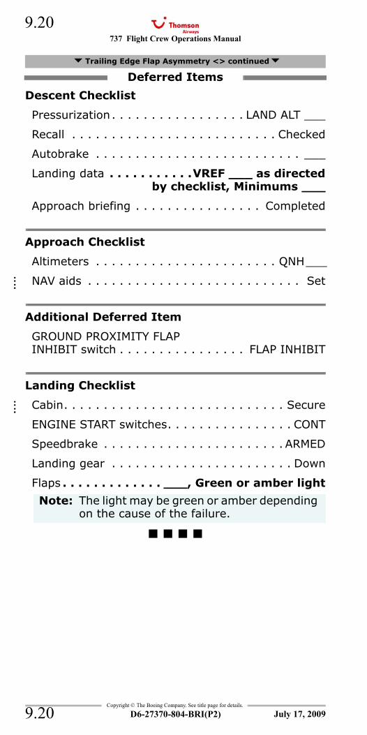
737 Flight Crew Operations Manual
Copyright © The Boeing Company. See title page for details.
D6-27370-804-BRI(P2)
9.20
9.20
Descent Checklist
Pressurization. . . . . . . . . . . . . . . . . LAND ALT ___
Recall . . . . . . . . . . . . . . . . . . . . . . . . . . Checked
Autobrake . . . . . . . . . . . . . . . . . . . . . . . . . . ___
Landing data . . . . . . . . . . .VREF ___ as directedby checklist, Minimums ___
Approach briefing . . . . . . . . . . . . . . . . Completed
Approach Checklist
Altimeters . . . . . . . . . . . . . . . . . . . . . . . QNH___
NAV aids . . . . . . . . . . . . . . . . . . . . . . . . . . . Set
Additional Deferred Item
GROUND PROXIMITY FLAPINHIBIT switch . . . . . . . . . . . . . . . . FLAP INHIBIT
Landing Checklist
Cabin. . . . . . . . . . . . . . . . . . . . . . . . . . . . Secure
ENGINE START switches. . . . . . . . . . . . . . . . CONT
Speedbrake . . . . . . . . . . . . . . . . . . . . . . . ARMED
Landing gear . . . . . . . . . . . . . . . . . . . . . . . Down
Flaps . . . . . . . . . . . . . ___, Green or amber light
Trailing Edge Flap Asymmetry <> continued
Deferred Items
Note: The light may be green or amber depending on the cause of the failure.
July 17, 2009
::::
::::
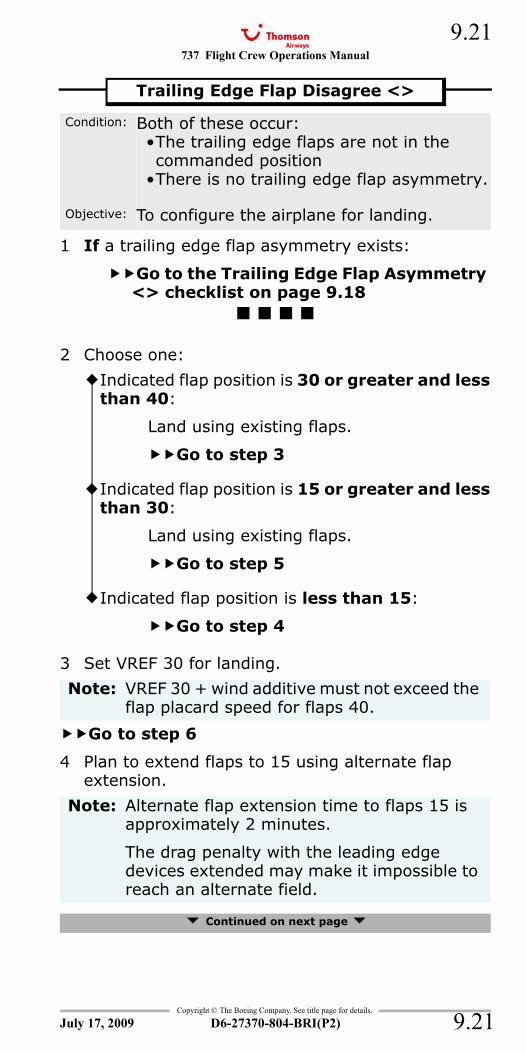
737 Flight Crew Operations Manual 9.21
Copyright © The Boeing Company. See title page for details.
D6-27370-804-BRI(P2) 9.21
1 If a trailing edge flap asymmetry exists:
Go to the Trailing Edge Flap Asymmetry <> checklist on page 9.18
2 Choose one:
3 Set VREF 30 for landing.
Go to step 6
4 Plan to extend flaps to 15 using alternate flap extension.
Continued on next page
Trailing Edge Flap Disagree <>
Condition: Both of these occur:•The trailing edge flaps are not in the commanded position
•There is no trailing edge flap asymmetry.
Objective: To configure the airplane for landing.
Indicated flap position is 30 or greater and less than 40:
Land using existing flaps.
Go to step 3
Indicated flap position is 15 or greater and less than 30:
Land using existing flaps.
Go to step 5
Indicated flap position is less than 15:
Go to step 4
Note: VREF 30 + wind additive must not exceed the flap placard speed for flaps 40.
Note: Alternate flap extension time to flaps 15 is approximately 2 minutes.
The drag penalty with the leading edge devices extended may make it impossible to reach an alternate field.
July 17, 2009
737 Flight Crew Operations Manual
Copyright © The Boeing Company. See title page for details.
D6-27370-804-BRI(P2)
9.22
9.22
5 Set VREF 15 or VREF ICE for landing.
If any of the following conditions apply, set VREF ICE = VREF 15 + 10 knots:
Engine anti–ice will be used during landing
Wing anti–ice has been used any time during the flight
Icing conditions were encountered during the flight and the landing temperature is below 10° C.
6 Check the Non–Normal Configuration Landing Distance table in the Advisory Information section of the Performance Inflight chapter.
7 Checklist Complete Except Deferred Items
Descent Checklist
Pressurization. . . . . . . . . . . . . . . . . LAND ALT ___
Recall . . . . . . . . . . . . . . . . . . . . . . . . . . Checked
Autobrake . . . . . . . . . . . . . . . . . . . . . . . . . . ___
Landing data . . . . . . . . . . .VREF ___ as directedby checklist, Minimums ___
Approach briefing . . . . . . . . . . . . . . . . Completed
Approach Checklist
Altimeters . . . . . . . . . . . . . . . . . . . . . . . QNH___
NAV aids . . . . . . . . . . . . . . . . . . . . . . . . . . . Set
Continued on next page
Trailing Edge Flap Disagree <> continued
Note: When VREF ICE is needed, the wind additive should not exceed 10 knots.
VREF 15 + wind additive, or VREF ICE + wind additive if needed, must not exceed the flap placard speed for the next larger flap setting.
Deferred Items
July 17, 2009
::::
737 Flight Crew Operations Manual 9.23
Copyright © The Boeing Company. See title page for details.
D6-27370-804-BRI(P2) 9.23
Additional Deferred Item
Choose one:
Continued on next page
Trailing Edge Flap Disagree <> continued
Indicated flap position is 30 or greater:
Go to Landing Checklist below
Indicated flap position is 15 or greater and less than 30:
GROUND PROXIMITY FLAPINHIBIT switch . . . . . . . . . .FLAP INHIBIT
Go to Landing Checklist below
Indicated flap position is less than 15:
GROUND PROXIMITY FLAPINHIBIT switch . . . . . . . . . .FLAP INHIBIT
Go to Alternate Flap Extension below
July 17, 2009
737 Flight Crew Operations Manual
Copyright © The Boeing Company. See title page for details.
D6-27370-804-BRI(P2)
9.24
9.24
Alternate Flap Extension
During flap extension, set the flap lever to the desired flap position.
G-FDZA - G-FDZS
G-CDZH - G-CDZM
As flaps are extending, slow to respective maneuvering speed.
Continued on next page
Trailing Edge Flap Disagree <> continued
230K maximum during alternate flap extension.ALTERNATE FLAPS master switch . . . . . . . ARM
Note: The landing gear configuration warning may sound if the flaps are between 10 and 15 and the landing gear are retracted.
Note: The amber LE FLAPS TRANSIT light will stay illuminated until the flaps approach the flaps 15 position.
Note: The amber LE FLAPS TRANSIT light will stay illuminated until the flaps approach the flaps 10 position.
Note: Operation within the lower amber airspeed band may be needed until the LE FLAPS TRANSIT light extinguishes.
If flap asymmetry occurs, release the switch immediately. There is no asymmetry protection.ALTERNATE FLAPS position switch . . . . . . . . . . . . . . .Hold DOWN
to extend flapsto 15 on schedule
July 17, 2009
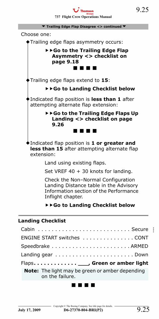
737 Flight Crew Operations Manual 9.25
Copyright © The Boeing Company. See title page for details.
D6-27370-804-BRI(P2) 9.25
Choose one:
Landing Checklist
Cabin . . . . . . . . . . . . . . . . . . . . . . . . . . . Secure
ENGINE START switches . . . . . . . . . . . . . . . CONT
Speedbrake . . . . . . . . . . . . . . . . . . . . . . . ARMED
Landing gear . . . . . . . . . . . . . . . . . . . . . . . Down
Flaps. . . . . . . . . . . . . ___, Green or amber light
Trailing Edge Flap Disagree <> continued
Trailing edge flaps asymmetry occurs:
Go to the Trailing Edge Flap Asymmetry <> checklist on page 9.18
Trailing edge flaps extend to 15:
Go to Landing Checklist below
Indicated flap position is less than 1 after attempting alternate flap extension:
Go to the Trailing Edge Flaps Up Landing <> checklist on page 9.26
Indicated flap position is 1 or greater and less than 15 after attempting alternate flap extension:
Land using existing flaps.
Set VREF 40 + 30 knots for landing.
Check the Non–Normal Configuration Landing Distance table in the Advisory Information section of the Performance Inflight chapter.
Go to Landing Checklist below
Note: The light may be green or amber depending on the failure.
July 17, 2009
::::
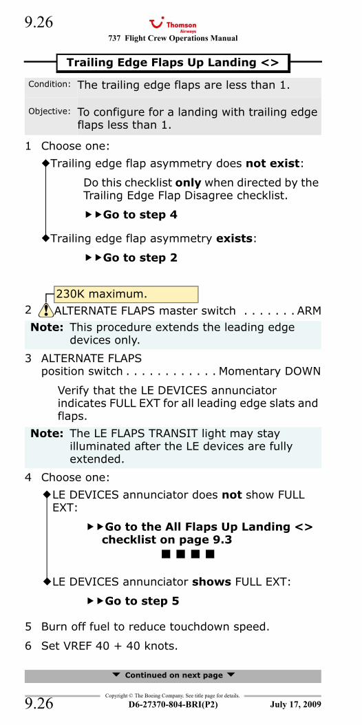
737 Flight Crew Operations Manual
Copyright © The Boeing Company. See title page for details.
D6-27370-804-BRI(P2)
9.26
9.26
1 Choose one:
3 ALTERNATE FLAPS position switch . . . . . . . . . . . . Momentary DOWN
Verify that the LE DEVICES annunciator indicates FULL EXT for all leading edge slats and flaps.
4 Choose one:
5 Burn off fuel to reduce touchdown speed.
6 Set VREF 40 + 40 knots.
Continued on next page
Trailing Edge Flaps Up Landing <>
Condition: The trailing edge flaps are less than 1.
Objective: To configure for a landing with trailing edge flaps less than 1.
Trailing edge flap asymmetry does not exist:
Do this checklist only when directed by the Trailing Edge Flap Disagree checklist.
Go to step 4
Trailing edge flap asymmetry exists:
Go to step 2
230K maximum.2 ALTERNATE FLAPS master switch . . . . . . . ARMNote: This procedure extends the leading edge
devices only.
Note: The LE FLAPS TRANSIT light may stay illuminated after the LE devices are fully extended.
LE DEVICES annunciator does not show FULL EXT:
Go to the All Flaps Up Landing <> checklist on page 9.3
LE DEVICES annunciator shows FULL EXT:
Go to step 5
July 17, 2009
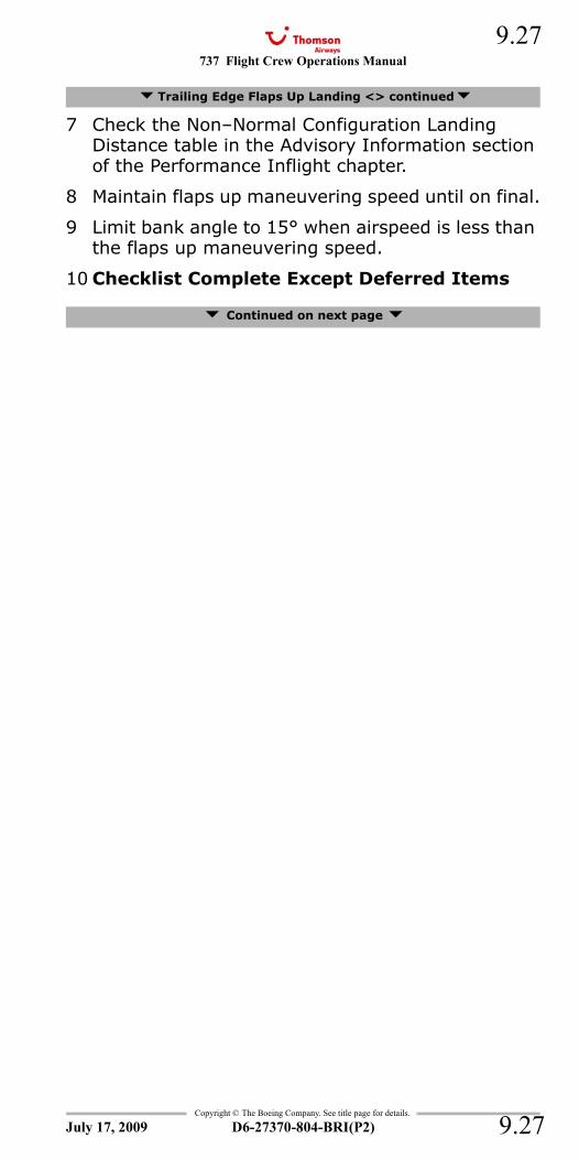
737 Flight Crew Operations Manual 9.27
Copyright © The Boeing Company. See title page for details.
D6-27370-804-BRI(P2) 9.27
7 Check the Non–Normal Configuration Landing Distance table in the Advisory Information section of the Performance Inflight chapter.
8 Maintain flaps up maneuvering speed until on final.
9 Limit bank angle to 15° when airspeed is less than the flaps up maneuvering speed.
10 Checklist Complete Except Deferred Items
Continued on next page
Trailing Edge Flaps Up Landing <> continued
July 17, 2009
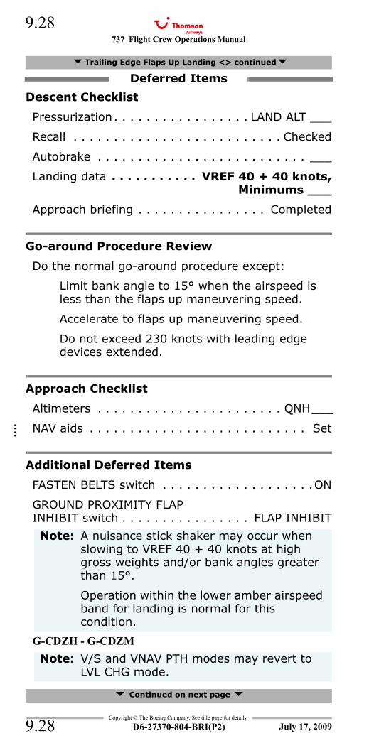
737 Flight Crew Operations Manual
Copyright © The Boeing Company. See title page for details.
D6-27370-804-BRI(P2)
9.28
9.28
Descent Checklist
Pressurization. . . . . . . . . . . . . . . . . LAND ALT ___
Recall . . . . . . . . . . . . . . . . . . . . . . . . . . Checked
Autobrake . . . . . . . . . . . . . . . . . . . . . . . . . . ___
Landing data . . . . . . . . . . . VREF 40 + 40 knots, Minimums ___
Approach briefing . . . . . . . . . . . . . . . . Completed
Go-around Procedure Review
Do the normal go-around procedure except:
Limit bank angle to 15° when the airspeed is less than the flaps up maneuvering speed.
Accelerate to flaps up maneuvering speed.
Do not exceed 230 knots with leading edge devices extended.
Approach Checklist
Altimeters . . . . . . . . . . . . . . . . . . . . . . . QNH___
NAV aids . . . . . . . . . . . . . . . . . . . . . . . . . . . Set
Additional Deferred Items
FASTEN BELTS switch . . . . . . . . . . . . . . . . . . .ON
GROUND PROXIMITY FLAPINHIBIT switch . . . . . . . . . . . . . . . . FLAP INHIBIT
G-CDZH - G-CDZM
Continued on next page
Trailing Edge Flaps Up Landing <> continued
Deferred Items
Note: A nuisance stick shaker may occur when slowing to VREF 40 + 40 knots at high gross weights and/or bank angles greater than 15°.
Operation within the lower amber airspeed band for landing is normal for this condition.
Note: V/S and VNAV PTH modes may revert to LVL CHG mode.
July 17, 2009
::::
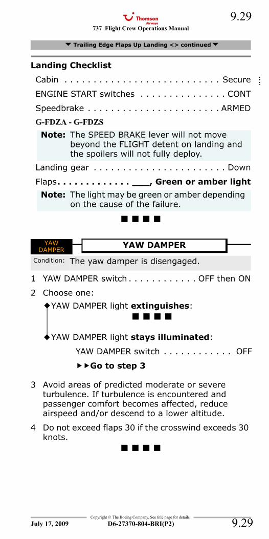
737 Flight Crew Operations Manual 9.29
Copyright © The Boeing Company. See title page for details.
D6-27370-804-BRI(P2) 9.29
Landing Checklist
Cabin . . . . . . . . . . . . . . . . . . . . . . . . . . . Secure
ENGINE START switches . . . . . . . . . . . . . . . CONT
Speedbrake . . . . . . . . . . . . . . . . . . . . . . . ARMED
G-FDZA - G-FDZS
Landing gear . . . . . . . . . . . . . . . . . . . . . . . Down
Flaps. . . . . . . . . . . . . ___, Green or amber light
YAW DAMPER
1 YAW DAMPER switch . . . . . . . . . . . . OFF then ON
2 Choose one:
3 Avoid areas of predicted moderate or severe turbulence. If turbulence is encountered and passenger comfort becomes affected, reduce airspeed and/or descend to a lower altitude.
4 Do not exceed flaps 30 if the crosswind exceeds 30 knots.
Trailing Edge Flaps Up Landing <> continued
Note: The SPEED BRAKE lever will not move beyond the FLIGHT detent on landing and the spoilers will not fully deploy.
Note: The light may be green or amber depending on the cause of the failure.
YAWDAMPER
YAW DAMPER
Condition: The yaw damper is disengaged.
YAW DAMPER light extinguishes:
YAW DAMPER light stays illuminated:
YAW DAMPER switch . . . . . . . . . . . . OFF
Go to step 3
July 17, 2009
::::
737 Flight Crew Operations Manual
Copyright © The Boeing Company. See title page for details.
D6-27370-804-BRI(P2)
9.30
9.30
IntentionallyBlank
July 17, 2009
737 Flight Crew Operations Manual
Non-Normal Checklists Chapter NNCFlight Instruments, Displays Section 10
Table of Contents
Copyright © The Boeing Company. See title page for details.
D6-27370-804-BRI(P2) 10.TOC.1
Airspeed Unreliable.....................................10.1
Airspeed Unreliable.....................................10.1ALT DISAGREE...............................................10.2AOA DISAGREE..............................................10.2CDS FAULT....................................................10.3Display Failure ...............................................10.3DISPLAYS CONTROL PANEL .............................10.4DISPLAY SOURCE...........................................10.4FLIGHT RECORDER OFF ..................................10.5IAS DISAGREE...............................................10.5
July 17, 2009
NNC.10-Flight Instruments, DisplaysTable Of Contents

737 Flight Crew Operations Manual
Non-Normal Checklists -Flight Instruments, Displays
Table of Contents
Copyright © The Boeing Company. See title page for details.
D6-27370-804-BRI(P2)10.TOC.2
IntentionallyBlank
July 17, 2009
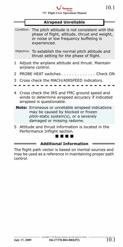
737 Flight Crew Operations Manual 10.1
Copyright © The Boeing Company. See title page for details.
D6-27370-804-BRI(P2) 10.1
NNC.10 Non-Normal Checklists-Flight Instruments, Displays
1 Adjust the airplane attitude and thrust. Maintain airplane control.
2 PROBE HEAT switches . . . . . . . . . . . . . Check ON
3 Cross check the MACH/AIRSPEED indicators.- - - - - - - - - - - - - - - - - - - - - - -4 Cross check the IRS and FMC ground speed and
winds to determine airspeed accuracy if indicated airspeed is questionable.
5 Attitude and thrust information is located in the Performance Inflight section.
The flight path vector is based on inertial sources and may be used as a reference in maintaining proper path control.
Airspeed Unreliable
Condition: The pitch attitude is not consistent with the phase of flight, altitude, thrust and weight, or noise or low frequency buffeting is experienced.
Objective: To establish the normal pitch attitude and thrust setting for the phase of flight.
Note: Erroneous or unreliable airspeed indications may be caused by blocked or frozen pitot-static system(s), or a severely damaged or missing radome.
Additional Information
July 17, 2009
737 Flight Crew Operations Manual
Copyright © The Boeing Company. See title page for details.
D6-27370-804-BRI(P2)
10.2
10.2
ALT DISAGREE
1 Check all altimeters are set to correct barometric setting for phase of flight.
2 Choose one:
3 Airplane does not meet RVSM airspace requirements.
4 Standby altimeter is available.
5 Transponder altitude received by ATC may be unreliable.
6 Maintain visual conditions if possible.
7 Establish landing configuration early.
8 Radio altitude reference is available below 2,500 feet.
9 Use electronic and visual glide slope indicators, where available, for approach and landing.
AOA DISAGREE
G-FDZA - G-FDZS
1 Airspeed errors and the IAS DISAGREE alert may occur.
2 Altimeter errors and the ALT DISAGREE alert may occur.
ALT DISAGREE
Condition: The ALT DISAGREE alert indicates the captain’s and first officer’s altitude indications disagree by more than 200 feet.
ALT DISAGREE alert extinguishes:
Continue normal operation.
ALT DISAGREE alert stays illuminated:
Go to step 3
AOA DISAGREE
Condition: The AOA DISAGREE alert indicates the left and right angle of attack vanes disagree.
July 17, 2009
737 Flight Crew Operations Manual 10.3
Copyright © The Boeing Company. See title page for details.
D6-27370-804-BRI(P2) 10.3
CDS FAULT
1 Do not takeoff.
1 Choose one:
2 MAIN PANEL DUs selector . . . . . . . . . .As needed
3 LOWER DU selector . . . . . . . . . . . . . .As needed
CDS FAULT
Condition: The CDS FAULT annunciation indicates a CDS fault occurs.
Note: CDS FAULT annunciates on the ground only, before the second engine start.
Display Failure
Condition: A display in the common display system is failed.
A single display is not usable and automatic switching has occurred:
Continue normal operation.
A single display is not usable and automatic switching has not occurred:
Go to step 2
July 17, 2009
737 Flight Crew Operations Manual
Copyright © The Boeing Company. See title page for details.
D6-27370-804-BRI(P2)
10.4
10.4
DISPLAYS CONTROL PANEL
1 CONTROL PANEL selectswitch . . . . . . . . . . . . .BOTH ON 1 or BOTH ON 2
Select the operating control panel.
2 Verify that the DISPLAYS CONTROL PANEL annunciation and ALT flag extinguish.
DSPLY SOURCE
1 If the DEU fails on the same side as the engaged autopilot:
Select the opposite autopilot.
Verify that the correct flight director indications and flight mode annunciations are shown on the same side as the operating autopilot.
2 If the EEC ALTN lights are illuminated and the EEC ALTERNATE MODE checklist has not been completed:
Go to the EEC ALTERNATE MODE checklist on page 7.9
DISPLAYS CONTROL PANEL
Condition: The DISPLAYS CONTROL PANEL annunciation indicates the EFIS control panel is failed.
Note: The altimeter blanks and an ALT flag illuminates on the side corresponding to the failed control panel.
DISPLAY SOURCE
Condition: The DSPLY SOURCE annunciation indicates only one DEU is supplying display information. Indications may include:•No hydraulic pressure indication on the failed side
•Speed limit flag shown on the failed side•Minimum maneuver speed and stick shaker band removed on the failed side
•Both EEC ALTN lights illuminated.
Note: Flight director indications may be removed and autoflight mode reversions may occur.
Dual autopilot approach is not available.
July 17, 2009
737 Flight Crew Operations Manual 10.5
Copyright © The Boeing Company. See title page for details.
D6-27370-804-BRI(P2) 10.5
OFF - Flight Recorder
1 Continue normal operation.
IAS DISAGREE
Go to the Airspeed Unreliable checklist on page 10.1
OFF FLIGHT RECORDER OFF
Condition: The flight recorder is off.
IAS DISAGREE
Condition: The IAS DISAGREE alert indicates the captain’s and first officer’s airspeed indications disagree.
July 17, 2009

737 Flight Crew Operations Manual
Copyright © The Boeing Company. See title page for details.
D6-27370-804-BRI(P2)
10.6
10.6
IntentionallyBlank
July 17, 2009
737 Flight Crew Operations Manual
Non-Normal Checklists Chapter NNCFlight Management, Navigation Section 11
Table of Contents
Copyright © The Boeing Company. See title page for details.
D6-27370-804-BRI(P2) 11.TOC.1
FMC DISAGREE..............................................11.1FMC FAIL ......................................................11.2FMC/CDU ALERTING MESSAGE.........................11.3GLS..............................................................11.3GPS..............................................................11.4ILS...............................................................11.4IRS DC FAIL ..................................................11.4IRS FAULT.....................................................11.6IRS FAULT................................................... 11.10IRS ON DC .................................................. 11.12UNABLE REQD NAV PERF - RNP...................... 11.13
July 17, 2009
NNC.11-Flight Management, NavigationTable Of Contents
737 Flight Crew Operations Manual
Non-Normal Checklists -Flight Management, Navigation
Table of Contents
Copyright © The Boeing Company. See title page for details.
D6-27370-804-BRI(P2)11.TOC.2
IntentionallyBlank
July 17, 2009
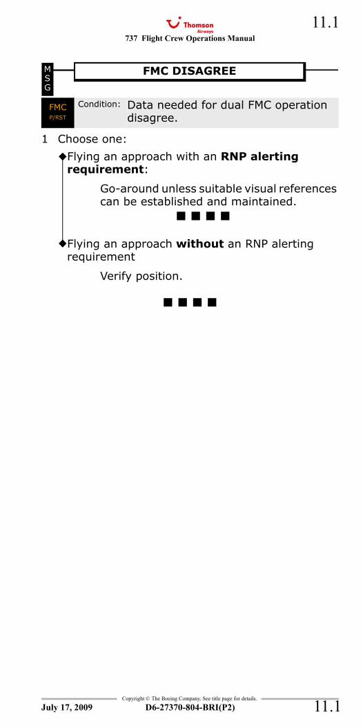
737 Flight Crew Operations Manual 11.1
Copyright © The Boeing Company. See title page for details.
D6-27370-804-BRI(P2) 11.1
NNC.11 Non-Normal Checklists-Flight Management, NavigationMSG and FMC - FMC DISAGREEFMC and MSG - FMC DISAGREEFMC - FMC DISAGREEFMC DISAGREE
1 Choose one:
MSG
FMC DISAGREE
FMC P/RST
Condition: Data needed for dual FMC operation disagree.
Flying an approach with an RNP alerting requirement:
Go-around unless suitable visual references can be established and maintained.
Flying an approach without an RNP alerting requirement
Verify position.
July 17, 2009
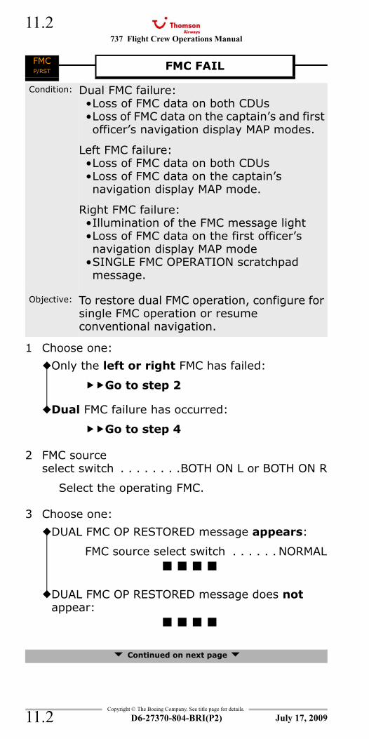
737 Flight Crew Operations Manual
Copyright © The Boeing Company. See title page for details.
D6-27370-804-BRI(P2)
11.2
11.2
FMC - FMC FAIL (With Dual FMC Option)
1 Choose one:
2 FMC sourceselect switch . . . . . . . .BOTH ON L or BOTH ON R
Select the operating FMC.
3 Choose one:
Continued on next page
FMC P/RST FMC FAIL
Condition: Dual FMC failure: •Loss of FMC data on both CDUs•Loss of FMC data on the captain’s and first officer’s navigation display MAP modes.
Left FMC failure:•Loss of FMC data on both CDUs•Loss of FMC data on the captain’s navigation display MAP mode.
Right FMC failure:•Illumination of the FMC message light•Loss of FMC data on the first officer’s navigation display MAP mode
•SINGLE FMC OPERATION scratchpad message.
Objective: To restore dual FMC operation, configure for single FMC operation or resume conventional navigation.
Only the left or right FMC has failed:
Go to step 2
Dual FMC failure has occurred:
Go to step 4
DUAL FMC OP RESTORED message appears:
FMC source select switch . . . . . . NORMAL
DUAL FMC OP RESTORED message does not appear:
July 17, 2009
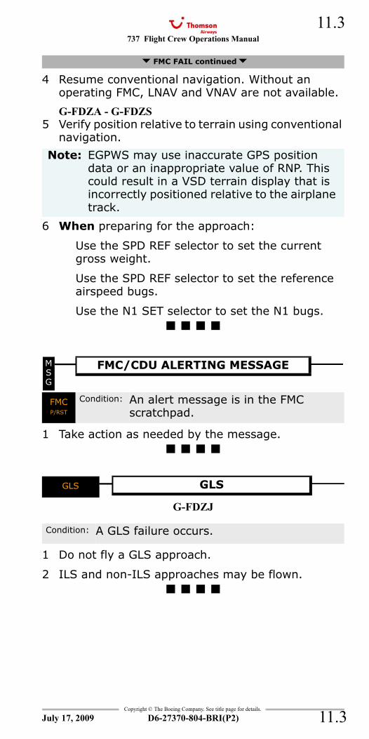
737 Flight Crew Operations Manual 11.3
Copyright © The Boeing Company. See title page for details.
D6-27370-804-BRI(P2) 11.3
4 Resume conventional navigation. Without an operating FMC, LNAV and VNAV are not available.
G-FDZA - G-FDZS5 Verify position relative to terrain using conventional
navigation.
6 When preparing for the approach:
Use the SPD REF selector to set the current gross weight.
Use the SPD REF selector to set the reference airspeed bugs.
Use the N1 SET selector to set the N1 bugs.
MSG and FMC - CDU AlertingFMC and MSG - CDU AlertingFMC - CDU Alerting
1 Take action as needed by the message.
GLS
G-FDZJ
1 Do not fly a GLS approach.
2 ILS and non-ILS approaches may be flown.
FMC FAIL continued
Note: EGPWS may use inaccurate GPS position data or an inappropriate value of RNP. This could result in a VSD terrain display that is incorrectly positioned relative to the airplane track.
MSG
FMC/CDU ALERTING MESSAGE
FMC P/RST
Condition: An alert message is in the FMC scratchpad.
GLS GLS
Condition: A GLS failure occurs.
July 17, 2009
737 Flight Crew Operations Manual
Copyright © The Boeing Company. See title page for details.
D6-27370-804-BRI(P2)
11.4
11.4
GPS
1 Continue normal operation if ANP meets the requirements for the phase of flight.
ILS
G-FDZJ
1 Do not fly an ILS approach.
2 GLS and non-ILS approaches may be flown.
DC FAIL
1 If all other IRS lights are extinguished:
Continue normal operation.
GPS GPS
Condition: One or both GPS receivers are failed.
Note: The FMC uses only IRS or radio inputs.
Look-ahead terrain alerting and display are unavailable due to position uncertainty.
ILS ILS
Condition: An ILS failure occurs.
DC FAIL IRS DC FAIL
Condition: IRS backup DC power is failed.
Note: With both IRS DC FAIL lights illuminated, the switched hot battery bus is not powered or the battery is nearly discharged.
July 17, 2009
737 Flight Crew Operations Manual 11.5
Copyright © The Boeing Company. See title page for details.
D6-27370-804-BRI(P2) 11.5
IntentionallyBlank
July 17, 2009
737 Flight Crew Operations Manual
Copyright © The Boeing Company. See title page for details.
D6-27370-804-BRI(P2)
11.6
11.6
FAULT - IRSALIGN and FAULT - IRSFAULT and ALIGN - IRS
G-FDZA - G-FDZS
1 Choose one:
On the ground
2 Choose one:
3 After the ALIGN light extinguishes:
IRS mode selector . . . . . . . . . . . . . . . . . NAV
Enter present position.
Continued on next page
FAULT IRS FAULT
Condition: One or more of these occur:•An IRS fault occurs•On the ground, if the ALIGN light is also illuminated, the present position entry is possibly incorrect.
On the ground:
Go to step 2
In flight:
Go to step 6
ALIGN light is extinguished:
Notify maintenance.
ALIGN light is also illuminated:
IRS mode selector . . . . . . . . . . . . . . OFF
The FAULT light extinguishes immediately and the ALIGN light extinguishes after approximately 30 seconds.
Go to step 3
July 17, 2009
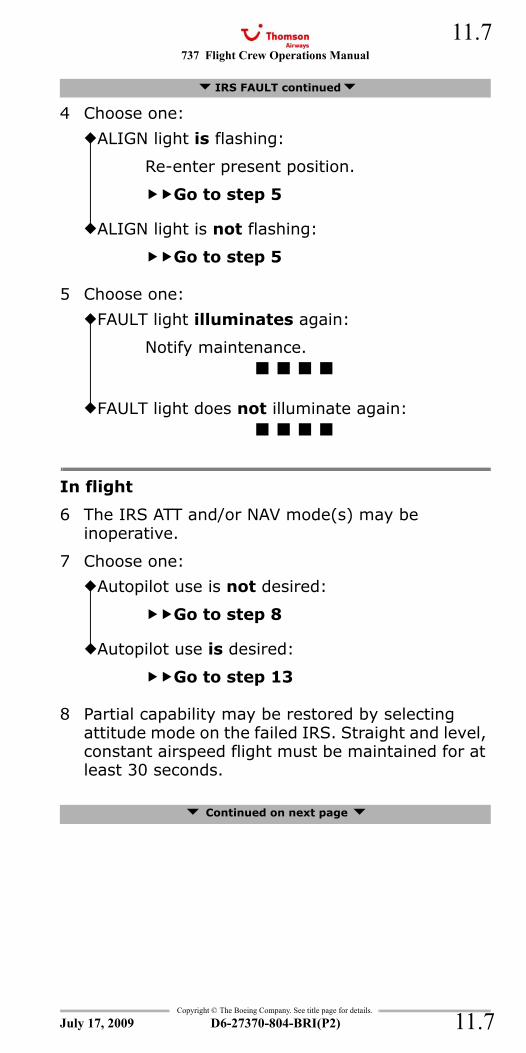
737 Flight Crew Operations Manual 11.7
Copyright © The Boeing Company. See title page for details.
D6-27370-804-BRI(P2) 11.7
4 Choose one:
5 Choose one:
In flight
6 The IRS ATT and/or NAV mode(s) may be inoperative.
7 Choose one:
8 Partial capability may be restored by selecting attitude mode on the failed IRS. Straight and level, constant airspeed flight must be maintained for at least 30 seconds.
Continued on next page
IRS FAULT continued
ALIGN light is flashing:
Re-enter present position.
Go to step 5
ALIGN light is not flashing:
Go to step 5
FAULT light illuminates again:
Notify maintenance.
FAULT light does not illuminate again:
Autopilot use is not desired:
Go to step 8
Autopilot use is desired:
Go to step 13
July 17, 2009
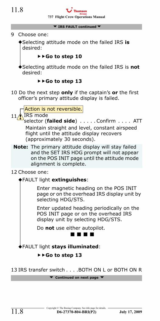
737 Flight Crew Operations Manual
Copyright © The Boeing Company. See title page for details.
D6-27370-804-BRI(P2)
11.8
11.8
9 Choose one:
10 Do the next step only if the captain’s or the first officer’s primary attitude display is failed.
Maintain straight and level, constant airspeed flight until the attitude display recovers (approximately 30 seconds).
12 Choose one:
13 IRS transfer switch . . . .BOTH ON L or BOTH ON R Continued on next page
IRS FAULT continued
Selecting attitude mode on the failed IRS is desired:
Go to step 10
Selecting attitude mode on the failed IRS is not desired:
Go to step 13
Action is not reversible.11 IRS mode
selector (failed side) . . . . . Confirm . . . . ATT
Note: The primary attitude display will stay failed and the SET IRS HDG prompt will not appear on the POS INIT page until the attitude mode alignment is complete.
FAULT light extinguishes:
Enter magnetic heading on the POS INIT page or on the overhead IRS display unit by selecting HDG/STS.
Enter updated heading periodically on the POS INIT page or on the overhead IRS display unit by selecting HDG/STS.
Do not use either autopilot.
FAULT light stays illuminated:
Go to step 13
July 17, 2009
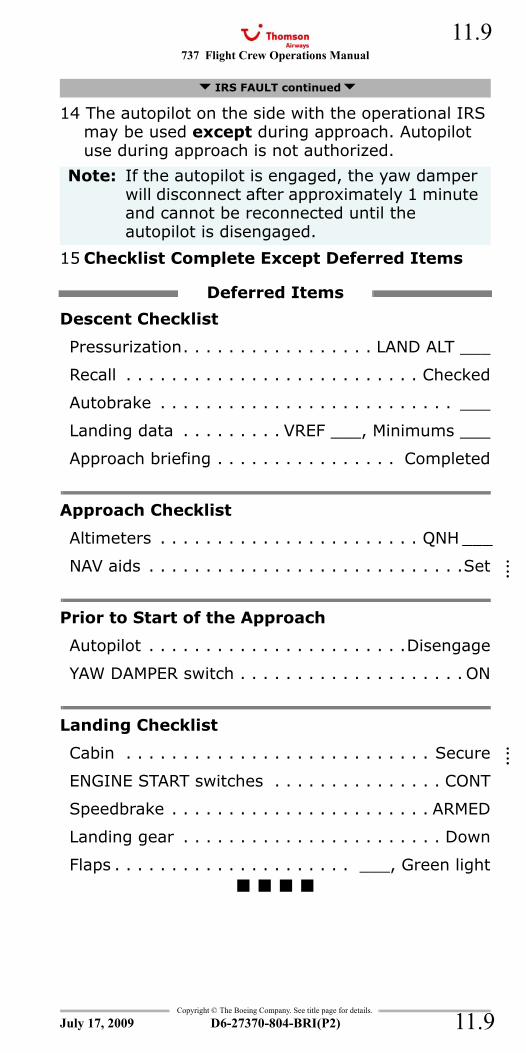
737 Flight Crew Operations Manual 11.9
Copyright © The Boeing Company. See title page for details.
D6-27370-804-BRI(P2) 11.9
14 The autopilot on the side with the operational IRS may be used except during approach. Autopilot use during approach is not authorized.
15 Checklist Complete Except Deferred Items
Descent Checklist
Pressurization. . . . . . . . . . . . . . . . . LAND ALT ___
Recall . . . . . . . . . . . . . . . . . . . . . . . . . . Checked
Autobrake . . . . . . . . . . . . . . . . . . . . . . . . . . ___
Landing data . . . . . . . . . VREF ___, Minimums ___
Approach briefing . . . . . . . . . . . . . . . . Completed
Approach Checklist
Altimeters . . . . . . . . . . . . . . . . . . . . . . . QNH ___
NAV aids . . . . . . . . . . . . . . . . . . . . . . . . . . . .Set
Prior to Start of the Approach
Autopilot . . . . . . . . . . . . . . . . . . . . . . .Disengage
YAW DAMPER switch . . . . . . . . . . . . . . . . . . . . ON
Landing Checklist
Cabin . . . . . . . . . . . . . . . . . . . . . . . . . . . Secure
ENGINE START switches . . . . . . . . . . . . . . . CONT
Speedbrake . . . . . . . . . . . . . . . . . . . . . . . ARMED
Landing gear . . . . . . . . . . . . . . . . . . . . . . . Down
Flaps . . . . . . . . . . . . . . . . . . . . . ___, Green light
IRS FAULT continued
Note: If the autopilot is engaged, the yaw damper will disconnect after approximately 1 minute and cannot be reconnected until the autopilot is disengaged.
Deferred Items
July 17, 2009
::::
::::
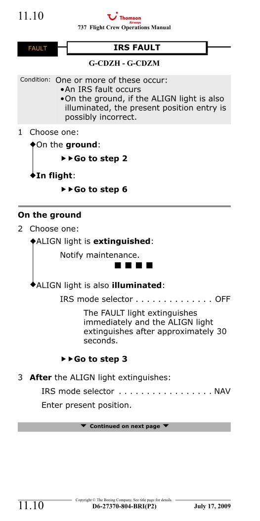
737 Flight Crew Operations Manual
Copyright © The Boeing Company. See title page for details.
D6-27370-804-BRI(P2)
11.10
11.10
FAULT - IRSALIGN and FAULT - IRSFAULT and ALIGN - IRS
G-CDZH - G-CDZM
1 Choose one:
On the ground
2 Choose one:
3 After the ALIGN light extinguishes:
IRS mode selector . . . . . . . . . . . . . . . . . NAV
Enter present position.
Continued on next page
FAULT IRS FAULT
Condition: One or more of these occur:•An IRS fault occurs•On the ground, if the ALIGN light is also illuminated, the present position entry is possibly incorrect.
On the ground:
Go to step 2
In flight:
Go to step 6
ALIGN light is extinguished:
Notify maintenance.
ALIGN light is also illuminated:
IRS mode selector . . . . . . . . . . . . . . OFF
The FAULT light extinguishes immediately and the ALIGN light extinguishes after approximately 30 seconds.
Go to step 3
July 17, 2009
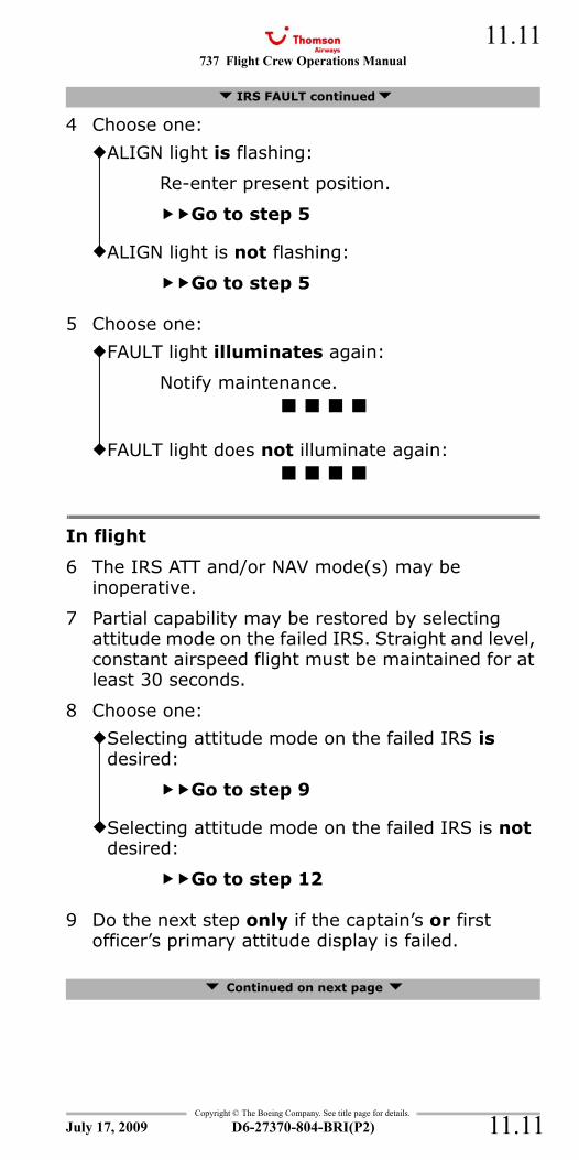
737 Flight Crew Operations Manual 11.11
Copyright © The Boeing Company. See title page for details.
D6-27370-804-BRI(P2) 11.11
4 Choose one:
5 Choose one:
In flight
6 The IRS ATT and/or NAV mode(s) may be inoperative.
7 Partial capability may be restored by selecting attitude mode on the failed IRS. Straight and level, constant airspeed flight must be maintained for at least 30 seconds.
8 Choose one:
9 Do the next step only if the captain’s or first officer’s primary attitude display is failed.
Continued on next page
IRS FAULT continued
ALIGN light is flashing:
Re-enter present position.
Go to step 5
ALIGN light is not flashing:
Go to step 5
FAULT light illuminates again:
Notify maintenance.
FAULT light does not illuminate again:
Selecting attitude mode on the failed IRS is desired:
Go to step 9
Selecting attitude mode on the failed IRS is not desired:
Go to step 12
July 17, 2009
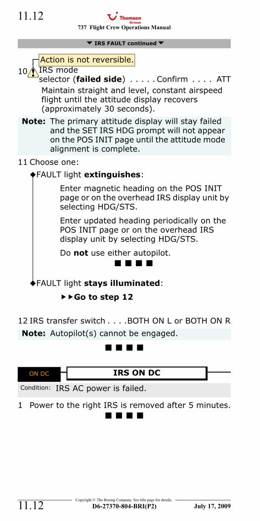
737 Flight Crew Operations Manual
Copyright © The Boeing Company. See title page for details.
D6-27370-804-BRI(P2)
11.12
11.12
Maintain straight and level, constant airspeed flight until the attitude display recovers (approximately 30 seconds).
11 Choose one:
12 IRS transfer switch . . . .BOTH ON L or BOTH ON R
ON DC
1 Power to the right IRS is removed after 5 minutes.
IRS FAULT continued
Action is not reversible.10 IRS mode
selector (failed side) . . . . . Confirm . . . . ATT
Note: The primary attitude display will stay failed and the SET IRS HDG prompt will not appear on the POS INIT page until the attitude mode alignment is complete.
FAULT light extinguishes:
Enter magnetic heading on the POS INIT page or on the overhead IRS display unit by selecting HDG/STS.
Enter updated heading periodically on the POS INIT page or on the overhead IRS display unit by selecting HDG/STS.
Do not use either autopilot.
FAULT light stays illuminated:
Go to step 12
Note: Autopilot(s) cannot be engaged.
ON DC IRS ON DC
Condition: IRS AC power is failed.
July 17, 2009
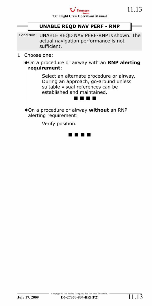
737 Flight Crew Operations Manual 11.13
Copyright © The Boeing Company. See title page for details.
D6-27370-804-BRI(P2) 11.13
UNABLE REQD NAV PERF - RNP (FMC Update U10.7 and Later)
1 Choose one:
UNABLE REQD NAV PERF - RNP
Condition: UNABLE REQD NAV PERF-RNP is shown. The actual navigation performance is not sufficient.
On a procedure or airway with an RNP alerting requirement:
Select an alternate procedure or airway. During an approach, go-around unless suitable visual references can be established and maintained.
On a procedure or airway without an RNP alerting requirement:
Verify position.
July 17, 2009

737 Flight Crew Operations Manual
Copyright © The Boeing Company. See title page for details.
D6-27370-804-BRI(P2)
11.14
11.14
IntentionallyBlank
July 17, 2009
737 Flight Crew Operations Manual
Non-Normal Checklists Chapter NNCFuel Section 12
Table of Contents
Copyright © The Boeing Company. See title page for details.
D6-27370-804-BRI(P2) 12.TOC.1
CONFIG < > All aircraft (except G-CDZM with centre tank fuel pump restrictions in force) ..............12.1
CONFIG < > G-CDZM (with centre tank fuel pump restrictions in force) ....................................12.1
CROSSFEED SELECTOR INOPERATIVE...............12.2Engine Fuel Leak............................................12.4FUEL FILTER BYPASS ......................................12.7FUEL PUMP LOW PRESSURE.............................12.8Fuel Quantity Indication Inoperative .................12.9Fuel Temperature Low ....................................12.9IMBAL ........................................................ 12.10LOW........................................................... 12.11
July 17, 2009
NNC.12-FuelTable Of Contents
737 Flight Crew Operations Manual
Non-Normal Checklists -Fuel
Table of Contents
Copyright © The Boeing Company. See title page for details.
D6-27370-804-BRI(P2)12.TOC.2
IntentionallyBlank
July 17, 2009
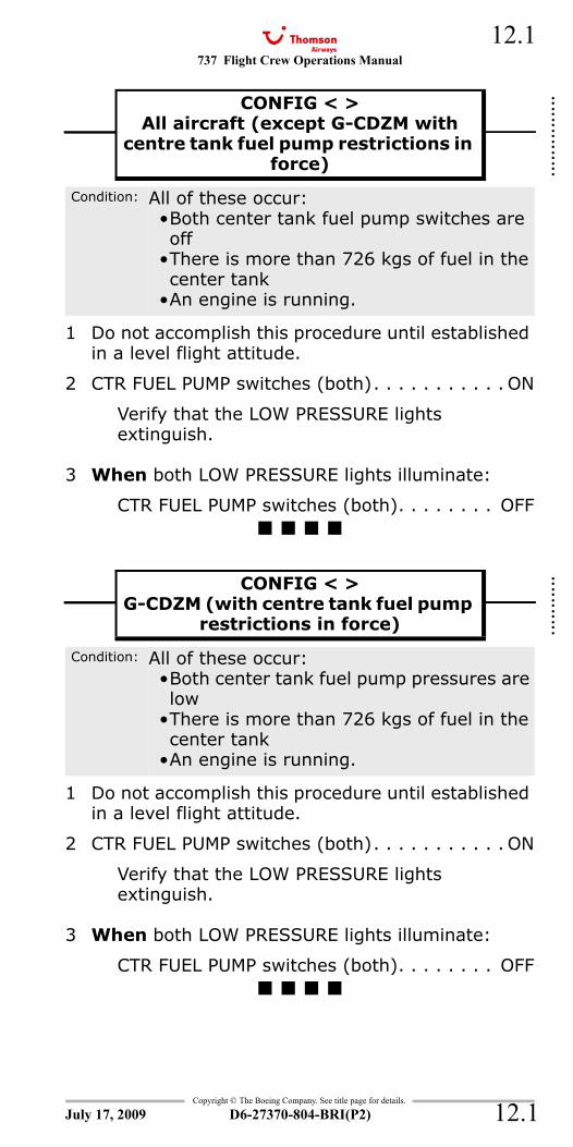
737 Flight Crew Operations Manual 12.1
Copyright © The Boeing Company. See title page for details.
D6-27370-804-BRI(P2) 12.1
NNC.12 Non-Normal Checklists-FuelCONFIG (Airplanes with Center Tank Auto Shutoff)
1 Do not accomplish this procedure until established in a level flight attitude.
2 CTR FUEL PUMP switches (both). . . . . . . . . . . ON
Verify that the LOW PRESSURE lights extinguish.
3 When both LOW PRESSURE lights illuminate:
CTR FUEL PUMP switches (both). . . . . . . . OFF
CONFIG (Airplanes without Center Tank Auto Shutoff)
1 Do not accomplish this procedure until established in a level flight attitude.
2 CTR FUEL PUMP switches (both). . . . . . . . . . . ON
Verify that the LOW PRESSURE lights extinguish.
3 When both LOW PRESSURE lights illuminate:
CTR FUEL PUMP switches (both). . . . . . . . OFF
CONFIG < >All aircraft (except G-CDZM with
centre tank fuel pump restrictions in force)
Condition: All of these occur:•Both center tank fuel pump switches are off
•There is more than 726 kgs of fuel in the center tank
•An engine is running.
CONFIG < >G-CDZM (with centre tank fuel pump
restrictions in force)
Condition: All of these occur:•Both center tank fuel pump pressures are low
•There is more than 726 kgs of fuel in the center tank
•An engine is running.
July 17, 2009
::::::::
::::::
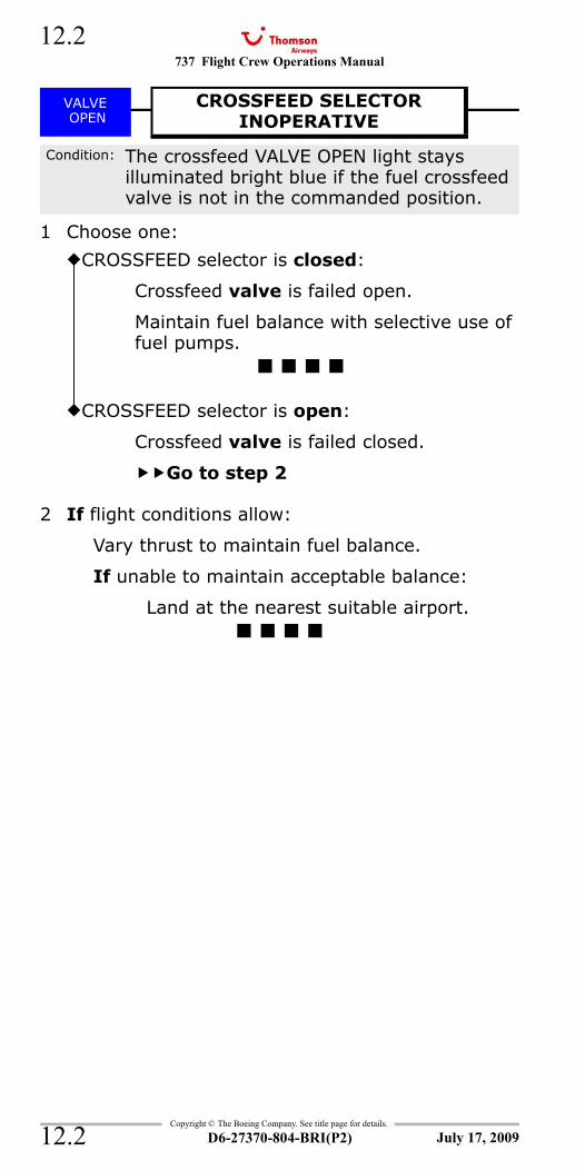
737 Flight Crew Operations Manual
Copyright © The Boeing Company. See title page for details.
D6-27370-804-BRI(P2)
12.2
12.2
VALVE OPEN - Crossfeed
1 Choose one:
2 If flight conditions allow:
Vary thrust to maintain fuel balance.
If unable to maintain acceptable balance:
Land at the nearest suitable airport.
VALVE OPEN
CROSSFEED SELECTORINOPERATIVE
Condition: The crossfeed VALVE OPEN light stays illuminated bright blue if the fuel crossfeed valve is not in the commanded position.
CROSSFEED selector is closed:
Crossfeed valve is failed open.
Maintain fuel balance with selective use of fuel pumps.
CROSSFEED selector is open:
Crossfeed valve is failed closed.
Go to step 2
July 17, 2009
737 Flight Crew Operations Manual 12.3
Copyright © The Boeing Company. See title page for details.
D6-27370-804-BRI(P2) 12.3
IntentionallyBlank
July 17, 2009
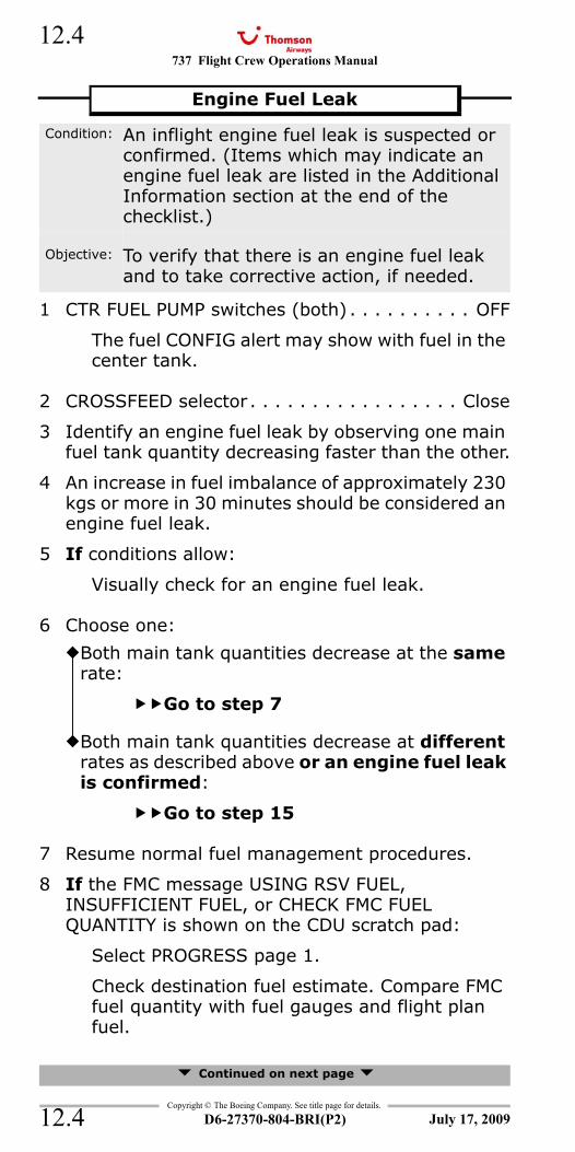
737 Flight Crew Operations Manual
Copyright © The Boeing Company. See title page for details.
D6-27370-804-BRI(P2)
12.4
12.4
1 CTR FUEL PUMP switches (both) . . . . . . . . . . OFF
The fuel CONFIG alert may show with fuel in the center tank.
2 CROSSFEED selector . . . . . . . . . . . . . . . . . Close
3 Identify an engine fuel leak by observing one main fuel tank quantity decreasing faster than the other.
4 An increase in fuel imbalance of approximately 230 kgs or more in 30 minutes should be considered an engine fuel leak.
5 If conditions allow:
Visually check for an engine fuel leak.
6 Choose one:
7 Resume normal fuel management procedures.
8 If the FMC message USING RSV FUEL, INSUFFICIENT FUEL, or CHECK FMC FUEL QUANTITY is shown on the CDU scratch pad:
Select PROGRESS page 1.
Check destination fuel estimate. Compare FMC fuel quantity with fuel gauges and flight plan fuel.
Continued on next page
Engine Fuel Leak
Condition: An inflight engine fuel leak is suspected or confirmed. (Items which may indicate an engine fuel leak are listed in the Additional Information section at the end of the checklist.)
Objective: To verify that there is an engine fuel leak and to take corrective action, if needed.
Both main tank quantities decrease at the same rate:
Go to step 7
Both main tank quantities decrease at different rates as described above or an engine fuel leak is confirmed:
Go to step 15
July 17, 2009
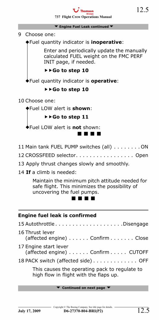
737 Flight Crew Operations Manual 12.5
Copyright © The Boeing Company. See title page for details.
D6-27370-804-BRI(P2) 12.5
9 Choose one:
10 Choose one:
11 Main tank FUEL PUMP switches (all) . . . . . . . . ON
12 CROSSFEED selector. . . . . . . . . . . . . . . . . Open
13 Apply thrust changes slowly and smoothly.
14 If a climb is needed:
Maintain the minimum pitch attitude needed for safe flight. This minimizes the possibility of uncovering the fuel pumps.
Engine fuel leak is confirmed
15 Autothrottle . . . . . . . . . . . . . . . . . . . .Disengage
16 Thrust lever(affected engine) . . . . . . Confirm . . . . . . . Close
17 Engine start lever(affected engine) . . . . . . Confirm . . . . . CUTOFF
18 PACK switch (affected side) . . . . . . . . . . . . . OFF
This causes the operating pack to regulate to high flow in flight with the flaps up.
Continued on next page
Engine Fuel Leak continued
Fuel quantity indicator is inoperative:
Enter and periodically update the manually calculated FUEL weight on the FMC PERF INIT page, if needed.
Go to step 10
Fuel quantity indicator is operative:
Go to step 10
Fuel LOW alert is shown:
Go to step 11
Fuel LOW alert is not shown:
July 17, 2009
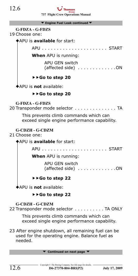
737 Flight Crew Operations Manual
Copyright © The Boeing Company. See title page for details.
D6-27370-804-BRI(P2)
12.6
12.6
G-FDZA - G-FDZS19 Choose one:
G-FDZA - G-FDZS20 Transponder mode selector . . . . . . . . . . . . . . TA
This prevents climb commands which can exceed single engine performance capability.
G-CDZH - G-CDZM21 Choose one:
G-CDZH - G-CDZM22 Transponder mode selector . . . . . . . . . . TA ONLY
This prevents climb commands which can exceed single engine performance capability.
23 After engine shutdown, all remaining fuel can be used for the operating engine. Balance fuel as needed.
Continued on next page
Engine Fuel Leak continued
APU is available for start:
APU . . . . . . . . . . . . . . . . . . . . . . START
When APU is running:
APU GEN switch(affected side) . . . . . . . . . . . . .ON
Go to step 20
APU is not available:
Go to step 20
APU is available for start:
APU . . . . . . . . . . . . . . . . . . . . . . START
When APU is running:
APU GEN switch(affected side) . . . . . . . . . . . . .ON
Go to step 22
APU is not available:
Go to step 22
July 17, 2009
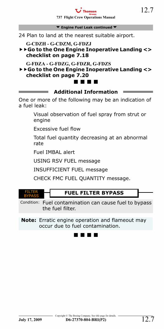
737 Flight Crew Operations Manual 12.7
Copyright © The Boeing Company. See title page for details.
D6-27370-804-BRI(P2) 12.7
24 Plan to land at the nearest suitable airport.
G-CDZH - G-CDZM, G-FDZJGo to the One Engine Inoperative Landing <> checklist on page 7.18
G-FDZA - G-FDZG, G-FDZR, G-FDZSGo to the One Engine Inoperative Landing <> checklist on page 7.20
One or more of the following may be an indication of a fuel leak:
Visual observation of fuel spray from strut or engine
Excessive fuel flow
Total fuel quantity decreasing at an abnormal rate
Fuel IMBAL alert
USING RSV FUEL message
INSUFFICIENT FUEL message
CHECK FMC FUEL QUANTITY message.
FILTER BYPASS
Engine Fuel Leak continued
Additional Information
FILTER BYPASS
FUEL FILTER BYPASS
Condition: Fuel contamination can cause fuel to bypass the fuel filter.
Note: Erratic engine operation and flameout may occur due to fuel contamination.
July 17, 2009
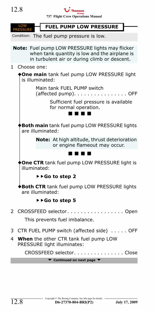
737 Flight Crew Operations Manual
Copyright © The Boeing Company. See title page for details.
D6-27370-804-BRI(P2)
12.8
12.8
LOW PRESSURE - Fuel Pump
1 Choose one:
2 CROSSFEED selector . . . . . . . . . . . . . . . . . Open
This prevents fuel imbalance.
3 CTR FUEL PUMP switch (affected side) . . . . . OFF
4 When the other CTR tank fuel pump LOW PRESSURE light illuminates:
CROSSFEED selector. . . . . . . . . . . . . . . Close Continued on next page
LOW PRESSURE
FUEL PUMP LOW PRESSURE
Condition: The fuel pump pressure is low.
Note: Fuel pump LOW PRESSURE lights may flicker when tank quantity is low and the airplane is in turbulent air or during climb or descent.
One main tank fuel pump LOW PRESSURE light is illuminated:
Main tank FUEL PUMP switch(affected pump). . . . . . . . . . . . . . . . OFF
Sufficient fuel pressure is available for normal operation.
Both main tank fuel pump LOW PRESSURE lights are illuminated:
Note: At high altitude, thrust deterioration or engine flameout may occur.
One CTR tank fuel pump LOW PRESSURE light is illuminated:
Go to step 2
Both CTR tank fuel pump LOW PRESSURE lights are illuminated:
Go to step 5
July 17, 2009
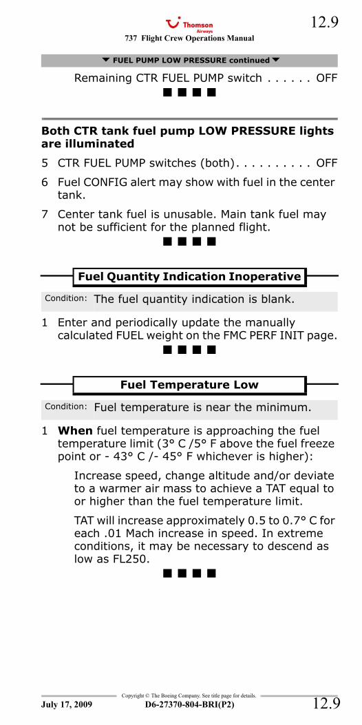
737 Flight Crew Operations Manual 12.9
Copyright © The Boeing Company. See title page for details.
D6-27370-804-BRI(P2) 12.9
Remaining CTR FUEL PUMP switch . . . . . . OFF
Both CTR tank fuel pump LOW PRESSURE lights are illuminated
5 CTR FUEL PUMP switches (both). . . . . . . . . . OFF
6 Fuel CONFIG alert may show with fuel in the center tank.
7 Center tank fuel is unusable. Main tank fuel may not be sufficient for the planned flight.
1 Enter and periodically update the manually calculated FUEL weight on the FMC PERF INIT page.
1 When fuel temperature is approaching the fuel temperature limit (3° C /5° F above the fuel freeze point or - 43° C /- 45° F whichever is higher):
Increase speed, change altitude and/or deviate to a warmer air mass to achieve a TAT equal to or higher than the fuel temperature limit.
TAT will increase approximately 0.5 to 0.7° C for each .01 Mach increase in speed. In extreme conditions, it may be necessary to descend as low as FL250.
FUEL PUMP LOW PRESSURE continued
Fuel Quantity Indication Inoperative
Condition: The fuel quantity indication is blank.
Fuel Temperature Low
Condition: Fuel temperature is near the minimum.
July 17, 2009
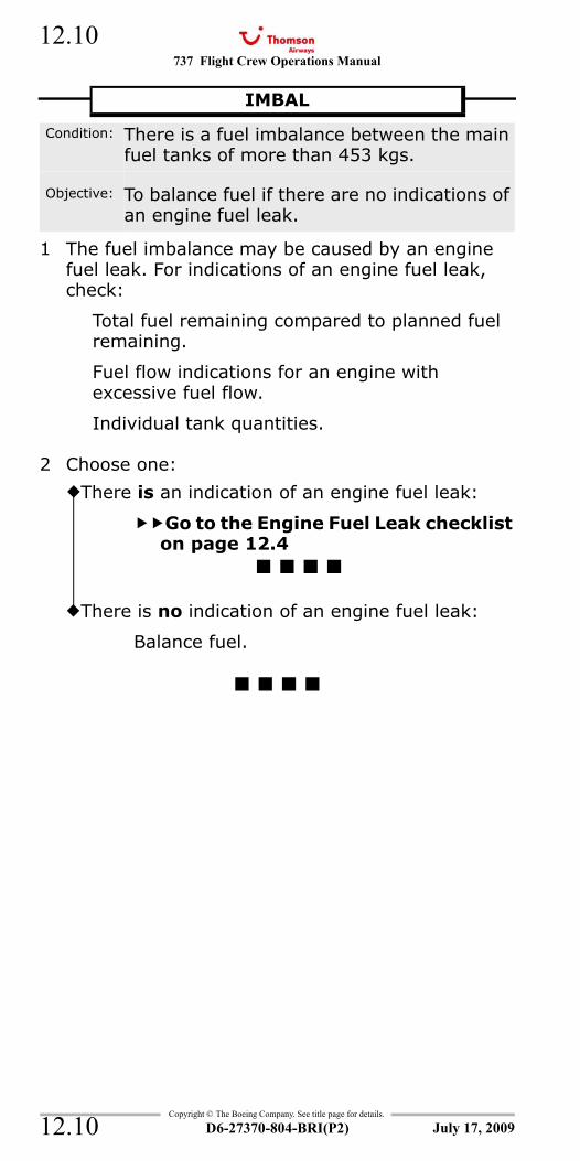
737 Flight Crew Operations Manual
Copyright © The Boeing Company. See title page for details.
D6-27370-804-BRI(P2)
12.10
12.10
IMBAL
1 The fuel imbalance may be caused by an engine fuel leak. For indications of an engine fuel leak, check:
Total fuel remaining compared to planned fuel remaining.
Fuel flow indications for an engine with excessive fuel flow.
Individual tank quantities.
2 Choose one:
IMBAL
Condition: There is a fuel imbalance between the main fuel tanks of more than 453 kgs.
Objective: To balance fuel if there are no indications of an engine fuel leak.
There is an indication of an engine fuel leak:
Go to the Engine Fuel Leak checklist on page 12.4
There is no indication of an engine fuel leak:
Balance fuel.
July 17, 2009
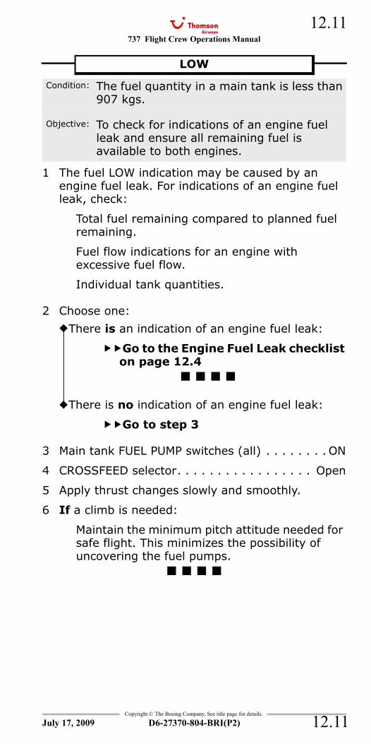
737 Flight Crew Operations Manual 12.11
Copyright © The Boeing Company. See title page for details.
D6-27370-804-BRI(P2) 12.11
LOW
1 The fuel LOW indication may be caused by an engine fuel leak. For indications of an engine fuel leak, check:
Total fuel remaining compared to planned fuel remaining.
Fuel flow indications for an engine with excessive fuel flow.
Individual tank quantities.
2 Choose one:
3 Main tank FUEL PUMP switches (all) . . . . . . . . ON
4 CROSSFEED selector. . . . . . . . . . . . . . . . . Open
5 Apply thrust changes slowly and smoothly.
6 If a climb is needed:
Maintain the minimum pitch attitude needed for safe flight. This minimizes the possibility of uncovering the fuel pumps.
LOW
Condition: The fuel quantity in a main tank is less than 907 kgs.
Objective: To check for indications of an engine fuel leak and ensure all remaining fuel is available to both engines.
There is an indication of an engine fuel leak:
Go to the Engine Fuel Leak checklist on page 12.4
There is no indication of an engine fuel leak:
Go to step 3
July 17, 2009

737 Flight Crew Operations Manual
Copyright © The Boeing Company. See title page for details.
D6-27370-804-BRI(P2)
12.12
12.12
IntentionallyBlank
July 17, 2009
737 Flight Crew Operations Manual
Non-Normal Checklists Chapter NNCHydraulics Section 13
Table of Contents
Copyright © The Boeing Company. See title page for details.
D6-27370-804-BRI(P2) 13.TOC.1
HYDRAULIC PUMP LOW PRESSURE ...................13.1HYDRAULIC PUMP OVERHEAT ..........................13.1LOSS OF SYSTEM A <>...................................13.2LOSS OF SYSTEM B <>...................................13.4MANUAL REVERSION or LOSS OF SYSTEM A AND
SYSTEM B <> ............................................13.8STANDBY HYDRAULIC LOW PRESSURE............ 13.13STANDBY HYDRAULIC LOW QUANTITY ............ 13.13
July 17, 2009
NNC.13-HydraulicsTable Of Contents

737 Flight Crew Operations Manual
Non-Normal Checklists -Hydraulics
Table of Contents
Copyright © The Boeing Company. See title page for details.
D6-27370-804-BRI(P2)13.TOC.2
IntentionallyBlank
July 17, 2009
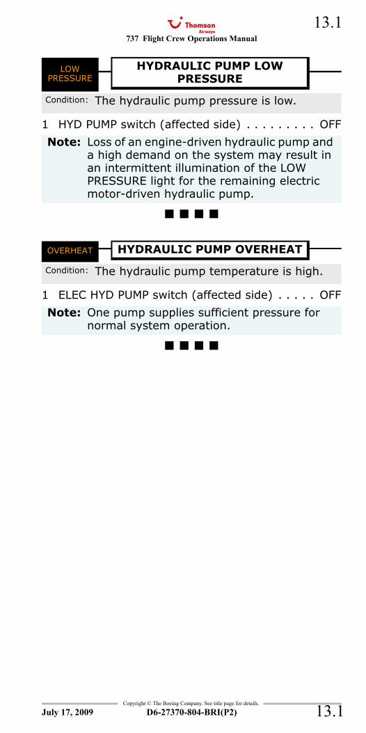
737 Flight Crew Operations Manual 13.1
Copyright © The Boeing Company. See title page for details.
D6-27370-804-BRI(P2) 13.1
NNC.13 Non-Normal Checklists-HydraulicsLOW PRESSURE - Hydraulic Pump (single)
1 HYD PUMP switch (affected side) . . . . . . . . . OFF
OVERHEAT - Hydraulic Pump
1 ELEC HYD PUMP switch (affected side) . . . . . OFF
LOW PRESSURE
HYDRAULIC PUMP LOWPRESSURE
Condition: The hydraulic pump pressure is low.
Note: Loss of an engine-driven hydraulic pump and a high demand on the system may result in an intermittent illumination of the LOW PRESSURE light for the remaining electric motor-driven hydraulic pump.
OVERHEAT HYDRAULIC PUMP OVERHEAT
Condition: The hydraulic pump temperature is high.
Note: One pump supplies sufficient pressure for normal system operation.
July 17, 2009
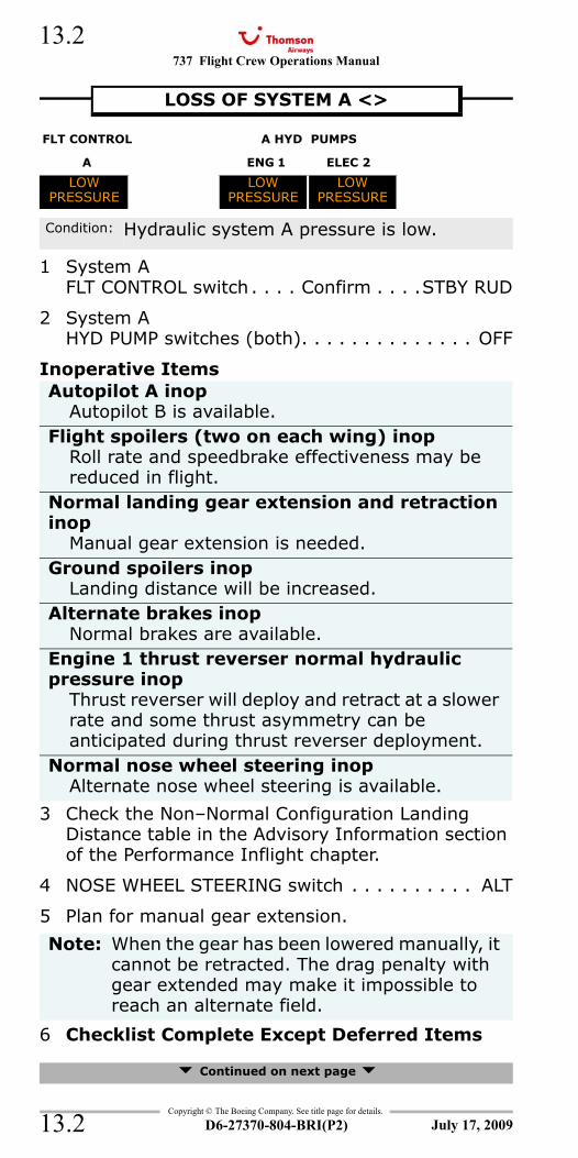
737 Flight Crew Operations Manual
Copyright © The Boeing Company. See title page for details.
D6-27370-804-BRI(P2)
13.2
13.2
LOW PRESSURE - Hydraulic Pump - System A (both)
1 System A FLT CONTROL switch . . . . Confirm . . . .STBY RUD
2 System A HYD PUMP switches (both). . . . . . . . . . . . . . OFF
Inoperative Items
3 Check the Non–Normal Configuration Landing Distance table in the Advisory Information section of the Performance Inflight chapter.
4 NOSE WHEEL STEERING switch . . . . . . . . . . ALT
5 Plan for manual gear extension.
6 Checklist Complete Except Deferred Items
Continued on next page
LOSS OF SYSTEM A <>
FLT CONTROL A HYD PUMPS
A ENG 1 ELEC 2
LOW PRESSURE
LOWPRESSURE
LOWPRESSURE
Condition: Hydraulic system A pressure is low.
Autopilot A inopAutopilot B is available.
Flight spoilers (two on each wing) inopRoll rate and speedbrake effectiveness may be reduced in flight.
Normal landing gear extension and retraction inop
Manual gear extension is needed.Ground spoilers inop
Landing distance will be increased.Alternate brakes inop
Normal brakes are available.Engine 1 thrust reverser normal hydraulic pressure inop
Thrust reverser will deploy and retract at a slower rate and some thrust asymmetry can be anticipated during thrust reverser deployment.
Normal nose wheel steering inopAlternate nose wheel steering is available.
Note: When the gear has been lowered manually, it cannot be retracted. The drag penalty with gear extended may make it impossible to reach an alternate field.
July 17, 2009
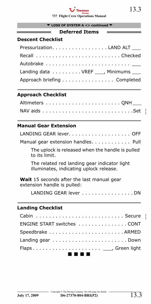
737 Flight Crew Operations Manual 13.3
Copyright © The Boeing Company. See title page for details.
D6-27370-804-BRI(P2) 13.3
Descent Checklist
Pressurization. . . . . . . . . . . . . . . . . LAND ALT ___
Recall . . . . . . . . . . . . . . . . . . . . . . . . . . Checked
Autobrake . . . . . . . . . . . . . . . . . . . . . . . . . . ___
Landing data . . . . . . . . . VREF ___, Minimums ___
Approach briefing . . . . . . . . . . . . . . . . Completed
Approach Checklist
Altimeters . . . . . . . . . . . . . . . . . . . . . . . QNH ___
NAV aids . . . . . . . . . . . . . . . . . . . . . . . . . . . .Set
Manual Gear Extension
LANDING GEAR lever. . . . . . . . . . . . . . . . . . . OFF
Manual gear extension handles. . . . . . . . . . . . Pull
The uplock is released when the handle is pulled to its limit.
The related red landing gear indicator light illuminates, indicating uplock release.
Wait 15 seconds after the last manual gear extension handle is pulled:
LANDING GEAR lever . . . . . . . . . . . . . . . . DN
Landing Checklist
Cabin . . . . . . . . . . . . . . . . . . . . . . . . . . . Secure
ENGINE START switches . . . . . . . . . . . . . . . CONT
Speedbrake . . . . . . . . . . . . . . . . . . . . . . . ARMED
Landing gear . . . . . . . . . . . . . . . . . . . . . . . Down
Flaps . . . . . . . . . . . . . . . . . . . . . ___, Green light
LOSS OF SYSTEM A <> continued
Deferred Items
July 17, 2009
::::
::::
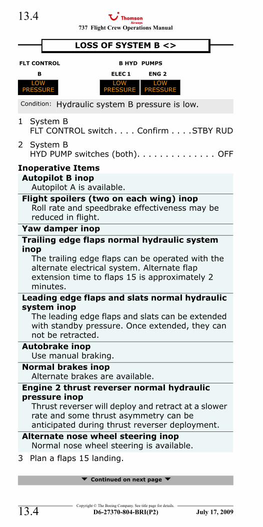
737 Flight Crew Operations Manual
Copyright © The Boeing Company. See title page for details.
D6-27370-804-BRI(P2)
13.4
13.4
LOW PRESSURE - Hydraulic Pump - System B (both)
1 System BFLT CONTROL switch . . . . Confirm . . . .STBY RUD
2 System B HYD PUMP switches (both). . . . . . . . . . . . . . OFF
Inoperative Items
3 Plan a flaps 15 landing.
Continued on next page
LOSS OF SYSTEM B <>
FLT CONTROL B HYD PUMPS
B ELEC 1 ENG 2
LOW PRESSURE
LOWPRESSURE
LOWPRESSURE
Condition: Hydraulic system B pressure is low.
Autopilot B inopAutopilot A is available.
Flight spoilers (two on each wing) inopRoll rate and speedbrake effectiveness may be reduced in flight.
Yaw damper inopTrailing edge flaps normal hydraulic system inop
The trailing edge flaps can be operated with the alternate electrical system. Alternate flap extension time to flaps 15 is approximately 2 minutes.
Leading edge flaps and slats normal hydraulic system inop
The leading edge flaps and slats can be extended with standby pressure. Once extended, they can not be retracted.
Autobrake inopUse manual braking.
Normal brakes inopAlternate brakes are available.
Engine 2 thrust reverser normal hydraulic pressure inop
Thrust reverser will deploy and retract at a slower rate and some thrust asymmetry can be anticipated during thrust reverser deployment.
Alternate nose wheel steering inopNormal nose wheel steering is available.
July 17, 2009
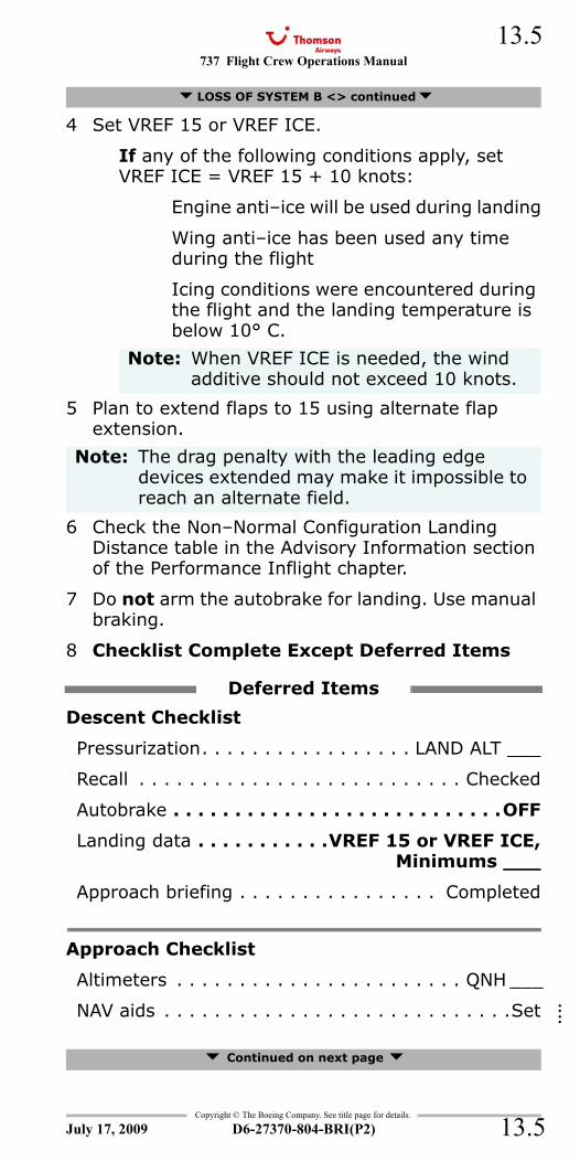
737 Flight Crew Operations Manual 13.5
Copyright © The Boeing Company. See title page for details.
D6-27370-804-BRI(P2) 13.5
4 Set VREF 15 or VREF ICE.
If any of the following conditions apply, set VREF ICE = VREF 15 + 10 knots:
Engine anti–ice will be used during landing
Wing anti–ice has been used any time during the flight
Icing conditions were encountered during the flight and the landing temperature is below 10° C.
5 Plan to extend flaps to 15 using alternate flap extension.
6 Check the Non–Normal Configuration Landing Distance table in the Advisory Information section of the Performance Inflight chapter.
7 Do not arm the autobrake for landing. Use manual braking.
8 Checklist Complete Except Deferred Items
Descent Checklist
Pressurization. . . . . . . . . . . . . . . . . LAND ALT ___
Recall . . . . . . . . . . . . . . . . . . . . . . . . . . Checked
Autobrake . . . . . . . . . . . . . . . . . . . . . . . . . . .OFF
Landing data . . . . . . . . . . .VREF 15 or VREF ICE,Minimums ___
Approach briefing . . . . . . . . . . . . . . . . Completed
Approach Checklist
Altimeters . . . . . . . . . . . . . . . . . . . . . . . QNH ___
NAV aids . . . . . . . . . . . . . . . . . . . . . . . . . . . .Set
Continued on next page
LOSS OF SYSTEM B <> continued
Note: When VREF ICE is needed, the wind additive should not exceed 10 knots.
Note: The drag penalty with the leading edge devices extended may make it impossible to reach an alternate field.
Deferred Items
July 17, 2009
::::
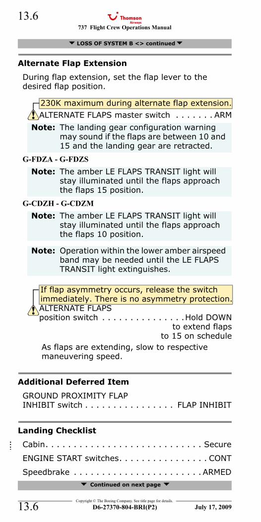
737 Flight Crew Operations Manual
Copyright © The Boeing Company. See title page for details.
D6-27370-804-BRI(P2)
13.6
13.6
Alternate Flap Extension
During flap extension, set the flap lever to the desired flap position.
G-FDZA - G-FDZS
G-CDZH - G-CDZM
As flaps are extending, slow to respective maneuvering speed.
Additional Deferred Item
GROUND PROXIMITY FLAPINHIBIT switch . . . . . . . . . . . . . . . . FLAP INHIBIT
Landing Checklist
Cabin. . . . . . . . . . . . . . . . . . . . . . . . . . . . Secure
ENGINE START switches. . . . . . . . . . . . . . . . CONT
Speedbrake . . . . . . . . . . . . . . . . . . . . . . . ARMED Continued on next page
LOSS OF SYSTEM B <> continued
230K maximum during alternate flap extension.
ALTERNATE FLAPS master switch . . . . . . . ARM
Note: The landing gear configuration warning may sound if the flaps are between 10 and 15 and the landing gear are retracted.
Note: The amber LE FLAPS TRANSIT light will stay illuminated until the flaps approach the flaps 15 position.
Note: The amber LE FLAPS TRANSIT light will stay illuminated until the flaps approach the flaps 10 position.
Note: Operation within the lower amber airspeed band may be needed until the LE FLAPS TRANSIT light extinguishes.
If flap asymmetry occurs, release the switch immediately. There is no asymmetry protection.ALTERNATE FLAPS position switch . . . . . . . . . . . . . . .Hold DOWN
to extend flapsto 15 on schedule
July 17, 2009
::::
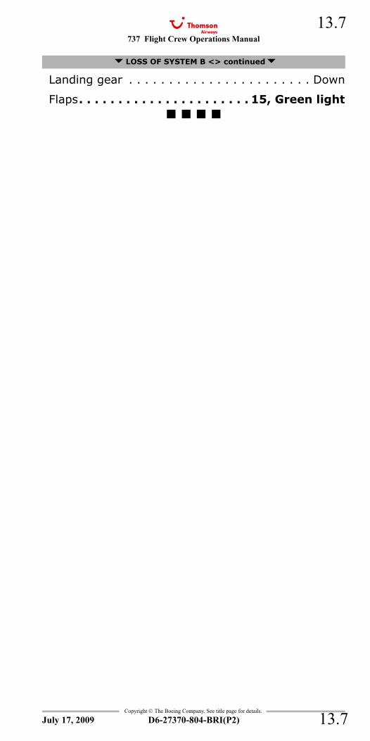
737 Flight Crew Operations Manual 13.7
Copyright © The Boeing Company. See title page for details.
D6-27370-804-BRI(P2) 13.7
Landing gear . . . . . . . . . . . . . . . . . . . . . . . Down
Flaps. . . . . . . . . . . . . . . . . . . . . . 15, Green light
LOSS OF SYSTEM B <> continued
July 17, 2009
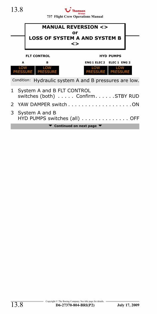
737 Flight Crew Operations Manual
Copyright © The Boeing Company. See title page for details.
D6-27370-804-BRI(P2)
13.8
13.8
LOW PRESSURE - Hydraulic Pump - System A and B
1 System A and B FLT CONTROL switches (both) . . . . . Confirm. . . . . .STBY RUD
2 YAW DAMPER switch . . . . . . . . . . . . . . . . . . .ON
3 System A and BHYD PUMPS switches (all) . . . . . . . . . . . . . . OFF
Continued on next page
MANUAL REVERSION <>or
LOSS OF SYSTEM A AND SYSTEM B <>
MANUAL REVERSION or LOSS OF SYSTEM A AND SYSTEM B <>
FLT CONTROL HYD PUMPS
A B ENG 1 ELEC 2 ELEC 1 ENG 2
LOWPRESSURE
LOWPRESSURE
LOWPRESSURE
LOWPRESSURE
Condition: Hydraulic system A and B pressures are low.
July 17, 2009
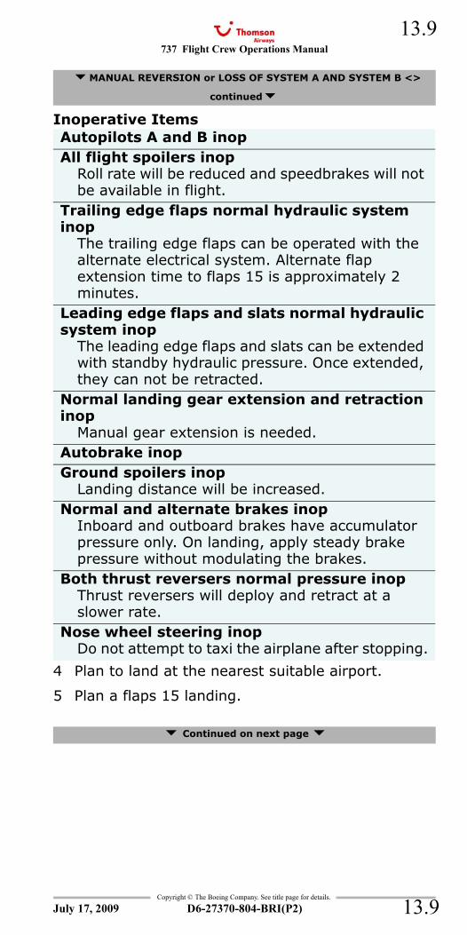
737 Flight Crew Operations Manual 13.9
Copyright © The Boeing Company. See title page for details.
D6-27370-804-BRI(P2) 13.9
Inoperative Items
4 Plan to land at the nearest suitable airport.
5 Plan a flaps 15 landing.
Continued on next page
MANUAL REVERSION or LOSS OF SYSTEM A AND SYSTEM B <>
continued
Autopilots A and B inopAll flight spoilers inop
Roll rate will be reduced and speedbrakes will not be available in flight.
Trailing edge flaps normal hydraulic system inop
The trailing edge flaps can be operated with the alternate electrical system. Alternate flap extension time to flaps 15 is approximately 2 minutes.
Leading edge flaps and slats normal hydraulic system inop
The leading edge flaps and slats can be extended with standby hydraulic pressure. Once extended, they can not be retracted.
Normal landing gear extension and retraction inop
Manual gear extension is needed.Autobrake inopGround spoilers inop
Landing distance will be increased.Normal and alternate brakes inop
Inboard and outboard brakes have accumulator pressure only. On landing, apply steady brake pressure without modulating the brakes.
Both thrust reversers normal pressure inopThrust reversers will deploy and retract at a slower rate.
Nose wheel steering inopDo not attempt to taxi the airplane after stopping.
July 17, 2009
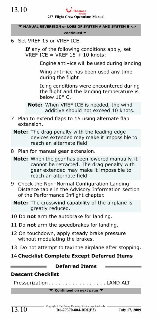
737 Flight Crew Operations Manual
Copyright © The Boeing Company. See title page for details.
D6-27370-804-BRI(P2)
13.10
13.10
6 Set VREF 15 or VREF ICE.
If any of the following conditions apply, set VREF ICE = VREF 15 + 10 knots:
Engine anti–ice will be used during landing
Wing anti–ice has been used any time during the flight
Icing conditions were encountered during the flight and the landing temperature is below 10° C.
7 Plan to extend flaps to 15 using alternate flap extension.
8 Plan for manual gear extension.
9 Check the Non–Normal Configuration Landing Distance table in the Advisory Information section of the Performance Inflight chapter.
10 Do not arm the autobrake for landing.
11 Do not arm the speedbrakes for landing.
12 On touchdown, apply steady brake pressure without modulating the brakes.
13 Do not attempt to taxi the airplane after stopping.
14 Checklist Complete Except Deferred Items
Descent Checklist
Pressurization. . . . . . . . . . . . . . . . . LAND ALT ___ Continued on next page
MANUAL REVERSION or LOSS OF SYSTEM A AND SYSTEM B <>
continued
Note: When VREF ICE is needed, the wind additive should not exceed 10 knots.
Note: The drag penalty with the leading edge devices extended may make it impossible to reach an alternate field.
Note: When the gear has been lowered manually, it cannot be retracted. The drag penalty with gear extended may make it impossible to reach an alternate field.
Note: The crosswind capability of the airplane is greatly reduced.
Deferred Items
July 17, 2009
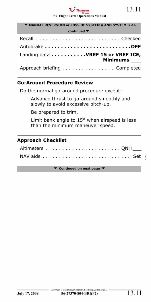
737 Flight Crew Operations Manual 13.11
Copyright © The Boeing Company. See title page for details.
D6-27370-804-BRI(P2) 13.11
Recall . . . . . . . . . . . . . . . . . . . . . . . . . . Checked
Autobrake . . . . . . . . . . . . . . . . . . . . . . . . . . .OFF
Landing data . . . . . . . . . . .VREF 15 or VREF ICE,Minimums ___
Approach briefing . . . . . . . . . . . . . . . . Completed
Go-Around Procedure Review
Do the normal go-around procedure except:
Advance thrust to go-around smoothly and slowly to avoid excessive pitch-up.
Be prepared to trim.
Limit bank angle to 15° when airspeed is less than the minimum maneuver speed.
Approach Checklist
Altimeters . . . . . . . . . . . . . . . . . . . . . . . QNH ___
NAV aids . . . . . . . . . . . . . . . . . . . . . . . . . . . .Set
Continued on next page
MANUAL REVERSION or LOSS OF SYSTEM A AND SYSTEM B <>
continued
July 17, 2009
::::
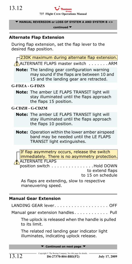
737 Flight Crew Operations Manual
Copyright © The Boeing Company. See title page for details.
D6-27370-804-BRI(P2)
13.12
13.12
Alternate Flap Extension
During flap extension, set the flap lever to the desired flap position.
G-FDZA - G-FDZS
G-CDZH - G-CDZM
As flaps are extending, slow to respective maneuvering speed.
Manual Gear Extension
LANDING GEAR lever. . . . . . . . . . . . . . . . . . . OFF
Manual gear extension handles . . . . . . . . . . . . Pull
The uplock is released when the handle is pulled to its limit.
The related red landing gear indicator light illuminates, indicating uplock release.
Continued on next page
MANUAL REVERSION or LOSS OF SYSTEM A AND SYSTEM B <>
continued
230K maximum during alternate flap extension.
ALTERNATE FLAPS master switch . . . . . . . ARM
Note: The landing gear configuration warning may sound if the flaps are between 10 and 15 and the landing gear are retracted.
Note: The amber LE FLAPS TRANSIT light will stay illuminated until the flaps approach the flaps 15 position.
Note: The amber LE FLAPS TRANSIT light will stay illuminated until the flaps approach the flaps 10 position.
Note: Operation within the lower amber airspeed band may be needed until the LE FLAPS TRANSIT light extinguishes.
If flap asymmetry occurs, release the switch immediately. There is no asymmetry protection.ALTERNATE FLAPS position switch . . . . . . . . . . . . . . .Hold DOWN
to extend flapsto 15 on schedule
July 17, 2009
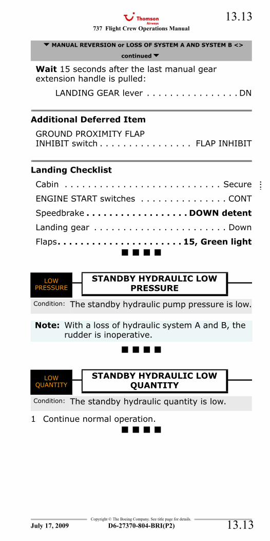
737 Flight Crew Operations Manual 13.13
Copyright © The Boeing Company. See title page for details.
D6-27370-804-BRI(P2) 13.13
Wait 15 seconds after the last manual gear extension handle is pulled:
LANDING GEAR lever . . . . . . . . . . . . . . . . DN
Additional Deferred Item
GROUND PROXIMITY FLAPINHIBIT switch . . . . . . . . . . . . . . . . FLAP INHIBIT
Landing Checklist
Cabin . . . . . . . . . . . . . . . . . . . . . . . . . . . Secure
ENGINE START switches . . . . . . . . . . . . . . . CONT
Speedbrake . . . . . . . . . . . . . . . . . . DOWN detent
Landing gear . . . . . . . . . . . . . . . . . . . . . . . Down
Flaps. . . . . . . . . . . . . . . . . . . . . . 15, Green light
LOW PRESSURE - Hydraulic Pump - Standby
LOW QUANTITY
1 Continue normal operation.
MANUAL REVERSION or LOSS OF SYSTEM A AND SYSTEM B <>
continued
LOW PRESSURE
STANDBY HYDRAULIC LOWPRESSURE
Condition: The standby hydraulic pump pressure is low.
Note: With a loss of hydraulic system A and B, the rudder is inoperative.
LOW QUANTITY
STANDBY HYDRAULIC LOWQUANTITY
Condition: The standby hydraulic quantity is low.
July 17, 2009
::::
737 Flight Crew Operations Manual
Copyright © The Boeing Company. See title page for details.
D6-27370-804-BRI(P2)
13.14
13.14
IntentionallyBlank
July 17, 2009
737 Flight Crew Operations Manual
Non-Normal Checklists Chapter NNCLanding Gear Section 14
Table of Contents
Copyright © The Boeing Company. See title page for details.
D6-27370-804-BRI(P2) 14.TOC.1
ANTISKID INOPERATIVE <>............................14.1AUTO BRAKE DISARM <> ...............................14.4Brake Pressure Indicator Zero PSI ....................14.5Landing Gear Lever Jammed in the Up
Position <>................................................14.6Landing Gear Lever Will Not Move Up After
Takeoff <> ................................................14.9Manual Gear Extension ................................. 14.12Partial or All Gear Up Landing <>................... 14.14WHEEL WELL FIRE.................................... 8.18
July 17, 2009
NNC.14-Landing GearTable Of Contents

737 Flight Crew Operations Manual
Non-Normal Checklists -Landing Gear
Table of Contents
Copyright © The Boeing Company. See title page for details.
D6-27370-804-BRI(P2)14.TOC.2
IntentionallyBlank
July 17, 2009
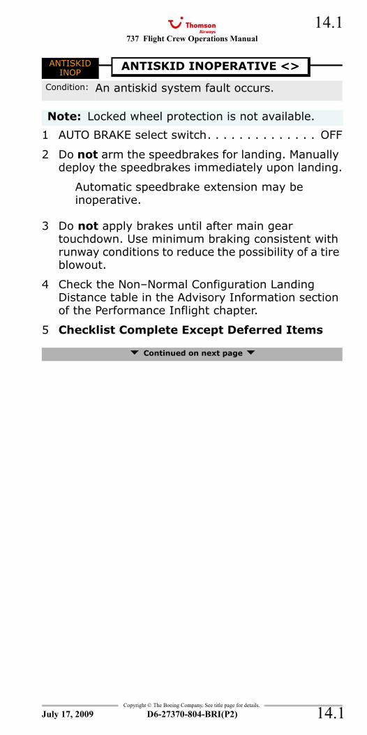
737 Flight Crew Operations Manual 14.1
Copyright © The Boeing Company. See title page for details.
D6-27370-804-BRI(P2) 14.1
NNC.14 Non-Normal Checklists-Landing GearANTISKID INOP
1 AUTO BRAKE select switch. . . . . . . . . . . . . . OFF
2 Do not arm the speedbrakes for landing. Manually deploy the speedbrakes immediately upon landing.
Automatic speedbrake extension may be inoperative.
3 Do not apply brakes until after main gear touchdown. Use minimum braking consistent with runway conditions to reduce the possibility of a tire blowout.
4 Check the Non–Normal Configuration Landing Distance table in the Advisory Information section of the Performance Inflight chapter.
5 Checklist Complete Except Deferred Items
Continued on next page
ANTISKID INOP
ANTISKID INOPERATIVE <>
Condition: An antiskid system fault occurs.
Note: Locked wheel protection is not available.
July 17, 2009
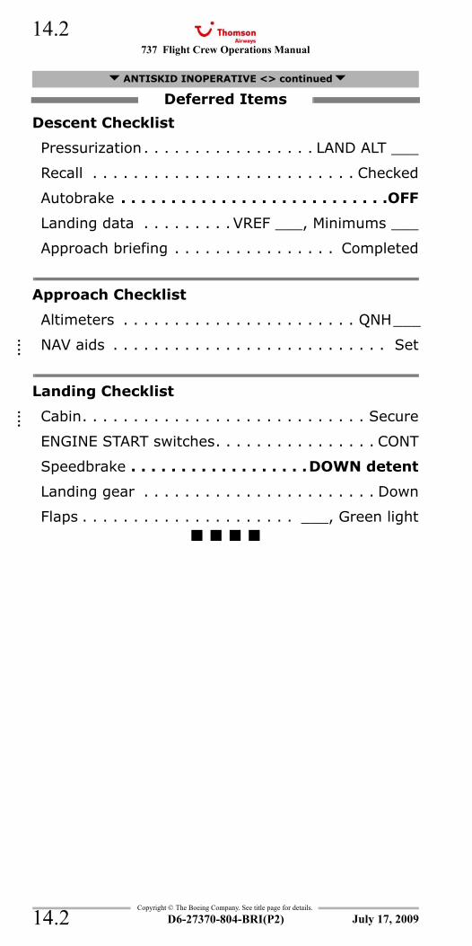
737 Flight Crew Operations Manual
Copyright © The Boeing Company. See title page for details.
D6-27370-804-BRI(P2)
14.2
14.2
Descent Checklist
Pressurization. . . . . . . . . . . . . . . . . LAND ALT ___
Recall . . . . . . . . . . . . . . . . . . . . . . . . . . Checked
Autobrake . . . . . . . . . . . . . . . . . . . . . . . . . . .OFF
Landing data . . . . . . . . . VREF ___, Minimums ___
Approach briefing . . . . . . . . . . . . . . . . Completed
Approach Checklist
Altimeters . . . . . . . . . . . . . . . . . . . . . . . QNH___
NAV aids . . . . . . . . . . . . . . . . . . . . . . . . . . . Set
Landing Checklist
Cabin. . . . . . . . . . . . . . . . . . . . . . . . . . . . Secure
ENGINE START switches. . . . . . . . . . . . . . . . CONT
Speedbrake . . . . . . . . . . . . . . . . . .DOWN detent
Landing gear . . . . . . . . . . . . . . . . . . . . . . . Down
Flaps . . . . . . . . . . . . . . . . . . . . . ___, Green light
ANTISKID INOPERATIVE <> continued
Deferred Items
July 17, 2009
::::
::::

737 Flight Crew Operations Manual 14.3
Copyright © The Boeing Company. See title page for details.
D6-27370-804-BRI(P2) 14.3
IntentionallyBlank
July 17, 2009
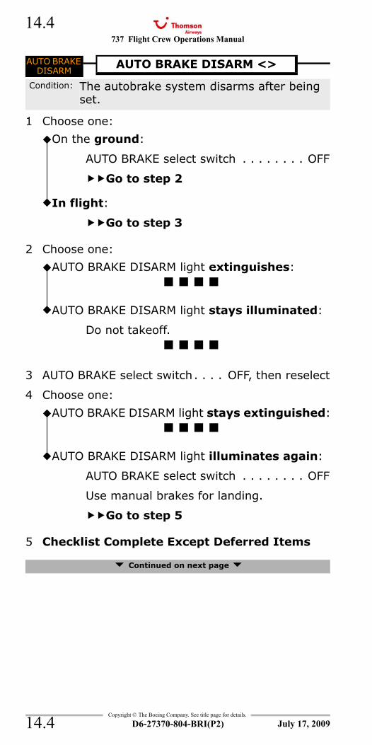
737 Flight Crew Operations Manual
Copyright © The Boeing Company. See title page for details.
D6-27370-804-BRI(P2)
14.4
14.4
AUTO BRAKE DISARM
1 Choose one:
2 Choose one:
3 AUTO BRAKE select switch. . . . OFF, then reselect
4 Choose one:
5 Checklist Complete Except Deferred Items
Continued on next page
AUTO BRAKE DISARM
AUTO BRAKE DISARM <>
Condition: The autobrake system disarms after being set.
On the ground:
AUTO BRAKE select switch . . . . . . . . OFF
Go to step 2
In flight:
Go to step 3
AUTO BRAKE DISARM light extinguishes:
AUTO BRAKE DISARM light stays illuminated:
Do not takeoff.
AUTO BRAKE DISARM light stays extinguished:
AUTO BRAKE DISARM light illuminates again:
AUTO BRAKE select switch . . . . . . . . OFF
Use manual brakes for landing.
Go to step 5
July 17, 2009
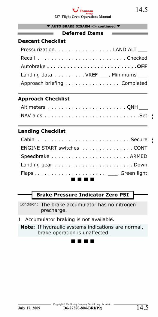
737 Flight Crew Operations Manual 14.5
Copyright © The Boeing Company. See title page for details.
D6-27370-804-BRI(P2) 14.5
Descent Checklist
Pressurization. . . . . . . . . . . . . . . . . LAND ALT ___
Recall . . . . . . . . . . . . . . . . . . . . . . . . . . Checked
Autobrake . . . . . . . . . . . . . . . . . . . . . . . . . . .OFF
Landing data . . . . . . . . . VREF ___, Minimums ___
Approach briefing . . . . . . . . . . . . . . . . Completed
Approach Checklist
Altimeters . . . . . . . . . . . . . . . . . . . . . . . QNH ___
NAV aids . . . . . . . . . . . . . . . . . . . . . . . . . . . .Set
Landing Checklist
Cabin . . . . . . . . . . . . . . . . . . . . . . . . . . . Secure
ENGINE START switches . . . . . . . . . . . . . . . CONT
Speedbrake . . . . . . . . . . . . . . . . . . . . . . . ARMED
Landing gear . . . . . . . . . . . . . . . . . . . . . . . Down
Flaps . . . . . . . . . . . . . . . . . . . . . ___, Green light
1 Accumulator braking is not available.
AUTO BRAKE DISARM <> continued
Deferred Items
Brake Pressure Indicator Zero PSI
Condition: The brake accumulator has no nitrogen precharge.
Note: If hydraulic systems indications are normal, brake operation is unaffected.
July 17, 2009
::::
::::
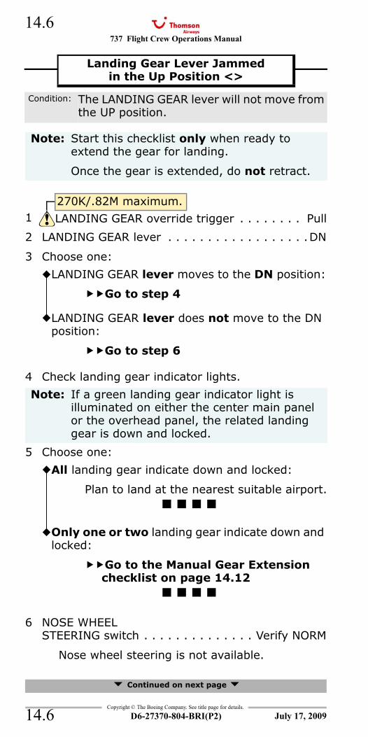
737 Flight Crew Operations Manual
Copyright © The Boeing Company. See title page for details.
D6-27370-804-BRI(P2)
14.6
14.6
2 LANDING GEAR lever . . . . . . . . . . . . . . . . . .DN
3 Choose one:
4 Check landing gear indicator lights.
5 Choose one:
6 NOSE WHEELSTEERING switch . . . . . . . . . . . . . . Verify NORM
Nose wheel steering is not available.
Continued on next page
Landing Gear Lever Jammedin the Up Position <>
Condition: The LANDING GEAR lever will not move from the UP position.
Note: Start this checklist only when ready to extend the gear for landing.
Once the gear is extended, do not retract.
270K/.82M maximum.1 LANDING GEAR override trigger . . . . . . . . Pull
LANDING GEAR lever moves to the DN position:
Go to step 4
LANDING GEAR lever does not move to the DN position:
Go to step 6
Note: If a green landing gear indicator light is illuminated on either the center main panel or the overhead panel, the related landing gear is down and locked.
All landing gear indicate down and locked:
Plan to land at the nearest suitable airport.
Only one or two landing gear indicate down and locked:
Go to the Manual Gear Extension checklist on page 14.12
July 17, 2009
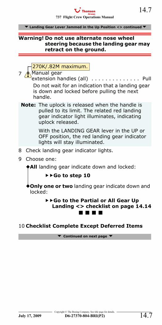
737 Flight Crew Operations Manual 14.7
Copyright © The Boeing Company. See title page for details.
D6-27370-804-BRI(P2) 14.7
Warning! Do not use alternate nose wheel steering because the landing gear may retract on the ground.
Do not wait for an indication that a landing gear is down and locked before pulling the next handle.
8 Check landing gear indicator lights.
9 Choose one:
10 Checklist Complete Except Deferred Items
Continued on next page
Landing Gear Lever Jammed in the Up Position <> continued
270K/.82M maximum.7 Manual gear
extension handles (all) . . . . . . . . . . . . . . Pull
Note: The uplock is released when the handle is pulled to its limit. The related red landing gear indicator light illuminates, indicating uplock released.
With the LANDING GEAR lever in the UP or OFF position, the red landing gear indicator lights will stay illuminated.
All landing gear indicate down and locked:
Go to step 10
Only one or two landing gear indicate down and locked:
Go to the Partial or All Gear Up Landing <> checklist on page 14.14
July 17, 2009
737 Flight Crew Operations Manual
Copyright © The Boeing Company. See title page for details.
D6-27370-804-BRI(P2)
14.8
14.8
Descent Checklist
Pressurization. . . . . . . . . . . . . . . . . LAND ALT ___
Recall . . . . . . . . . . . . . . . . . . . . . . . . . . Checked
Autobrake . . . . . . . . . . . . . . . . . . . . . . . . . . ___
Landing data . . . . . . . . . VREF ___, Minimums ___
Approach briefing . . . . . . . . . . . . . . . . Completed
Approach Checklist
Altimeters . . . . . . . . . . . . . . . . . . . . . . . QNH___
NAV aids . . . . . . . . . . . . . . . . . . . . . . . . . . . Set
Additional Deferred Item
GROUND PROXIMITY GEARINHIBIT switch . . . . . . . . . . . . . . . . GEAR INHIBIT
Landing Checklist
Cabin. . . . . . . . . . . . . . . . . . . . . . . . . . . . Secure
ENGINE START switches. . . . . . . . . . . . . . . . CONT
Speedbrake . . . . . . . . . . . . . . . . . . . . . . . ARMED
Landing gear . . . . . . . . . . . . Down, Three green
Flaps . . . . . . . . . . . . . . . . . . . . . ___, Green light
Warning! Do not use alternate nose wheel steering because the landing gear may retract on the ground.
Landing Gear Lever Jammed in the Up Position <> continued
Deferred Items
Note: Nose wheel steering is not available.
July 17, 2009
::::
::::
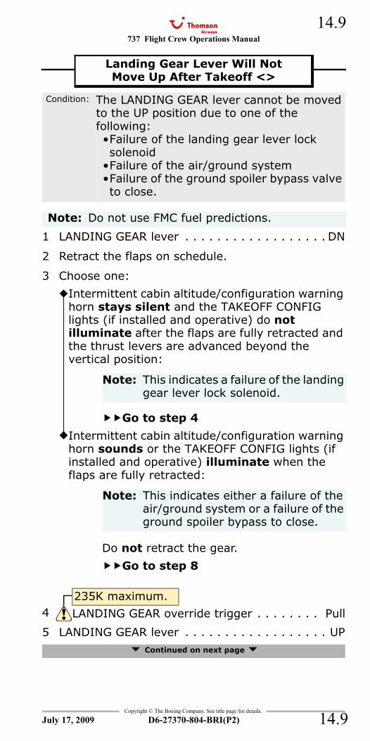
737 Flight Crew Operations Manual 14.9
Copyright © The Boeing Company. See title page for details.
D6-27370-804-BRI(P2) 14.9
1 LANDING GEAR lever . . . . . . . . . . . . . . . . . . DN
2 Retract the flaps on schedule.
3 Choose one:
5 LANDING GEAR lever . . . . . . . . . . . . . . . . . . UP Continued on next page
Landing Gear Lever Will NotMove Up After Takeoff <>
Condition: The LANDING GEAR lever cannot be moved to the UP position due to one of the following:•Failure of the landing gear lever lock solenoid
•Failure of the air/ground system•Failure of the ground spoiler bypass valve to close.
Note: Do not use FMC fuel predictions.
Intermittent cabin altitude/configuration warning horn stays silent and the TAKEOFF CONFIG lights (if installed and operative) do not illuminate after the flaps are fully retracted and the thrust levers are advanced beyond the vertical position:
Note: This indicates a failure of the landing gear lever lock solenoid.
Go to step 4
Intermittent cabin altitude/configuration warning horn sounds or the TAKEOFF CONFIG lights (if installed and operative) illuminate when the flaps are fully retracted:
Note: This indicates either a failure of the air/ground system or a failure of the ground spoiler bypass to close.
Do not retract the gear.
Go to step 8
235K maximum.4 LANDING GEAR override trigger . . . . . . . . Pull
July 17, 2009
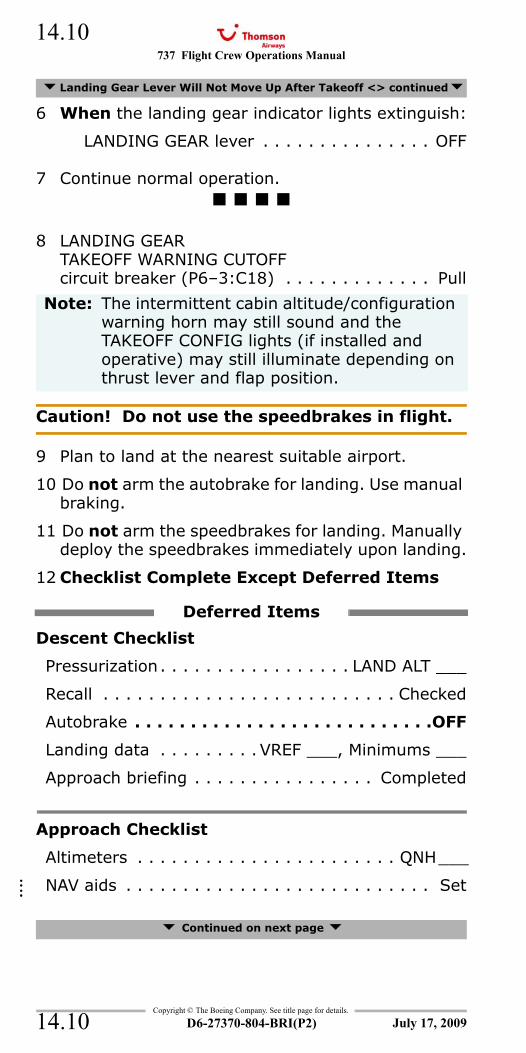
737 Flight Crew Operations Manual
Copyright © The Boeing Company. See title page for details.
D6-27370-804-BRI(P2)
14.10
14.10
6 When the landing gear indicator lights extinguish:
LANDING GEAR lever . . . . . . . . . . . . . . . OFF
7 Continue normal operation.
8 LANDING GEARTAKEOFF WARNING CUTOFF circuit breaker (P6–3:C18) . . . . . . . . . . . . . Pull
Caution! Do not use the speedbrakes in flight.
9 Plan to land at the nearest suitable airport.
10 Do not arm the autobrake for landing. Use manual braking.
11 Do not arm the speedbrakes for landing. Manually deploy the speedbrakes immediately upon landing.
12 Checklist Complete Except Deferred Items
Descent Checklist
Pressurization. . . . . . . . . . . . . . . . . LAND ALT ___
Recall . . . . . . . . . . . . . . . . . . . . . . . . . . Checked
Autobrake . . . . . . . . . . . . . . . . . . . . . . . . . . .OFF
Landing data . . . . . . . . . VREF ___, Minimums ___
Approach briefing . . . . . . . . . . . . . . . . Completed
Approach Checklist
Altimeters . . . . . . . . . . . . . . . . . . . . . . . QNH___
NAV aids . . . . . . . . . . . . . . . . . . . . . . . . . . . Set
Continued on next page
Landing Gear Lever Will Not Move Up After Takeoff <> continued
Note: The intermittent cabin altitude/configuration warning horn may still sound and the TAKEOFF CONFIG lights (if installed and operative) may still illuminate depending on thrust lever and flap position.
Deferred Items
July 17, 2009
::::
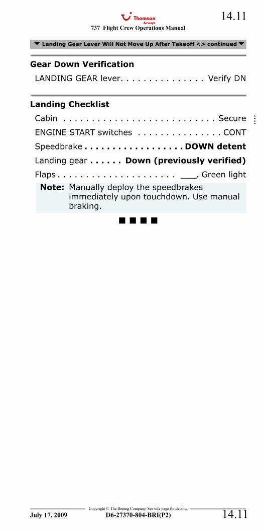
737 Flight Crew Operations Manual 14.11
Copyright © The Boeing Company. See title page for details.
D6-27370-804-BRI(P2) 14.11
Gear Down Verification
LANDING GEAR lever. . . . . . . . . . . . . . . Verify DN
Landing Checklist
Cabin . . . . . . . . . . . . . . . . . . . . . . . . . . . Secure
ENGINE START switches . . . . . . . . . . . . . . . CONT
Speedbrake . . . . . . . . . . . . . . . . . . DOWN detent
Landing gear . . . . . . Down (previously verified)
Flaps . . . . . . . . . . . . . . . . . . . . . ___, Green light
Landing Gear Lever Will Not Move Up After Takeoff <> continued
Note: Manually deploy the speedbrakes immediately upon touchdown. Use manual braking.
July 17, 2009
::::
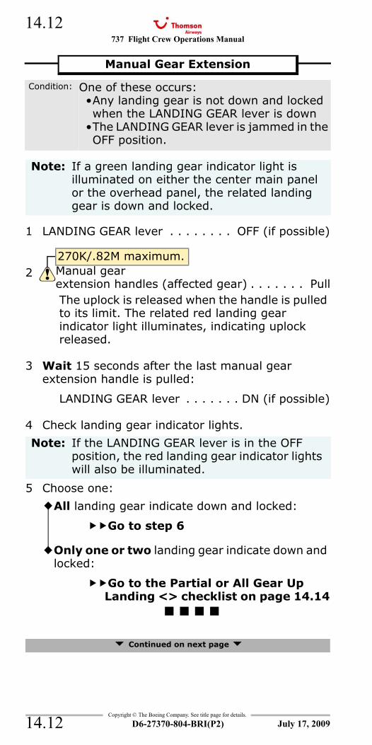
737 Flight Crew Operations Manual
Copyright © The Boeing Company. See title page for details.
D6-27370-804-BRI(P2)
14.12
14.12
1 LANDING GEAR lever . . . . . . . . OFF (if possible)
The uplock is released when the handle is pulled to its limit. The related red landing gear indicator light illuminates, indicating uplock released.
3 Wait 15 seconds after the last manual gear extension handle is pulled:
LANDING GEAR lever . . . . . . . DN (if possible)
4 Check landing gear indicator lights.
5 Choose one:
Continued on next page
Manual Gear Extension
Condition: One of these occurs:•Any landing gear is not down and locked when the LANDING GEAR lever is down
•The LANDING GEAR lever is jammed in the OFF position.
Note: If a green landing gear indicator light is illuminated on either the center main panel or the overhead panel, the related landing gear is down and locked.
270K/.82M maximum.2 Manual gear
extension handles (affected gear) . . . . . . . Pull
Note: If the LANDING GEAR lever is in the OFF position, the red landing gear indicator lights will also be illuminated.
All landing gear indicate down and locked:
Go to step 6
Only one or two landing gear indicate down and locked:
Go to the Partial or All Gear Up Landing <> checklist on page 14.14
July 17, 2009
737 Flight Crew Operations Manual 14.13
Copyright © The Boeing Company. See title page for details.
D6-27370-804-BRI(P2) 14.13
6 Choose one:
Manual Gear Extension continued
LANDING GEAR lever is in the DN position:
Land normally.
LANDING GEAR lever is in the OFF position:
GROUND PROXIMITY GEARINHIBIT switch . . . . . . .GEAR INHIBIT
Land normally.
Note: Nose wheel steering is not available.
July 17, 2009
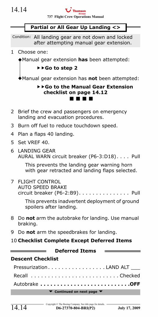
737 Flight Crew Operations Manual
Copyright © The Boeing Company. See title page for details.
D6-27370-804-BRI(P2)
14.14
14.14
1 Choose one:
2 Brief the crew and passengers on emergency landing and evacuation procedures.
3 Burn off fuel to reduce touchdown speed.
4 Plan a flaps 40 landing.
5 Set VREF 40.
6 LANDING GEARAURAL WARN circuit breaker (P6-3:D18). . . . Pull
This prevents the landing gear warning horn with gear retracted and landing flaps selected.
7 FLIGHT CONTROLAUTO SPEED BRAKE circuit breaker (P6-2:B9). . . . . . . . . . . . . . . Pull
This prevents inadvertent deployment of ground spoilers after landing.
8 Do not arm the autobrake for landing. Use manual braking.
9 Do not arm the speedbrakes for landing.
10 Checklist Complete Except Deferred Items
Descent Checklist
Pressurization. . . . . . . . . . . . . . . . . LAND ALT ___
Recall . . . . . . . . . . . . . . . . . . . . . . . . . . Checked
Autobrake . . . . . . . . . . . . . . . . . . . . . . . . . . .OFF Continued on next page
Partial or All Gear Up Landing <>
Condition: All landing gear are not down and locked after attempting manual gear extension.
Manual gear extension has been attempted:
Go to step 2
Manual gear extension has not been attempted:
Go to the Manual Gear Extension checklist on page 14.12
Deferred Items
July 17, 2009
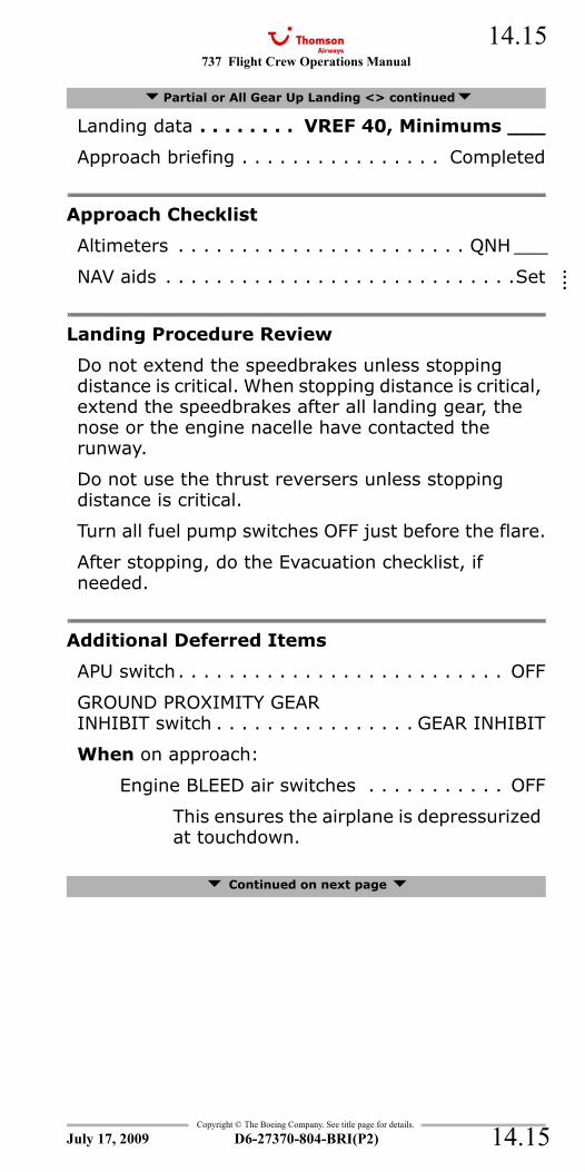
737 Flight Crew Operations Manual 14.15
Copyright © The Boeing Company. See title page for details.
D6-27370-804-BRI(P2) 14.15
Landing data . . . . . . . . VREF 40, Minimums ___
Approach briefing . . . . . . . . . . . . . . . . Completed
Approach Checklist
Altimeters . . . . . . . . . . . . . . . . . . . . . . . QNH ___
NAV aids . . . . . . . . . . . . . . . . . . . . . . . . . . . .Set
Landing Procedure Review
Do not extend the speedbrakes unless stopping distance is critical. When stopping distance is critical, extend the speedbrakes after all landing gear, the nose or the engine nacelle have contacted the runway.
Do not use the thrust reversers unless stopping distance is critical.
Turn all fuel pump switches OFF just before the flare.
After stopping, do the Evacuation checklist, if needed.
Additional Deferred Items
APU switch . . . . . . . . . . . . . . . . . . . . . . . . . . OFF
GROUND PROXIMITY GEARINHIBIT switch . . . . . . . . . . . . . . . . GEAR INHIBIT
When on approach:
Engine BLEED air switches . . . . . . . . . . . OFF
This ensures the airplane is depressurized at touchdown.
Continued on next page
Partial or All Gear Up Landing <> continued
July 17, 2009
::::
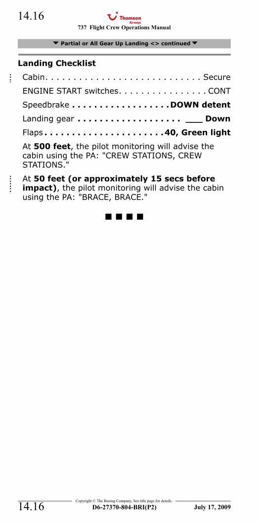
737 Flight Crew Operations Manual
Copyright © The Boeing Company. See title page for details.
D6-27370-804-BRI(P2)
14.16
14.16
Landing Checklist
Cabin. . . . . . . . . . . . . . . . . . . . . . . . . . . . Secure
ENGINE START switches. . . . . . . . . . . . . . . . CONT
Speedbrake . . . . . . . . . . . . . . . . . .DOWN detent
Landing gear . . . . . . . . . . . . . . . . . . . ___ Down
Flaps . . . . . . . . . . . . . . . . . . . . . .40, Green light
At 500 feet, the pilot monitoring will advise the cabin using the PA: "CREW STATIONS, CREW STATIONS."
At 50 feet (or approximately 15 secs before impact), the pilot monitoring will advise the cabin using the PA: "BRACE, BRACE."
WHEEL WELL FIRE 8.18
Partial or All Gear Up Landing <> continued
July 17, 2009
::::
::::
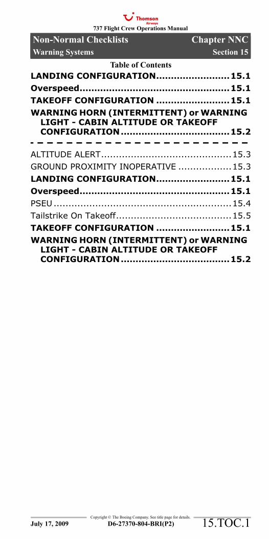
737 Flight Crew Operations Manual
Non-Normal Checklists Chapter NNCWarning Systems Section 15
Table of Contents
Copyright © The Boeing Company. See title page for details.
D6-27370-804-BRI(P2) 15.TOC.1
LANDING CONFIGURATION.........................15.1Overspeed...................................................15.1TAKEOFF CONFIGURATION .........................15.1WARNING HORN (INTERMITTENT) or WARNING
LIGHT - CABIN ALTITUDE OR TAKEOFF CONFIGURATION.....................................15.2
ALTITUDE ALERT............................................15.3GROUND PROXIMITY INOPERATIVE ..................15.3LANDING CONFIGURATION.........................15.1Overspeed...................................................15.1PSEU............................................................15.4Tailstrike On Takeoff.......................................15.5TAKEOFF CONFIGURATION .........................15.1WARNING HORN (INTERMITTENT) or WARNING
LIGHT - CABIN ALTITUDE OR TAKEOFF CONFIGURATION.....................................15.2
July 17, 2009
NNC.15-Warning SystemsTable Of Contents

737 Flight Crew Operations Manual
Non-Normal Checklists -Warning Systems
Table of Contents
Copyright © The Boeing Company. See title page for details.
D6-27370-804-BRI(P2)15.TOC.2
IntentionallyBlank
July 17, 2009
737 Flight Crew Operations Manual 15.1
Copyright © The Boeing Company. See title page for details.
D6-27370-804-BRI(P2) 15.1
NNC.15 Non-Normal Checklists-Warning Systems
1 Assure correct airplane landing configuration.- - - - - - - - - - - - - - - - - - - - - - -
1 Reduce thrust and, if needed, adjust attitude to reduce airspeed to less than Vmo/Mmo.
- - - - - - - - - - - - - - - - - - - - - - -
TAKEOFF CONFIG
1 Assure correct airplane takeoff configuration.- - - - - - - - - - - - - - - - - - - - - - -
LANDING CONFIGURATION
Condition: In flight, the steady warning horn sounds.
Overspeed
Condition: Airspeed is more than Vmo/Mmo.
TAKEOFF CONFIGURATION
TAKEOFFCONFIG
(If installed and operative)
Condition: On the ground, the intermittent cabin altitude/configuration warning horn sounds and the TAKEOFF CONFIG lights (if installed and operative) illuminate when advancing the thrust levers to takeoff thrust.
July 17, 2009
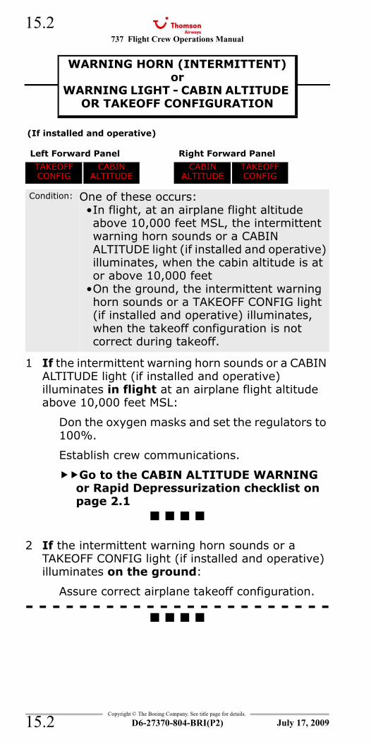
737 Flight Crew Operations Manual
Copyright © The Boeing Company. See title page for details.
D6-27370-804-BRI(P2)
15.2
15.2
1 If the intermittent warning horn sounds or a CABIN ALTITUDE light (if installed and operative) illuminates in flight at an airplane flight altitude above 10,000 feet MSL:
Don the oxygen masks and set the regulators to 100%.
Establish crew communications.
Go to the CABIN ALTITUDE WARNING or Rapid Depressurization checklist on page 2.1
2 If the intermittent warning horn sounds or a TAKEOFF CONFIG light (if installed and operative) illuminates on the ground:
Assure correct airplane takeoff configuration.- - - - - - - - - - - - - - - - - - - - - - -
WARNING HORN (INTERMITTENT)or
WARNING LIGHT - CABIN ALTITUDE OR TAKEOFF CONFIGURATION
WARNING HORN (INTERMITTENT) or WARNING LIGHT - CABIN ALTITUDEOR TAKEOFF CONFIGURATION
(If installed and operative)
Left Forward Panel Right Forward Panel
TAKEOFFCONFIG
CABIN ALTITUDE
CABINALTITUDE
TAKEOFF CONFIG
Condition: One of these occurs:•In flight, at an airplane flight altitude above 10,000 feet MSL, the intermittent warning horn sounds or a CABIN ALTITUDE light (if installed and operative) illuminates, when the cabin altitude is at or above 10,000 feet
•On the ground, the intermittent warning horn sounds or a TAKEOFF CONFIG light (if installed and operative) illuminates, when the takeoff configuration is not correct during takeoff.
July 17, 2009
737 Flight Crew Operations Manual 15.3
Copyright © The Boeing Company. See title page for details.
D6-27370-804-BRI(P2) 15.3
ALT ALERT
1 Reset the selected altitude (if needed).
2 Maintain the correct altitude.
INOP - Ground Proximity
ALTITUDE ALERT
Condition: The ALT ALERT indication shows that one of these occurs:•The airplane is about to reach the MCP altitude
•A deviation from the MCP altitude.
INOPGROUND PROXIMITY
INOPERATIVE
Condition: A ground proximity warning system fault occurs.
Note: Some or all GPWS alerts are not available. GPWS alerts which occur are valid.
July 17, 2009
737 Flight Crew Operations Manual
Copyright © The Boeing Company. See title page for details.
D6-27370-804-BRI(P2)
15.4
15.4
PSEU
G-CDZH - G-CDZM1 Do not takeoff.
G-FDZA - G-FDZS2 Choose one:
G-FDZA - G-FDZS3 Choose one:
PSEU PSEU
Condition: A proximity switch electronics unit fault occurs.
Note: The PSEU light illuminates on the ground only.
PSEU light stays illuminated when either system annunciator panel is pushed and released:
Go to step 3
PSEU light extinguishes when either system annunciator panel is pushed and released:
PSEU light stays illuminated when the parking brake is set or when both engines are shut down:
Do not takeoff.
PSEU light extinguishes when the parking brake is set or when both engines are shut down:
July 17, 2009
737 Flight Crew Operations Manual 15.5
Copyright © The Boeing Company. See title page for details.
D6-27370-804-BRI(P2) 15.5
Caution! Do not pressurize the airplane due to possible structural damage.
1 Pressurization mode selector . . . . . . . . . . . .MAN
2 Outflow VALVE switch . . . . Hold in OPEN until theoutflow VALVE position
indicates fully open
3 Plan to land at the nearest suitable airport.
Tailstrike On Takeoff
Condition: The tail hits the runway on takeoff.
July 17, 2009
737 Flight Crew Operations Manual
Copyright © The Boeing Company. See title page for details.
D6-27370-804-BRI(P2)
15.6
15.6
IntentionallyBlank
July 17, 2009
737 Flight Crew Operations Manual
Operational Information Chapter OITable of Contents Section 0
Copyright © The Boeing Company. See title page for details.
D6-27370-804-BRI(P2) OI.TOC.0.1
Introduction . . . . . . . . . . . . . . . . . . . . . . . . . . . . . . . . . . . . . . . . . .OI.1Introduction . . . . . . . . . . . . . . . . . . . . . . . . . . . . . . . . . . . . . . . . . . OI.1.1
Autoland . . . . . . . . . . . . . . . . . . . . . . . . . . . . . . . . . . . . . . . . . . . . .OI.2Autoland. . . . . . . . . . . . . . . . . . . . . . . . . . . . . . . . . . . . . . . . . . . . . OI.2.1
Cold Weather Operations . . . . . . . . . . . . . . . . . . . . . . . . . . . . . . .OI.3Cold Weather Ground Operations . . . . . . . . . . . . . . . . . . . . . . . . . OI.3.1
Cold Weather Altitude Corrections . . . . . . . . . . . . . . . . . . . . . . .OI.4Cold Weather Altitude Corrections . . . . . . . . . . . . . . . . . . . . . . . . OI.4.1
Electrical Power Up . . . . . . . . . . . . . . . . . . . . . . . . . . . . . . . . . . . .OI.5Electrical Power Up . . . . . . . . . . . . . . . . . . . . . . . . . . . . . . . . . . . . OI.5.1
Fuel Balancing . . . . . . . . . . . . . . . . . . . . . . . . . . . . . . . . . . . . . . . .OI.6Fuel Balancing . . . . . . . . . . . . . . . . . . . . . . . . . . . . . . . . . . . . . . . . OI.6.1
Bleeds Off Configuration . . . . . . . . . . . . . . . . . . . . . . . . . . . . . . . .OI.7No Engine Bleed Takeoff and Landing . . . . . . . . . . . . . . . . . . . . . OI.7.1Unpressurized Takeoff and Landing . . . . . . . . . . . . . . . . . . . . . . . OI.7.1
APU Air Unavailable . . . . . . . . . . . . . . . . . . . . . . . . . . . . . . . . . . .OI.8Starting with Ground Air Source (AC electrical power available) OI.8.1Engine Crossbleed Start. . . . . . . . . . . . . . . . . . . . . . . . . . . . . . . . . OI.8.1
July 17, 2009
Operational InformationTable Of Contents
737 Flight Crew Operations Manual
Operational Information -Table of Contents
Copyright © The Boeing Company. See title page for details.
OI.TOC.0.2 D6-27370-804-BRI(P2)
IntentionallyBlank
July 17, 2009
737 Flight Crew Operations Manual
Operational Information Chapter OIIntroduction Section 1
Copyright © The Boeing Company. See title page for details.
D6-27370-804-BRI(P2) OI.1.1
OI.1 Operational Information-IntroductionIntroductionIntroduction
IntroductionThis section of the QRH contains company Operational Procedures (OP).On the ground, the following OP should be accomplished by reference:• Electrical Power Up• No Engine Bleed Takeoff and Landing• Unpressurized Takeoff and Landing• Starting with Ground Air Source• Engine Crossbleed Start.
In-flight, the ’No Engine Bleed Takeoff and Landing’, and the ’Unpressurized Takeoff and Landing’ OP may be performed by memory, by reviewing the procedure prior to accomplishment, or by reference to the procedure during its accomplishment.In-flight, fuel balancing may be performed by memory provided the centre tank contains no fuel and a fuel leak check has been accomplished.
July 17, 2009
737 Flight Crew Operations Manual
Operational Information -Introduction
Copyright © The Boeing Company. See title page for details.
OI.1.2 D6-27370-804-BRI(P2)
IntentionallyBlank
July 17, 2009
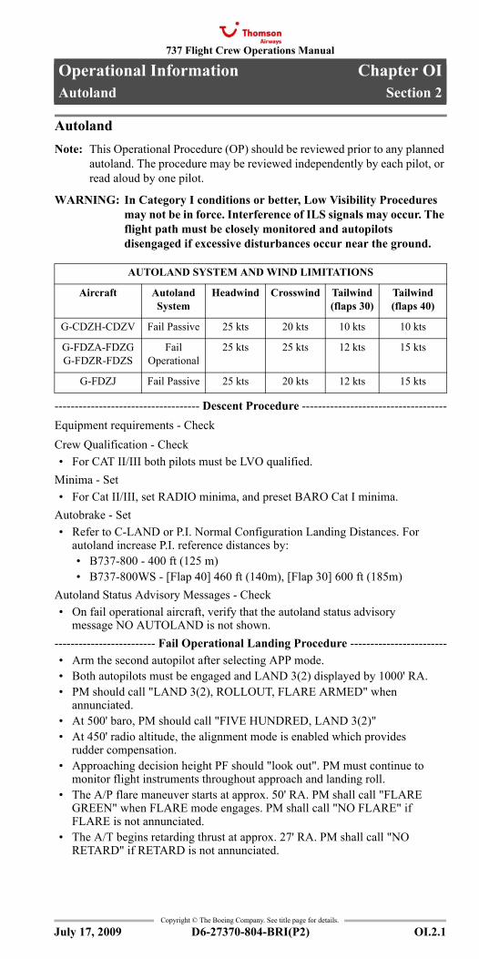
737 Flight Crew Operations Manual
Operational Information Chapter OIAutoland Section 2
Copyright © The Boeing Company. See title page for details.
D6-27370-804-BRI(P2) OI.2.1
OI.2 Operational Information-AutolandAutolandAutoland
AutolandNote: This Operational Procedure (OP) should be reviewed prior to any planned
autoland. The procedure may be reviewed independently by each pilot, or read aloud by one pilot.
WARNING: In Category I conditions or better, Low Visibility Procedures may not be in force. Interference of ILS signals may occur. The flight path must be closely monitored and autopilots disengaged if excessive disturbances occur near the ground.
------------------------------------ Descent Procedure ------------------------------------Equipment requirements - CheckCrew Qualification - Check• For CAT II/III both pilots must be LVO qualified.
Minima - Set• For Cat II/III, set RADIO minima, and preset BARO Cat I minima.
Autobrake - Set• Refer to C-LAND or P.I. Normal Configuration Landing Distances. For
autoland increase P.I. reference distances by:• B737-800 - 400 ft (125 m)• B737-800WS - [Flap 40] 460 ft (140m), [Flap 30] 600 ft (185m)
Autoland Status Advisory Messages - Check• On fail operational aircraft, verify that the autoland status advisory
message NO AUTOLAND is not shown.------------------------- Fail Operational Landing Procedure ------------------------• Arm the second autopilot after selecting APP mode.• Both autopilots must be engaged and LAND 3(2) displayed by 1000' RA.• PM should call "LAND 3(2), ROLLOUT, FLARE ARMED" when
annunciated.• At 500' baro, PM should call "FIVE HUNDRED, LAND 3(2)"• At 450' radio altitude, the alignment mode is enabled which provides
rudder compensation.• Approaching decision height PF should "look out". PM must continue to
monitor flight instruments throughout approach and landing roll.• The A/P flare maneuver starts at approx. 50' RA. PM shall call "FLARE
GREEN" when FLARE mode engages. PM shall call "NO FLARE" if FLARE is not annunciated.
• The A/T begins retarding thrust at approx. 27' RA. PM shall call "NO RETARD" if RETARD is not annunciated.
AUTOLAND SYSTEM AND WIND LIMITATIONS
Aircraft Autoland System
Headwind Crosswind Tailwind(flaps 30)
Tailwind(flaps 40)
G-CDZH-CDZV Fail Passive 25 kts 20 kts 10 kts 10 kts
G-FDZA-FDZGG-FDZR-FDZS
Fail Operational
25 kts 25 kts 12 kts 15 kts
G-FDZJ Fail Passive 25 kts 20 kts 12 kts 15 kts
July 17, 2009
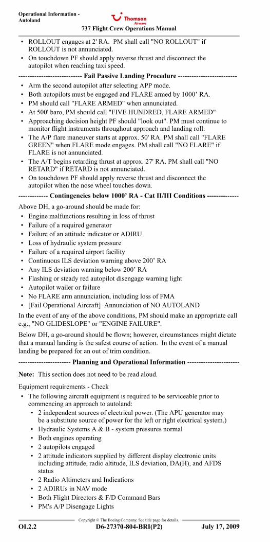
737 Flight Crew Operations Manual
Operational Information -Autoland
Copyright © The Boeing Company. See title page for details.
OI.2.2 D6-27370-804-BRI(P2)
• ROLLOUT engages at 2' RA. PM shall call "NO ROLLOUT" if ROLLOUT is not annunciated.
• On touchdown PF should apply reverse thrust and disconnect the autopilot when reaching taxi speed.
---------------------------- Fail Passive Landing Procedure --------------------------• Arm the second autopilot after selecting APP mode.• Both autopilots must be engaged and FLARE armed by 1000’ RA.• PM should call "FLARE ARMED" when annunciated.• At 500' baro, PM should call "FIVE HUNDRED, FLARE ARMED"• Approaching decision height PF should "look out". PM must continue to
monitor flight instruments throughout approach and landing roll.• The A/P flare maneuver starts at approx. 50' RA. PM shall call "FLARE
GREEN" when FLARE mode engages. PM shall call "NO FLARE" if FLARE is not annunciated.
• The A/T begins retarding thrust at approx. 27' RA. PM shall call "NO RETARD" if RETARD is not annunciated.
• On touchdown PF should apply reverse thrust and disconnect the autopilot when the nose wheel touches down.
------------- Contingencies below 1000’ RA - Cat II/III Conditions --------------Above DH, a go-around should be made for:• Engine malfunctions resulting in loss of thrust• Failure of a required generator• Failure of an attitude indicator or ADIRU• Loss of hydraulic system pressure• Failure of a required airport facility• Continuous ILS deviation warning above 200’ RA• Any ILS deviation warning below 200’ RA• Flashing or steady red autopilot disengage warning light• Autopilot wailer or failure• No FLARE arm annunciation, including loss of FMA• [Fail Operational Aircraft] Annunciation of NO AUTOLAND
In the event of any of the above conditions, PM should make an appropriate call e.g., "NO GLIDESLOPE" or "ENGINE FAILURE". Below DH, a go-around should be flown; however, circumstances might dictate that a manual landing is the safest course of action. In the event of a manual landing be prepared for an out of trim condition.----------------------- Planning and Operational Information -----------------------
Note: This section does not need to be read aloud.
Equipment requirements - Check• The following aircraft equipment is required to be serviceable prior to
commencing an approach to autoland:• 2 independent sources of electrical power. (The APU generator may
be a substitute source of power for the left or right electrical system.)• Hydraulic Systems A & B - system pressures normal• Both engines operating• 2 autopilots engaged• 2 attitude indicators supplied by different display electronic units
including attitude, radio altitude, ILS deviation, DA(H), and AFDS status
• 2 Radio Altimeters and Indications• 2 ADIRUs in NAV mode• Both Flight Directors & F/D Command Bars• PM's A/P Disengage Lights
July 17, 2009
737 Flight Crew Operations Manual
Operational Information -Autoland
Copyright © The Boeing Company. See title page for details.
D6-27370-804-BRI(P2) OI.2.3
• A/P Disengage Aural Warning• Thrust Mode Annunciation• Both pilots’ Flight Mode Annunciations• Both ILS Receivers and pointers• Radio DH displayed on both PFDs (for Cat II/IIIA only))• EGPWS Automatic Height Callouts (for Cat IIIA only)• Windshield Wipers (for Cat II/IIIA on Fail Passive aircraft only)
Landing Performance - Check• Prior to dispatch to a destination predicated on Cat II/III conditions, check
C-LAND (Autolanding), or make the following Autoland corrections to the PD Landing Field Length Limit:• B737-800 - subtract 400 ft (125m) from Field Length available.• B737-800WS - subtract [Flap 40] 460 ft (140m), [Flap 30] 600 ft
(185m) from Field Length available.Minima / ILS status - Refer to OMC Flight Guide• For CAT I/II autoland, ILS Runway must be listed as suitable for autoland
in Company Procedures pages. For Cat III, runway must be listed in Company Procedures pages. Refer to specific approach plate for minima.
• Training Captains are authorized to perform Verification Autolands at Cat I/II/III runways not listed in the Company Procedures pages.
• [Fail Operational] Autoland and rollout may be accomplished with either ASA LAND 3 or LAND 2 displayed. There is no change to minima with autoland status advisory message NO LAND 3, or ASA LAND 2 displayed.
Controlling RVR - Check• Touchdown RVR (or Mid-point RVR if Touchdown not available) is
required for Cat II and Cat IIIA and is controlling.• “Controlling Runway Visual Range" is the value relevant to the approach
ban requirements. The approach shall not be continued beyond the outer marker, or equivalent position, if the controlling RVR is below that required for the approach being flown.
• In the absence of an outer marker, or equivalent position, use 1000 aal.• If reported and relevant a Mid-point RVR value of 125 m and a Stop-end
RVR value of 75 m are also controlling.• Relevant, in this context, means that part of the runway used during the
high speed phase of landing down to a speed of approximately 60 kts.Limitations - Check• Instrument switching is not permitted.• Autoland above Maximum Landing Mass is not certified.• A planned Cat II/III approach with a manual landing is not authorized.• Operations in conditions below Category IIIA are not approved.• Autoland is only approved with flaps 30 or 40. Flaps 40 is recommended
if weather conditions are below Category I.• The maximum and minimum glideslope angles are 3.25° and 2.50°
respectively. The localizer must not be offset.FMA calls - Review• After glideslope capture FMA calls should be made by PM.• FMA calls are not required for "RETARD" or "ROLLOUT".
July 17, 2009
737 Flight Crew Operations Manual
Operational Information -Autoland
Copyright © The Boeing Company. See title page for details.
OI.2.4 D6-27370-804-BRI(P2)
IntentionallyBlank
July 17, 2009
737 Flight Crew Operations Manual
Operational Information Chapter OICold Weather Operations Section 3
Copyright © The Boeing Company. See title page for details.
D6-27370-804-BRI(P2) OI.3.1
OI.3 Operational Information-Cold Weather OperationsCold Weather OperationsCold Weather Operations
Cold Weather Ground OperationsNote: This Operational Procedure (OP) should be accomplished when required
in conjunction with the appropriate Normal Procedure. Review each OP section BEFORE performing the related NP. Refer to OMB Supplementary Procedures "Adverse Weather" for full details on all cold weather procedures.
----------------------------------- Exterior Inspection ------------------------------------Do the normal Exterior Inspection with the following additional steps:• Surfaces - Check
• Cold-soaked fuel frost: refer to OMB Supplementary Procedures section 3. Thin hoarfrost on upper fuselage is acceptable, vents and ports must be clear. For full details refer to Supplementary Procedures "Adverse Weather".
• Control balance cavities - Check after snow removal• Pitot probes and static ports - Check• Air-cond inlets & exits, APU inlet, fuel tank vents, ldg gear doors - Check• Engines inlet cowlings and fan blades - Free of snow and ice / Fan free to
rotate• Outflow valve- Check fully open
---------------------------------------- Preflight --------------------------------------------Do the following step after completing the normal Preflight procedure:• PITOT HEAT switches - ON
---------------------------------- Takeoff performance -----------------------------------Review the following items after completing the takeoff briefing:• Max crosswind - Review• Takeoff thrust - Full, or derate if runway contaminated
• Do not use ATM if runway is contaminated.• Takeoff flap - Review
• Use highest practicable setting if runway is contaminated.• Takeoff bleed configuration - Review
• If the aircraft has been de-iced and Bleeds OFF takeoff is required, use “Unpressurized T/O” Procedure.
July 17, 2009
737 Flight Crew Operations Manual
Operational Information -Cold Weather Operations
Copyright © The Boeing Company. See title page for details.
OI.3.2 D6-27370-804-BRI(P2)
----------------------------------- On Stand De-icing -------------------------------------Perform the following procedure for on stand de-icing with engines shutdown:• Cabin crew and passengers - Advise• APU - OFF / if ON: advise ground personnel
• Operate the APU during de-icing only if necessary. If the APU is running, ingestion of de-icing fluid causes objectionable fumes and odors to enter the airplane.
• Flaps - UP• Stabilizer trim - Full APL NOSE DOWN (manual limit)• APU bleed air switch - OFF• Start time, fluid type, mixture - Note• Holdover time - Check
After de-icing:• Stabilizer trim - ___ units• APU (if required) - Start• APU bleed air switch - ON
• Wait a minimum of 1 minute before switching APU bleed ON.---------------------------------------- Engine start ----------------------------------------Do the normal Engine Start procedure with the following modifications:
CAUTION: When OAT is below -35ºC, additional procedures apply.
• Pushback before engine start - Consider on slippery apron• Oil pressure - Check
• Any indication above zero after idle RPM is reached is acceptable. Up to three and one-half minutes may be allowed for oil pressure to reach the minimum operating pressure. During this period, the LOW OIL PRESSURE light may remain illuminated, pressure may go above the normal range and the FILTER BYPASS light may illuminate. Operate the engine at idle thrust until oil pressure returns to the normal range.
• DUs - May require additional warm-up time---------------------------------------- Before taxi -----------------------------------------Do the normal Before Taxi procedure with the following modifications:• Generator drives - Stabilized in maximum 5 min.• Wing A/I - ON
• Unless airplane is, or will be protected with Type II or Type IV fluid.
Note: Delay “no bleed” setup until just prior T/O if wing AI is required.
• Flaps - Check full travel (up --> Flaps 40 --> up)• Check full travel if temperature below 0°C or aircraft has been
de-iced; then set as needed.
CAUTION: In case of remote de-icing, do not move flaps until afterde-icing is completed.
• Flaps - UP if TWY is contaminated• If taxi route is through slush, or standing water in low
temperatures, or if precipitation is falling with temperatures below freezing, taxi out with the flaps up.
• Flight controls - Check
CAUTION: In case of remote de-icing, do not move flight controlsuntil after de-icing is completed.
• Before Taxi checklist - Complete
July 17, 2009
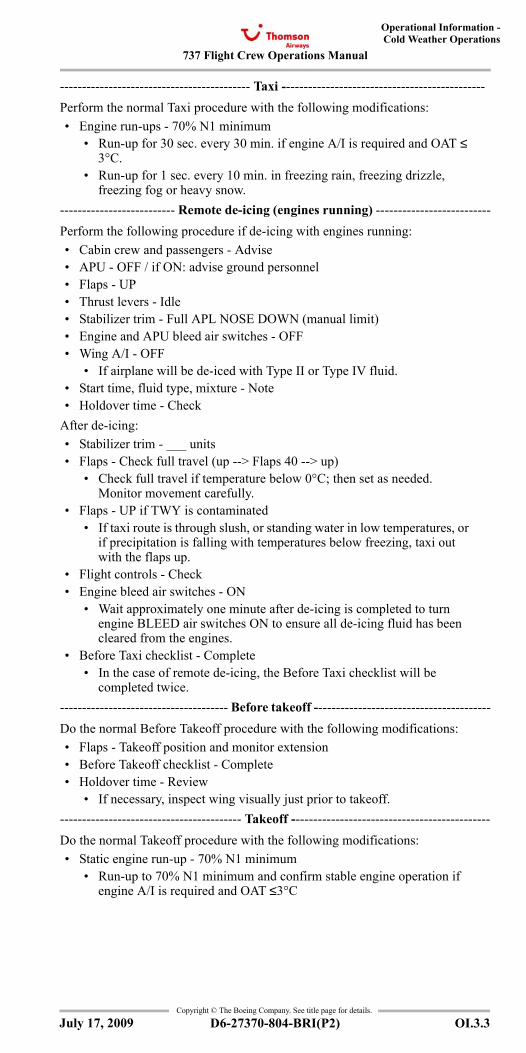
737 Flight Crew Operations Manual
Operational Information -Cold Weather Operations
Copyright © The Boeing Company. See title page for details.
D6-27370-804-BRI(P2) OI.3.3
------------------------------------------- Taxi ----------------------------------------------Perform the normal Taxi procedure with the following modifications:• Engine run-ups - 70% N1 minimum
• Run-up for 30 sec. every 30 min. if engine A/I is required and OAT ≤ 3°C.
• Run-up for 1 sec. every 10 min. in freezing rain, freezing drizzle, freezing fog or heavy snow.
-------------------------- Remote de-icing (engines running) --------------------------Perform the following procedure if de-icing with engines running:• Cabin crew and passengers - Advise• APU - OFF / if ON: advise ground personnel• Flaps - UP• Thrust levers - Idle• Stabilizer trim - Full APL NOSE DOWN (manual limit)• Engine and APU bleed air switches - OFF• Wing A/I - OFF
• If airplane will be de-iced with Type II or Type IV fluid.• Start time, fluid type, mixture - Note• Holdover time - Check
After de-icing:• Stabilizer trim - ___ units• Flaps - Check full travel (up --> Flaps 40 --> up)
• Check full travel if temperature below 0°C; then set as needed. Monitor movement carefully.
• Flaps - UP if TWY is contaminated• If taxi route is through slush, or standing water in low temperatures, or
if precipitation is falling with temperatures below freezing, taxi out with the flaps up.
• Flight controls - Check• Engine bleed air switches - ON
• Wait approximately one minute after de-icing is completed to turn engine BLEED air switches ON to ensure all de-icing fluid has been cleared from the engines.
• Before Taxi checklist - Complete• In the case of remote de-icing, the Before Taxi checklist will be
completed twice.-------------------------------------- Before takeoff ----------------------------------------Do the normal Before Takeoff procedure with the following modifications:• Flaps - Takeoff position and monitor extension• Before Takeoff checklist - Complete• Holdover time - Review
• If necessary, inspect wing visually just prior to takeoff.----------------------------------------- Takeoff ---------------------------------------------Do the normal Takeoff procedure with the following modifications:• Static engine run-up - 70% N1 minimum
• Run-up to 70% N1 minimum and confirm stable engine operation if engine A/I is required and OAT ≤3°C
July 17, 2009
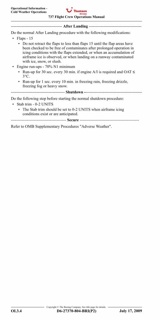
737 Flight Crew Operations Manual
Operational Information -Cold Weather Operations
Copyright © The Boeing Company. See title page for details.
OI.3.4 D6-27370-804-BRI(P2)
-------------------------------------- After Landing ---------------------------------------Do the normal After Landing procedure with the following modifications:• Flaps - 15
• Do not retract the flaps to less than flaps 15 until the flap areas have been checked to be free of contaminates after prolonged operation in icing conditions with the flaps extended, or when an accumulation of airframe ice is observed, or when landing on a runway contaminated with ice, snow, or slush.
• Engine run-ups - 70% N1 minimum• Run-up for 30 sec. every 30 min. if engine A/I is required and OAT ≤
3°C.• Run-up for 1 sec. every 10 min. in freezing rain, freezing drizzle,
freezing fog or heavy snow.---------------------------------------- Shutdown -------------------------------------------Do the following step before starting the normal shutdown procedure:• Stab trim - 0-2 UNITS
• The Stab trim should be set to 0-2 UNITS when airframe icing conditions exist or are anticipated.
----------------------------------------- Secure --------------------------------------------Refer to OMB Supplementary Procedures "Adverse Weather".
July 17, 2009
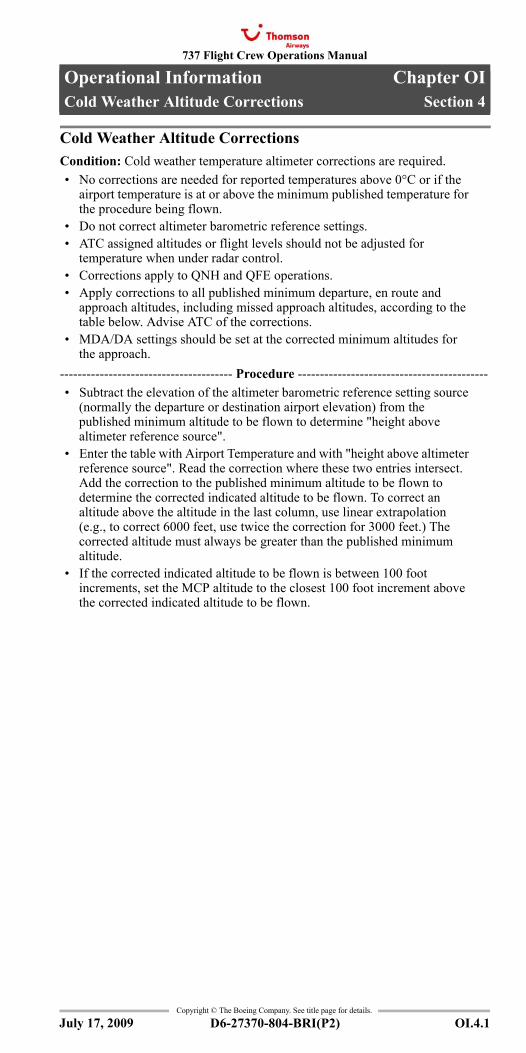
737 Flight Crew Operations Manual
Operational Information Chapter OICold Weather Altitude Corrections Section 4
Copyright © The Boeing Company. See title page for details.
D6-27370-804-BRI(P2) OI.4.1
OI.4 Operational Information-Cold Weather Altitude CorrectionsCold Weather Altitude CorrectionsCold Weather Altitude Corrections
Cold Weather Altitude CorrectionsCondition: Cold weather temperature altimeter corrections are required.• No corrections are needed for reported temperatures above 0°C or if the
airport temperature is at or above the minimum published temperature for the procedure being flown.
• Do not correct altimeter barometric reference settings.• ATC assigned altitudes or flight levels should not be adjusted for
temperature when under radar control.• Corrections apply to QNH and QFE operations.• Apply corrections to all published minimum departure, en route and
approach altitudes, including missed approach altitudes, according to the table below. Advise ATC of the corrections.
• MDA/DA settings should be set at the corrected minimum altitudes for the approach.
--------------------------------------- Procedure -------------------------------------------• Subtract the elevation of the altimeter barometric reference setting source
(normally the departure or destination airport elevation) from the published minimum altitude to be flown to determine "height above altimeter reference source".
• Enter the table with Airport Temperature and with "height above altimeter reference source". Read the correction where these two entries intersect. Add the correction to the published minimum altitude to be flown to determine the corrected indicated altitude to be flown. To correct an altitude above the altitude in the last column, use linear extrapolation (e.g., to correct 6000 feet, use twice the correction for 3000 feet.) The corrected altitude must always be greater than the published minimum altitude.
• If the corrected indicated altitude to be flown is between 100 foot increments, set the MCP altitude to the closest 100 foot increment above the corrected indicated altitude to be flown.
July 17, 2009
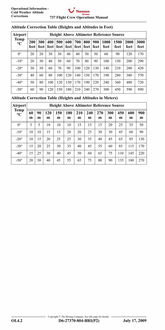
737 Flight Crew Operations Manual
Operational Information -Cold Weather Altitude Corrections
Copyright © The Boeing Company. See title page for details.
OI.4.2 D6-27370-804-BRI(P2)
Altitude Correction Table (Heights and Altitudes in Feet)
Altitude Correction Table (Heights and Altitudes in Meters)
Airport Temp
°C
Height Above Altimeter Reference Source
200 feet
300 feet
400 feet
500 feet
600 feet
700 feet
800 feet
900 feet
1000 feet
1500 feet
2000 feet
3000 feet
0° 20 20 30 30 40 40 50 50 60 90 120 170
-10° 20 30 40 50 60 70 80 90 100 150 200 290
-20° 30 50 60 70 90 100 120 130 140 210 280 420
-30° 40 60 80 100 120 140 150 170 190 280 380 570
-40° 50 80 100 120 150 170 190 220 240 360 480 720
-50° 60 90 120 150 180 210 240 270 300 450 590 890
Airport Temp
°C
Height Above Altimeter Reference Source
60 m
90 m
120 m
150 m
180 m
210 m
240 m
270 m
300 m
450 m
600 m
900 m
0° 5 5 10 10 10 15 15 15 20 25 35 50
-10° 10 10 15 15 20 20 25 30 30 45 60 90
-20° 10 15 20 25 25 30 35 40 45 65 85 130
-30° 15 20 25 30 35 40 45 55 60 85 115 170
-40° 15 25 30 40 45 50 60 65 75 110 145 220
-50° 20 30 40 45 55 65 75 80 90 135 180 270
July 17, 2009
737 Flight Crew Operations Manual
Operational Information Chapter OIElectrical Power Up Section 5
Copyright © The Boeing Company. See title page for details.
D6-27370-804-BRI(P2) OI.5.1
OI.5 Operational Information-Electrical Power UpElectrical Power UpElectrical Power Up
Electrical Power UpThe following procedure is accomplished to permit safe application of electrical power.
G-FDZA - G-FDZSNote: Devices plugged into the flight deck auxiliary power outlets during
Electrical Power Up will not be powered until the plugs are removed and re-inserted.
• BATTERY switch - Guard closed• STANDBY POWER switch - Guard closed• ALTERNATE FLAPS master switch - Guard closed• Windshield WIPER selector(s) - PARK• ELECTRIC HYDRAULIC PUMPS switches - OFF• LANDING GEAR lever- DN
• Verify that the green landing gear indicator lights are illuminated.• Verify that the red landing gear indicator lights are extinguished.
If external power is needed:• Verify that the GRD POWER AVAILABLE light is illuminated.• GRD POWER switch - ON
• Verify that the SOURCE OFF lights are extinguished.• Verify that the TRANSFER BUS OFF lights are extinguished.• Verify that the STANDBY PWR OFF lights are extinguished.
If APU power is needed:• Verify that the engine No. 1, APU and the engine No. 2 fire switches are
in.• Alert ground personnel before the following test is accomplished.• OVERHEAT DETECTOR switches – NORMAL• TEST switch – Hold to FAULT/INOP
• Verify that the MASTER CAUTION lights are illuminated.• Verify that the OVHT/DET annunciator is illuminated.• Verify that the FAULT light is illuminated.
• If the FAULT light fails to illuminate, the fault monitoring system is inoperative.
• Verify that the APU DET INOP light is illuminated.• Do not operate the APU if the APU DET INOP light fails to
illuminate.• TEST switch – Hold to OVHT/FIRE
• Verify that the fire warning bell sounds.• Verify that the master FIRE WARN lights are illuminated.• Verify that the MASTER CAUTION lights are illuminated.• Verify that the OVHT/DET annunciator is illuminated.• Master FIRE WARN light – Push
• Verify that the master FIRE WARN lights are extinguished.• Verify that the fire warning bell cancels.
• Verify that the engine No. 1, APU and the engine No. 2 fire switches stay illuminated.
• Verify that the ENG 1 OVERHEAT and ENG 2 OVERHEAT lights stay illuminated.
July 17, 2009
737 Flight Crew Operations Manual
Operational Information -Electrical Power Up
Copyright © The Boeing Company. See title page for details.
OI.5.2 D6-27370-804-BRI(P2)
• Extinguisher test switch – Check• TEST switch - Position to 1 and hold
• Verify that the three green extinguisher test lights are illuminated.• TEST switch - Release
• Verify that the three green extinguisher test lights are extinguished.• Repeat for test position 2.
• APU - Start and on bus
Note: If extended APU operation is needed on the ground, position an AC operated fuel pump ON. If fuel is loaded in the center tank, position the left center tank fuel pump switch ON to prevent a fuel imbalance before takeoff.
CAUTION: Center tank fuel pump switches should be positionedON only if the fuel quantity in the center tank exceeds 453kgs.
CAUTION: Do not operate the center tank fuel pumps with theflight deck unattended.
Note: Whenever the APU is operating and AC electrical power is on the airplane busses, operate at least one fuel boost pump to supply fuel under pressure to the APU to extend the service life of the APU fuel control unit.
• When the APU GEN OFF BUS light is illuminated:• APU GENERATOR bus switches - ON• Verify that the SOURCE OFF lights are extinguished.• Verify that the TRANSFER BUS OFF lights are extinguished.• Verify that the STANDBY PWR OFF light is extinguished.
• Verify that the APU MAINT light is extinguished.• Verify that the APU LOW OIL PRESSURE light is extinguished.• Verify that the APU FAULT light is extinguished.• Verify that the APU OVERSPEED light is extinguished.
• Wheel well fire warning system - Test• Test switch – Hold to OVHT/FIRE
• Verify that the fire warning bell sounds.• Verify that the master FIRE WARN lights are illuminated.• Verify that the MASTER CAUTION lights are illuminated.• Verify that the OVHT/DET annunciator is illuminated.
• Fire warning BELL CUTOUT switch – Push• Verify that the master FIRE WARN lights are extinguished.• Verify that the fire warning bell cancels.• Verify that the WHEEL WELL light stays illuminated.
July 17, 2009
737 Flight Crew Operations Manual
Operational Information Chapter OIFuel Balancing Section 6
Copyright © The Boeing Company. See title page for details.
D6-27370-804-BRI(P2) OI.6.1
OI.6 Operational Information-Fuel BalancingFuel BalancingFuel Balancing
Fuel BalancingIf an engine fuel leak is suspected:• Accomplish the ENGINE FUEL LEAK Checklist.
Maintain main tank No. 1 and No. 2 fuel balance within limitations.
Note: Fuel pump pressure should be supplied to the engines at all times. At high altitude, without fuel pump pressure, thrust deterioration or engine flameout may occur.
If the center tank contains fuel:• Center tank fuel pump switches - OFF
Note: Fuel CONFIG indication may be displayed with fuel in the center tank.
• Crossfeed selector - Open• Fuel pump switches (low tank) - OFF• When quantities are balanced:
• Fuel pump switches (main tank) - ON• Center tank fuel pump switches - ON• Crossfeed selector - Close
If the center tank contains no fuel:• Crossfeed selector - Open• Fuel pump switches (low tank) - OFF• When quantities are balanced:
• Fuel pump switches - ON• Crossfeed selector - Close
July 17, 2009
737 Flight Crew Operations Manual
Operational Information -Fuel Balancing
Copyright © The Boeing Company. See title page for details.
OI.6.2 D6-27370-804-BRI(P2)
IntentionallyBlank
July 17, 2009
737 Flight Crew Operations Manual
Operational Information Chapter OIBleeds Off Configuration Section 7
Copyright © The Boeing Company. See title page for details.
D6-27370-804-BRI(P2) OI.7.1
OI.7 Operational Information-Bleeds Off ConfigurationBleeds Off ConfigurationBleeds Off Configuration
No Engine Bleed Takeoff and LandingWhen making a no engine bleed takeoff or landing with the APU operating:------------------------------------------ Takeoff -------------------------------------------
Note: If anti–ice is required for taxi, configure for a “No Engine Bleed Takeoff” just prior to takeoff.
Note: If anti–ice is not required for taxi, configure for a “No Engine Bleed Takeoff” just after engine start.
• Right PACK switch - AUTO• ISOLATION VALVE switch - CLOSE• Left PACK switch - AUTO• Engine No. 1 BLEED air switch - OFF• APU BLEED air switch - ON• Engine No. 2 BLEED air switch - OFF• WING ANTI-ICE switch - OFF
• The WING ANTI-ICE switch must remain OFF until the engine BLEED air switches are repositioned to ON and the ISOLATION VALVE switch is repositioned to AUTO.
-------------------------------------- After takeoff -----------------------------------------
Note: If engine failure occurs, do not position engine BLEED air switches ON until reaching 1500 feet or until obstacle clearance height has been attained.
• Engine No. 2 BLEED air switch - ON• APU BLEED air switch - OFF• When CABIN rate of CLIMB indicator stabilizes:
• Engine No. 1 BLEED air switch - ON• ISOLATION VALVE switch - AUTO
----------------------------------------- Landing --------------------------------------------• If additional go-around thrust is desired configure for a “No Engine Bleed
Landing.”• When below 10,000 feet:
• WING ANTI-ICE switch - OFF• Right PACK switch - AUTO• ISOLATION VALVE switch - CLOSE• Left PACK switch - AUTO• Engine No. 1 BLEED air switch - OFF• APU BLEED air switch - ON• Engine No. 2 BLEED air switch - OFF
Unpressurized Takeoff and LandingWhen making a no engine bleed takeoff or landing with the APU inoperative:------------------------------------------ Takeoff -------------------------------------------• PACK switches - AUTO• ISOLATION VALVE switch - CLOSE• Engine BLEED air switches - OFF
July 17, 2009
737 Flight Crew Operations Manual
Operational Information -Bleeds Off Configuration
Copyright © The Boeing Company. See title page for details.
OI.7.2 D6-27370-804-BRI(P2)
-------------------------------------- After takeoff -----------------------------------------
Note: If engine failure occurs, do not position engine BLEED air switches ON until reaching 1500 feet or until obstacle clearance height has been attained.
• At not less than 400 feet, and prior to 2000 feet above field elevation:• Engine No. 2 BLEED air switch - ON
• When CABIN rate of CLIMB indicator stabilizes:• Engine No. 1 BLEED air switch - ON• ISOLATION VALVE switch - AUTO
----------------------------------------- Landing --------------------------------------------• When below 10,000 feet and starting the turn to final approach:
• Engine BLEED air switches - OFF• Avoid high rates of descent for passenger comfort.
July 17, 2009
737 Flight Crew Operations Manual
Operational Information Chapter OIAPU Air Unavailable Section 8
Copyright © The Boeing Company. See title page for details.
D6-27370-804-BRI(P2) OI.8.1
OI.8 Operational Information-APU Air UnavailableAPU Air UnavailableAPU Air Unavailable
Starting with Ground Air Source (AC electrical power available)Engine No.1 must be started first, unless ground crew instruct otherwise.• When cleared to start:
• APU BLEED air switch - OFF• Engine No. 1 start - Accomplish
• Use normal start procedures.• After engine start, select generator switch ON, and GRD PWR
OFF.
WARNING: To minimize the hazard to ground personnel, the external air should be disconnected, and the second engine started using the Engine Crossbleed Start procedure.
Engine Crossbleed StartPrior to using this procedure, ensure that the area to the rear is clear.• Engine BLEED air switches - ON• APU BLEED air switch - OFF• PACK switches - OFF• ISOLATION VALVE switch - AUTO
• Ensures bleed air supply for engine start.• Engine thrust lever (operating engine) - Advance thrust lever until bleed
duct pressure indicates 30 psi• Non-operating engine - Start
• Use normal start procedures with crossbleed air.• After starter cutout, adjust thrust on both engines, as required.
July 17, 2009

737 Flight Crew Operations Manual
Operational Information -APU Air Unavailable
Copyright © The Boeing Company. See title page for details.
OI.8.2 D6-27370-804-BRI(P2)
IntentionallyBlank
July 17, 2009

737 Flight Crew Operations Manual
Performance Inflight - QRH Chapter PI-QRHTable of Contents
Copyright © The Boeing Company. See title page for details.
D6-27370-804-BRI(P2) PI-QRH.TOC.1
737-800 CFM56-7B27 KG JAA CATC/N - - - - PI-QRH.10.1737-800WSFP1 CFM56-7B27 KG JAA CATC/N (FMC Mod-el 737-800W.1) - - - - - - - - - - - - - - - - - - - - - - PI-QRH.20.1
July 17, 2009
Performance Inflight - QRH
Performance Inflight - QRH
737 Flight Crew Operations Manual
Copyright © The Boeing Company. See title page for details.
PI-QRH.TOC.2 D6-27370-804-BRI(P2)
Performance Inflight - QRH -Table of Contents
IntentionallyBlank
July 17, 2009
737 Flight Crew Operations Manual
Performance Inflight - QRH Chapter PI-QRHTable of Contents Section 10
Copyright © The Boeing Company. See title page for details.
D6-27370-804-BRI(P2) PI-QRH.TOC.10.1
737-800 CFM56-7B27 KG JAA CATC/N
737-800 CFM56-7B27 KG JAA CATC/N
General . . . . . . . . . . . . . . . . . . . . . . . . . . . . . . . . . . . . . . . PI-QRH.10.1
Flight With Unreliable Airspeed/ Turbulent Air Penetration . . . . . . . . . . . . . . . . . . . . . PI-QRH.10.1Max Climb %N1 . . . . . . . . . . . . . . . . . . . . . . . . . . . . . PI-QRH.10.3Go-around %N1 . . . . . . . . . . . . . . . . . . . . . . . . . . . . . PI-QRH.10.3VREF . . . . . . . . . . . . . . . . . . . . . . . . . . . . . . . . . . . . . PI-QRH.10.4
Advisory Information . . . . . . . . . . . . . . . . . . . . . . . . . . . . PI-QRH.11.1Normal Configuration Landing Distances . . . . . . . . . . PI-QRH.11.1Non-Normal Configuration Landing Distance . . . . . . . PI-QRH.11.3Recommended Brake Cooling Schedule . . . . . . . . . . PI-QRH.11.11
Engine Inoperative . . . . . . . . . . . . . . . . . . . . . . . . . . . . . . PI-QRH.12.1Initial Max Continuous %N1 . . . . . . . . . . . . . . . . . . . PI-QRH.12.1Max Continuous %N1 . . . . . . . . . . . . . . . . . . . . . . . . PI-QRH.12.2Driftdown Speed/Level Off Altitude . . . . . . . . . . . . . PI-QRH.12.6Driftdown/LRC Cruise Range Capability . . . . . . . . . PI-QRH.12.7Long Range Cruise Altitude Capability . . . . . . . . . . . PI-QRH.12.7Long Range Cruise Control . . . . . . . . . . . . . . . . . . . . PI-QRH.12.8Long Range Cruise Diversion Fuel and Time . . . . . . PI-QRH.12.9Holding . . . . . . . . . . . . . . . . . . . . . . . . . . . . . . . . . . . PI-QRH.12.10
Gear Down . . . . . . . . . . . . . . . . . . . . . . . . . . . . . . . . . . . . PI-QRH.13.1Long Range Cruise Altitude Capability . . . . . . . . . . . PI-QRH.13.1Long Range Cruise Control . . . . . . . . . . . . . . . . . . . . PI-QRH.13.1Long Range Cruise Enroute Fuel and Time . . . . . . . . PI-QRH.13.2Descent . . . . . . . . . . . . . . . . . . . . . . . . . . . . . . . . . . . . PI-QRH.13.2Holding . . . . . . . . . . . . . . . . . . . . . . . . . . . . . . . . . . . . PI-QRH.13.3
Gear Down, Engine Inoperative . . . . . . . . . . . . . . . . . . . PI-QRH.14.1Driftdown Speed/Level Off Altitude . . . . . . . . . . . . . PI-QRH.14.1Long Range Cruise Altitude Capability . . . . . . . . . . . PI-QRH.14.1Long Range Cruise Control . . . . . . . . . . . . . . . . . . . . PI-QRH.14.1Long Range Cruise Diversion Fuel and Time . . . . . . PI-QRH.14.2Holding . . . . . . . . . . . . . . . . . . . . . . . . . . . . . . . . . . . . PI-QRH.14.3
Text . . . . . . . . . . . . . . . . . . . . . . . . . . . . . . . . . . . . . . . . . . . PI-QRH.15.1Introduction . . . . . . . . . . . . . . . . . . . . . . . . . . . . . . . . PI-QRH.15.1General . . . . . . . . . . . . . . . . . . . . . . . . . . . . . . . . . . . . PI-QRH.15.1Advisory Information . . . . . . . . . . . . . . . . . . . . . . . . . PI-QRH.15.1Engine Inoperative . . . . . . . . . . . . . . . . . . . . . . . . . . . PI-QRH.15.3Gear Down . . . . . . . . . . . . . . . . . . . . . . . . . . . . . . . . . PI-QRH.15.4
July 17, 2009
737-800 CFM56-7B27 KG JAA CATC/NTable of Contents
737 Flight Crew Operations Manual
Copyright © The Boeing Company. See title page for details.
PI-QRH.TOC.10.2 D6-27370-804-BRI(P2)
Performance Inflight - QRH -Table of Contents
IntentionallyBlank
July 17, 2009
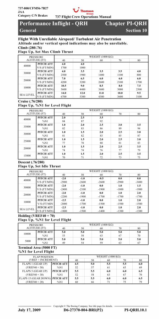
737 Flight Crew Operations Manual
Performance Inflight - QRH Chapter PI-QRHGeneral Section 10
737-800/CFM56-7B27JAACategory C/N Brakes
Copyright © The Boeing Company. See title page for details.
D6-27370-804-BRI(P2) PI-QRH.10.1
PI-QRH.10 Performance Inflight - QRH-GeneralGeneral
Flight With Unreliable Airspeed/ Turbulent Air PenetrationAltitude and/or vertical speed indications may also be unreliable. Climb (280/.76) Flaps Up, Set Max Climb Thrust
Cruise (.76/280)Flaps Up, %N1 for Level Flight
Descent (.76/280)Flaps Up, Set Idle Thrust
Holding (VREF40 + 70)Flaps Up, %N1 for Level Flight
Terminal Area (5000 FT)%N1 for Level Flight
PRESSURE ALTITUDE (FT)
WEIGHT (1000 KG)40 50 60 70 80
40000 PITCH ATT 4.0 4.0V/S (FT/MIN) 1700 1000
30000 PITCH ATT 4.0 3.5 3.5 3.5 4.0V/S (FT/MIN) 2500 1900 1400 1100 800
20000 PITCH ATT 7.0 6.5 6.0 6.0 6.0V/S (FT/MIN) 4200 3200 2600 2100 1700
10000 PITCH ATT 10.5 9.0 8.5 8.0 7.5V/S (FT/MIN) 5600 4400 3600 3000 2500
SEA LEVEL PITCH ATT 14.0 12.0 11.0 10.0 9.5V/S (FT/MIN) 6700 5300 4300 3600 3100
PRESSURE ALTITUDE (FT)
WEIGHT (1000 KG)40 50 60 70 80
40000 PITCH ATT 2.0 2.5 3.5%N1 84 87 92
35000 PITCH ATT 1.0 2.0 2.5 3.0 3.5%N1 82 83 86 89 94
30000 PITCH ATT 1.0 1.5 2.0 2.5 3.0%N1 81 82 83 85 87
25000 PITCH ATT 1.0 1.5 2.0 2.5 3.0%N1 77 78 80 81 83
20000 PITCH ATT 1.0 1.5 2.0 2.5 3.5%N1 74 74 76 77 79
15000 PITCH ATT 1.0 1.5 2.0 2.5 3.5%N1 70 71 72 73 75
PRESSURE ALTITUDE (FT)
WEIGHT (1000 KG)40 50 60 70 80
40000 PITCH ATT -2.0 -1.0 -0.5 0.0 0.0V/S (FT/MIN) -2900 -2600 -2600 -2900 -3400
30000 PITCH ATT -2.0 -1.0 0.0 1.0 1.5V/S (FT/MIN) -2400 -2100 -1900 -1800 -1900
20000 PITCH ATT -2.0 -1.0 0.0 1.0 2.0V/S (FT/MIN) -2200 -1900 -1700 -1700 -1700
10000 PITCH ATT -2.5 -1.0 0.0 1.0 2.0V/S (FT/MIN -2000 -1700 -1500 -1500 -1500
SEA LEVEL PITCH ATT -2.5 -1.0 0.0 1.0 2.0V/S (FT/MIN) -1800 -1500 -1400 -1300 -1300
PRESSURE ALTITUDE (FT)
WEIGHT (1000 KG)40 50 60 70 80
10000 PITCH ATT 5.0 5.0 5.0 5.0 5.0%N1 53 58 63 67 70
5000 PITCH ATT 5.0 5.0 5.0 5.0 5.0%N1 49 54 59 63 67
FLAP POSITION (VREF + INCREMENT)
WEIGHT (1000 KG)40 50 60 70 80
FLAPS 1 (GEAR UP) PITCH ATT 4.5 5.0 5.5 5.5 6.0(VREF40 + 50) %N1 52 57 61 65 69
FLAPS 5 (GEAR UP) PITCH ATT 5.5 5.5 6.0 6.0 6.5(VREF40 + 30) %N1 52 58 63 67 70
FLAPS 15 (GEAR DOWN) PITCH ATT 5.5 5.5 6.0 6.0 6.5(VREF40 + 20) %N1 60 66 71 75 79
July 17, 2009
General - Flight With Unreliable Airspeed

737 Flight Crew Operations Manual
Performance Inflight - QRHGeneral
737-800/CFM56-7B27JAA
Category C/N Brakes
Copyright © The Boeing Company. See title page for details.
PI-QRH.10.2 D6-27370-804-BRI(P2)
General
Flight With Unreliable Airspeed/ Turbulent Air PenetrationAltitude and/or vertical speed indications may also be unreliable. Final Approach (1500 FT)Gear Down, %N1 for 3° Glideslope
FLAP POSITION (VREF + INCREMENT)
WEIGHT (1000 KG)40 50 60 70 80
FLAPS 15 PITCH ATT 2.0 2.0 2.0 2.5 2.5(VREF15 + 10) %N1 44 49 53 56 59
FLAPS 30 PITCH ATT 0.5 0.5 1.0 1.0 1.0(VREF30 + 10) %N1 48 53 58 61 65
FLAPS 40 PITCH ATT -0.5 -0.5 -0.5 -0.5 0.0(VREF40 + 10) %N1 53 59 64 68 71
July 17, 2009
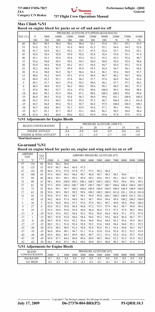
737 Flight Crew Operations Manual
Performance Inflight - QRHGeneral
737-800/CFM56-7B27JAACategory C/N Brakes
Copyright © The Boeing Company. See title page for details.
D6-27370-804-BRI(P2) PI-QRH.10.3
Max Climb %N1Based on engine bleed for packs on or off and anti-ice off
%N1 Adjustments for Engine Bleeds
Go-around %N1Based on engine bleed for packs on, engine and wing anti-ice on or off
%N1 Adjustments for Engine Bleeds
TAT (°C)PRESSURE ALTITUDE (FT)/SPEED (KIAS/MACH)
0 5000 10000 15000 20000 25000 30000 35000 37000 41000280 280 280 280 280 280 280 .78 .78 .78
60 90.2 90.5 90.4 90.6 90.4 92.1 93.8 95.1 95.2 93.555 91.0 91.2 91.3 91.4 90.8 91.5 93.1 94.4 94.5 92.850 91.7 92.0 92.1 92.2 91.7 91.5 92.4 93.7 93.8 92.145 92.4 92.6 92.8 93.0 92.6 92.4 92.4 93.0 93.1 91.440 93.1 93.3 93.6 93.8 93.4 93.2 93.2 92.3 92.4 90.735 93.6 94.0 94.3 94.5 94.3 94.0 94.0 93.0 92.4 90.830 92.9 94.8 95.0 95.2 95.1 94.8 94.7 93.9 93.3 91.825 92.2 94.8 95.7 95.9 95.9 95.5 95.4 94.7 94.1 92.820 91.4 94.0 96.5 96.7 96.6 96.2 96.1 95.4 94.9 93.715 90.6 93.2 95.9 97.5 97.4 96.9 96.7 96.2 95.7 94.610 89.9 92.5 95.1 97.8 98.3 97.7 97.4 96.9 96.5 95.65 89.1 91.7 94.3 97.0 99.2 98.6 98.1 97.7 97.3 96.50 88.3 90.9 93.5 96.2 98.6 99.6 99.1 98.5 98.2 97.5-5 87.6 90.1 92.7 95.4 97.8 99.6 100.0 99.2 99.0 98.4
-10 86.8 89.3 91.9 94.6 97.1 98.8 100.3 100.2 99.8 99.4-15 86.0 88.5 91.0 93.8 96.3 98.0 99.6 101.1 100.8 100.4-20 85.2 87.6 90.2 93.0 95.5 97.2 98.7 100.8 101.3 101.0-25 84.3 86.8 89.4 92.2 94.7 96.4 97.9 100.0 100.5 100.1-30 83.5 86.0 88.5 91.3 93.9 95.6 97.1 99.1 99.6 99.3-35 82.7 85.1 87.7 90.5 93.1 94.8 96.3 98.3 98.8 98.4-40 81.8 84.3 86.8 89.6 92.3 93.9 95.4 97.4 97.9 97.6
BLEED CONFIGURATION PRESSURE ALTITUDE (1000 FT)0 10 20 30 35 41
ENGINE ANTI-ICE -0.6 -0.8 -0.9 -0.9 -0.8 -0.8ENGINE & WING ANTI-ICE* -1.8 -2.1 -2.5 -2.7 -3.0 -3.0
*Dual bleed sources
AIRPORT OAT TAT
(°C)AIRPORT PRESSURE ALTITUDE (FT)
°C °F -2000 0 1000 2000 3000 4000 5000 6000 7000 8000 9000 1000057 134 60 95.0 96.2 96.852 125 55 95.9 96.7 96.6 96.8 97.547 116 50 96.6 97.6 97.8 97.8 97.7 97.5 98.2 98.842 108 45 97.4 98.4 98.5 98.6 98.7 98.8 98.7 98.5 98.5 99.037 99 40 98.0 99.1 99.2 99.3 99.4 99.5 99.6 99.5 99.1 98.9 98.8 99.132 90 35 98.1 99.9 100.0 100.1 100.1 100.3 100.3 100.2 99.9 99.6 99.6 99.527 81 30 97.3 99.8 100.4 100.7 100.7 100.7 100.7 100.7 100.6 100.4 100.4 100.322 72 25 96.6 99.1 99.7 100.2 100.6 100.9 100.9 100.9 100.9 100.9 100.9 100.817 63 20 95.8 98.3 98.9 99.5 99.8 100.2 100.5 100.9 101.0 101.1 101.0 101.012 54 15 95.0 97.5 98.1 98.7 99.1 99.4 99.8 100.1 100.5 100.9 101.3 101.27 45 10 94.2 96.8 97.4 98.0 98.3 98.7 99.0 99.4 99.8 100.2 100.5 100.92 36 5 93.4 96.0 96.6 97.2 97.6 97.9 98.3 98.7 99.0 99.4 99.8 100.2-3 27 0 92.6 95.2 95.8 96.4 96.8 97.2 97.5 97.9 98.3 98.7 99.0 99.4-8 18 -5 91.8 94.4 95.0 95.6 96.0 96.4 96.8 97.2 97.5 97.9 98.3 98.6
-13 9 -10 91.0 93.6 94.2 94.8 95.2 95.6 96.0 96.4 96.8 97.1 97.5 97.9-17 1 -15 90.2 92.8 93.4 94.0 94.4 94.8 95.2 95.6 96.0 96.4 96.7 97.1-22 -8 -20 89.3 92.0 92.6 93.2 93.6 94.0 94.4 94.8 95.2 95.6 95.9 96.3-27 -17 -25 88.5 91.1 91.8 92.4 92.8 93.2 93.6 94.0 94.4 94.8 95.1 95.5-32 -26 -30 87.6 90.3 90.9 91.6 92.0 92.4 92.8 93.3 93.6 94.0 94.3 94.7-37 -35 -35 86.8 89.4 90.1 90.7 91.1 91.6 92.0 92.4 92.8 93.2 93.5 93.9-42 -44 -40 85.9 88.6 89.2 89.9 90.3 90.7 91.2 91.6 92.0 92.4 92.7 93.0-47 -53 -45 85.0 87.7 88.4 89.0 89.4 89.9 90.3 90.8 91.2 91.5 91.9 92.2-52 -62 -50 84.1 86.8 87.5 88.2 88.6 89.0 89.5 90.0 90.3 90.7 91.0 91.4
BLEED CONFIGURATION
PRESSURE ALTITUDE (FT)-2000 0 1000 2000 3000 4000 5000 6000 7000 8000 9000 10000
PACKS OFF 0.7 0.8 0.8 0.8 0.8 0.9 0.9 0.9 0.9 0.9 0.9 0.9A/C HIGH -0.1 -0.1 -0.1 -0.1 -0.1 -0.1 -0.1 -0.1 -0.1 -0.1 -0.1 -0.1
July 17, 2009
General - Max Climb & Go Around %N1
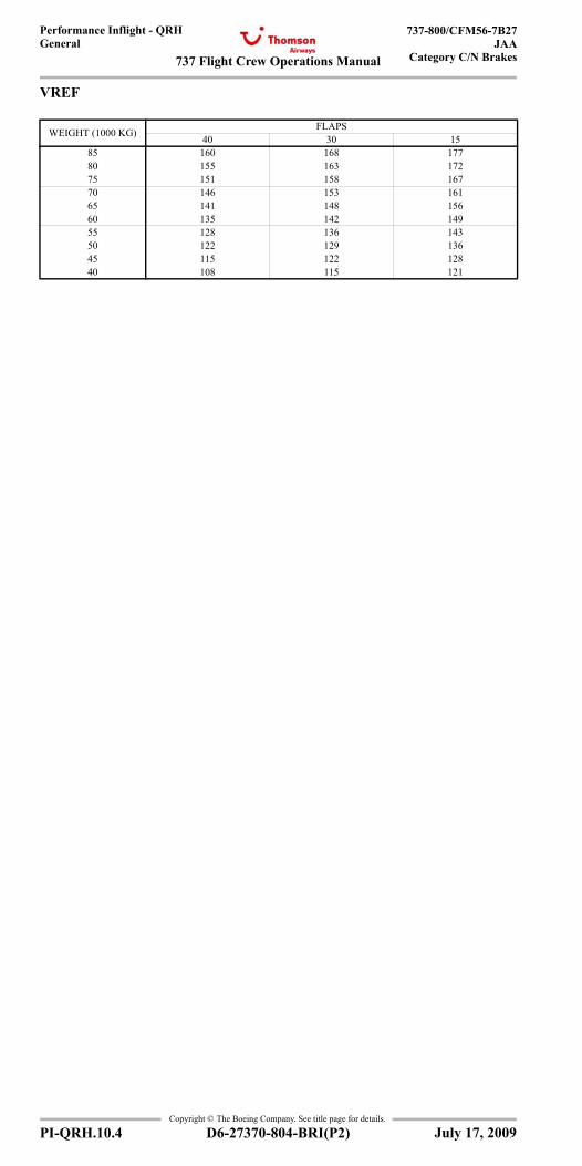
737 Flight Crew Operations Manual
Performance Inflight - QRHGeneral
737-800/CFM56-7B27JAA
Category C/N Brakes
Copyright © The Boeing Company. See title page for details.
PI-QRH.10.4 D6-27370-804-BRI(P2)
VREF
WEIGHT (1000 KG) FLAPS40 30 15
85 160 168 17780 155 163 17275 151 158 16770 146 153 16165 141 148 15660 135 142 14955 128 136 14350 122 129 13645 115 122 12840 108 115 121
July 17, 2009
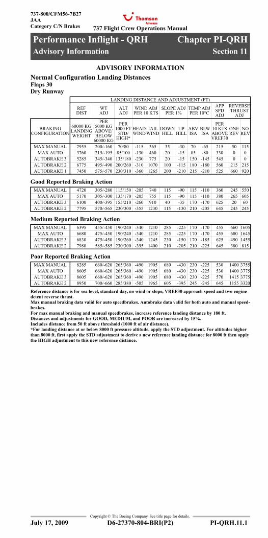
737 Flight Crew Operations Manual
Performance Inflight - QRH Chapter PI-QRHAdvisory Information Section 11
737-800/CFM56-7B27JAACategory C/N Brakes
Copyright © The Boeing Company. See title page for details.
D6-27370-804-BRI(P2) PI-QRH.11.1
PI-QRH.11 Performance Inflight - QRH-Advisory InformationADVISORY INFORMATIONAdvisory Information
Normal Configuration Landing DistancesFlaps 30Dry Runway
Good Reported Braking Action
Medium Reported Braking Action
Poor Reported Braking Action
Reference distance is for sea level, standard day, no wind or slope, VREF30 approach speed and two engine detent reverse thrust.Max manual braking data valid for auto speedbrakes. Autobrake data valid for both auto and manual speed-brakes.For max manual braking and manual speedbrakes, increase reference landing distance by 180 ft.Distances and adjustments for GOOD, MEDIUM, and POOR are increased by 15%.Includes distance from 50 ft above threshold (1000 ft of air distance).*For landing distance at or below 8000 ft pressure altitude, apply the STD adjustment. For altitudes higher than 8000 ft, first apply the STD adjustment to derive a new reference landing distance for 8000 ft then apply the HIGH adjustment to this new reference distance.
LANDING DISTANCE AND ADJUSTMENT (FT)
REF DIST
WT ADJ
ALT ADJ
WIND ADJ PER 10 KTS
SLOPE ADJ PER 1%
TEMP ADJ PER 10°C
APP SPD ADJ
REVERSE THRUST
ADJ
BRAKING CONFIGURATION
60000 KG LANDING WEIGHT
PER 5000 KG ABOVE/BELOW
60000 KG
PER 1000 FT
STD/HIGH*
HEAD WIND
TAIL WIND
DOWNHILL
UP HILL
ABV ISA
BLW ISA
PER 10 KTS ABOVE VREF30
ONE REV
NO REV
MAX MANUAL 2955 200/-160 70/80 -115 365 35 -30 70 -65 215 50 115MAX AUTO 3760 215/-195 85/100 -130 460 20 -15 85 -80 330 0 0
AUTOBRAKE 3 5285 345/-340 135/180 -230 775 20 -15 150 -145 545 0 0AUTOBRAKE 2 6775 495/-490 200/260 -310 1070 100 -115 180 -180 560 215 215AUTOBRAKE 1 7450 575/-570 230/310 -360 1265 200 -210 215 -210 525 660 920
MAX MANUAL 4720 305/-280 115/150 -205 740 115 -90 115 -110 360 245 550MAX AUTO 5170 305/-300 135/170 -205 755 115 -90 115 -110 380 265 605
AUTOBRAKE 3 6100 400/-395 155/210 -260 910 40 -35 170 -170 625 20 60AUTOBRAKE 2 7795 570/-565 230/300 -355 1230 115 -130 210 -205 645 245 245
MAX MANUAL 6395 455/-450 190/240 -340 1210 285 -225 170 -170 455 660 1605MAX AUTO 6680 475/-450 190/240 -340 1210 285 -225 170 -170 455 680 1645
AUTOBRAKE 3 6830 475/-450 190/260 -340 1245 230 -150 170 -185 625 490 1455AUTOBRAKE 2 7980 585/-585 230/300 -395 1400 210 -205 210 -225 645 380 815
MAX MANUAL 8285 660/-620 265/360 -490 1905 680 -430 230 -225 530 1400 3755MAX AUTO 8605 660/-620 265/360 -490 1905 680 -430 230 -225 530 1400 3775
AUTOBRAKE 3 8605 660/-620 265/360 -490 1905 680 -430 230 -225 570 1415 3775AUTOBRAKE 2 8950 700/-660 285/380 -505 1965 605 -395 245 -245 645 1155 3320
July 17, 2009
Advisory Information
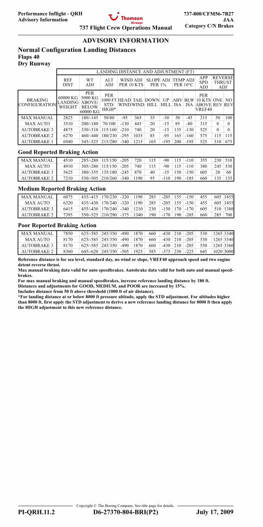
737 Flight Crew Operations Manual
Performance Inflight - QRHAdvisory Information
737-800/CFM56-7B27JAA
Category C/N Brakes
Copyright © The Boeing Company. See title page for details.
PI-QRH.11.2 D6-27370-804-BRI(P2)
ADVISORY INFORMATIONAdvisory Information
Normal Configuration Landing DistancesFlaps 40Dry Runway
Good Reported Braking Action
Medium Reported Braking Action
Poor Reported Braking Action
Reference distance is for sea level, standard day, no wind or slope, VREF40 approach speed and two engine detent reverse thrust.Max manual braking data valid for auto speedbrakes. Autobrake data valid for both auto and manual speed-brakes.For max manual braking and manual speedbrakes, increase reference landing distance by 180 ft.Distances and adjustments for GOOD, MEDIUM, and POOR are increased by 15%.Includes distance from 50 ft above threshold (1000 ft of air distance).*For landing distance at or below 8000 ft pressure altitude, apply the STD adjustment. For altitudes higher than 8000 ft, first apply the STD adjustment to derive a new reference landing distance for 8000 ft then apply the HIGH adjustment to this new reference distance.
LANDING DISTANCE AND ADJUSTMENT (FT)
REF DIST
WT ADJ
ALT ADJ
WIND ADJ PER 10 KTS
SLOPE ADJ PER 1%
TEMP ADJ PER 10°C
APP SPD ADJ
REVERSE THRUST
ADJ
BRAKING CONFIGURATION
60000 KG LANDING WEIGHT
PER 5000 KG ABOVE/BELOW
60000 KG
PER 1000 FT
STD/HIGH*
HEAD WIND
TAIL WIND
DOWNHILL
UP HILL
ABV ISA
BLW ISA
PER 10 KTS ABOVE VREF40
ONE REV
NO REV
MAX MANUAL 2825 180/-145 50/80 -95 365 35 -30 50 -45 215 50 100MAX AUTO 3510 200/-180 70/100 -130 445 20 -15 85 -80 315 0 0
AUTOBRAKE 3 4875 330/-310 115/160 -210 740 20 -15 135 -130 525 0 0AUTOBRAKE 2 6270 460/-440 180/230 -295 1035 85 -95 165 -160 575 115 115AUTOBRAKE 1 6940 545/-525 215/280 -340 1215 165 -195 200 -195 525 510 675
MAX MANUAL 4510 285/-280 115/150 -205 720 115 -90 115 -110 355 230 510MAX AUTO 4910 305/-280 115/150 -205 740 115 -90 115 -110 380 245 530
AUTOBRAKE 3 5625 380/-355 135/180 -245 870 40 -35 150 -150 605 20 60AUTOBRAKE 2 7210 530/-505 210/260 -340 1190 95 -110 190 -185 660 135 135
MAX MANUAL 6075 435/-415 170/230 -320 1190 285 -205 155 -150 455 605 1455MAX AUTO 6320 435/-430 170/240 -320 1190 285 -205 155 -150 455 605 1455
AUTOBRAKE 3 6415 455/-430 170/240 -340 1210 230 -150 170 -170 605 510 1380AUTOBRAKE 2 7395 550/-525 210/290 -375 1340 190 -170 190 -205 660 285 700
MAX MANUAL 7850 625/-585 245/350 -490 1870 660 -430 210 -205 530 1265 3340MAX AUTO 8170 625/-585 245/350 -490 1870 660 -430 210 -205 530 1265 3340
AUTOBRAKE 3 8170 625/-585 245/350 -490 1870 660 -430 210 -205 550 1265 3360AUTOBRAKE 2 8360 645/-620 245/350 -505 1925 585 -375 230 -225 645 1020 3000
July 17, 2009
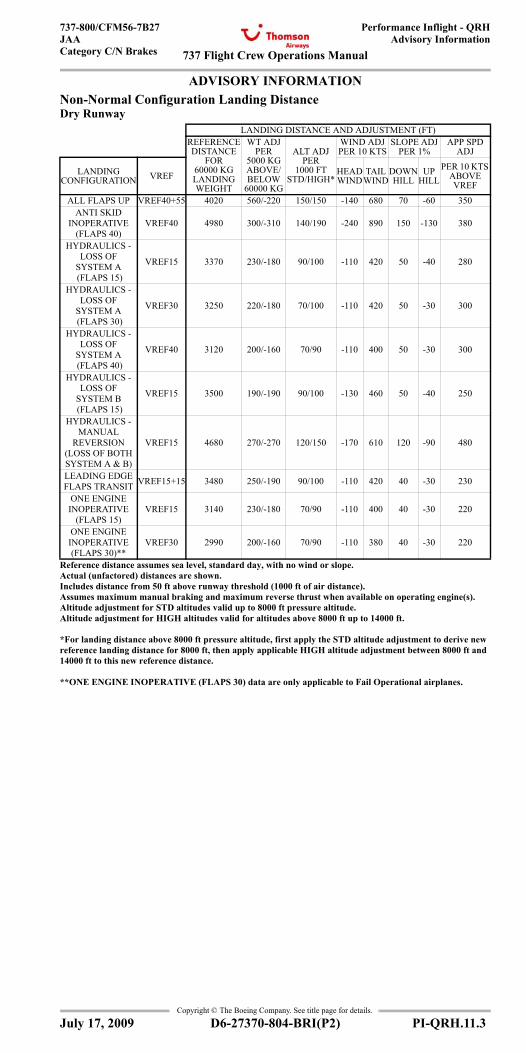
737 Flight Crew Operations Manual
Performance Inflight - QRHAdvisory Information
737-800/CFM56-7B27JAACategory C/N Brakes
Copyright © The Boeing Company. See title page for details.
D6-27370-804-BRI(P2) PI-QRH.11.3
ADVISORY INFORMATIONAdvisory Information
Non-Normal Configuration Landing DistanceDry Runway
LANDING DISTANCE AND ADJUSTMENT (FT)REFERENCE DISTANCE
FOR 60000 KG LANDING WEIGHT
WT ADJ PER
5000 KG ABOVE/BELOW
60000 KG
ALT ADJ PER
1000 FT STD/HIGH*
WIND ADJ PER 10 KTS
SLOPE ADJ PER 1%
APP SPD ADJ
LANDING CONFIGURATION VREF HEAD
WINDTAIL
WINDDOWN HILL
UP HILL
PER 10 KTS ABOVE VREF
ALL FLAPS UP VREF40+55 4020 560/-220 150/150 -140 680 70 -60 350ANTI SKID
INOPERATIVE (FLAPS 40)
VREF40 4980 300/-310 140/190 -240 890 150 -130 380
HYDRAULICS - LOSS OF
SYSTEM A (FLAPS 15)
VREF15 3370 230/-180 90/100 -110 420 50 -40 280
HYDRAULICS - LOSS OF
SYSTEM A (FLAPS 30)
VREF30 3250 220/-180 70/100 -110 420 50 -30 300
HYDRAULICS - LOSS OF
SYSTEM A (FLAPS 40)
VREF40 3120 200/-160 70/90 -110 400 50 -30 300
HYDRAULICS - LOSS OF
SYSTEM B (FLAPS 15)
VREF15 3500 190/-190 90/100 -130 460 50 -40 250
HYDRAULICS - MANUAL
REVERSION (LOSS OF BOTH SYSTEM A & B)
VREF15 4680 270/-270 120/150 -170 610 120 -90 480
LEADING EDGE FLAPS TRANSIT VREF15+15 3480 250/-190 90/100 -110 420 40 -30 230
ONE ENGINE INOPERATIVE
(FLAPS 15)VREF15 3140 230/-180 70/90 -110 400 40 -30 220
ONE ENGINE INOPERATIVE (FLAPS 30)**
VREF30 2990 200/-160 70/90 -110 380 40 -30 220
Reference distance assumes sea level, standard day, with no wind or slope.Actual (unfactored) distances are shown.Includes distance from 50 ft above runway threshold (1000 ft of air distance).Assumes maximum manual braking and maximum reverse thrust when available on operating engine(s).Altitude adjustment for STD altitudes valid up to 8000 ft pressure altitude.Altitude adjustment for HIGH altitudes valid for altitudes above 8000 ft up to 14000 ft.
*For landing distance above 8000 ft pressure altitude, first apply the STD altitude adjustment to derive new reference landing distance for 8000 ft, then apply applicable HIGH altitude adjustment between 8000 ft and 14000 ft to this new reference distance.
**ONE ENGINE INOPERATIVE (FLAPS 30) data are only applicable to Fail Operational airplanes.
July 17, 2009

737 Flight Crew Operations Manual
Performance Inflight - QRHAdvisory Information
737-800/CFM56-7B27JAA
Category C/N Brakes
Copyright © The Boeing Company. See title page for details.
PI-QRH.11.4 D6-27370-804-BRI(P2)
ADVISORY INFORMATIONAdvisory Information
Non-Normal Configuration Landing DistanceDry Runway
LANDING DISTANCE AND ADJUSTMENT (FT)REFERENCE DISTANCE
FOR 60000 KG LANDING WEIGHT
WT ADJ PER
5000 KG ABOVE/BELOW
60000 KG
ALT ADJ PER
1000 FT STD/HIGH*
WIND ADJ PER 10 KTS
SLOPE ADJ PER 1%
APP SPD ADJ
LANDING CONFIGURATION VREF HEAD
WINDTAIL
WINDDOWN HILL
UP HILL
PER 10 KTS ABOVE VREF
STABILIZER TRIM
INOPERATIVEVREF15 3110 230/-180 70/90 -110 400 40 -30 220
JAMMED ORRESTRICTED
FLIGHTCONTROLS
VREF15 3110 230/-180 70/90 -110 400 40 -30 220
TRAILING EDGE FLAP
ASYMMETRY (30 ≤ FLAPS < 40)
VREF30 2960 200/-160 70/90 -110 370 40 -30 220
TRAILING EDGE FLAP
ASYMMETRY (15 ≤ FLAPS < 30)
VREF15 3110 230/-180 70/90 -110 400 40 -30 220
TRAILING EDGE FLAP
ASYMMETRY (1 ≤ FLAPS < 15)
VREF40+30 3450 280/-190 90/100 -110 430 40 -30 230
TRAILING EDGE FLAP
DISAGREE (30 ≤ FLAPS < 40)
VREF30 2960 200/-160 70/90 -110 370 40 -30 220
TRAILING EDGE FLAP
DISAGREE (15 ≤ FLAPS < 30)
VREF15 3110 230/-180 70/90 -110 400 40 -30 220
TRAILING EDGE FLAP
DISAGREE (1 ≤ FLAPS < 15)
VREF40+30 3450 280/-190 90/100 -110 430 40 -30 230
TRAILING EDGE FLAPS UP VREF40+40 3650 370/-210 100/100 -130 550 50 -30 230
Reference distance assumes sea level, standard day, with no wind or slope.Actual (unfactored) distances are shown.Includes distance from 50 ft above runway threshold (1000 ft of air distance).Assumes maximum manual braking and maximum reverse thrust when available on operating engine(s).Altitude adjustment for STD altitudes valid up to 8000 ft pressure altitude.Altitude adjustment for HIGH altitudes valid for altitudes above 8000 ft up to 14000 ft.
*For landing distance above 8000 ft pressure altitude, first apply the STD altitude adjustment to derive new reference landing distance for 8000 ft, then apply applicable HIGH altitude adjustment between 8000 ft and 14000 ft to this new reference distance.
July 17, 2009

737 Flight Crew Operations Manual
Performance Inflight - QRHAdvisory Information
737-800/CFM56-7B27JAACategory C/N Brakes
Copyright © The Boeing Company. See title page for details.
D6-27370-804-BRI(P2) PI-QRH.11.5
ADVISORY INFORMATIONAdvisory Information
Non-Normal Configuration Landing DistanceGood Reported Braking Action
LANDING DISTANCE AND ADJUSTMENT (FT)REFERENCE DISTANCE
FOR 60000 KG LANDING WEIGHT
WT ADJ PER
5000 KG ABOVE/BELOW
60000 KG
ALT ADJ PER
1000 FT STD/HIGH*
WIND ADJ PER 10 KTS
SLOPE ADJ PER 1%
APP SPD ADJ
LANDING CONFIGURATION VREF HEAD
WINDTAIL
WINDDOWN HILL
UP HILL
PER 10 KTS ABOVE VREF
ALL FLAPS UP VREF40+55 5450 300/-310 150/200 -210 740 120 -90 280ANTI SKID
INOPERATIVE (FLAPS 40)
VREF40 5530 370/-360 150/200 -270 1090 220 -180 420
HYDRAULICS - LOSS OF
SYSTEM A (FLAPS 15)
VREF15 4880 320/-320 140/190 -190 740 140 -110 430
HYDRAULICS - LOSS OF
SYSTEM A (FLAPS 30)
VREF30 4630 300/-290 140/170 -190 730 140 -110 430
HYDRAULICS - LOSS OF
SYSTEM A (FLAPS 40)
VREF40 4400 280/-270 120/170 -190 710 140 -110 430
HYDRAULICS - LOSS OF
SYSTEM B (FLAPS 15)
VREF15 4430 280/-270 120/150 -190 680 100 -80 330
HYDRAULICS - MANUAL
REVERSION (LOSS OF BOTH SYSTEM A & B)
VREF15 5780 350/-360 150/200 -240 830 190 -160 560
LEADING EDGE FLAPS TRANSIT VREF15+15 4840 300/-290 140/190 -190 710 120 -90 320
ONE ENGINE INOPERATIVE
(FLAPS 15)VREF15 4430 270/-270 120/150 -190 690 120 -90 330
ONE ENGINE INOPERATIVE (FLAPS 30)**
VREF30 4220 250/-260 100/150 -180 680 100 -95 330
Reference distance assumes sea level, standard day, with no wind or slope.Actual (unfactored) distances are shown.Includes distance from 50 ft above runway threshold (1000 ft of air distance).Assumes maximum manual braking and maximum reverse thrust when available on operating engine(s).Altitude adjustment for STD altitudes valid up to 8000 ft pressure altitude.Altitude adjustment for HIGH altitudes valid for altitudes above 8000 ft up to 14000 ft.
*For landing distance above 8000 ft pressure altitude, first apply the STD altitude adjustment to derive new reference landing distance for 8000 ft, then apply applicable HIGH altitude adjustment between 8000 ft and 14000 ft to this new reference distance.
**ONE ENGINE INOPERATIVE (FLAPS 30) data are only applicable to Fail Operational airplanes.
July 17, 2009

737 Flight Crew Operations Manual
Performance Inflight - QRHAdvisory Information
737-800/CFM56-7B27JAA
Category C/N Brakes
Copyright © The Boeing Company. See title page for details.
PI-QRH.11.6 D6-27370-804-BRI(P2)
ADVISORY INFORMATIONAdvisory Information
Non-Normal Configuration Landing DistanceGood Reported Braking Action
LANDING DISTANCE AND ADJUSTMENT (FT)REFERENCE DISTANCE
FOR 60000 KG LANDING WEIGHT
WT ADJ PER
5000 KG ABOVE/BELOW
60000 KG
ALT ADJ PER
1000 FT STD/HIGH*
WIND ADJ PER 10 KTS
SLOPE ADJ PER 1%
APP SPD ADJ
LANDING CONFIGURATION VREF HEAD
WINDTAIL
WINDDOWN HILL
UP HILL
PER 10 KTS ABOVE VREF
STABILIZER TRIM
INOPERATIVEVREF15 4250 270/-260 120/150 -180 660 100 -80 300
JAMMED OR RESTRICTED
FLIGHTCONTROLS
VREF15 4250 270/-260 120/150 -180 660 100 -80 300
TRAILING EDGE FLAP
ASYMMETRY (30 ≤ FLAPS < 40)
VREF30 4110 270/-240 100/140 -180 640 100 -80 320
TRAILING EDGE FLAP
ASYMMETRY (15 ≤ FLAPS < 30)
VREF15 4250 270/-260 120/150 -180 660 100 -80 300
TRAILING EDGE FLAP
ASYMMETRY (1 ≤ FLAPS < 15)
VREF40+30 4710 270/-270 140/170 -190 690 100 -80 300
TRAILING EDGE FLAP
DISAGREE (30 ≤ FLAPS < 40)
VREF30 4110 270/-240 100/140 -180 640 100 -80 320
TRAILING EDGE FLAP
DISAGREE (15 ≤ FLAPS < 30)
VREF15 4250 270/-260 120/150 -180 660 100 -80 300
TRAILING EDGE FLAP
DISAGREE (1 ≤ FLAPS < 15)
VREF40+30 4710 270/-270 140/170 -190 690 100 -80 300
TRAILING EDGE FLAPS UP VREF40+40 4960 270/-270 140/190 -190 710 100 -90 280
Reference distance assumes sea level, standard day, with no wind or slope.Actual (unfactored) distances are shown.Includes distance from 50 ft above runway threshold (1000 ft of air distance).Assumes maximum manual braking and maximum reverse thrust when available on operating engine(s).Altitude adjustment for STD altitudes valid up to 8000 ft pressure altitude.Altitude adjustment for HIGH altitudes valid for altitudes above 8000 ft up to 14000 ft.
*For landing distance above 8000 ft pressure altitude, first apply the STD altitude adjustment to derive new reference landing distance for 8000 ft, then apply applicable HIGH altitude adjustment between 8000 ft and 14000 ft to this new reference distance.
July 17, 2009

737 Flight Crew Operations Manual
Performance Inflight - QRHAdvisory Information
737-800/CFM56-7B27JAACategory C/N Brakes
Copyright © The Boeing Company. See title page for details.
D6-27370-804-BRI(P2) PI-QRH.11.7
ADVISORY INFORMATIONAdvisory Information
Non-Normal Configuration Landing DistanceMedium Reported Braking Action
LANDING DISTANCE AND ADJUSTMENT (FT)REFERENCE DISTANCE
FOR 60000 KG LANDING WEIGHT
WT ADJ PER
5000 KG ABOVE/BELOW
60000 KG
ALT ADJ PER
1000 FT STD/HIGH*
WIND ADJ PER 10 KTS
SLOPE ADJ PER 1%
APP SPD ADJ
LANDING CONFIGURATION VREF HEAD
WINDTAIL
WINDDOWN HILL
UP HILL
PER 10 KTS ABOVE VREF
ALL FLAPS UP VREF40+55 7680 500/-500 250/330 -320 1240 280 -240 400ANTI SKID
INOPERATIVE (FLAPS 40)
VREF40 6990 510/-500 220/300 -420 1690 500 -340 480
HYDRAULICS - LOSS OF
SYSTEM A (FLAPS 15)
VREF15 6670 510/-490 220/300 -320 1200 320 -260 550
HYDRAULICS - LOSS OF
SYSTEM A (FLAPS 30)
VREF30 6260 460/-450 200/270 -310 1170 300 -240 530
HYDRAULICS - LOSS OF
SYSTEM A (FLAPS 40)
VREF40 5890 430/-420 190/250 -310 1140 280 -220 530
HYDRAULICS - LOSS OF
SYSTEM B (FLAPS 15)
VREF15 6060 450/-420 190/250 -290 1120 270 -210 430
HYDRAULICS - MANUAL
REVERSION (LOSS OF BOTH SYSTEM A & B)
VREF15 7960 560/-550 230/330 -370 1300 400 -340 690
LEADING EDGE FLAPS TRANSIT VREF15+15 6630 460/-450 200/280 -310 1170 270 -220 420
ONE ENGINE INOPERATIVE
(FLAPS 15)VREF15 6340 450/-450 190/250 -320 1190 300 -240 450
ONE ENGINE INOPERATIVE (FLAPS 30)**
VREF30 5930 420/-420 170/230 -310 1150 280 -220 450
Reference distance assumes sea level, standard day, with no wind or slope.Actual (unfactored) distances are shown.Includes distance from 50 ft above runway threshold (1000 ft of air distance).Assumes maximum manual braking and maximum reverse thrust when available on operating engine(s).Altitude adjustment for STD altitudes valid up to 8000 ft pressure altitude.Altitude adjustment for HIGH altitudes valid for altitudes above 8000 ft up to 14000 ft.
*For landing distance above 8000 ft pressure altitude, first apply the STD altitude adjustment to derive new reference landing distance for 8000 ft, then apply applicable HIGH altitude adjustment between 8000 ft and 14000 ft to this new reference distance.
**ONE ENGINE INOPERATIVE (FLAPS 30) data are only applicable to Fail Operational airplanes.
July 17, 2009
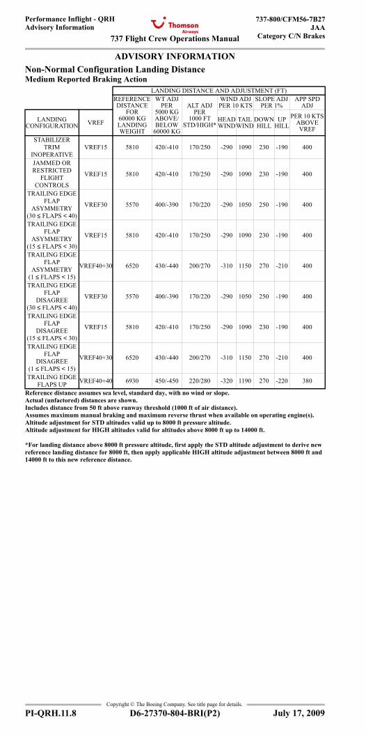
737 Flight Crew Operations Manual
Performance Inflight - QRHAdvisory Information
737-800/CFM56-7B27JAA
Category C/N Brakes
Copyright © The Boeing Company. See title page for details.
PI-QRH.11.8 D6-27370-804-BRI(P2)
ADVISORY INFORMATIONAdvisory Information
Non-Normal Configuration Landing DistanceMedium Reported Braking Action
LANDING DISTANCE AND ADJUSTMENT (FT)REFERENCE DISTANCE
FOR 60000 KG LANDING WEIGHT
WT ADJ PER
5000 KG ABOVE/BELOW
60000 KG
ALT ADJ PER
1000 FT STD/HIGH*
WIND ADJ PER 10 KTS
SLOPE ADJ PER 1%
APP SPD ADJ
LANDING CONFIGURATION VREF HEAD
WINDTAIL
WINDDOWN HILL
UP HILL
PER 10 KTS ABOVE VREF
STABILIZER TRIM
INOPERATIVEVREF15 5810 420/-410 170/250 -290 1090 230 -190 400
JAMMED ORRESTRICTED
FLIGHTCONTROLS
VREF15 5810 420/-410 170/250 -290 1090 230 -190 400
TRAILING EDGE FLAP
ASYMMETRY (30 ≤ FLAPS < 40)
VREF30 5570 400/-390 170/220 -290 1050 250 -190 400
TRAILING EDGE FLAP
ASYMMETRY (15 ≤ FLAPS < 30)
VREF15 5810 420/-410 170/250 -290 1090 230 -190 400
TRAILING EDGE FLAP
ASYMMETRY (1 ≤ FLAPS < 15)
VREF40+30 6520 430/-440 200/270 -310 1150 270 -210 400
TRAILING EDGE FLAP
DISAGREE (30 ≤ FLAPS < 40)
VREF30 5570 400/-390 170/220 -290 1050 250 -190 400
TRAILING EDGE FLAP
DISAGREE (15 ≤ FLAPS < 30)
VREF15 5810 420/-410 170/250 -290 1090 230 -190 400
TRAILING EDGE FLAP
DISAGREE (1 ≤ FLAPS < 15)
VREF40+30 6520 430/-440 200/270 -310 1150 270 -210 400
TRAILING EDGE FLAPS UP VREF40+40 6930 450/-450 220/280 -320 1190 270 -220 380
Reference distance assumes sea level, standard day, with no wind or slope.Actual (unfactored) distances are shown.Includes distance from 50 ft above runway threshold (1000 ft of air distance).Assumes maximum manual braking and maximum reverse thrust when available on operating engine(s).Altitude adjustment for STD altitudes valid up to 8000 ft pressure altitude.Altitude adjustment for HIGH altitudes valid for altitudes above 8000 ft up to 14000 ft.
*For landing distance above 8000 ft pressure altitude, first apply the STD altitude adjustment to derive new reference landing distance for 8000 ft, then apply applicable HIGH altitude adjustment between 8000 ft and 14000 ft to this new reference distance.
July 17, 2009
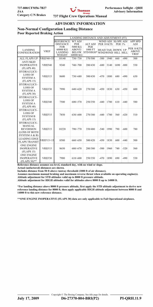
737 Flight Crew Operations Manual
Performance Inflight - QRHAdvisory Information
737-800/CFM56-7B27JAACategory C/N Brakes
Copyright © The Boeing Company. See title page for details.
D6-27370-804-BRI(P2) PI-QRH.11.9
ADVISORY INFORMATIONAdvisory Information
Non-Normal Configuration Landing DistancePoor Reported Braking Action
LANDING DISTANCE AND ADJUSTMENT (FT)REFERENCE DISTANCE
FOR 60000 KG LANDING WEIGHT
WT ADJ PER
5000 KG ABOVE/BELOW
60000 KG
ALT ADJ PER
1000 FT STD/HIGH*
WIND ADJ PER 10 KTS
SLOPE ADJ PER 1%
APP SPD ADJ
LANDING CONFIGURATION VREF HEAD
WINDTAIL
WINDDOWN HILL
UP HILL
PER 10 KTS ABOVE VREF
ALL FLAPS UP VREF40+55 10140 730/-730 370/500 -500 1940 660 -490 500ANTI SKID
INOPERATIVE (FLAPS 40)
VREF40 9240 740/-700 280/430 -680 3140 1690 -800 530
HYDRAULICS - LOSS OF
SYSTEM A (FLAPS 15)
VREF15 8600 730/-680 300/430 -470 1880 680 -490 630
HYDRAULICS - LOSS OF
SYSTEM A (FLAPS 30)
VREF30 7990 640/-620 270/380 -450 1830 630 -450 600
HYDRAULICS - LOSS OF
SYSTEM A (FLAPS 40)
VREF40 7500 600/-570 250/350 -440 1780 610 -440 580
HYDRAULICS - LOSS OF
SYSTEM B (FLAPS 15)
VREF15 7850 630/-600 270/380 -440 1780 560 -420 510
HYDRAULICS - MANUAL
REVERSION (LOSS OF BOTH SYSTEM A & B)
VREF15 10220 790/-770 350/480 -540 1990 790 -600 780
LEADING EDGE FLAPS TRANSIT VREF15+15 8580 660/-650 300/420 -450 1830 600 -440 500
ONE ENGINE INOPERATIVE
(FLAPS 15)VREF15 8650 680/-670 280/380 -500 1960 740 -520 560
ONE ENGINE INOPERATIVE (FLAPS 30)**
VREF30 7980 610/-600 250/350 -470 1890 690 -490 530
Reference distance assumes sea level, standard day, with no wind or slope.Actual (unfactored) distances are shown.Includes distance from 50 ft above runway threshold (1000 ft of air distance).Assumes maximum manual braking and maximum reverse thrust when available on operating engine(s).Altitude adjustment for STD altitudes valid up to 8000 ft pressure altitude.Altitude adjustment for HIGH altitudes valid for altitudes above 8000 ft up to 14000 ft.
*For landing distance above 8000 ft pressure altitude, first apply the STD altitude adjustment to derive new reference landing distance for 8000 ft, then apply applicable HIGH altitude adjustment between 8000 ft and 14000 ft to this new reference distance.
**ONE ENGINE INOPERATIVE (FLAPS 30) data are only applicable to Fail Operational airplanes.
July 17, 2009
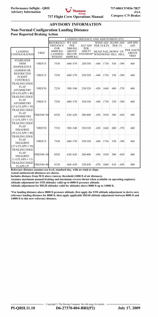
737 Flight Crew Operations Manual
Performance Inflight - QRHAdvisory Information
737-800/CFM56-7B27JAA
Category C/N Brakes
Copyright © The Boeing Company. See title page for details.
PI-QRH.11.10 D6-27370-804-BRI(P2)
ADVISORY INFORMATIONAdvisory Information
Non-Normal Configuration Landing DistancePoor Reported Braking Action
LANDING DISTANCE AND ADJUSTMENT (FT)REFERENCE DISTANCE
FOR 60000 KG LANDING WEIGHT
WT ADJ PER
5000 KG ABOVE/BELOW
60000 KG
ALT ADJ PER
1000 FT STD/HIGH*
WIND ADJ PER 10 KTS
SLOPE ADJ PER 1%
APP SPD ADJ
LANDING CONFIGURATION VREF HEAD
WINDTAIL
WINDDOWN HILL
UP HILL
PER 10 KTS ABOVE VREF
STABILIZER TRIM
INOPERATIVEVREF15 7530 600/-570 250/350 -440 1730 530 -390 460
JAMMED OR RESTRICTED
FLIGHTCONTROLS
VREF15 7530 600/-570 250/350 -440 1730 530 -390 460
TRAILING EDGE FLAP
ASYMMETRY (30 ≤ FLAPS < 40)
VREF30 7210 580/-540 230/320 -420 1660 600 -370 460
TRAILING EDGE FLAP
ASYMMETRY (15 ≤ FLAPS < 30)
VREF15 7530 600/-570 250/350 -440 1730 530 -390 460
TRAILING EDGE FLAP
ASYMMETRY (1 ≤ FLAPS < 15)
VREF40+30 8520 630/-620 280/400 -450 1830 580 -420 480
TRAILING EDGE FLAP
DISAGREE (30 ≤ FLAPS < 40)
VREF30 7210 580/-540 230/320 -420 1660 600 -370 460
TRAILING EDGE FLAP
DISAGREE (15 ≤ FLAPS < 30)
VREF15 7530 600/-570 250/350 -440 1730 530 -390 460
TRAILING EDGE FLAP
DISAGREE (1 ≤ FLAPS < 15)
VREF40+30 8520 630/-620 280/400 -450 1830 580 -420 480
TRAILING EDGE FLAPS UP VREF40+40 9130 660/-650 320/430 -470 1860 610 -450 480
Reference distance assumes sea level, standard day, with no wind or slope.Actual (unfactored) distances are shown.Includes distance from 50 ft above runway threshold (1000 ft of air distance).Assumes maximum manual braking and maximum reverse thrust when available on operating engine(s).Altitude adjustment for STD altitudes valid up to 8000 ft pressure altitude.Altitude adjustment for HIGH altitudes valid for altitudes above 8000 ft up to 14000 ft.
*For landing distance above 8000 ft pressure altitude, first apply the STD altitude adjustment to derive new reference landing distance for 8000 ft, then apply applicable HIGH altitude adjustment between 8000 ft and 14000 ft to this new reference distance.
July 17, 2009
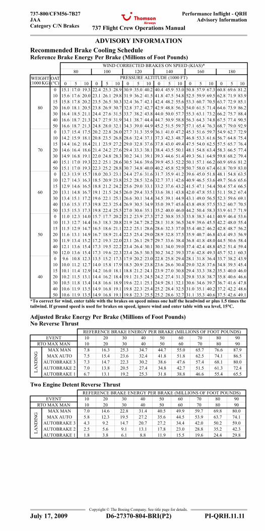
737 Flight Crew Operations Manual
Performance Inflight - QRHAdvisory Information
737-800/CFM56-7B27JAACategory C/N Brakes
Copyright © The Boeing Company. See title page for details.
D6-27370-804-BRI(P2) PI-QRH.11.11
ADVISORY INFORMATIONRecommended Brake Cooling Schedule Reference Brake Energy Per Brake (Millions of Foot Pounds)
Adjusted Brake Energy Per Brake (Millions of Foot Pounds)No Reverse Thrust
Two Engine Detent Reverse Thrust
WIND CORRECTED BRAKES ON SPEED (KIAS)*80 100 120 140 160 180
WEIGHT (1000 KG)
OAT (°C)
PRESSURE ALTITUDE (1000 FT)0 5 10 0 5 10 0 5 10 0 5 10 0 5 10 0 5 10
80
0 15.1 17.0 19.3 22.4 25.3 28.9 30.9 35.0 40.2 40.4 45.9 53.0 50.8 57.9 67.3 60.8 69.6 81.210 15.6 17.6 20.0 23.1 26.1 29.8 31.9 36.2 41.5 41.8 47.5 54.8 52.5 59.9 69.5 62.8 71.9 83.915 15.8 17.8 20.2 23.5 26.5 30.3 32.4 36.7 42.1 42.4 48.2 55.6 53.3 60.7 70.5 63.7 72.9 85.120 16.0 18.1 20.5 23.8 26.9 30.7 32.8 37.2 42.7 42.9 48.8 56.3 54.0 61.5 71.4 64.6 73.9 86.230 16.4 18.5 21.1 24.4 27.6 31.5 33.7 38.2 43.8 44.0 50.0 57.7 55.3 63.1 73.2 66.2 75.7 88.440 16.6 18.7 21.3 24.7 27.9 31.9 34.1 38.7 44.4 44.7 50.9 58.8 56.3 64.3 74.8 67.5 77.4 90.550 16.6 18.7 21.3 24.8 28.0 32.1 34.3 39.0 44.9 45.2 51.5 59.7 57.1 65.4 76.3 68.7 79.0 92.9
70
0 13.7 15.4 17.5 20.2 22.8 26.0 27.7 31.3 35.9 36.1 41.0 47.2 45.3 51.6 59.7 54.9 62.7 72.910 14.2 15.9 18.1 20.8 23.5 26.8 28.6 32.4 37.1 37.3 42.3 48.7 46.8 53.3 61.6 56.7 64.8 75.415 14.4 16.2 18.4 21.1 23.9 27.2 29.0 32.8 37.6 37.8 43.0 49.4 47.5 54.0 62.5 57.5 65.7 76.420 14.6 16.4 18.6 21.4 24.2 27.6 29.4 33.3 38.1 38.4 43.5 50.1 48.1 54.8 63.4 58.3 66.5 77.430 14.9 16.8 19.1 22.0 24.8 28.3 30.2 34.1 39.1 39.3 44.6 51.4 49.3 56.1 64.9 59.8 68.2 79.440 15.1 17.0 19.3 22.2 25.1 28.6 30.5 34.6 39.6 39.9 45.3 52.2 50.1 57.1 66.2 60.9 69.6 81.250 15.1 17.0 19.3 22.3 25.2 28.8 30.7 34.8 40.0 40.2 45.8 52.9 50.7 58.0 67.4 61.8 70.9 83.0
60
0 12.3 13.9 15.7 18.0 20.3 23.1 24.4 27.6 31.6 31.7 35.9 41.2 39.6 45.0 51.8 48.1 54.8 63.510 12.7 14.3 16.3 18.5 20.9 23.8 25.2 28.5 32.6 32.7 37.1 42.6 40.9 46.5 53.6 49.7 56.6 65.615 12.9 14.6 16.5 18.8 21.2 24.2 25.6 29.0 33.1 33.2 37.6 43.2 41.5 47.1 54.4 50.4 57.4 66.520 13.1 14.8 16.7 19.1 21.5 24.5 26.0 29.4 33.5 33.6 38.1 43.8 42.0 47.8 55.1 51.1 58.2 67.430 13.4 15.1 17.2 19.6 22.1 25.1 26.6 30.1 34.4 34.5 39.1 44.9 43.1 49.0 56.5 52.3 59.6 69.140 13.6 15.3 17.3 19.8 22.3 25.4 26.9 30.5 34.9 35.0 39.7 45.6 43.8 49.8 57.5 53.2 60.7 70.550 13.5 15.3 17.3 19.8 22.4 25.5 27.0 30.6 35.1 35.2 40.0 46.0 44.2 50.4 58.3 53.9 61.7 71.9
50
0 11.0 12.3 14.0 15.7 17.7 20.2 21.2 23.9 27.3 27.2 30.8 35.3 33.8 38.3 44.1 40.9 46.4 53.610 11.3 12.7 14.4 16.3 18.3 20.8 21.9 24.7 28.2 28.1 31.8 36.5 34.9 39.6 45.5 42.2 48.0 55.415 11.5 12.9 14.7 16.5 18.6 21.1 22.2 25.1 28.6 28.6 32.3 37.0 35.4 40.2 46.2 42.8 48.7 56.220 11.6 13.1 14.9 16.7 18.9 21.4 22.5 25.4 29.0 28.9 32.8 37.5 35.9 40.7 46.8 43.4 49.3 56.930 11.9 13.4 15.2 17.2 19.3 22.0 23.1 26.1 29.7 29.7 33.6 38.4 36.8 41.8 48.0 44.5 50.6 58.440 12.1 13.6 15.4 17.3 19.5 22.2 23.4 26.4 30.1 30.1 34.0 39.0 37.4 42.4 48.8 45.2 51.4 59.450 12.0 13.6 15.4 17.3 19.6 22.3 23.4 26.5 30.3 30.2 34.2 39.3 37.6 42.8 49.3 45.7 52.1 60.3
40
0 9.6 10.8 12.3 13.5 15.2 17.3 17.9 20.2 23.0 22.8 25.8 29.4 28.1 31.8 36.4 33.7 38.2 43.910 10.0 11.2 12.7 14.0 15.8 17.9 18.5 20.9 23.8 23.6 26.6 30.4 29.0 32.8 37.6 34.8 39.5 45.415 10.1 11.4 12.9 14.2 16.0 18.1 18.8 21.2 24.1 23.9 27.0 30.8 29.4 33.3 38.2 35.3 40.0 46.020 10.2 11.5 13.1 14.4 16.2 18.4 19.1 21.5 24.5 24.2 27.4 31.3 29.8 33.8 38.7 35.8 40.6 46.630 10.5 11.8 13.4 14.8 16.6 18.9 19.6 22.1 25.1 24.9 28.1 32.1 30.6 34.6 39.7 36.7 41.6 47.840 10.6 11.9 13.5 14.9 16.8 19.1 19.8 22.3 25.4 25.2 28.4 32.5 31.0 35.1 40.2 37.2 42.2 48.650 10.6 11.9 13.5 14.9 16.8 19.1 19.8 22.3 25.5 25.2 28.6 32.7 31.1 35.3 40.6 37.5 42.6 49.1
*To correct for wind, enter table with the brakes on speed minus one half the headwind or plus 1.5 times the tailwind. If ground speed is used for brakes on speed, ignore wind and enter table with sea level, 15°C.
REFERENCE BRAKE ENERGY PER BRAKE (MILLIONS OF FOOT POUNDS)EVENT 10 20 30 40 50 60 70 80 90
RTO MAX MAN 10 20 30 40 50 60 70 80 90
LAN
DIN
G
MAX MAN 7.8 16.3 25.3 34.7 44.7 55.0 65.7 76.6 87.9MAX AUTO 7.5 15.4 23.6 32.4 41.8 51.8 62.5 74.1 86.5
AUTOBRAKE 3 7.3 14.7 22.3 30.2 38.6 47.6 57.4 68.1 80.0AUTOBRAKE 2 7.0 13.8 20.5 27.4 34.8 42.7 51.5 61.3 72.4AUTOBRAKE 1 6.7 13.1 19.2 25.3 31.8 38.8 46.6 55.4 65.5
REFERENCE BRAKE ENERGY PER BRAKE (MILLIONS OF FOOT POUNDS)EVENT 10 20 30 40 50 60 70 80 90
RTO MAX MAN 10 20 30 40 50 60 70 80 90
LAN
DIN
G
MAX MAN 7.0 14.6 22.8 31.4 40.5 49.9 59.7 69.8 80.0MAX AUTO 5.8 12.3 19.5 27.2 35.6 44.5 53.9 63.7 74.1
AUTOBRAKE 3 4.3 9.2 14.7 20.7 27.2 34.4 42.0 50.2 59.0AUTOBRAKE 2 2.5 5.6 9.1 13.1 17.8 23.0 28.8 35.2 42.3AUTOBRAKE 1 1.8 3.8 6.1 8.8 11.9 15.5 19.6 24.4 29.8
July 17, 2009
Advisory Information
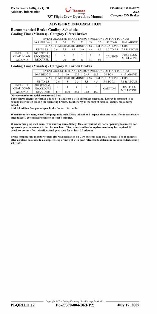
737 Flight Crew Operations Manual
Performance Inflight - QRHAdvisory Information
737-800/CFM56-7B27JAA
Category C/N Brakes
Copyright © The Boeing Company. See title page for details.
PI-QRH.11.12 D6-27370-804-BRI(P2)
ADVISORY INFORMATIONRecommended Brake Cooling Schedule Cooling Time (Minutes) - Category C Steel Brakes
Cooling Time (Minutes) - Category N Carbon Brakes
EVENT ADJUSTED BRAKE ENERGY (MILLIONS OF FOOT POUNDS)16 & BELOW 17 20 23 25 28 32 33 TO 48 49 & ABOVE
BRAKE TEMPERATURE MONITOR SYSTEM INDICATION ON CDSUP TO 2.4 2.6 3.1 3.5 3.9 4.4 4.9 5.0 TO 7.5 7.5 & ABOVE
INFLIGHT GEAR DOWN
NO SPECIAL PROCEDURE REQUIRED
1 2 3 4 5 6 CAUTION FUSE PLUG MELT ZONEGROUND 10 20 30 40 50 60
EVENT ADJUSTED BRAKE ENERGY (MILLIONS OF FOOT POUNDS)16 & BELOW 17 19 20.9 23.5 26.9 30 TO 41 41 & ABOVE
BRAKE TEMPERATURE MONITOR SYSTEM INDICATION ON CDSUP TO 2.5 2.6 3 3.3 3.8 4.5 5.0 TO 7.1 7.1 & ABOVE
INFLIGHT GEAR DOWN
NO SPECIAL PROCEDURE REQUIRED
1 4 5 6 7 CAUTION FUSE PLUG MELT ZONEGROUND 6.7 16.0 24.1 34.2 45.9
Observe maximum quick turnaround limit.Table shows energy per brake added by a single stop with all brakes operating. Energy is assumed to be equally distributed among the operating brakes. Total energy is the sum of residual energy plus energy added. Add 1.0 million foot pounds per brake for each taxi mile.
When in caution zone, wheel fuse plugs may melt. Delay takeoff and inspect after one hour. If overheat occurs after takeoff, extend gear soon for at least 7 minutes.
When in fuse plug melt zone, clear runway immediately. Unless required, do not set parking brake. Do not approach gear or attempt to taxi for one hour. Tire, wheel and brake replacement may be required. If overheat occurs after takeoff, extend gear soon for at least 12 minutes.
Brake temperature monitor system (BTMS) indication on CDS systems page may be used 10 to 15 minutes after airplane has come to a complete stop or inflight with gear retracted to determine recommended cooling schedule.
July 17, 2009
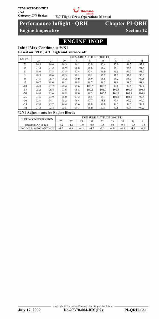
737 Flight Crew Operations Manual
Performance Inflight - QRH Chapter PI-QRHEngine Inoperative Section 12
737-800/CFM56-7B27JAACategory C/N Brakes
Copyright © The Boeing Company. See title page for details.
D6-27370-804-BRI(P2) PI-QRH.12.1
PI-QRH.12 Performance Inflight - QRH-Engine InoperativeENGINE INOPEngine Inoperative
Initial Max Continuous %N1Based on .79M, A/C high and anti-ice off
%N1 Adjustments for Engine Bleeds
TAT (°C) PRESSURE ALTITUDE (1000 FT)25 27 29 31 33 35 37 39 41
20 96.8 96.6 96.3 96.1 95.9 95.4 95.0 94.7 93.915 97.4 97.2 96.9 96.8 96.6 96.2 95.7 95.5 94.810 98.0 97.8 97.5 97.4 97.4 96.9 96.5 96.3 95.75 98.3 98.6 98.3 98.1 98.1 97.7 97.3 97.1 96.60 97.5 98.7 99.2 99.0 98.9 98.5 98.2 98.0 97.5-5 96.7 98.0 99.1 99.8 99.7 99.3 98.9 98.7 98.4
-10 96.0 97.2 98.4 99.6 100.5 100.2 99.8 99.6 99.4-15 95.2 96.4 97.6 98.8 100.1 101.0 100.8 100.6 100.3-20 94.4 95.6 96.8 98.0 99.3 100.5 101.1 100.8 100.6-25 93.6 94.9 96.0 97.2 98.5 99.7 100.2 100.0 99.8-30 92.8 94.1 95.2 96.4 97.7 98.8 99.4 99.2 99.0-35 92.0 93.2 94.4 95.6 96.8 98.0 98.5 98.3 98.1-40 91.2 92.4 93.5 94.7 96.0 97.1 97.6 97.4 97.2
BLEED CONFIGURATION PRESSURE ALTITUDE (1000 FT)25 27 29 31 33 35 37 39 41
ENGINE ANTI-ICE -1.2 -1.1 -1.0 -0.9 -0.8 -0.8 -0.8 -0.8 -0.8ENGINE & WING ANTI-ICE -4.2 -4.4 -4.5 -4.7 -5.0 -4.8 -4.8 -4.8 -4.8
July 17, 2009
Engine Inoperative
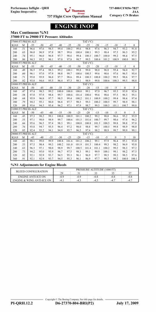
737 Flight Crew Operations Manual
Performance Inflight - QRHEngine Inoperative
737-800/CFM56-7B27JAA
Category C/N Brakes
Copyright © The Boeing Company. See title page for details.
PI-QRH.12.2 D6-27370-804-BRI(P2)
ENGINE INOPEngine Inoperative
Max Continuous %N137000 FT to 29000 FT Pressure Altitudes
%N1 Adjustments for Engine Bleeds
37000 FT PRESS ALT TAT (°C)KIAS M -55 -50 -45 -40 -35 -30 -25 -20 -15 -10 -5 0160 .51 96.6 97.6 98.5 99.4 100.2 99.6 98.8 97.6 96.3 94.7 93.2 91.8200 .63 96.0 96.9 97.8 98.7 99.6 100.4 100.1 99.3 98.4 97.5 96.3 95.2240 .74 95.1 96.0 96.8 97.7 98.6 99.4 100.3 100.7 100.0 99.2 98.4 97.5280 .86 94.3 95.2 96.1 97.0 97.8 98.7 99.5 100.4 101.2 100.9 100.0 99.1
35000 FT PRESS ALT TAT (°C)KIAS M -55 -50 -45 -40 -35 -30 -25 -20 -15 -10 -5 0160 .49 96.5 97.4 98.3 99.2 100.1 99.8 99.0 98.0 96.8 95.4 94.0 92.7200 .60 96.1 97.0 97.9 98.8 99.7 100.6 100.5 99.6 98.6 97.6 96.5 95.4240 .71 95.0 95.9 96.8 97.7 98.6 99.4 100.3 100.8 100.2 99.5 98.6 97.7280 .82 93.8 94.6 95.5 96.4 97.3 98.1 98.9 99.8 100.6 100.3 99.5 98.8
33000 FT PRESS ALT TAT (°C)KIAS M -50 -45 -40 -35 -30 -25 -20 -15 -10 -5 0 5160 .47 97.4 98.3 99.2 100.0 100.8 100.0 99.1 97.9 96.7 95.3 93.9 92.6200 .58 97.0 97.9 98.8 99.7 100.6 101.4 100.6 99.6 98.6 97.5 96.3 95.1240 .68 95.9 96.8 97.7 98.5 99.4 100.2 101.1 100.9 100.2 99.4 98.4 97.4280 .79 94.3 95.1 96.0 96.8 97.7 98.5 99.3 100.2 100.5 99.7 98.9 98.1320 .89 93.6 94.5 95.4 96.2 97.1 97.9 98.7 99.5 100.3 101.1 100.7 99.8
31000 FT PRESS ALT TAT (°C)KIAS M -50 -45 -40 -35 -30 -25 -20 -15 -10 -5 0 5160 .45 97.3 98.2 99.1 100.0 100.9 101.1 100.2 99.2 98.0 96.6 95.2 93.9200 .55 97.1 98.0 98.9 99.7 100.6 101.5 101.6 100.7 99.7 98.6 97.4 96.2240 .66 95.6 96.5 97.4 98.3 99.1 100.0 100.8 101.3 100.5 99.8 98.8 97.8280 .76 93.8 94.7 95.5 96.4 97.2 98.0 98.8 99.7 100.5 99.8 98.9 98.0320 .85 92.4 93.2 94.1 94.9 95.7 96.5 97.4 98.2 98.9 99.7 99.9 99.1
29000 FT PRESS ALT TAT (°C)KIAS M -45 -40 -35 -30 -25 -20 -15 -10 -5 0 5 10160 .43 98.1 99.0 99.9 100.8 101.6 101.2 100.2 99.1 97.9 96.4 95.1 93.8200 .53 97.5 98.4 99.3 100.2 101.0 101.9 101.3 100.4 99.3 98.2 96.9 95.8240 .63 96.3 97.1 98.0 98.9 99.7 100.5 101.4 101.1 100.2 99.2 98.3 97.2280 .73 94.2 95.0 95.9 96.7 97.5 98.3 99.1 99.9 100.1 99.1 98.2 97.5320 .82 92.1 92.9 93.7 94.5 95.3 96.1 96.9 97.7 98.5 99.2 98.5 97.6360 .91 92.1 92.9 93.7 94.5 95.3 96.1 96.9 97.7 98.5 99.2 100.0 100.1
BLEED CONFIGURATION PRESSURE ALTITUDE (1000 FT)29 31 33 35 37
ENGINE ANTI-ICE ON -0.9 -0.9 -0.8 -0.8 -0.8ENGINE & WING ANTI-ICE ON -4.1 -4.3 -4.5 -4.7 -4.7
July 17, 2009
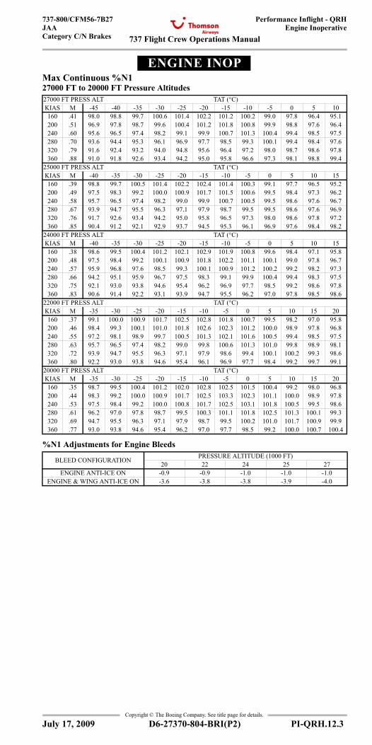
737 Flight Crew Operations Manual
Performance Inflight - QRHEngine Inoperative
737-800/CFM56-7B27JAACategory C/N Brakes
Copyright © The Boeing Company. See title page for details.
D6-27370-804-BRI(P2) PI-QRH.12.3
ENGINE INOPEngine Inoperative
Max Continuous %N127000 FT to 20000 FT Pressure Altitudes
%N1 Adjustments for Engine Bleeds
27000 FT PRESS ALT TAT (°C)KIAS M -45 -40 -35 -30 -25 -20 -15 -10 -5 0 5 10160 .41 98.0 98.8 99.7 100.6 101.4 102.2 101.2 100.2 99.0 97.8 96.4 95.1200 .51 96.9 97.8 98.7 99.6 100.4 101.2 101.8 100.8 99.9 98.8 97.6 96.4240 .60 95.6 96.5 97.4 98.2 99.1 99.9 100.7 101.3 100.4 99.4 98.5 97.5280 .70 93.6 94.4 95.3 96.1 96.9 97.7 98.5 99.3 100.1 99.4 98.4 97.6320 .79 91.6 92.4 93.2 94.0 94.8 95.6 96.4 97.2 98.0 98.7 98.6 97.8360 .88 91.0 91.8 92.6 93.4 94.2 95.0 95.8 96.6 97.3 98.1 98.8 99.4
25000 FT PRESS ALT TAT (°C)KIAS M -40 -35 -30 -25 -20 -15 -10 -5 0 5 10 15160 .39 98.8 99.7 100.5 101.4 102.2 102.4 101.4 100.3 99.1 97.7 96.5 95.2200 .49 97.5 98.3 99.2 100.0 100.9 101.7 101.5 100.6 99.5 98.4 97.3 96.2240 .58 95.7 96.5 97.4 98.2 99.0 99.9 100.7 100.5 99.5 98.6 97.6 96.7280 .67 93.9 94.7 95.5 96.3 97.1 97.9 98.7 99.5 99.5 98.6 97.6 96.9320 .76 91.7 92.6 93.4 94.2 95.0 95.8 96.5 97.3 98.0 98.6 97.8 97.2360 .85 90.4 91.2 92.1 92.9 93.7 94.5 95.3 96.1 96.9 97.6 98.4 98.2
24000 FT PRESS ALT TAT (°C)KIAS M -40 -35 -30 -25 -20 -15 -10 -5 0 5 10 15160 .38 98.6 99.5 100.4 101.2 102.1 102.9 101.9 100.8 99.6 98.4 97.1 95.8200 .48 97.5 98.4 99.2 100.1 100.9 101.8 102.2 101.1 100.1 99.0 97.8 96.7240 .57 95.9 96.8 97.6 98.5 99.3 100.1 100.9 101.2 100.2 99.2 98.2 97.3280 .66 94.2 95.1 95.9 96.7 97.5 98.3 99.1 99.9 100.4 99.4 98.3 97.5320 .75 92.1 93.0 93.8 94.6 95.4 96.2 96.9 97.7 98.5 99.2 98.6 97.8360 .83 90.6 91.4 92.2 93.1 93.9 94.7 95.5 96.2 97.0 97.8 98.5 98.6
22000 FT PRESS ALT TAT (°C)KIAS M -35 -30 -25 -20 -15 -10 -5 0 5 10 15 20160 .37 99.1 100.0 100.9 101.7 102.5 102.8 101.8 100.7 99.5 98.2 97.0 95.8200 .46 98.4 99.3 100.1 101.0 101.8 102.6 102.3 101.2 100.0 98.9 97.8 96.8240 .55 97.2 98.1 98.9 99.7 100.5 101.3 102.1 101.6 100.5 99.4 98.5 97.5280 .63 95.7 96.5 97.4 98.2 99.0 99.8 100.6 101.3 101.0 99.8 98.9 98.1320 .72 93.9 94.7 95.5 96.3 97.1 97.9 98.6 99.4 100.1 100.2 99.3 98.6360 .80 92.2 93.0 93.8 94.6 95.4 96.1 96.9 97.7 98.4 99.2 99.7 99.1
20000 FT PRESS ALT TAT (°C)KIAS M -35 -30 -25 -20 -15 -10 -5 0 5 10 15 20160 .35 98.7 99.5 100.4 101.2 102.0 102.8 102.5 101.5 100.4 99.2 98.0 96.8200 .44 98.3 99.2 100.0 100.9 101.7 102.5 103.3 102.3 101.1 100.0 98.9 97.8240 .53 97.5 98.4 99.2 100.0 100.8 101.7 102.5 103.1 101.8 100.5 99.5 98.6280 .61 96.2 97.0 97.8 98.7 99.5 100.3 101.1 101.8 102.5 101.3 100.1 99.3320 .69 94.7 95.5 96.3 97.1 97.9 98.7 99.5 100.2 101.0 101.7 100.9 99.9360 .77 93.0 93.8 94.6 95.4 96.2 97.0 97.7 98.5 99.2 100.0 100.7 100.4
BLEED CONFIGURATION PRESSURE ALTITUDE (1000 FT)20 22 24 25 27
ENGINE ANTI-ICE ON -0.9 -0.9 -1.0 -1.0 -1.0ENGINE & WING ANTI-ICE ON -3.6 -3.8 -3.8 -3.9 -4.0
July 17, 2009
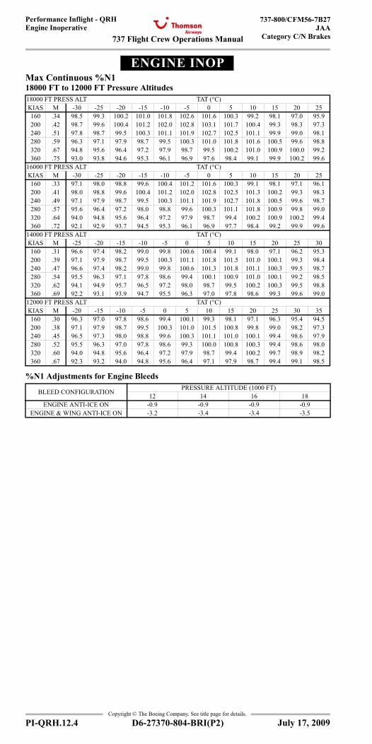
737 Flight Crew Operations Manual
Performance Inflight - QRHEngine Inoperative
737-800/CFM56-7B27JAA
Category C/N Brakes
Copyright © The Boeing Company. See title page for details.
PI-QRH.12.4 D6-27370-804-BRI(P2)
ENGINE INOPEngine Inoperative
Max Continuous %N118000 FT to 12000 FT Pressure Altitudes
%N1 Adjustments for Engine Bleeds
18000 FT PRESS ALT TAT (°C)KIAS M -30 -25 -20 -15 -10 -5 0 5 10 15 20 25160 .34 98.5 99.3 100.2 101.0 101.8 102.6 101.6 100.3 99.2 98.1 97.0 95.9200 .42 98.7 99.6 100.4 101.2 102.0 102.8 103.1 101.7 100.4 99.3 98.3 97.3240 .51 97.8 98.7 99.5 100.3 101.1 101.9 102.7 102.5 101.1 99.9 99.0 98.1280 .59 96.3 97.1 97.9 98.7 99.5 100.3 101.0 101.8 101.6 100.5 99.6 98.8320 .67 94.8 95.6 96.4 97.2 97.9 98.7 99.5 100.2 101.0 100.9 100.0 99.2360 .75 93.0 93.8 94.6 95.3 96.1 96.9 97.6 98.4 99.1 99.9 100.2 99.6
16000 FT PRESS ALT TAT (°C)KIAS M -30 -25 -20 -15 -10 -5 0 5 10 15 20 25160 .33 97.1 98.0 98.8 99.6 100.4 101.2 101.6 100.3 99.1 98.1 97.1 96.1200 .41 98.0 98.8 99.6 100.4 101.2 102.0 102.8 102.5 101.3 100.2 99.3 98.3240 .49 97.1 97.9 98.7 99.5 100.3 101.1 101.9 102.7 101.8 100.5 99.6 98.7280 .57 95.6 96.4 97.2 98.0 98.8 99.6 100.3 101.1 101.8 100.9 99.8 99.0320 .64 94.0 94.8 95.6 96.4 97.2 97.9 98.7 99.4 100.2 100.9 100.2 99.4360 .72 92.1 92.9 93.7 94.5 95.3 96.1 96.9 97.7 98.4 99.2 99.9 99.6
14000 FT PRESS ALT TAT (°C)KIAS M -25 -20 -15 -10 -5 0 5 10 15 20 25 30160 .31 96.6 97.4 98.2 99.0 99.8 100.6 100.4 99.1 98.0 97.1 96.2 95.3200 .39 97.1 97.9 98.7 99.5 100.3 101.1 101.8 101.5 101.0 100.1 99.3 98.4240 .47 96.6 97.4 98.2 99.0 99.8 100.6 101.3 101.8 101.1 100.3 99.5 98.7280 .54 95.5 96.3 97.1 97.8 98.6 99.4 100.1 100.9 101.0 100.1 99.2 98.5320 .62 94.1 94.9 95.7 96.5 97.2 98.0 98.7 99.5 100.2 100.3 99.5 98.8360 .69 92.2 93.1 93.9 94.7 95.5 96.3 97.0 97.8 98.6 99.3 99.6 99.0
12000 FT PRESS ALT TAT (°C)KIAS M -20 -15 -10 -5 0 5 10 15 20 25 30 35160 .30 96.3 97.0 97.8 98.6 99.4 100.1 99.3 98.1 97.1 96.3 95.4 94.5200 .38 97.1 97.9 98.7 99.5 100.3 101.0 101.5 100.8 99.8 99.0 98.2 97.3240 .45 96.5 97.3 98.0 98.8 99.6 100.3 101.1 101.0 100.1 99.4 98.6 97.9280 .52 95.5 96.3 97.0 97.8 98.6 99.3 100.0 100.8 100.3 99.4 98.6 98.0320 .60 94.0 94.8 95.6 96.4 97.2 97.9 98.7 99.4 100.2 99.7 98.9 98.2360 .67 92.3 93.2 94.0 94.8 95.6 96.4 97.1 97.9 98.7 99.4 99.1 98.5
BLEED CONFIGURATION PRESSURE ALTITUDE (1000 FT)12 14 16 18
ENGINE ANTI-ICE ON -0.9 -0.9 -0.9 -0.9ENGINE & WING ANTI-ICE ON -3.2 -3.4 -3.4 -3.5
July 17, 2009
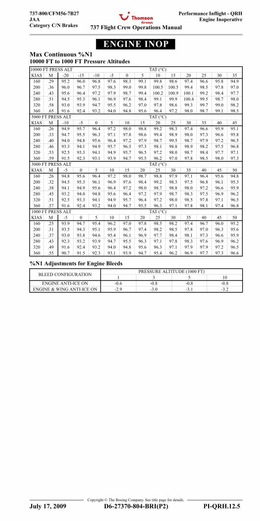
737 Flight Crew Operations Manual
Performance Inflight - QRHEngine Inoperative
737-800/CFM56-7B27JAACategory C/N Brakes
Copyright © The Boeing Company. See title page for details.
D6-27370-804-BRI(P2) PI-QRH.12.5
ENGINE INOPEngine Inoperative
Max Continuous %N110000 FT to 1000 FT Pressure Altitudes
%N1 Adjustments for Engine Bleeds
10000 FT PRESS ALT TAT (°C)KIAS M -20 -15 -10 -5 0 5 10 15 20 25 30 35160 .29 95.2 96.0 96.8 97.6 98.3 99.1 99.8 98.6 97.4 96.6 95.8 94.9200 .36 96.0 96.7 97.5 98.3 99.0 99.8 100.5 100.5 99.4 98.5 97.8 97.0240 .43 95.6 96.4 97.2 97.9 98.7 99.4 100.2 100.9 100.1 99.2 98.4 97.7280 .51 94.5 95.3 96.1 96.9 97.6 98.4 99.1 99.9 100.4 99.5 98.7 98.0320 .58 93.0 93.9 94.7 95.5 96.2 97.0 97.8 98.6 99.3 99.7 99.0 98.2360 .65 91.6 92.4 93.2 94.0 94.8 95.6 96.4 97.2 98.0 98.7 99.1 98.5
5000 FT PRESS ALT TAT (°C)KIAS M -10 -5 0 5 10 15 20 25 30 35 40 45160 .26 94.9 95.7 96.4 97.2 98.0 98.8 99.2 98.3 97.4 96.6 95.9 95.1200 .33 94.7 95.5 96.3 97.1 97.8 98.6 99.4 98.9 98.0 97.3 96.6 95.8240 .40 94.0 94.8 95.6 96.4 97.2 97.9 98.7 99.5 98.7 97.9 97.2 96.5280 .46 93.3 94.1 94.9 95.7 96.5 97.3 98.1 98.8 98.9 98.2 97.5 96.8320 .53 92.5 93.3 94.1 94.9 95.7 96.5 97.2 98.0 98.7 98.4 97.7 97.1360 .59 91.5 92.3 93.1 93.9 94.7 95.5 96.2 97.0 97.8 98.5 98.0 97.3
3000 FT PRESS ALT TAT (°C)KIAS M -5 0 5 10 15 20 25 30 35 40 45 50160 .26 94.8 95.6 96.4 97.2 98.0 98.7 98.8 97.9 97.1 96.4 95.6 94.8200 .32 94.5 95.3 96.1 96.9 97.6 98.4 99.2 98.3 97.5 96.8 96.1 95.3240 .38 94.1 94.9 95.6 96.4 97.2 98.0 98.7 98.8 98.0 97.2 96.6 95.9280 .45 93.2 94.0 94.8 95.6 96.4 97.2 97.9 98.7 98.3 97.5 96.9 96.2320 .51 92.5 93.3 94.1 94.9 95.7 96.4 97.2 98.0 98.5 97.8 97.1 96.5360 .57 91.6 92.4 93.2 94.0 94.7 95.5 96.3 97.1 97.8 98.1 97.4 96.8
1000 FT PRESS ALT TAT (°C)KIAS M -5 0 5 10 15 20 25 30 35 40 45 50160 .25 93.9 94.7 95.4 96.2 97.0 97.8 98.5 98.2 97.4 96.7 96.0 95.2200 .31 93.5 94.3 95.1 95.9 96.7 97.4 98.2 98.5 97.8 97.0 96.3 95.6240 .37 93.0 93.8 94.6 95.4 96.1 96.9 97.7 98.4 98.1 97.3 96.6 95.9280 .43 92.3 93.2 93.9 94.7 95.5 96.3 97.1 97.8 98.3 97.6 96.9 96.2320 .49 91.6 92.4 93.2 94.0 94.8 95.6 96.3 97.1 97.9 97.9 97.2 96.5360 .55 90.7 91.5 92.3 93.1 93.9 94.7 95.4 96.2 96.9 97.7 97.3 96.6
BLEED CONFIGURATION PRESSURE ALTITUDE (1000 FT)1 3 5 10
ENGINE ANTI-ICE ON -0.6 -0.8 -0.8 -0.8ENGINE & WING ANTI-ICE ON -2.9 -3.0 -3.1 -3.2
July 17, 2009
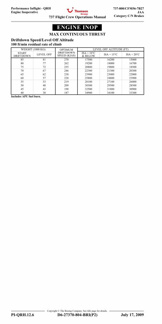
737 Flight Crew Operations Manual
Performance Inflight - QRHEngine Inoperative
737-800/CFM56-7B27JAA
Category C/N Brakes
Copyright © The Boeing Company. See title page for details.
PI-QRH.12.6 D6-27370-804-BRI(P2)
ENGINE INOPMAX CONTINUOUS THRUST
Driftdown Speed/Level Off Altitude100 ft/min residual rate of climb
WEIGHT (1000 KG) OPTIMUM DRIFTDOWN SPEED (KIAS)
LEVEL OFF ALTITUDE (FT)START
DRIFTDOWN LEVEL OFF ISA + 10°C & BELOW ISA + 15°C ISA + 20°C
85 81 270 17500 16200 1500080 77 262 19200 18000 1670075 72 255 20800 19800 1850070 67 246 22300 21300 2030065 62 238 23900 23000 2200060 57 228 25800 24800 2390055 53 219 28100 27100 2600050 48 209 30300 29500 2850045 43 198 32500 31800 3090040 38 187 34900 34100 33300
Includes APU fuel burn.
July 17, 2009
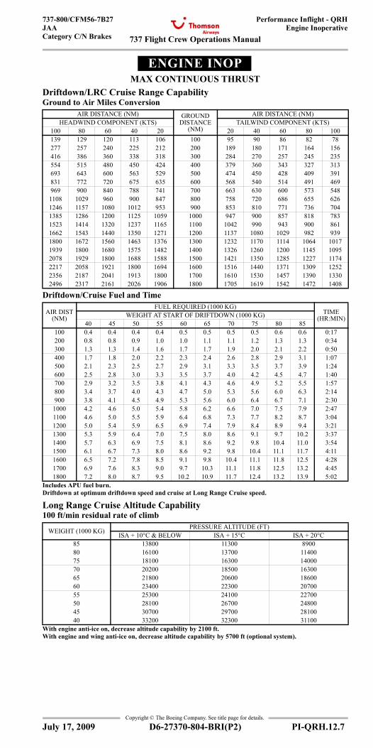
737 Flight Crew Operations Manual
Performance Inflight - QRHEngine Inoperative
737-800/CFM56-7B27JAACategory C/N Brakes
Copyright © The Boeing Company. See title page for details.
D6-27370-804-BRI(P2) PI-QRH.12.7
ENGINE INOPMAX CONTINUOUS THRUST
Driftdown/LRC Cruise Range CapabilityGround to Air Miles Conversion
Driftdown/Cruise Fuel and Time
Long Range Cruise Altitude Capability100 ft/min residual rate of climb
AIR DISTANCE (NM) GROUND DISTANCE
(NM)
AIR DISTANCE (NM)HEADWIND COMPONENT (KTS) TAILWIND COMPONENT (KTS)
100 80 60 40 20 20 40 60 80 100139 129 120 113 106 100 95 90 86 82 78277 257 240 225 212 200 189 180 171 164 156416 386 360 338 318 300 284 270 257 245 235554 515 480 450 424 400 379 360 343 327 313693 643 600 563 529 500 474 450 428 409 391831 772 720 675 635 600 568 540 514 491 469969 900 840 788 741 700 663 630 600 573 5481108 1029 960 900 847 800 758 720 686 655 6261246 1157 1080 1012 953 900 853 810 771 736 7041385 1286 1200 1125 1059 1000 947 900 857 818 7831523 1414 1320 1237 1165 1100 1042 990 943 900 8611662 1543 1440 1350 1271 1200 1137 1080 1029 982 9391800 1672 1560 1463 1376 1300 1232 1170 1114 1064 10171939 1800 1680 1575 1482 1400 1326 1260 1200 1145 10952078 1929 1800 1688 1588 1500 1421 1350 1285 1227 11742217 2058 1921 1800 1694 1600 1516 1440 1371 1309 12522356 2187 2041 1913 1800 1700 1610 1530 1457 1390 13302496 2317 2161 2026 1906 1800 1705 1619 1542 1472 1408
AIR DIST(NM)
FUEL REQUIRED (1000 KG)TIME
(HR:MIN)WEIGHT AT START OF DRIFTDOWN (1000 KG)40 45 50 55 60 65 70 75 80 85
100 0.4 0.4 0.4 0.4 0.5 0.5 0.5 0.5 0.6 0.6 0:17200 0.8 0.8 0.9 1.0 1.0 1.1 1.1 1.2 1.3 1.3 0:34300 1.3 1.3 1.4 1.6 1.7 1.7 1.9 2.0 2.1 2.2 0:50400 1.7 1.8 2.0 2.2 2.3 2.4 2.6 2.8 2.9 3.1 1:07500 2.1 2.3 2.5 2.7 2.9 3.1 3.3 3.5 3.7 3.9 1:24600 2.5 2.8 3.0 3.3 3.5 3.7 4.0 4.2 4.5 4.7 1:40700 2.9 3.2 3.5 3.8 4.1 4.3 4.6 4.9 5.2 5.5 1:57800 3.4 3.7 4.0 4.3 4.7 5.0 5.3 5.6 6.0 6.3 2:14900 3.8 4.1 4.5 4.9 5.3 5.6 6.0 6.4 6.7 7.1 2:30
1000 4.2 4.6 5.0 5.4 5.8 6.2 6.6 7.0 7.5 7.9 2:471100 4.6 5.0 5.5 5.9 6.4 6.8 7.3 7.7 8.2 8.7 3:041200 5.0 5.4 5.9 6.5 6.9 7.4 7.9 8.4 8.9 9.4 3:211300 5.3 5.9 6.4 7.0 7.5 8.0 8.6 9.1 9.7 10.2 3:371400 5.7 6.3 6.9 7.5 8.1 8.6 9.2 9.8 10.4 11.0 3:541500 6.1 6.7 7.3 8.0 8.6 9.2 9.8 10.4 11.1 11.7 4:111600 6.5 7.2 7.8 8.5 9.1 9.8 10.4 11.1 11.8 12.5 4:281700 6.9 7.6 8.3 9.0 9.7 10.3 11.1 11.8 12.5 13.2 4:451800 7.2 8.0 8.7 9.5 10.2 10.9 11.7 12.4 13.2 13.9 5:02
Includes APU fuel burn. Driftdown at optimum driftdown speed and cruise at Long Range Cruise speed.
WEIGHT (1000 KG) PRESSURE ALTITUDE (FT)ISA + 10°C & BELOW ISA + 15°C ISA + 20°C
85 13800 11300 890080 16100 13700 1140075 18100 16300 1400070 20200 18500 1630065 21800 20600 1860060 23400 22300 2070055 25300 24100 2270050 28100 26700 2480045 30700 29700 2810040 33200 32300 31100
With engine anti-ice on, decrease altitude capability by 2100 ft. With engine and wing anti-ice on, decrease altitude capability by 5700 ft (optional system).
July 17, 2009
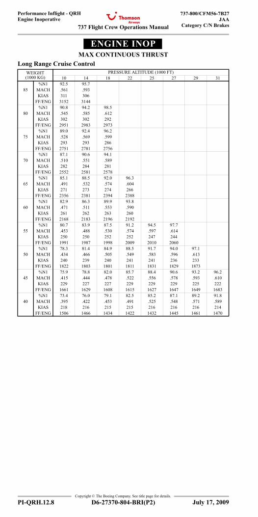
737 Flight Crew Operations Manual
Performance Inflight - QRHEngine Inoperative
737-800/CFM56-7B27JAA
Category C/N Brakes
Copyright © The Boeing Company. See title page for details.
PI-QRH.12.8 D6-27370-804-BRI(P2)
ENGINE INOPMAX CONTINUOUS THRUST
Long Range Cruise ControlWEIGHT(1000 KG)
PRESSURE ALTITUDE (1000 FT)10 14 18 22 25 27 29 31
%N1 92.5 95.785 MACH .561 .593
KIAS 311 306FF/ENG 3152 3144
%N1 90.8 94.2 98.580 MACH .545 .585 .612
KIAS 302 302 292FF/ENG 2951 2983 2973
%N1 89.0 92.4 96.275 MACH .528 .569 .599
KIAS 293 293 286FF/ENG 2751 2781 2756
%N1 87.1 90.6 94.170 MACH .510 .551 .589
KIAS 282 284 281FF/ENG 2552 2581 2578
%N1 85.1 88.5 92.0 96.365 MACH .491 .532 .574 .604
KIAS 271 273 274 266FF/ENG 2356 2381 2394 2388
%N1 82.9 86.3 89.9 93.860 MACH .471 .511 .553 .590
KIAS 261 262 263 260FF/ENG 2168 2183 2196 2192
%N1 80.7 83.9 87.5 91.2 94.5 97.755 MACH .453 .488 .530 .574 .597 .614
KIAS 250 250 252 252 247 244FF/ENG 1991 1987 1998 2009 2010 2060
%N1 78.3 81.4 84.9 88.5 91.7 94.0 97.150 MACH .434 .466 .505 .549 .583 .596 .613
KIAS 240 239 240 241 241 236 233FF/ENG 1822 1803 1801 1811 1831 1829 1873
%N1 75.9 78.8 82.0 85.7 88.4 90.6 93.2 96.245 MACH .415 .444 .478 .522 .556 .578 .593 .610
KIAS 229 227 227 229 229 229 225 222FF/ENG 1661 1629 1608 1615 1627 1647 1649 1683
%N1 73.4 76.0 79.1 82.5 85.2 87.1 89.2 91.840 MACH .395 .422 .453 .491 .525 .548 .571 .589
KIAS 218 216 215 215 216 216 216 214FF/ENG 1506 1466 1434 1422 1432 1445 1461 1470
July 17, 2009
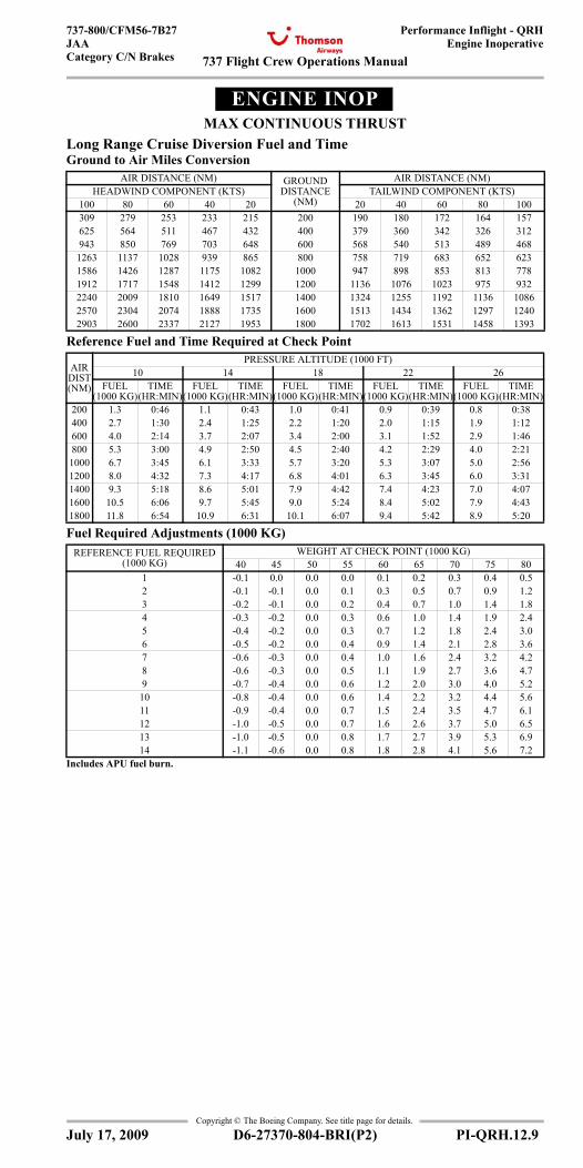
737 Flight Crew Operations Manual
Performance Inflight - QRHEngine Inoperative
737-800/CFM56-7B27JAACategory C/N Brakes
Copyright © The Boeing Company. See title page for details.
D6-27370-804-BRI(P2) PI-QRH.12.9
ENGINE INOPMAX CONTINUOUS THRUST
Long Range Cruise Diversion Fuel and TimeGround to Air Miles Conversion
Reference Fuel and Time Required at Check Point
Fuel Required Adjustments (1000 KG)
AIR DISTANCE (NM) GROUND DISTANCE
(NM)
AIR DISTANCE (NM)HEADWIND COMPONENT (KTS) TAILWIND COMPONENT (KTS)
100 80 60 40 20 20 40 60 80 100309 279 253 233 215 200 190 180 172 164 157625 564 511 467 432 400 379 360 342 326 312943 850 769 703 648 600 568 540 513 489 468
1263 1137 1028 939 865 800 758 719 683 652 6231586 1426 1287 1175 1082 1000 947 898 853 813 7781912 1717 1548 1412 1299 1200 1136 1076 1023 975 9322240 2009 1810 1649 1517 1400 1324 1255 1192 1136 10862570 2304 2074 1888 1735 1600 1513 1434 1362 1297 12402903 2600 2337 2127 1953 1800 1702 1613 1531 1458 1393
AIR DIST (NM)
PRESSURE ALTITUDE (1000 FT)10 14 18 22 26
FUEL (1000 KG)
TIME (HR:MIN)
FUEL (1000 KG)
TIME (HR:MIN)
FUEL (1000 KG)
TIME (HR:MIN)
FUEL (1000 KG)
TIME (HR:MIN)
FUEL (1000 KG)
TIME (HR:MIN)
200 1.3 0:46 1.1 0:43 1.0 0:41 0.9 0:39 0.8 0:38400 2.7 1:30 2.4 1:25 2.2 1:20 2.0 1:15 1.9 1:12600 4.0 2:14 3.7 2:07 3.4 2:00 3.1 1:52 2.9 1:46800 5.3 3:00 4.9 2:50 4.5 2:40 4.2 2:29 4.0 2:21
1000 6.7 3:45 6.1 3:33 5.7 3:20 5.3 3:07 5.0 2:561200 8.0 4:32 7.3 4:17 6.8 4:01 6.3 3:45 6.0 3:311400 9.3 5:18 8.6 5:01 7.9 4:42 7.4 4:23 7.0 4:071600 10.5 6:06 9.7 5:45 9.0 5:24 8.4 5:02 7.9 4:431800 11.8 6:54 10.9 6:31 10.1 6:07 9.4 5:42 8.9 5:20
REFERENCE FUEL REQUIRED (1000 KG)
WEIGHT AT CHECK POINT (1000 KG)40 45 50 55 60 65 70 75 80
1 -0.1 0.0 0.0 0.0 0.1 0.2 0.3 0.4 0.52 -0.1 -0.1 0.0 0.1 0.3 0.5 0.7 0.9 1.23 -0.2 -0.1 0.0 0.2 0.4 0.7 1.0 1.4 1.84 -0.3 -0.2 0.0 0.3 0.6 1.0 1.4 1.9 2.45 -0.4 -0.2 0.0 0.3 0.7 1.2 1.8 2.4 3.06 -0.5 -0.2 0.0 0.4 0.9 1.4 2.1 2.8 3.67 -0.6 -0.3 0.0 0.4 1.0 1.6 2.4 3.2 4.28 -0.6 -0.3 0.0 0.5 1.1 1.9 2.7 3.6 4.79 -0.7 -0.4 0.0 0.6 1.2 2.0 3.0 4.0 5.210 -0.8 -0.4 0.0 0.6 1.4 2.2 3.2 4.4 5.611 -0.9 -0.4 0.0 0.7 1.5 2.4 3.5 4.7 6.112 -1.0 -0.5 0.0 0.7 1.6 2.6 3.7 5.0 6.513 -1.0 -0.5 0.0 0.8 1.7 2.7 3.9 5.3 6.914 -1.1 -0.6 0.0 0.8 1.8 2.8 4.1 5.6 7.2
Includes APU fuel burn.
July 17, 2009
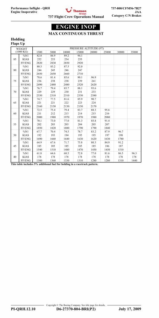
737 Flight Crew Operations Manual
Performance Inflight - QRHEngine Inoperative
737-800/CFM56-7B27JAA
Category C/N Brakes
Copyright © The Boeing Company. See title page for details.
PI-QRH.12.10 D6-27370-804-BRI(P2)
ENGINE INOPMAX CONTINUOUS THRUST
HoldingFlaps Up
WEIGHT (1000 KG)
PRESSURE ALTITUDE (FT)1500 5000 10000 15000 20000 25000 30000 35000
85%N1 82.0 84.9 89.2 94.1KIAS 252 253 254 255
FF/ENG 2820 2830 2850 2920
80%N1 80.3 83.2 87.5 92.0KIAS 244 245 246 247
FF/ENG 2650 2650 2660 2710
75%N1 78.6 81.4 85.6 90.1 96.9KIAS 236 238 238 239 241
FF/ENG 2490 2480 2480 2520 2620
70%N1 76.7 79.4 83.7 88.1 93.6KIAS 229 229 230 231 233
FF/ENG 2330 2310 2310 2330 2380
65%N1 74.7 77.5 81.6 85.9 90.7KIAS 221 221 222 223 224
FF/ENG 2160 2150 2130 2150 2170
60%N1 72.5 75.4 79.4 83.7 88.3 95.6KIAS 211 212 213 214 215 216
FF/ENG 2000 1980 1970 1970 1980 2080
55%N1 70.1 73.0 77.0 81.3 85.8 91.4KIAS 202 203 203 204 205 207
FF/ENG 1850 1820 1800 1790 1790 1840
50%N1 67.7 70.4 74.5 78.7 83.2 87.9 96.7KIAS 192 193 194 195 195 197 198
FF/ENG 1690 1660 1640 1630 1620 1630 1780
45%N1 64.9 67.6 71.7 75.8 80.3 84.9 91.2KIAS 185 185 185 185 185 186 187
FF/ENG 1540 1510 1480 1470 1450 1450 1510
40%N1 61.8 64.6 68.5 72.8 77.0 81.6 86.5 96.3KIAS 178 178 178 178 178 178 178 178
FF/ENG 1380 1360 1330 1310 1280 1280 1310 1440This table includes 5% additional fuel for holding in a racetrack pattern.
July 17, 2009
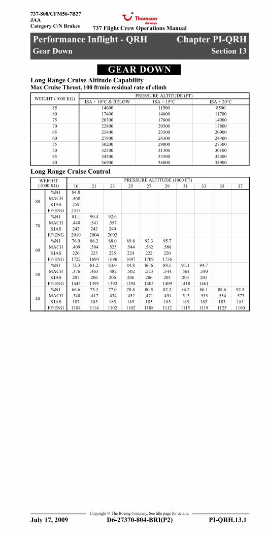
737 Flight Crew Operations Manual
Performance Inflight - QRH Chapter PI-QRHGear Down Section 13
737-800/CFM56-7B27JAACategory C/N Brakes
Copyright © The Boeing Company. See title page for details.
D6-27370-804-BRI(P2) PI-QRH.13.1
PI-QRH.13 Performance Inflight - QRH-Gear DownGEAR DOWNGear Down
Long Range Cruise Altitude CapabilityMax Cruise Thrust, 100 ft/min residual rate of climb
Long Range Cruise Control
WEIGHT (1000 KG) PRESSURE ALTITUDE (FT)ISA + 10°C & BELOW ISA + 15°C ISA + 20°C
85 14600 11500 850080 17400 14600 1170075 20300 17600 1490070 22800 20500 1780065 25400 23500 2090060 27800 26300 2440055 30200 29000 2730050 32300 31300 3010045 34500 33500 3240040 36900 36000 34900
WEIGHT (1000 KG)
PRESSURE ALTITUDE (1000 FT)10 21 23 25 27 29 31 33 35 37
80
%N1 84.8MACH .468KIAS 259
FF/ENG 2313
70
%N1 81.1 90.4 92.6MACH .440 .541 .557KIAS 243 242 240
FF/ENG 2010 2004 2002
60
%N1 76.9 86.2 88.0 89.8 92.3 95.7MACH .409 .504 .525 .544 .562 .580KIAS 226 225 225 224 222 220
FF/ENG 1722 1694 1696 1697 1709 1756
50
%N1 72.3 81.2 83.0 84.8 86.6 88.5 91.1 94.7MACH .376 .463 .482 .502 .523 .544 .561 .580KIAS 207 206 206 206 206 205 203 201
FF/ENG 1443 1395 1392 1394 1403 1409 1418 1461
40
%N1 66.6 75.3 77.0 78.8 80.5 82.3 84.2 86.1 88.6 92.5MACH .340 .417 .434 .452 .471 .491 .513 .535 .554 .573KIAS 187 185 185 185 185 185 185 185 183 181
FF/ENG 1184 1114 1102 1102 1108 1112 1115 1119 1125 1160
July 17, 2009
Gear Down
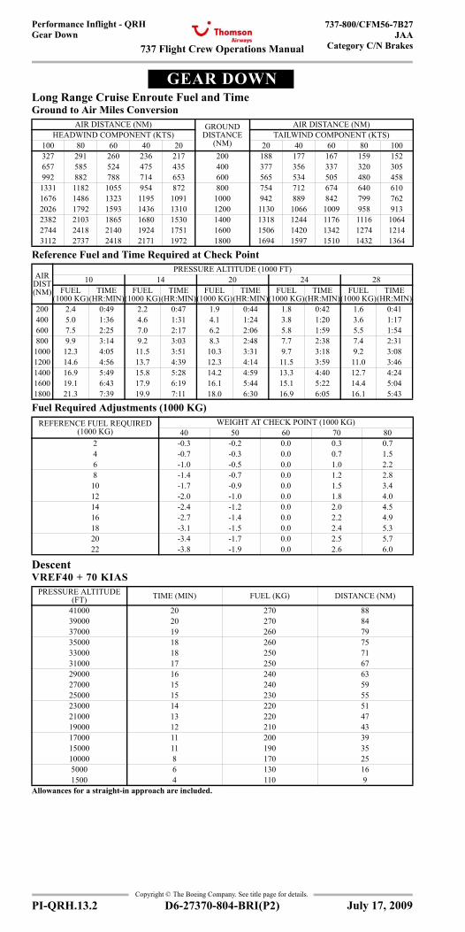
737 Flight Crew Operations Manual
Performance Inflight - QRHGear Down
737-800/CFM56-7B27JAA
Category C/N Brakes
Copyright © The Boeing Company. See title page for details.
PI-QRH.13.2 D6-27370-804-BRI(P2)
GEAR DOWNGear Down
Long Range Cruise Enroute Fuel and TimeGround to Air Miles Conversion
Reference Fuel and Time Required at Check Point
Fuel Required Adjustments (1000 KG)
DescentVREF40 + 70 KIAS
AIR DISTANCE (NM) GROUND DISTANCE
(NM)
AIR DISTANCE (NM)HEADWIND COMPONENT (KTS) TAILWIND COMPONENT (KTS)
100 80 60 40 20 20 40 60 80 100327 291 260 236 217 200 188 177 167 159 152657 585 524 475 435 400 377 356 337 320 305992 882 788 714 653 600 565 534 505 480 458
1331 1182 1055 954 872 800 754 712 674 640 6101676 1486 1323 1195 1091 1000 942 889 842 799 7622026 1792 1593 1436 1310 1200 1130 1066 1009 958 9132382 2103 1865 1680 1530 1400 1318 1244 1176 1116 10642744 2418 2140 1924 1751 1600 1506 1420 1342 1274 12143112 2737 2418 2171 1972 1800 1694 1597 1510 1432 1364
AIR DIST (NM)
PRESSURE ALTITUDE (1000 FT)10 14 20 24 28
FUEL (1000 KG)
TIME (HR:MIN)
FUEL (1000 KG)
TIME (HR:MIN)
FUEL (1000 KG)
TIME (HR:MIN)
FUEL (1000 KG)
TIME (HR:MIN)
FUEL (1000 KG)
TIME (HR:MIN)
200 2.4 0:49 2.2 0:47 1.9 0:44 1.8 0:42 1.6 0:41400 5.0 1:36 4.6 1:31 4.1 1:24 3.8 1:20 3.6 1:17600 7.5 2:25 7.0 2:17 6.2 2:06 5.8 1:59 5.5 1:54800 9.9 3:14 9.2 3:03 8.3 2:48 7.7 2:38 7.4 2:311000 12.3 4:05 11.5 3:51 10.3 3:31 9.7 3:18 9.2 3:081200 14.6 4:56 13.7 4:39 12.3 4:14 11.5 3:59 11.0 3:461400 16.9 5:49 15.8 5:28 14.2 4:59 13.3 4:40 12.7 4:241600 19.1 6:43 17.9 6:19 16.1 5:44 15.1 5:22 14.4 5:041800 21.3 7:39 19.9 7:11 18.0 6:30 16.9 6:05 16.1 5:43
REFERENCE FUEL REQUIRED (1000 KG)
WEIGHT AT CHECK POINT (1000 KG)40 50 60 70 80
2 -0.3 -0.2 0.0 0.3 0.74 -0.7 -0.3 0.0 0.7 1.56 -1.0 -0.5 0.0 1.0 2.28 -1.4 -0.7 0.0 1.2 2.810 -1.7 -0.9 0.0 1.5 3.412 -2.0 -1.0 0.0 1.8 4.014 -2.4 -1.2 0.0 2.0 4.516 -2.7 -1.4 0.0 2.2 4.918 -3.1 -1.5 0.0 2.4 5.320 -3.4 -1.7 0.0 2.5 5.722 -3.8 -1.9 0.0 2.6 6.0
PRESSURE ALTITUDE (FT) TIME (MIN) FUEL (KG) DISTANCE (NM)
41000 20 270 8839000 20 270 8437000 19 260 7935000 18 260 7533000 18 250 7131000 17 250 6729000 16 240 6327000 15 240 5925000 15 230 5523000 14 220 5121000 13 220 4719000 12 210 4317000 11 200 3915000 11 190 3510000 8 170 255000 6 130 161500 4 110 9
Allowances for a straight-in approach are included.
July 17, 2009
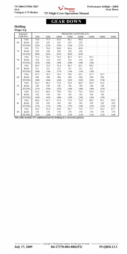
737 Flight Crew Operations Manual
Performance Inflight - QRHGear Down
737-800/CFM56-7B27JAACategory C/N Brakes
Copyright © The Boeing Company. See title page for details.
D6-27370-804-BRI(P2) PI-QRH.13.3
GEAR DOWNGear Down
HoldingFlaps Up
WEIGHT (1000 KG)
PRESSURE ALTITUDE (FT)1500 5000 10000 15000 20000 25000 30000 35000
%N1 74.8 77.5 81.8 86.1 90.880 KIAS 225 225 225 225 225
FF/ENG 2160 2150 2140 2160 2170%N1 73.1 76.0 80.0 84.4 89.0
75 KIAS 220 220 220 220 220FF/ENG 2040 2030 2010 2020 2030
%N1 71.3 74.3 78.2 82.5 87.1 93.170 KIAS 216 216 216 216 216 216
FF/ENG 1920 1900 1890 1890 1890 1940%N1 69.5 72.4 76.4 80.7 85.1 90.2
65 KIAS 211 211 211 211 211 211FF/ENG 1800 1780 1770 1760 1750 1780
%N1 67.5 70.3 74.5 78.6 83.1 87.7 95.760 KIAS 204 204 204 204 204 204 204
FF/ENG 1680 1660 1640 1630 1620 1630 1740%N1 65.5 68.2 72.4 76.4 80.9 85.5 91.6
55 KIAS 198 198 198 198 198 198 198FF/ENG 1570 1540 1520 1500 1490 1490 1550
%N1 63.3 66.0 70.0 74.2 78.5 83.0 87.950 KIAS 192 192 192 192 192 192 192
FF/ENG 1450 1430 1400 1380 1360 1360 1390%N1 60.8 63.7 67.6 71.8 76.0 80.5 85.1 92.6
45 KIAS 185 185 185 185 185 185 185 185FF/ENG 1330 1310 1290 1270 1240 1230 1250 1320
%N1 58.2 61.0 65.0 69.1 73.4 77.7 82.2 87.740 KIAS 178 178 178 178 178 178 178 178
FF/ENG 1220 1200 1170 1150 1130 1110 1120 1140This table includes 5% additional fuel for holding in a racetrack pattern.
July 17, 2009
737 Flight Crew Operations Manual
Performance Inflight - QRHGear Down
737-800/CFM56-7B27JAA
Category C/N Brakes
Copyright © The Boeing Company. See title page for details.
PI-QRH.13.4 D6-27370-804-BRI(P2)
IntentionallyBlank
July 17, 2009
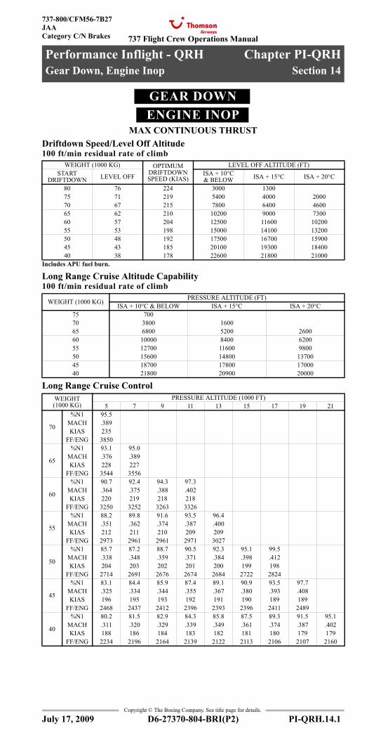
737 Flight Crew Operations Manual
Performance Inflight - QRH Chapter PI-QRHGear Down, Engine Inop Section 14
737-800/CFM56-7B27JAACategory C/N Brakes
Copyright © The Boeing Company. See title page for details.
D6-27370-804-BRI(P2) PI-QRH.14.1
PI-QRH.14 Performance Inflight - QRH-Gear Down, Engine InopGEAR DOWNENGINE INOP
MAX CONTINUOUS THRUSTGear Down, Engine Inoperative
Driftdown Speed/Level Off Altitude100 ft/min residual rate of climb
Long Range Cruise Altitude Capability100 ft/min residual rate of climb
Long Range Cruise Control
WEIGHT (1000 KG) OPTIMUM DRIFTDOWN SPEED (KIAS)
LEVEL OFF ALTITUDE (FT)START
DRIFTDOWN LEVEL OFF ISA + 10°C & BELOW ISA + 15°C ISA + 20°C
80 76 224 3000 130075 71 219 5400 4000 200070 67 215 7800 6400 460065 62 210 10200 9000 730060 57 204 12500 11600 1020055 53 198 15000 14100 1320050 48 192 17500 16700 1590045 43 185 20100 19300 1840040 38 178 22600 21800 21000
Includes APU fuel burn.
WEIGHT (1000 KG) PRESSURE ALTITUDE (FT)ISA + 10°C & BELOW ISA + 15°C ISA + 20°C
75 70070 3800 160065 6800 5200 260060 10000 8400 620055 12700 11600 980050 15600 14800 1370045 18700 17800 1700040 21800 20900 20000
WEIGHT (1000 KG)
PRESSURE ALTITUDE (1000 FT)5 7 9 11 13 15 17 19 21
70
%N1 95.5MACH .389KIAS 235
FF/ENG 3850
65
%N1 93.1 95.0MACH .376 .389KIAS 228 227
FF/ENG 3544 3556
60
%N1 90.7 92.4 94.3 97.3MACH .364 .375 .388 .402KIAS 220 219 218 218
FF/ENG 3250 3252 3263 3326
55
%N1 88.2 89.8 91.6 93.5 96.4MACH .351 .362 .374 .387 .400KIAS 212 211 210 209 209
FF/ENG 2973 2961 2961 2971 3027
50
%N1 85.7 87.2 88.7 90.5 92.3 95.1 99.5MACH .338 .348 .359 .371 .384 .398 .412KIAS 204 203 202 201 200 199 198
FF/ENG 2714 2691 2676 2674 2684 2722 2824
45
%N1 83.1 84.4 85.9 87.4 89.1 90.9 93.5 97.7MACH .325 .334 .344 .355 .367 .380 .393 .408KIAS 196 195 193 192 191 190 189 189
FF/ENG 2468 2437 2412 2396 2393 2396 2411 2489
40
%N1 80.2 81.5 82.9 84.3 85.8 87.5 89.3 91.5 95.1MACH .311 .320 .329 .339 .349 .361 .374 .387 .402KIAS 188 186 184 183 182 181 180 179 179
FF/ENG 2234 2196 2164 2139 2122 2113 2106 2107 2160
July 17, 2009
Gear Down, Engine Inop
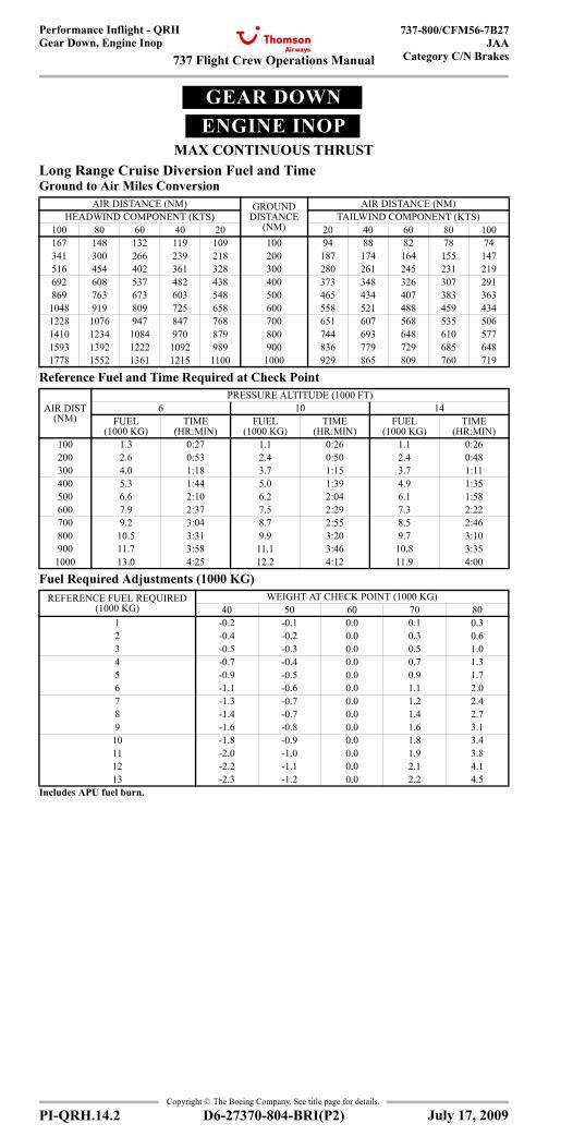
737 Flight Crew Operations Manual
Performance Inflight - QRHGear Down, Engine Inop
737-800/CFM56-7B27JAA
Category C/N Brakes
Copyright © The Boeing Company. See title page for details.
PI-QRH.14.2 D6-27370-804-BRI(P2)
GEAR DOWNENGINE INOP
MAX CONTINUOUS THRUSTGear Down, Engine Inoperative
Long Range Cruise Diversion Fuel and TimeGround to Air Miles Conversion
Reference Fuel and Time Required at Check Point
Fuel Required Adjustments (1000 KG)
AIR DISTANCE (NM) GROUND DISTANCE
(NM)
AIR DISTANCE (NM)HEADWIND COMPONENT (KTS) TAILWIND COMPONENT (KTS)
100 80 60 40 20 20 40 60 80 100167 148 132 119 109 100 94 88 82 78 74341 300 266 239 218 200 187 174 164 155 147516 454 402 361 328 300 280 261 245 231 219692 608 537 482 438 400 373 348 326 307 291869 763 673 603 548 500 465 434 407 383 363
1048 919 809 725 658 600 558 521 488 459 4341228 1076 947 847 768 700 651 607 568 535 5061410 1234 1084 970 879 800 744 693 648 610 5771593 1392 1222 1092 989 900 836 779 729 685 6481778 1552 1361 1215 1100 1000 929 865 809 760 719
AIR DIST (NM)
PRESSURE ALTITUDE (1000 FT)6 10 14
FUEL (1000 KG)
TIME (HR:MIN)
FUEL (1000 KG)
TIME (HR:MIN)
FUEL (1000 KG)
TIME (HR:MIN)
100 1.3 0:27 1.1 0:26 1.1 0:26200 2.6 0:53 2.4 0:50 2.4 0:48300 4.0 1:18 3.7 1:15 3.7 1:11400 5.3 1:44 5.0 1:39 4.9 1:35500 6.6 2:10 6.2 2:04 6.1 1:58600 7.9 2:37 7.5 2:29 7.3 2:22700 9.2 3:04 8.7 2:55 8.5 2:46800 10.5 3:31 9.9 3:20 9.7 3:10900 11.7 3:58 11.1 3:46 10.8 3:35
1000 13.0 4:25 12.2 4:12 11.9 4:00
REFERENCE FUEL REQUIRED (1000 KG)
WEIGHT AT CHECK POINT (1000 KG)40 50 60 70 80
1 -0.2 -0.1 0.0 0.1 0.32 -0.4 -0.2 0.0 0.3 0.63 -0.5 -0.3 0.0 0.5 1.04 -0.7 -0.4 0.0 0.7 1.35 -0.9 -0.5 0.0 0.9 1.76 -1.1 -0.6 0.0 1.1 2.07 -1.3 -0.7 0.0 1.2 2.48 -1.4 -0.7 0.0 1.4 2.79 -1.6 -0.8 0.0 1.6 3.110 -1.8 -0.9 0.0 1.8 3.411 -2.0 -1.0 0.0 1.9 3.812 -2.2 -1.1 0.0 2.1 4.113 -2.3 -1.2 0.0 2.2 4.5
Includes APU fuel burn.
July 17, 2009
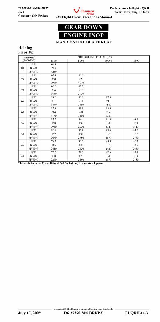
737 Flight Crew Operations Manual
Performance Inflight - QRHGear Down, Engine Inop
737-800/CFM56-7B27JAACategory C/N Brakes
Copyright © The Boeing Company. See title page for details.
D6-27370-804-BRI(P2) PI-QRH.14.3
GEAR DOWNENGINE INOP
MAX CONTINUOUS THRUSTGear Down, Engine Inoperative
HoldingFlaps Up
WEIGHT (1000 KG)
PRESSURE ALTITUDE (FT)1500 5000 10000 15000
%N1 94.180 KIAS 225
FF/ENG 4240%N1 92.1 95.5
75 KIAS 220 220FF/ENG 3960 4010
%N1 90.0 93.370 KIAS 216 216
FF/ENG 3680 3730%N1 88.0 91.1 97.0
65 KIAS 211 211 211FF/ENG 3430 3450 3560
%N1 85.8 88.8 93.660 KIAS 204 204 204
FF/ENG 3170 3180 3230%N1 83.5 86.4 91.0 98.4
55 KIAS 198 198 198 198FF/ENG 2920 2920 2940 3110
%N1 80.9 83.9 88.3 93.650 KIAS 192 192 192 192
FF/ENG 2670 2660 2670 2730%N1 78.3 81.2 85.5 90.2
45 KIAS 185 185 185 185FF/ENG 2440 2420 2420 2450
%N1 75.6 78.3 82.6 87.140 KIAS 178 178 178 178
FF/ENG 2210 2190 2170 2180This table includes 5% additional fuel for holding in a racetrack pattern.
July 17, 2009
737 Flight Crew Operations Manual
Performance Inflight - QRHGear Down, Engine Inop
737-800/CFM56-7B27JAA
Category C/N Brakes
Copyright © The Boeing Company. See title page for details.
PI-QRH.14.4 D6-27370-804-BRI(P2)
IntentionallyBlank
July 17, 2009
737 Flight Crew Operations Manual
Performance Inflight - QRH Chapter PI-QRHText Section 15
737-800/CFM56-7B27JAACategory C/N Brakes
Copyright © The Boeing Company. See title page for details.
D6-27370-804-BRI(P2) PI-QRH.15.1
PI-QRH.15 Performance Inflight - QRH-TextText
IntroductionThis chapter contains information to supplement performance data fromthe Flight Management Computer (FMC). In addition, sufficient inflightdata is provided to complete a flight with the FMC inoperative. In the eventof conflict between data presented in this chapter and that contained in theapproved Airplane Flight Manual, the Flight Manual shall always takeprecedence.
General
Flight with Unreliable Airspeed / Turbulent Air PenetrationPitch attitude and average %N1 information is provided for use in allphases of flight in the event of unreliable airspeed/Mach indicationsresulting from blocking or freezing of the pitot system. Loss of radome orturbulent air may also cause unreliable airspeed/Mach indications. Thecruise table in this section may also be used for turbulent air penetration.Pitch attitude is shown in bold type for emphasis since altitude and/orvertical speed indications may also be unreliable.
Max Climb %N1This table shows Max Climb %N1 for a 280/.78 climb speed schedule,normal engine bleed for packs on or off and anti-ice off. Enter the tablewith airport pressure altitude and TAT and read %N1. %N1 adjustmentsare shown for anti-ice operation.
Go-around %N1To find Max Go-around %N1 based on normal engine bleed for packs on(AUTO) and anti-ice on or off, enter the Go-around %N1 table with airportpressure altitude and reported OAT or TAT and read %N1. For packs OFFor HIGH operation, apply the %N1 adjustment shown below the table.
VREFThis table contains flaps 40, 30 and 15 reference speeds for a given weight.With autothrottles disengaged an approach speed wind correction (max 20knots) of 1/2 steady headwind component + gust increment above steadywind is recommended. Do not apply a wind correction for tailwinds. Themaximum command speed should not exceed landing flap placard speedminus 5 knots.
Advisory Information
Normal Configuration Landing DistanceThe normal configuration distance tables are provided as advisoryinformation to help determine the actual landing distance performance ofthe airplane for different runway surface conditions and brakeconfigurations.Flaps 30 and 40 landing distances and adjustments are provided for dryrunways as well as runways with good, medium, and poor reported brakingactions, which are commonly referred to as slippery runway conditions.Landing distances for slippery runways are 115% of the actual landingdistances.
July 17, 2009
Text
737 Flight Crew Operations Manual
Performance Inflight - QRHText
737-800/CFM56-7B27JAA
Category C/N Brakes
Copyright © The Boeing Company. See title page for details.
PI-QRH.15.2 D6-27370-804-BRI(P2)
If the surface is affected by water, snow or ice, and the braking action isreported as "good", conditions should not be expected to be as good as onclean, dry runways. The value "good" is comparative and is intended tomean that airplanes should not experience braking or directional controldifficulties when landing. The performance level used to calculate the"good" data is consistent with wet runway testing done on early Boeingjets. The performance level used to calculate "poor" data reflects runwayscovered with wet ice.Dry runway landing performance is shown for max manual brakingconfiguration and autobrake settings max, 3, 2, and 1. Use of autobrakesetting 1 is not recommended for landings on slippery runways, and istherefore not provided for these conditions. The autobrake performancemay be used to assist in the selection of the most desirable autobrakesetting for a given field length. Selection of an autobrake setting results ina constant rate of deceleration. Maximum effort manual braking shouldachieve shorter landing distance than the max autobrake setting. Thereference landing distance is a reference distance from 50 ft above thethreshold to stop based on a reference landing weight and normal approachspeed for the selected landing flap at sea level, zero wind, zero slope, andtwo engine detent reverse thrust. Subsequent columns provide adjustmentsfor off-reference landing weight, altitude, wind, slope, temperature, speed,and reverse thrust. Each adjustment is independently added to thereference landing distance.
Non-normal Configuration Landing DistanceAdvisory information is provided to support non-normal configurationsthat affect the landing performance of the airplane. Landing distances andadjustments are provided for dry runways and runways with good,medium, and poor reported braking action.Enter the table with the applicable non-normal configuration and read thenormal approach speed. The reference landing distance is a referencedistance from 50 ft above the threshold to stop based on a reference landingweight and speed at sea level, zero wind, and zero slope. Subsequentcolumns provide adjustments for off-reference landing weight, altitude,wind, slope, and speed conditions. Each adjustment is independentlyadded to the reference landing distance. Landing distance includes theeffect of max manual braking and reverse thrust.
Recommended Brake Cooling ScheduleAdvisory information is provided to assist in avoiding the problemsassociated with hot brakes. For normal operation, most landings are atweights below the AFM quick turnaround limit weight.Use of the recommended cooling schedule will help avoid brake overheatand fuse plug problems that could result from repeated landings at shorttime intervals or a rejected takeoff.Enter the appropiate Recommended Brake Cooling Schedule table (Steelor Carbon Brakes) with the airplane weight and brakes on speed, adjustedfor wind at the appropriate temperature and altitude condition. Instructionsfor applying wind adjustments are included below the table. Linearinterpolation may be used to obtain intermediate values. The resultingnumber is the reference brake energy per brake in millions of foot-pounds,and represents the amount of energy absorbed by each brake during arejected takeoff. Notes providing adjustments for wind are included belowthe table.
July 17, 2009
737 Flight Crew Operations Manual
Performance Inflight - QRHText
737-800/CFM56-7B27JAACategory C/N Brakes
Copyright © The Boeing Company. See title page for details.
D6-27370-804-BRI(P2) PI-QRH.15.3
To determine the energy per brake absorbed during landing, enter theappropriate Adjusted Brake Energy Per Brake table (No Reverse Thrust or2 Engine Reverse) with the reference brake energy per brake and the typeof braking used during landing (Max Manual, Max Auto, or Autobrake).The resulting number is the adjusted brake energy per brake and representsthe energy absorbed in each brake during the landing.The recommended cooling time is found in the final table by entering withthe adjusted brake energy per brake. Times are provided for groundcooling and inflight gear down cooling.Brake Temperature Monitor System (BTMS) indications are also shown. Ifbrake cooling is determined from the BTMS, use the hottest brakeindication 10 to 15 minutes after the airplane has come to a complete stop,or inflight with gear retracted to determine recommended coolingschedule.
Engine Inoperative
Initial Max Continuous %N1The Initial Max Continuous %N1 setting for use following an enginefailure is shown. The table is based on the typical all engine cruise speedof .79M to provide a target %N1 setting at the start of driftdown. Oncedriftdown is established, the Max Continuous %N1 table should be used todetermine %N1 for the given conditions.
Max Continuous %N1Power setting is based on one engine operating with one A/C packoperating and all anti-ice bleeds off. Enter the table with pressure altitude,TAT, and IAS or Mach to read %N1.It is desirable to maintain engine thrust level within the limits of the MaxCruise thrust rating. However, where thrust level in excess of Max Cruiserating is required, such as for meeting terrain clearance, ATC altitudeassignments, or to attain maximum range capability, it is permissible to usethe thrust needed up to the Max Continuous thrust rating. The MaxContinuous thrust rating is intended primarily for emergency use at thediscretion of the pilot and is the maximum thrust that may be usedcontinuously.
Driftdown Speed/Level Off AltitudeThe table shows optimum driftdown speed as a function of cruise weightat start of driftdown. Also shown are the approximate weight and pressurealtitude at which the airplane will level off considering 100 ft/min residualrate of climb. The level off altitude is dependent on air temperature (ISA deviation).
Driftdown/LRC Range CapabilityThis table shows the range capability from the start of driftdown.Driftdown is continued to level off altitude. As weight decreases due tofuel burn, the airplane is accelerated to Long Range Cruise speed. Cruiseis continued at level off altitude and Long Range Cruise speed.To determine fuel required, enter the Ground to Air Miles Conversion tablewith the desired ground distance and adjust for anticipated winds to obtainair distance to destination. Then enter the Driftdown/Cruise Fuel and Timetable with air distance and weight at start of driftdown to determine fuel
July 17, 2009
737 Flight Crew Operations Manual
Performance Inflight - QRHText
737-800/CFM56-7B27JAA
Category C/N Brakes
Copyright © The Boeing Company. See title page for details.
PI-QRH.15.4 D6-27370-804-BRI(P2)
and time required. If altitudes other than the level off altitude is used, fueland time required may be obtained by using the Engine Inoperative LongRange Cruise Enroute Fuel and Time table.
Long Range Cruise Altitude CapabilityThe table shows the maximum altitude that can be maintained at a givenweight and air temperature (ISA deviation), based on Long Range Cruisespeed, Max Continuous thrust, and 100 ft/min residual rate of climb.
Long Range Cruise ControlThe table provides target %N1, engine inoperative Long Range CruiseMach number, IAS and fuel flow for the airplane weight and pressurealtitude. The fuel flow values in this table reflect single engine fuel burn.
Long Range Cruise Diversion Fuel and TimeTables are provided for crews to determine the fuel and time required toproceed to an alternate airfield with one engine inoperative. The data isbased on single engine Long Range Cruise speed and .78/280/250 descent.Enter with Air Distance as determined from the Ground to Air MilesConversion table and read Fuel and Time required at the cruise pressurealtitude. Adjust the fuel obtained for deviation from the reference weightat checkpoint as required by entering the off reference fuel adjustmentstable with the fuel required for the reference weight and the actual weightat checkpoint. Read fuel required and time for the actual weight.
HoldingTarget %N1, indicated airspeed and fuel flow per engine information istabulated for holding with flaps up based on the FMC optimum holdingspeed schedule. This is the higher of the maximum endurance speed andthe maneuvering speed. Small variations in airspeed will not appreciablyaffect the overall endurance time. Enter the table with weight and pressurealtitude to read %N1, IAS and fuel flow per engine.
Gear DownThis section contains performance for airplane operation with the landinggear extended. The data is based on engine bleeds for normal airconditioning.Note: The Flight Management Computer System (FMCS) does not containspecial provisions for operation with landing gear extended. As a result,the FMCS may generate inappropriate enroute speed schedules, displaynon-conservative predictions of fuel burn, estimated time of arrival (ETA),maximum altitude, and compute overly shallow descent path. An accurateestimated time of arrival (ETA) is available if current speed or Mach isentered into the VNAV cruise page. Tables for gear down performance in this section are identical in formatand used in the same manner as tables for the gear up configurationpreviously described.
July 17, 2009
737 Flight Crew Operations Manual
Performance Inflight - QRH Chapter PI-QRHGeneral Section 20
Copyright © The Boeing Company. See title page for details.
D6-27370-804-BRI(P2) PI-QRH.TOC.20.1
737-800WSFP1 CFM56-7B27 KG JAA CATC/N (FMC Model 737-800W.1)
737-800WSFP1 CFM56-7B27 KG JAA CATC/N (FMC Model 737-800W.1)
General . . . . . . . . . . . . . . . . . . . . . . . . . . . . . . . . . . . . . . . PI-QRH.20.1
Flight With Unreliable Airspeed/ Turbulent Air Penetration . . . . . . . . . . . . . . . . . . . . . . . . . . . . . . . . . PI-QRH.20.1Max Climb %N1 . . . . . . . . . . . . . . . . . . . . . . . . . . . . . PI-QRH.20.3Go-around %N1 . . . . . . . . . . . . . . . . . . . . . . . . . . . . . PI-QRH.20.3VREF . . . . . . . . . . . . . . . . . . . . . . . . . . . . . . . . . . . . . PI-QRH.20.4
Advisory Information . . . . . . . . . . . . . . . . . . . . . . . . . . . . PI-QRH.21.1Normal Configuration Landing Distances . . . . . . . . . PI-QRH.21.1Non-Normal Configuration Landing Distance . . . . . . PI-QRH.21.3Recommended Brake Cooling Schedule . . . . . . . . . . PI-QRH.21.11
Engine Inoperative . . . . . . . . . . . . . . . . . . . . . . . . . . . . . . PI-QRH.22.1Initial Max Continuous %N1 . . . . . . . . . . . . . . . . . . . PI-QRH.22.1Max Continuous %N1 . . . . . . . . . . . . . . . . . . . . . . . . PI-QRH.22.2Driftdown Speed/Level Off Altitude . . . . . . . . . . . . . PI-QRH.22.6Driftdown/LRC Cruise Range Capability . . . . . . . . . PI-QRH.22.6Long Range Cruise Altitude Capability . . . . . . . . . . . PI-QRH.22.7Long Range Cruise Control . . . . . . . . . . . . . . . . . . . . PI-QRH.22.7Long Range Cruise Diversion Fuel and Time . . . . . . PI-QRH.22.8Holding . . . . . . . . . . . . . . . . . . . . . . . . . . . . . . . . . . . . PI-QRH.22.9Gear Down Landing Rate of Climb Available . . . . . PI-QRH.22.10
Gear Down . . . . . . . . . . . . . . . . . . . . . . . . . . . . . . . . . . . . PI-QRH.23.1Long Range Cruise Altitude Capability . . . . . . . . . . . PI-QRH.23.1Long Range Cruise Control . . . . . . . . . . . . . . . . . . . . PI-QRH.23.1Long Range Cruise Enroute Fuel and Time . . . . . . . . PI-QRH.23.2Descent . . . . . . . . . . . . . . . . . . . . . . . . . . . . . . . . . . . . PI-QRH.23.2Holding . . . . . . . . . . . . . . . . . . . . . . . . . . . . . . . . . . . . PI-QRH.23.3
Gear Down, Engine Inoperative . . . . . . . . . . . . . . . . . . . PI-QRH.24.1Driftdown Speed/Level Off Altitude . . . . . . . . . . . . . PI-QRH.24.1Long Range Cruise Altitude Capability . . . . . . . . . . . PI-QRH.24.1Long Range Cruise Control . . . . . . . . . . . . . . . . . . . . PI-QRH.24.1Long Range Cruise Diversion Fuel and Time . . . . . . PI-QRH.24.2Holding . . . . . . . . . . . . . . . . . . . . . . . . . . . . . . . . . . . . PI-QRH.24.3
Text . . . . . . . . . . . . . . . . . . . . . . . . . . . . . . . . . . . . . . . . . . . PI-QRH.25.1Introduction . . . . . . . . . . . . . . . . . . . . . . . . . . . . . . . . PI-QRH.25.1General . . . . . . . . . . . . . . . . . . . . . . . . . . . . . . . . . . . . PI-QRH.25.1Advisory Information . . . . . . . . . . . . . . . . . . . . . . . . . PI-QRH.25.1Engine Inoperative . . . . . . . . . . . . . . . . . . . . . . . . . . . PI-QRH.25.3Gear Down . . . . . . . . . . . . . . . . . . . . . . . . . . . . . . . . . PI-QRH.25.4
July 17, 2009
737-800WSFP1 CFM56-7B27 KG JAA CATC/N (FMC Model 737-800W.1)General
737 Flight Crew Operations Manual
Copyright © The Boeing Company. See title page for details.
PI-QRH.TOC.20.2 D6-27370-804-BRI(P2)
Performance Inflight - QRH -General
IntentionallyBlank
July 17, 2009
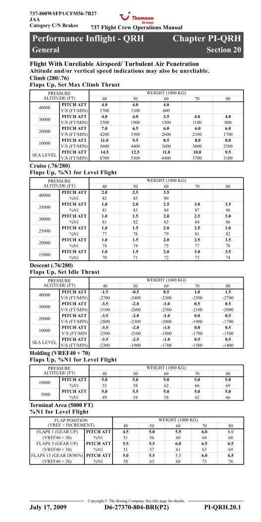
737 Flight Crew Operations Manual
Performance Inflight - QRH Chapter PI-QRHGeneral Section 20
737-800WSFP1/CFM56-7B27JAACategory C/N Brakes
Copyright © The Boeing Company. See title page for details.
D6-27370-804-BRI(P2) PI-QRH.20.1
PI-QRH.20 Performance Inflight - QRH-GeneralGeneral
Flight With Unreliable Airspeed/ Turbulent Air PenetrationAltitude and/or vertical speed indications may also be unreliable. Climb (280/.76) Flaps Up, Set Max Climb Thrust
Cruise (.76/280)Flaps Up, %N1 for Level Flight
Descent (.76/280)Flaps Up, Set Idle Thrust
Holding (VREF40 + 70)Flaps Up, %N1 for Level Flight
Terminal Area (5000 FT)%N1 for Level Flight
PRESSURE ALTITUDE (FT)
WEIGHT (1000 KG)40 50 60 70 80
40000 PITCH ATT 4.0 4.0 4.0V/S (FT/MIN) 1700 1100 600
30000 PITCH ATT 4.0 4.0 3.5 4.0 4.0V/S (FT/MIN) 2500 1900 1500 1100 800
20000 PITCH ATT 7.0 6.5 6.0 6.0 6.0V/S (FT/MIN) 4200 3300 2600 2100 1700
10000 PITCH ATT 11.0 9.5 8.5 8.0 8.0V/S (FT/MIN) 5600 4400 3600 3000 2500
SEA LEVEL PITCH ATT 14.5 12.5 11.0 10.0 9.5V/S (FT/MIN) 6700 5300 4400 3700 3100
PRESSURE ALTITUDE (FT)
WEIGHT (1000 KG)40 50 60 70 80
40000 PITCH ATT 2.0 2.5 3.5%N1 83 85 90
35000 PITCH ATT 1.0 2.0 2.5 3.0 3.5%N1 81 83 84 87 90
30000 PITCH ATT 1.0 1.5 2.0 2.5 3.0%N1 81 82 83 84 86
25000 PITCH ATT 1.0 1.5 2.0 2.5 3.0%N1 77 78 79 81 82
20000 PITCH ATT 1.0 1.5 2.0 2.5 3.5%N1 74 74 75 77 78
15000 PITCH ATT 1.0 1.5 2.0 3.0 3.5%N1 70 71 72 73 74
PRESSURE ALTITUDE (FT)
WEIGHT (1000 KG) 40 50 60 70 80
40000 PITCH ATT -1.5 -0.5 0.5 1.0 1.5V/S (FT/MIN) -2700 -2400 -2300 -2500 -2700
30000 PITCH ATT -3.5 -2.0 -1.0 0.5 0.5V/S (FT/MIN) -3100 -2600 -2300 -2100 -2000
20000 PITCH ATT -3.5 -2.0 -1.0 0.0 0.5V/S (FT/MIN) -2800 -2300 -2000 -1900 -1700
10000 PITCH ATT -3.5 -2.0 -1.0 0.0 0.5V/S (FT/MIN -2500 -2100 -1800 -1700 -1500
SEA LEVEL PITCH ATT -3.5 -2.5 -1.0 0.5 0.5V/S (FT/MIN) -2300 -1900 -1700 -1500 -1400
PRESSURE ALTITUDE (FT)
WEIGHT (1000 KG)40 50 60 70 80
10000 PITCH ATT 5.0 5.0 5.0 5.0 5.0%N1 53 58 62 66 69
5000 PITCH ATT 5.0 5.5 5.0 5.0 5.0%N1 49 54 58 62 66
FLAP POSITION (VREF + INCREMENT)
WEIGHT (1000 KG)40 50 60 70 80
FLAPS 1 (GEAR UP) PITCH ATT 4.5 5.0 5.5 6.0 6.0(VREF40 + 50) %N1 51 56 60 64 68
FLAPS 5 (GEAR UP) PITCH ATT 5.5 5.5 6.0 6.5 6.5(VREF40 + 30) %N1 51 57 61 65 69
FLAPS 15 (GEAR DOWN) PITCH ATT 5.0 5.5 5.5 6.0 6.5(VREF40 + 20) %N1 58 63 68 73 76
July 17, 2009
General - Flight With Unreliable Airspeed
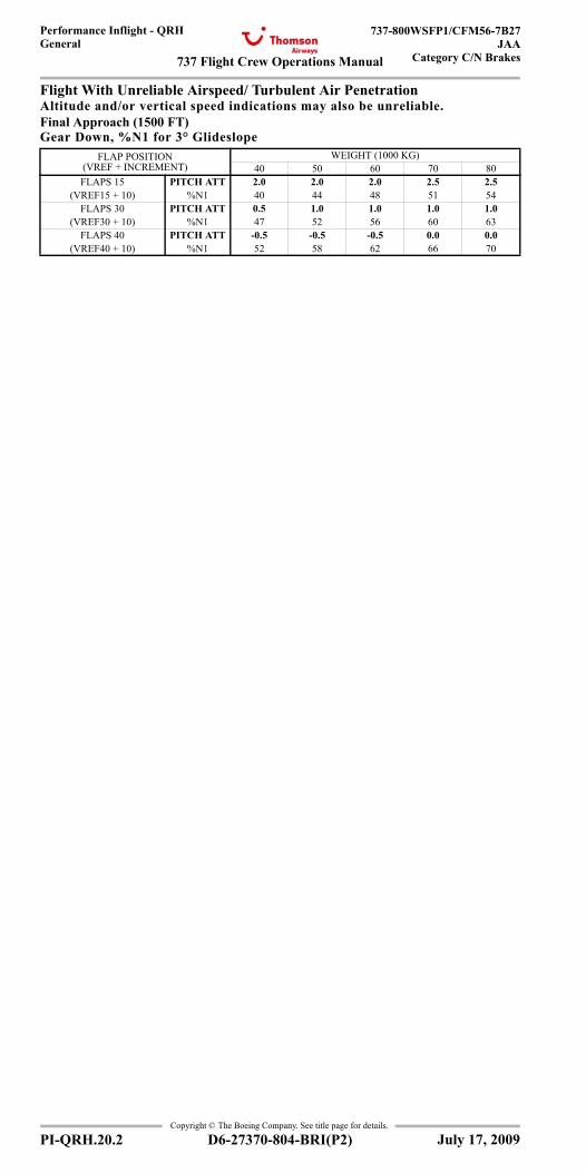
737 Flight Crew Operations Manual
Performance Inflight - QRHGeneral
737-800WSFP1/CFM56-7B27JAA
Category C/N Brakes
Copyright © The Boeing Company. See title page for details.
PI-QRH.20.2 D6-27370-804-BRI(P2)
General
Flight With Unreliable Airspeed/ Turbulent Air PenetrationAltitude and/or vertical speed indications may also be unreliable. Final Approach (1500 FT)Gear Down, %N1 for 3° Glideslope
FLAP POSITION (VREF + INCREMENT)
WEIGHT (1000 KG)40 50 60 70 80
FLAPS 15 PITCH ATT 2.0 2.0 2.0 2.5 2.5(VREF15 + 10) %N1 40 44 48 51 54
FLAPS 30 PITCH ATT 0.5 1.0 1.0 1.0 1.0(VREF30 + 10) %N1 47 52 56 60 63
FLAPS 40 PITCH ATT -0.5 -0.5 -0.5 0.0 0.0(VREF40 + 10) %N1 52 58 62 66 70
July 17, 2009
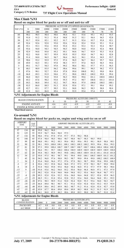
737 Flight Crew Operations Manual
Performance Inflight - QRHGeneral
737-800WSFP1/CFM56-7B27JAACategory C/N Brakes
Copyright © The Boeing Company. See title page for details.
D6-27370-804-BRI(P2) PI-QRH.20.3
Max Climb %N1Based on engine bleed for packs on or off and anti-ice off
%N1 Adjustments for Engine Bleeds
Go-around %N1Based on engine bleed for packs on, engine and wing anti-ice on or off
%N1 Adjustments for Engine Bleeds
TAT (°C)PRESSURE ALTITUDE (FT)/SPEED (KIAS/MACH)
0 5000 10000 15000 20000 25000 30000 35000 37000 41000280 280 280 280 280 280 280 .78 .78 .78
60 90.2 90.5 90.4 90.6 90.4 92.1 93.8 95.1 95.2 93.555 91.0 91.2 91.3 91.4 90.8 91.5 93.1 94.4 94.5 92.850 91.7 92.0 92.1 92.2 91.7 91.5 92.4 93.7 93.8 92.145 92.4 92.6 92.8 93.0 92.6 92.4 92.4 93.0 93.1 91.440 93.1 93.3 93.6 93.8 93.4 93.2 93.2 92.3 92.4 90.735 93.6 94.0 94.3 94.5 94.3 94.0 94.0 93.0 92.4 90.830 92.9 94.8 95.0 95.2 95.1 94.8 94.7 93.9 93.3 91.825 92.2 94.8 95.7 95.9 95.9 95.5 95.4 94.7 94.1 92.820 91.4 94.0 96.5 96.7 96.6 96.2 96.1 95.4 94.9 93.715 90.6 93.2 95.9 97.5 97.4 96.9 96.7 96.2 95.7 94.610 89.9 92.5 95.1 97.8 98.3 97.7 97.4 96.9 96.5 95.65 89.1 91.7 94.3 97.0 99.2 98.6 98.1 97.7 97.3 96.50 88.3 90.9 93.5 96.2 98.6 99.6 99.1 98.5 98.2 97.5-5 87.6 90.1 92.7 95.4 97.8 99.6 100.0 99.2 99.0 98.4
-10 86.8 89.3 91.9 94.6 97.1 98.8 100.3 100.2 99.8 99.4-15 86.0 88.5 91.0 93.8 96.3 98.0 99.6 101.1 100.8 100.4-20 85.2 87.6 90.2 93.0 95.5 97.2 98.7 100.8 101.3 101.0-25 84.3 86.8 89.4 92.2 94.7 96.4 97.9 100.0 100.5 100.1-30 83.5 86.0 88.5 91.3 93.9 95.6 97.1 99.1 99.6 99.3-35 82.7 85.1 87.7 90.5 93.1 94.8 96.3 98.3 98.8 98.4-40 81.8 84.3 86.8 89.6 92.3 93.9 95.4 97.4 97.9 97.6
BLEED CONFIGURATION PRESSURE ALTITUDE (1000 FT)0 10 20 30 35 41
ENGINE ANTI-ICE -0.6 -0.8 -0.9 -0.9 -0.8 -0.8ENGINE & WING ANTI-ICE* -1.8 -2.1 -2.5 -2.7 -3.0 -3.0
*Dual bleed sources
AIRPORT OAT TAT
(°C)AIRPORT PRESSURE ALTITUDE (FT)
°C °F -2000 0 1000 2000 3000 4000 5000 6000 7000 8000 9000 1000057 134 60 95.0 96.2 96.852 125 55 95.9 96.7 96.6 96.8 97.547 116 50 96.6 97.6 97.8 97.8 97.7 97.5 98.2 98.842 108 45 97.4 98.4 98.5 98.6 98.7 98.8 98.7 98.5 98.5 99.037 99 40 98.0 99.1 99.2 99.3 99.4 99.5 99.6 99.5 99.1 98.9 98.8 99.132 90 35 98.1 99.9 100.0 100.1 100.1 100.3 100.3 100.2 99.9 99.6 99.6 99.527 81 30 97.3 99.8 100.4 100.7 100.7 100.7 100.7 100.7 100.6 100.4 100.4 100.322 72 25 96.6 99.1 99.7 100.2 100.6 100.9 100.9 100.9 100.9 100.9 100.9 100.817 63 20 95.8 98.3 98.9 99.5 99.8 100.2 100.5 100.9 101.0 101.1 101.0 101.012 54 15 95.0 97.5 98.1 98.7 99.1 99.4 99.8 100.1 100.5 100.9 101.3 101.27 45 10 94.2 96.8 97.4 98.0 98.3 98.7 99.0 99.4 99.8 100.2 100.5 100.92 36 5 93.4 96.0 96.6 97.2 97.6 97.9 98.3 98.7 99.0 99.4 99.8 100.2-3 27 0 92.6 95.2 95.8 96.4 96.8 97.2 97.5 97.9 98.3 98.7 99.0 99.4-8 18 -5 91.8 94.4 95.0 95.6 96.0 96.4 96.8 97.2 97.5 97.9 98.3 98.6
-13 9 -10 91.0 93.6 94.2 94.8 95.2 95.6 96.0 96.4 96.8 97.1 97.5 97.9-17 1 -15 90.2 92.8 93.4 94.0 94.4 94.8 95.2 95.6 96.0 96.4 96.7 97.1-22 -8 -20 89.3 92.0 92.6 93.2 93.6 94.0 94.4 94.8 95.2 95.6 95.9 96.3-27 -17 -25 88.5 91.1 91.8 92.4 92.8 93.2 93.6 94.0 94.4 94.8 95.1 95.5-32 -26 -30 87.6 90.3 90.9 91.6 92.0 92.4 92.8 93.3 93.6 94.0 94.3 94.7-37 -35 -35 86.8 89.4 90.1 90.7 91.1 91.6 92.0 92.4 92.8 93.2 93.5 93.9-42 -44 -40 85.9 88.6 89.2 89.9 90.3 90.7 91.2 91.6 92.0 92.4 92.7 93.0-47 -53 -45 85.0 87.7 88.4 89.0 89.4 89.9 90.3 90.8 91.2 91.5 91.9 92.2-52 -62 -50 84.1 86.8 87.5 88.2 88.6 89.0 89.5 90.0 90.3 90.7 91.0 91.4
BLEED CONFIGURATION
PRESSURE ALTITUDE (FT)-2000 0 1000 2000 3000 4000 5000 6000 7000 8000 9000 10000
PACKS OFF 0.7 0.8 0.8 0.8 0.8 0.9 0.9 0.9 0.9 0.9 0.9 0.9A/C HIGH -0.1 -0.1 -0.1 -0.1 -0.1 -0.1 -0.1 -0.1 -0.1 -0.1 -0.1 -0.1
July 17, 2009
General - Max Climb & Go Around %N1
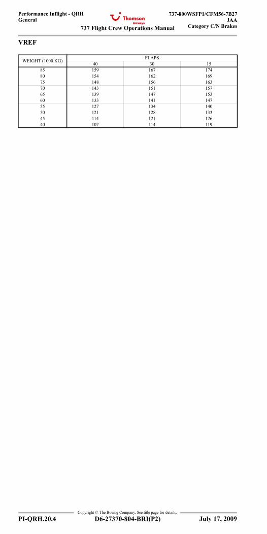
737 Flight Crew Operations Manual
Performance Inflight - QRHGeneral
737-800WSFP1/CFM56-7B27JAA
Category C/N Brakes
Copyright © The Boeing Company. See title page for details.
PI-QRH.20.4 D6-27370-804-BRI(P2)
VREF
WEIGHT (1000 KG) FLAPS40 30 15
85 159 167 17480 154 162 16975 148 156 16370 143 151 15765 139 147 15360 133 141 14755 127 134 14050 121 128 13345 114 121 12640 107 114 119
July 17, 2009
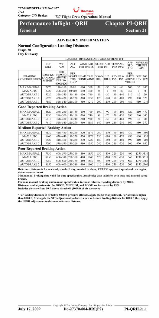
737 Flight Crew Operations Manual
Performance Inflight - QRH Chapter PI-QRHGeneral Section 21
737-800WSFP1/CFM56-7B27JAACategory C/N Brakes
Copyright © The Boeing Company. See title page for details.
D6-27370-804-BRI(P2) PI-QRH.21.1
PI-QRH.21 Performance Inflight - QRH-GeneralADVISORY INFORMATIONAdvisory Information
Normal Configuration Landing DistancesFlaps 30Dry Runway
Good Reported Braking Action
Medium Reported Braking Action
Poor Reported Braking Action
Reference distance is for sea level, standard day, no wind or slope, VREF30 approach speed and two engine detent reverse thrust.Max manual braking data valid for auto speedbrakes. Autobrake data valid for both auto and manual speed-brakes.For max manual braking and manual speedbrakes, increase reference landing distance by 210 ft.Distances and adjustments for GOOD, MEDIUM, and POOR are increased by 15%.Includes distance from 50 ft above threshold (1000 ft of air distance).
*For landing distance at or below 8000 ft pressure altitude, apply the STD adjustment. For altitudes higher than 8000 ft, first apply the STD adjustment to derive a new reference landing distance for 8000 ft then apply the HIGH adjustment to this new reference distance.
LANDING DISTANCE AND ADJUSTMENT (FT)
REF DIST
WT ADJ
ALT ADJ
WIND ADJ PER 10 KTS
SLOPE ADJ PER 1%
TEMP ADJ PER 10°C
APP SPD ADJ
REVERSE THRUST
ADJ
BRAKING CONFIGURATION
60000 KG LANDING WEIGHT
PER 5000 KG ABOVE/BELOW
60000 KG
PER 1000 FT
STD/HIGH*
HEAD WIND
TAIL WIND
DOWNHILL
UP HILL
ABV ISA
BLW ISA
PER 10 KTS ABOVE VREF30
ONE REV
NO REV
MAX MANUAL 2870 190/-160 60/80 -100 360 30 -30 60 -60 200 50 100MAX AUTO 3720 200/-210 80/110 -140 460 0 0 80 -80 350 0 0
AUTOBRAKE 3 5220 320/-350 130/180 -230 760 10 -30 140 -140 510 10 20AUTOBRAKE 2 6620 450/-470 190/250 -300 1030 120 -140 180 -180 490 300 320AUTOBRAKE 1 7180 520/-540 220/300 -350 1210 200 -210 200 -200 480 610 1010
MAX MANUAL 4520 260/-280 120/150 -200 710 100 -90 100 -100 320 210 470MAX AUTO 5030 290/-300 130/160 -210 740 80 -70 120 -120 390 240 540
AUTOBRAKE 3 6010 370/-400 160/210 -260 900 20 -50 160 -160 590 30 70AUTOBRAKE 2 7610 520/-540 220/290 -350 1180 140 -160 210 -210 560 350 370
MAX MANUAL 6130 410/-430 180/240 -320 1170 260 -210 160 -160 430 580 1400MAX AUTO 6460 430/-440 180/250 -320 1170 230 -180 160 -170 490 600 1430
AUTOBRAKE 3 6620 440/-460 180/250 -330 1220 180 -150 170 -180 590 410 1200AUTOBRAKE 2 7790 530/-550 230/300 -380 1350 240 -220 210 -220 560 470 840
MAX MANUAL 7930 600/-590 250/360 -480 1850 630 -410 220 -230 490 1250 3310MAX AUTO 8250 600/-590 250/360 -480 1840 620 -380 220 -230 560 1230 3310
AUTOBRAKE 3 8250 600/-600 260/360 -480 1850 600 -390 220 -240 580 1270 3380AUTOBRAKE 2 8650 600/-600 280/380 -490 1900 610 -400 230 -250 560 1150 2960
July 17, 2009
General
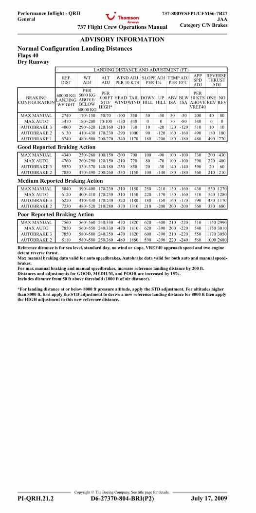
737 Flight Crew Operations Manual
Performance Inflight - QRHGeneral
737-800WSFP1/CFM56-7B27JAA
Category C/N Brakes
Copyright © The Boeing Company. See title page for details.
PI-QRH.21.2 D6-27370-804-BRI(P2)
ADVISORY INFORMATIONAdvisory Information
Normal Configuration Landing DistancesFlaps 40Dry Runway
Good Reported Braking Action
Medium Reported Braking Action
Poor Reported Braking Action
Reference distance is for sea level, standard day, no wind or slope, VREF40 approach speed and two engine detent reverse thrust.Max manual braking data valid for auto speedbrakes. Autobrake data valid for both auto and manual speed-brakes.For max manual braking and manual speedbrakes, increase reference landing distance by 200 ft.Distances and adjustments for GOOD, MEDIUM, and POOR are increased by 15%.Includes distance from 50 ft above threshold (1000 ft of air distance).
*For landing distance at or below 8000 ft pressure altitude, apply the STD adjustment. For altitudes higher than 8000 ft, first apply the STD adjustment to derive a new reference landing distance for 8000 ft then apply the HIGH adjustment to this new reference distance.
LANDING DISTANCE AND ADJUSTMENT (FT)
REF DIST
WT ADJ
ALT ADJ
WIND ADJ PER 10 KTS
SLOPE ADJ PER 1%
TEMP ADJ PER 10°C
APP SPD ADJ
REVERSE THRUST
ADJ
BRAKING CONFIGURATION
60000 KG LANDING WEIGHT
PER 5000 KG ABOVE/BELOW
60000 KG
PER 1000 FT
STD/HIGH*
HEAD WIND
TAIL WIND
DOWNHILL
UP HILL
ABV ISA
BLW ISA
PER 10 KTS ABOVE VREF40
ONE REV
NO REV
MAX MANUAL 2740 170/-150 50/70 -100 350 30 -30 50 -50 200 40 80MAX AUTO 3470 180/-200 70/100 -130 440 0 0 70 -80 340 0 0
AUTOBRAKE 3 4800 290/-320 120/160 -210 730 10 -20 120 -120 510 10 10AUTOBRAKE 2 6130 410/-430 170/230 -290 1000 90 -120 160 -160 490 180 180AUTOBRAKE 1 6740 480/-500 200/270 -340 1170 180 -200 180 -180 480 490 770
MAX MANUAL 4340 250/-260 100/150 -200 700 100 -90 100 -100 330 200 430MAX AUTO 4760 260/-290 120/150 -210 720 80 -70 100 -100 390 220 480
AUTOBRAKE 3 5530 330/-370 140/180 -250 850 20 -30 140 -140 590 20 60AUTOBRAKE 2 7050 470/-490 200/260 -330 1150 100 -140 180 -180 560 210 210
MAX MANUAL 5840 390/-400 170/230 -310 1150 250 -210 150 -160 430 530 1270MAX AUTO 6120 400/-410 170/230 -310 1150 220 -170 150 -160 510 540 1280
AUTOBRAKE 3 6220 410/-430 170/240 -320 1180 180 -150 160 -170 590 430 1170AUTOBRAKE 2 7230 480/-520 210/280 -370 1310 210 -200 200 -200 560 330 680
MAX MANUAL 7560 560/-560 240/330 -470 1820 620 -400 210 -220 510 1150 2990MAX AUTO 7850 560/-550 240/330 -470 1810 620 -390 200 -220 540 1150 3010
AUTOBRAKE 3 7850 580/-580 240/350 -470 1820 600 -390 210 -220 550 1170 3050AUTOBRAKE 2 8110 580/-580 250/360 -480 1860 590 -390 220 -240 560 1000 2680
July 17, 2009

737 Flight Crew Operations Manual
Performance Inflight - QRHGeneral
737-800WSFP1/CFM56-7B27JAACategory C/N Brakes
Copyright © The Boeing Company. See title page for details.
D6-27370-804-BRI(P2) PI-QRH.21.3
ADVISORY INFORMATIONAdvisory Information
Non-Normal Configuration Landing DistanceDry Runway
LANDING DISTANCE AND ADJUSTMENT (FT)
REF DIST FOR
60000 KG LANDING WEIGHT
WT ADJ PER
5000 KG ABV/BLW 60000 KG
ALT ADJ PER
1000 FT STD/HIGH*
WIND ADJ PER 10 KTS
SLOPE ADJ PER 1% APP SPD
LANDING CONFIGURATION VREF HEAD
WINDTAIL
WINDDOWN HILL
UP HILL
PER 10 KTS ABOVE VREF
ALL FLAPS UP VREF40+55 3985 525/-245 80/195 -130 445 50 -35 260ANTI SKID
INOPERATIVE (FLAPS 40)
VREF40 4805 280/-295 130/165 -230 855 130 -115 360
HYDRAULICS - LOSS OF
SYSTEM A (FLAPS 15)
VREF15 3280 230/-180 80/100 -115 395 35 -35 260
HYDRAULICS - LOSS OF
SYSTEM A (FLAPS 30)
VREF30 3165 215/-165 65/80 -115 375 35 -35 280
HYDRAULICS - LOSS OF
SYSTEM A (FLAPS 40)
VREF40 3035 180/-165 65/80 -115 375 35 -35 295
HYDRAULICS - LOSS OF
SYSTEM B (FLAPS 15)
VREF15 3365 180/-180 80/100 -130 445 50 -50 245
HYDRAULICS - MANUAL
REVERSION (LOSS OF BOTH SYSTEM A & B)
VREF15 4575 245/-260 115/150 -180 605 100 -100 475
LEADING EDGE FLAPS TRANSIT VREF15+15 3345 245/-195 80/100 -115 395 35 -35 215
ONE ENGINE INOPERATIVE
(FLAPS 15)VREF15 3020 215/-180 65/80 -115 375 35 -35 215
ONE ENGINE INOPERATIVE (FLAPS 30)**
VREF30 2885 180/-165 65/80 -100 360 35 -35 215
Reference distance assumes sea level, standard day, with no wind or slope.Actual (unfactored) distances are shown.Includes distance from 50 ft above runway threshold (1000 ft of air distance).Assumes maximum manual braking and maximum reverse thrust when available on operating engine(s).Altitude adjustment for STD altitudes valid up to 8000 ft pressure altitude.Altitude adjustment for HIGH altitudes valid for altitudes above 8000 ft up to 14000 ft.
*For landing distance above 8000 ft pressure altitude, first apply the STD altitude adjustment to derive new reference landing distance for 8000 ft, then apply applicable HIGH altitude adjustment between 8000 ft and 14000 ft to this new reference distance.
**ONE ENGINE INOPERATIVE (FLAPS 30) data are only applicable to Fail Operational airplanes.
July 17, 2009
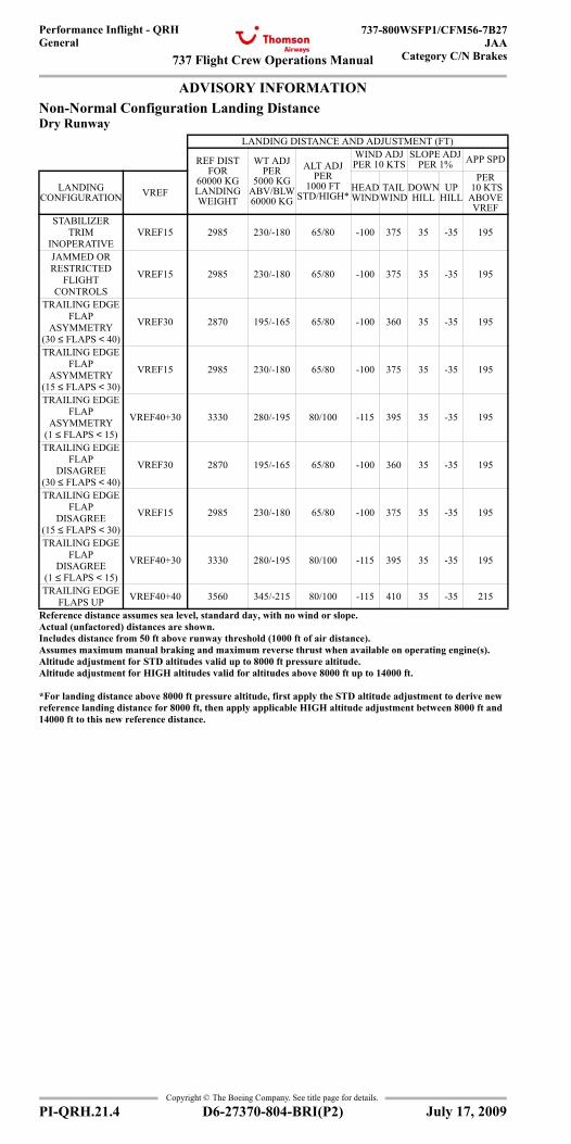
737 Flight Crew Operations Manual
Performance Inflight - QRHGeneral
737-800WSFP1/CFM56-7B27JAA
Category C/N Brakes
Copyright © The Boeing Company. See title page for details.
PI-QRH.21.4 D6-27370-804-BRI(P2)
ADVISORY INFORMATIONAdvisory Information
Non-Normal Configuration Landing DistanceDry Runway
LANDING DISTANCE AND ADJUSTMENT (FT)
REF DIST FOR
60000 KG LANDING WEIGHT
WT ADJ PER
5000 KG ABV/BLW 60000 KG
ALT ADJ PER
1000 FT STD/HIGH*
WIND ADJ PER 10 KTS
SLOPE ADJ PER 1% APP SPD
LANDING CONFIGURATION VREF HEAD
WINDTAIL
WINDDOWN HILL
UP HILL
PER 10 KTS ABOVE VREF
STABILIZER TRIM
INOPERATIVEVREF15 2985 230/-180 65/80 -100 375 35 -35 195
JAMMED ORRESTRICTED
FLIGHTCONTROLS
VREF15 2985 230/-180 65/80 -100 375 35 -35 195
TRAILING EDGE FLAP
ASYMMETRY (30 ≤ FLAPS < 40)
VREF30 2870 195/-165 65/80 -100 360 35 -35 195
TRAILING EDGE FLAP
ASYMMETRY (15 ≤ FLAPS < 30)
VREF15 2985 230/-180 65/80 -100 375 35 -35 195
TRAILING EDGE FLAP
ASYMMETRY (1 ≤ FLAPS < 15)
VREF40+30 3330 280/-195 80/100 -115 395 35 -35 195
TRAILING EDGE FLAP
DISAGREE (30 ≤ FLAPS < 40)
VREF30 2870 195/-165 65/80 -100 360 35 -35 195
TRAILING EDGE FLAP
DISAGREE (15 ≤ FLAPS < 30)
VREF15 2985 230/-180 65/80 -100 375 35 -35 195
TRAILING EDGE FLAP
DISAGREE (1 ≤ FLAPS < 15)
VREF40+30 3330 280/-195 80/100 -115 395 35 -35 195
TRAILING EDGE FLAPS UP VREF40+40 3560 345/-215 80/100 -115 410 35 -35 215
Reference distance assumes sea level, standard day, with no wind or slope.Actual (unfactored) distances are shown.Includes distance from 50 ft above runway threshold (1000 ft of air distance).Assumes maximum manual braking and maximum reverse thrust when available on operating engine(s).Altitude adjustment for STD altitudes valid up to 8000 ft pressure altitude.Altitude adjustment for HIGH altitudes valid for altitudes above 8000 ft up to 14000 ft.
*For landing distance above 8000 ft pressure altitude, first apply the STD altitude adjustment to derive new reference landing distance for 8000 ft, then apply applicable HIGH altitude adjustment between 8000 ft and 14000 ft to this new reference distance.
July 17, 2009

737 Flight Crew Operations Manual
Performance Inflight - QRHGeneral
737-800WSFP1/CFM56-7B27JAACategory C/N Brakes
Copyright © The Boeing Company. See title page for details.
D6-27370-804-BRI(P2) PI-QRH.21.5
ADVISORY INFORMATIONAdvisory Information
Non-Normal Configuration Landing DistanceGood Reported Braking Action
LANDING DISTANCE AND ADJUSTMENT (FT)
REF DIST FOR
60000 KG LANDING WEIGHT
WT ADJ PER
5000 KG ABV/BLW 60000 KG
ALT ADJ PER
1000 FT STD/HIGH*
WIND ADJ PER 10 KTS
SLOPE ADJ PER 1% APP SPD
LANDING CONFIGURATION VREF HEAD
WINDTAIL
WINDDOWN HILL
UP HILL
PER 10 KTS ABOVE VREF
ALL FLAPS UP VREF40+55 5300 280/-295 150/195 -195 705 100 -100 280ANTI SKID
INOPERATIVE (FLAPS 40)
VREF40 5350 345/-360 150/195 -280 1015 195 -165 395
HYDRAULICS - LOSS OF
SYSTEM A (FLAPS 15)
VREF15 4740 295/-310 130/180 -195 705 130 -115 410
HYDRAULICS - LOSS OF
SYSTEM A (FLAPS 30)
VREF30 4495 280/-295 115/165 -195 690 115 -100 410
HYDRAULICS - LOSS OF
SYSTEM A (FLAPS 40)
VREF40 4265 260/-280 115/150 -195 675 115 -100 410
HYDRAULICS - LOSS OF
SYSTEM B (FLAPS 15)
VREF15 4250 260/-260 115/150 -180 655 100 -80 310
HYDRAULICS - MANUAL
REVERSION (LOSS OF BOTH SYSTEM A & B)
VREF15 5645 330/-360 150/195 -230 805 180 -165 575
LEADING EDGE FLAPS TRANSIT VREF15+15 4575 260/-280 115/165 -195 675 100 -80 295
ONE ENGINE INOPERATIVE
(FLAPS 15)VREF15 4230 245/-260 100/150 -180 655 100 -80 295
ONE ENGINE INOPERATIVE (FLAPS 30)**
VREF30 4035 230/-245 100/130 -180 640 100 -80 295
Reference distance assumes sea level, standard day, with no wind or slope.Actual (unfactored) distances are shown.Includes distance from 50 ft above runway threshold (1000 ft of air distance).Assumes maximum manual braking and maximum reverse thrust when available on operating engine(s).Altitude adjustment for STD altitudes valid up to 8000 ft pressure altitude.Altitude adjustment for HIGH altitudes valid for altitudes above 8000 ft up to 14000 ft.
*For landing distance above 8000 ft pressure altitude, first apply the STD altitude adjustment to derive new reference landing distance for 8000 ft, then apply applicable HIGH altitude adjustment between 8000 ft and 14000 ft to this new reference distance.
**ONE ENGINE INOPERATIVE (FLAPS 30) data are only applicable to Fail Operational airplanes.
July 17, 2009
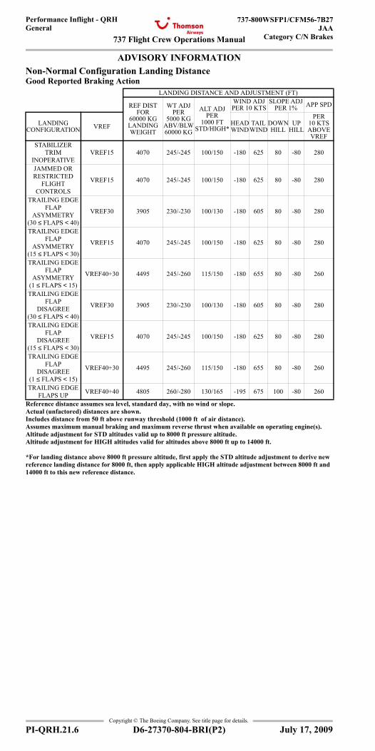
737 Flight Crew Operations Manual
Performance Inflight - QRHGeneral
737-800WSFP1/CFM56-7B27JAA
Category C/N Brakes
Copyright © The Boeing Company. See title page for details.
PI-QRH.21.6 D6-27370-804-BRI(P2)
ADVISORY INFORMATIONAdvisory Information
Non-Normal Configuration Landing DistanceGood Reported Braking Action
LANDING DISTANCE AND ADJUSTMENT (FT)
REF DIST FOR
60000 KG LANDING WEIGHT
WT ADJ PER
5000 KG ABV/BLW 60000 KG
ALT ADJ PER
1000 FT STD/HIGH*
WIND ADJ PER 10 KTS
SLOPE ADJ PER 1% APP SPD
LANDING CONFIGURATION VREF HEAD
WINDTAIL
WINDDOWN HILL
UP HILL
PER 10 KTS ABOVE VREF
STABILIZER TRIM
INOPERATIVEVREF15 4070 245/-245 100/150 -180 625 80 -80 280
JAMMED ORRESTRICTED
FLIGHTCONTROLS
VREF15 4070 245/-245 100/150 -180 625 80 -80 280
TRAILING EDGE FLAP
ASYMMETRY (30 ≤ FLAPS < 40)
VREF30 3905 230/-230 100/130 -180 605 80 -80 280
TRAILING EDGE FLAP
ASYMMETRY (15 ≤ FLAPS < 30)
VREF15 4070 245/-245 100/150 -180 625 80 -80 280
TRAILING EDGE FLAP
ASYMMETRY (1 ≤ FLAPS < 15)
VREF40+30 4495 245/-260 115/150 -180 655 80 -80 260
TRAILING EDGE FLAP
DISAGREE (30 ≤ FLAPS < 40)
VREF30 3905 230/-230 100/130 -180 605 80 -80 280
TRAILING EDGE FLAP
DISAGREE (15 ≤ FLAPS < 30)
VREF15 4070 245/-245 100/150 -180 625 80 -80 280
TRAILING EDGE FLAP
DISAGREE (1 ≤ FLAPS < 15)
VREF40+30 4495 245/-260 115/150 -180 655 80 -80 260
TRAILING EDGE FLAPS UP VREF40+40 4805 260/-280 130/165 -195 675 100 -80 260
Reference distance assumes sea level, standard day, with no wind or slope.Actual (unfactored) distances are shown.Includes distance from 50 ft above runway threshold (1000 ft of air distance).Assumes maximum manual braking and maximum reverse thrust when available on operating engine(s).Altitude adjustment for STD altitudes valid up to 8000 ft pressure altitude.Altitude adjustment for HIGH altitudes valid for altitudes above 8000 ft up to 14000 ft.
*For landing distance above 8000 ft pressure altitude, first apply the STD altitude adjustment to derive new reference landing distance for 8000 ft, then apply applicable HIGH altitude adjustment between 8000 ft and 14000 ft to this new reference distance.
July 17, 2009
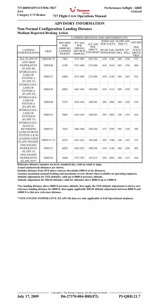
737 Flight Crew Operations Manual
Performance Inflight - QRHGeneral
737-800WSFP1/CFM56-7B27JAACategory C/N Brakes
Copyright © The Boeing Company. See title page for details.
D6-27370-804-BRI(P2) PI-QRH.21.7
ADVISORY INFORMATIONAdvisory Information
Non-Normal Configuration Landing DistanceMedium Reported Braking Action
LANDING DISTANCE AND ADJUSTMENT (FT)
REF DIST FOR
60000 KG LANDING WEIGHT
WT ADJ PER
5000 KG ABV/BLW 60000 KG
ALT ADJ PER
1000 FT STD/HIGH*
WIND ADJ PER 10 KTS
SLOPE ADJ PER 1% APP SPD
LANDING CONFIGURATION VREF HEAD
WINDTAIL
WINDDOWN HILL
UP HILL
PER 10 KTS ABOVE VREF
ALL FLAPS UP VREF40+55 7465 475/-490 245/330 -330 1180 260 -230 375ANTI SKID
INOPERATIVE (FLAPS 40)
VREF40 6740 475/-490 215/280 -410 1610 445 -330 460
HYDRAULICS - LOSS OF
SYSTEM A (FLAPS 15)
VREF15 6480 475/-490 215/280 -330 1150 295 -245 525
HYDRAULICS - LOSS OF
SYSTEM A (FLAPS 30)
VREF30 6085 445/-445 195/260 -310 1115 280 -230 510
HYDRAULICS - LOSS OF
SYSTEM A (FLAPS 40)
VREF40 5725 410/-410 180/245 -295 1085 260 -230 510
HYDRAULICS - LOSS OF
SYSTEM B (FLAPS 15)
VREF15 5805 410/-410 180/245 -295 1065 230 -195 410
HYDRAULICS - MANUAL
REVERSION (LOSS OF BOTH SYSTEM A & B)
VREF15 7810 540/-540 245/330 -375 1295 395 -330 705
LEADING EDGE FLAPS TRANSIT VREF15+15 6235 425/-425 195/260 -295 1100 230 -195 375
ONE ENGINE INOPERATIVE
(FLAPS 15)VREF15 6020 410/-425 180/230 -310 1130 260 -230 425
ONE ENGINE INOPERATIVE (FLAPS 30)**
VREF30 5660 375/-395 165/215 -295 1085 260 -215 410
Reference distance assumes sea level, standard day, with no wind or slope.Actual (unfactored) distances are shown.Includes distance from 50 ft above runway threshold (1000 ft of air distance).Assumes maximum manual braking and maximum reverse thrust when available on operating engine(s).Altitude adjustment for STD altitudes valid up to 8000 ft pressure altitude.Altitude adjustment for HIGH altitudes valid for altitudes above 8000 ft up to 14000 ft.
*For landing distance above 8000 ft pressure altitude, first apply the STD altitude adjustment to derive new reference landing distance for 8000 ft, then apply applicable HIGH altitude adjustment between 8000 ft and 14000 ft to this new reference distance.
**ONE ENGINE INOPERATIVE (FLAPS 30) data are only applicable to Fail Operational airplanes.
July 17, 2009

737 Flight Crew Operations Manual
Performance Inflight - QRHGeneral
737-800WSFP1/CFM56-7B27JAA
Category C/N Brakes
Copyright © The Boeing Company. See title page for details.
PI-QRH.21.8 D6-27370-804-BRI(P2)
ADVISORY INFORMATIONAdvisory Information
Non-Normal Configuration Landing DistanceMedium Reported Braking Action
LANDING DISTANCE AND ADJUSTMENT (FT)
REF DIST FOR
60000 KG LANDING WEIGHT
WT ADJ PER
5000 KG ABV/BLW 60000 KG
ALT ADJ PER
1000 FT STD/HIGH*
WIND ADJ PER 10 KTS
SLOPE ADJ PER 1% APP SPD
LANDING CONFIGURATION VREF HEAD
WINDTAIL
WINDDOWN HILL
UP HILL
PER 10 KTS ABOVE VREF
STABILIZER TRIM
INOPERATIVEVREF15 5545 375/-395 165/230 -280 1035 215 -180 375
JAMMED ORRESTRICTIVE
FLIGHTCONTROLS
VREF15 5545 375/-395 165/230 -280 1035 215 -180 375
TRAILING EDGE FLAP
ASYMMETRY (30 ≤ FLAPS < 40)
VREF30 5250 360/-360 150/195 -280 1015 195 -180 360
TRAILING EDGE FLAP
ASYMMETRY (15 ≤ FLAPS < 30)
VREF15 5545 375/-395 165/230 -280 1035 215 -180 375
TRAILING EDGE FLAP
ASYMMETRY (1 ≤ FLAPS < 15)
VREF40+30 6185 395/-410 195/260 -295 1085 230 -195 360
TRAILING EDGE FLAP
DISAGREE (30 ≤ FLAPS < 40)
VREF30 5250 360/-360 150/195 -280 1015 195 -180 360
TRAILING EDGE FLAP
DISAGREE (15 ≤ FLAPS < 30)
VREF15 5545 375/-395 165/230 -280 1035 215 -180 375
TRAILING EDGE FLAP
DISAGREE (1 ≤ FLAPS < 15)
VREF40+30 6185 395/-410 195/260 -295 1085 230 -195 360
TRAILING EDGE FLAPS UP VREF40+40 6695 425/-445 215/280 -310 1130 245 -215 375
Reference distance assumes sea level, standard day, with no wind or slope.Actual (unfactored) distances are shown.Includes distance from 50 ft above runway threshold (1000 ft of air distance).Assumes maximum manual braking and maximum reverse thrust when available on operating engine(s).Altitude adjustment for STD altitudes valid up to 8000 ft pressure altitude.Altitude adjustment for HIGH altitudes valid for altitudes above 8000 ft up to 14000 ft.
*For landing distance above 8000 ft pressure altitude, first apply the STD altitude adjustment to derive new reference landing distance for 8000 ft, then apply applicable HIGH altitude adjustment between 8000 ft and 14000 ft to this new reference distance.
July 17, 2009

737 Flight Crew Operations Manual
Performance Inflight - QRHGeneral
737-800WSFP1/CFM56-7B27JAACategory C/N Brakes
Copyright © The Boeing Company. See title page for details.
D6-27370-804-BRI(P2) PI-QRH.21.9
ADVISORY INFORMATIONAdvisory Information
Non-Normal Configuration Landing DistancePoor Reported Braking Action
LANDING DISTANCE AND ADJUSTMENT (FT)
REF DIST FOR
60000 KG LANDING WEIGHT
WT ADJ PER
5000 KG ABV/BLW 60000 KG
ALT ADJ PER
1000 FT STD/HIGH*
WIND ADJ PER 10 KTS
SLOPE ADJ PER 1% APP SPD
LANDING CONFIGURATION VREF HEAD
WINDTAIL
WINDDOWN HILL
UP HILL
PER 10 KTS ABOVE VREF
ALL FLAPS UP VREF40+55 9890 705/-720 360/475 -490 1870 625 -475 475ANTI SKID
INOPERATIVE (FLAPS 40)
VREF40 8940 705/-690 295/445 -675 2955 1575 -770 510
HYDRAULICS - LOSS OF
SYSTEM A (FLAPS 15)
VREF15 8385 690/-675 310/425 -475 1790 640 -475 625
HYDRAULICS - LOSS OF
SYSTEM A (FLAPS 30)
VREF30 7790 625/-605 280/375 -460 1740 590 -445 575
HYDRAULICS - LOSS OF
SYSTEM A (FLAPS 40)
VREF40 7315 575/-575 245/345 -445 1705 575 -425 560
HYDRAULICS - LOSS OF
SYSTEM B (FLAPS 15)
VREF15 7545 590/-575 260/360 -445 1690 525 -395 490
HYDRAULICS - MANUAL
REVERSION (LOSS OF BOTH SYSTEM A & B)
VREF15 10025 770/-755 345/490 -540 1970 785 -605 785
LEADING EDGE FLAPS TRANSIT VREF15+15 8040 605/-605 280/375 -445 1705 525 -395 445
ONE ENGINE INOPERATIVE
(FLAPS 15)VREF15 8220 625/-625 260/360 -490 1835 675 -490 525
ONE ENGINE INOPERATIVE (FLAPS 30)**
VREF30 7610 560/-575 245/330 -460 1770 625 -460 490
Reference distance assumes sea level, standard day, with no wind or slope.Actual (unfactored) distances are shown.Includes distance from 50 ft above runway threshold (1000 ft of air distance).Assumes maximum manual braking and maximum reverse thrust when available on operating engine(s).Altitude adjustment for STD altitudes valid up to 8000 ft pressure altitude.Altitude adjustment for HIGH altitudes valid for altitudes above 8000 ft up to 14000 ft.
*For landing distance above 8000 ft pressure altitude, first apply the STD altitude adjustment to derive new reference landing distance for 8000 ft, then apply applicable HIGH altitude adjustment between 8000 ft and 14000 ft to this new reference distance.
**ONE ENGINE INOPERATIVE (FLAPS 30) data are only applicable to Fail Operational airplanes.
July 17, 2009
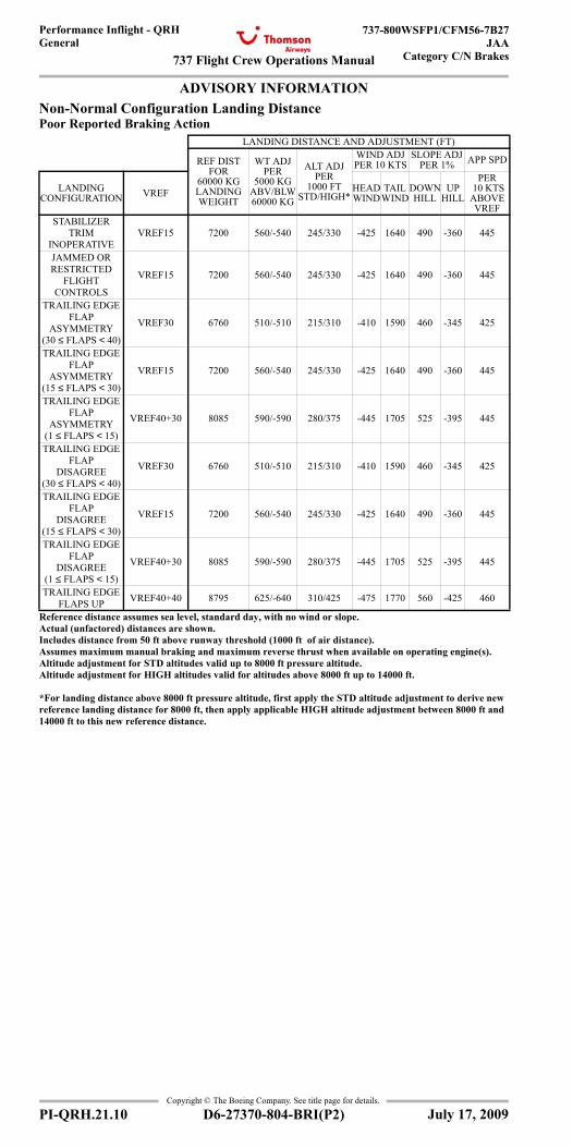
737 Flight Crew Operations Manual
Performance Inflight - QRHGeneral
737-800WSFP1/CFM56-7B27JAA
Category C/N Brakes
Copyright © The Boeing Company. See title page for details.
PI-QRH.21.10 D6-27370-804-BRI(P2)
ADVISORY INFORMATIONAdvisory Information
Non-Normal Configuration Landing DistancePoor Reported Braking Action
LANDING DISTANCE AND ADJUSTMENT (FT)
REF DIST FOR
60000 KG LANDING WEIGHT
WT ADJ PER
5000 KG ABV/BLW 60000 KG
ALT ADJ PER
1000 FT STD/HIGH*
WIND ADJ PER 10 KTS
SLOPE ADJ PER 1% APP SPD
LANDING CONFIGURATION VREF HEAD
WINDTAIL
WINDDOWN HILL
UP HILL
PER 10 KTS ABOVE VREF
STABILIZER TRIM
INOPERATIVEVREF15 7200 560/-540 245/330 -425 1640 490 -360 445
JAMMED ORRESTRICTED
FLIGHTCONTROLS
VREF15 7200 560/-540 245/330 -425 1640 490 -360 445
TRAILING EDGE FLAP
ASYMMETRY (30 ≤ FLAPS < 40)
VREF30 6760 510/-510 215/310 -410 1590 460 -345 425
TRAILING EDGE FLAP
ASYMMETRY (15 ≤ FLAPS < 30)
VREF15 7200 560/-540 245/330 -425 1640 490 -360 445
TRAILING EDGE FLAP
ASYMMETRY (1 ≤ FLAPS < 15)
VREF40+30 8085 590/-590 280/375 -445 1705 525 -395 445
TRAILING EDGE FLAP
DISAGREE (30 ≤ FLAPS < 40)
VREF30 6760 510/-510 215/310 -410 1590 460 -345 425
TRAILING EDGE FLAP
DISAGREE (15 ≤ FLAPS < 30)
VREF15 7200 560/-540 245/330 -425 1640 490 -360 445
TRAILING EDGE FLAP
DISAGREE (1 ≤ FLAPS < 15)
VREF40+30 8085 590/-590 280/375 -445 1705 525 -395 445
TRAILING EDGE FLAPS UP VREF40+40 8795 625/-640 310/425 -475 1770 560 -425 460
Reference distance assumes sea level, standard day, with no wind or slope.Actual (unfactored) distances are shown.Includes distance from 50 ft above runway threshold (1000 ft of air distance).Assumes maximum manual braking and maximum reverse thrust when available on operating engine(s).Altitude adjustment for STD altitudes valid up to 8000 ft pressure altitude.Altitude adjustment for HIGH altitudes valid for altitudes above 8000 ft up to 14000 ft.
*For landing distance above 8000 ft pressure altitude, first apply the STD altitude adjustment to derive new reference landing distance for 8000 ft, then apply applicable HIGH altitude adjustment between 8000 ft and 14000 ft to this new reference distance.
July 17, 2009
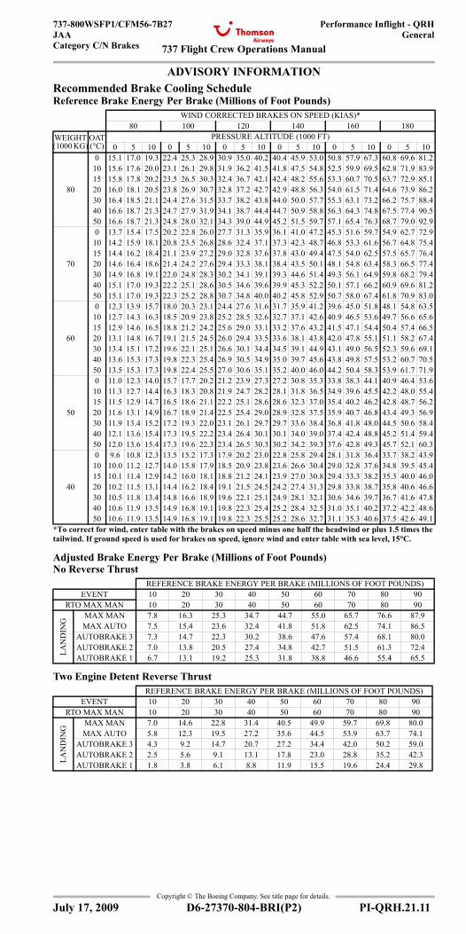
737 Flight Crew Operations Manual
Performance Inflight - QRHGeneral
737-800WSFP1/CFM56-7B27JAACategory C/N Brakes
Copyright © The Boeing Company. See title page for details.
D6-27370-804-BRI(P2) PI-QRH.21.11
ADVISORY INFORMATIONRecommended Brake Cooling Schedule Reference Brake Energy Per Brake (Millions of Foot Pounds)
Adjusted Brake Energy Per Brake (Millions of Foot Pounds)No Reverse Thrust
Two Engine Detent Reverse Thrust
WIND CORRECTED BRAKES ON SPEED (KIAS)*80 100 120 140 160 180
WEIGHT (1000 KG)
OAT (°C)
PRESSURE ALTITUDE (1000 FT)0 5 10 0 5 10 0 5 10 0 5 10 0 5 10 0 5 10
80
0 15.1 17.0 19.3 22.4 25.3 28.9 30.9 35.0 40.2 40.4 45.9 53.0 50.8 57.9 67.3 60.8 69.6 81.210 15.6 17.6 20.0 23.1 26.1 29.8 31.9 36.2 41.5 41.8 47.5 54.8 52.5 59.9 69.5 62.8 71.9 83.915 15.8 17.8 20.2 23.5 26.5 30.3 32.4 36.7 42.1 42.4 48.2 55.6 53.3 60.7 70.5 63.7 72.9 85.120 16.0 18.1 20.5 23.8 26.9 30.7 32.8 37.2 42.7 42.9 48.8 56.3 54.0 61.5 71.4 64.6 73.9 86.230 16.4 18.5 21.1 24.4 27.6 31.5 33.7 38.2 43.8 44.0 50.0 57.7 55.3 63.1 73.2 66.2 75.7 88.440 16.6 18.7 21.3 24.7 27.9 31.9 34.1 38.7 44.4 44.7 50.9 58.8 56.3 64.3 74.8 67.5 77.4 90.550 16.6 18.7 21.3 24.8 28.0 32.1 34.3 39.0 44.9 45.2 51.5 59.7 57.1 65.4 76.3 68.7 79.0 92.9
70
0 13.7 15.4 17.5 20.2 22.8 26.0 27.7 31.3 35.9 36.1 41.0 47.2 45.3 51.6 59.7 54.9 62.7 72.910 14.2 15.9 18.1 20.8 23.5 26.8 28.6 32.4 37.1 37.3 42.3 48.7 46.8 53.3 61.6 56.7 64.8 75.415 14.4 16.2 18.4 21.1 23.9 27.2 29.0 32.8 37.6 37.8 43.0 49.4 47.5 54.0 62.5 57.5 65.7 76.420 14.6 16.4 18.6 21.4 24.2 27.6 29.4 33.3 38.1 38.4 43.5 50.1 48.1 54.8 63.4 58.3 66.5 77.430 14.9 16.8 19.1 22.0 24.8 28.3 30.2 34.1 39.1 39.3 44.6 51.4 49.3 56.1 64.9 59.8 68.2 79.440 15.1 17.0 19.3 22.2 25.1 28.6 30.5 34.6 39.6 39.9 45.3 52.2 50.1 57.1 66.2 60.9 69.6 81.250 15.1 17.0 19.3 22.3 25.2 28.8 30.7 34.8 40.0 40.2 45.8 52.9 50.7 58.0 67.4 61.8 70.9 83.0
60
0 12.3 13.9 15.7 18.0 20.3 23.1 24.4 27.6 31.6 31.7 35.9 41.2 39.6 45.0 51.8 48.1 54.8 63.510 12.7 14.3 16.3 18.5 20.9 23.8 25.2 28.5 32.6 32.7 37.1 42.6 40.9 46.5 53.6 49.7 56.6 65.615 12.9 14.6 16.5 18.8 21.2 24.2 25.6 29.0 33.1 33.2 37.6 43.2 41.5 47.1 54.4 50.4 57.4 66.520 13.1 14.8 16.7 19.1 21.5 24.5 26.0 29.4 33.5 33.6 38.1 43.8 42.0 47.8 55.1 51.1 58.2 67.430 13.4 15.1 17.2 19.6 22.1 25.1 26.6 30.1 34.4 34.5 39.1 44.9 43.1 49.0 56.5 52.3 59.6 69.140 13.6 15.3 17.3 19.8 22.3 25.4 26.9 30.5 34.9 35.0 39.7 45.6 43.8 49.8 57.5 53.2 60.7 70.550 13.5 15.3 17.3 19.8 22.4 25.5 27.0 30.6 35.1 35.2 40.0 46.0 44.2 50.4 58.3 53.9 61.7 71.9
50
0 11.0 12.3 14.0 15.7 17.7 20.2 21.2 23.9 27.3 27.2 30.8 35.3 33.8 38.3 44.1 40.9 46.4 53.610 11.3 12.7 14.4 16.3 18.3 20.8 21.9 24.7 28.2 28.1 31.8 36.5 34.9 39.6 45.5 42.2 48.0 55.415 11.5 12.9 14.7 16.5 18.6 21.1 22.2 25.1 28.6 28.6 32.3 37.0 35.4 40.2 46.2 42.8 48.7 56.220 11.6 13.1 14.9 16.7 18.9 21.4 22.5 25.4 29.0 28.9 32.8 37.5 35.9 40.7 46.8 43.4 49.3 56.930 11.9 13.4 15.2 17.2 19.3 22.0 23.1 26.1 29.7 29.7 33.6 38.4 36.8 41.8 48.0 44.5 50.6 58.440 12.1 13.6 15.4 17.3 19.5 22.2 23.4 26.4 30.1 30.1 34.0 39.0 37.4 42.4 48.8 45.2 51.4 59.450 12.0 13.6 15.4 17.3 19.6 22.3 23.4 26.5 30.3 30.2 34.2 39.3 37.6 42.8 49.3 45.7 52.1 60.3
40
0 9.6 10.8 12.3 13.5 15.2 17.3 17.9 20.2 23.0 22.8 25.8 29.4 28.1 31.8 36.4 33.7 38.2 43.910 10.0 11.2 12.7 14.0 15.8 17.9 18.5 20.9 23.8 23.6 26.6 30.4 29.0 32.8 37.6 34.8 39.5 45.415 10.1 11.4 12.9 14.2 16.0 18.1 18.8 21.2 24.1 23.9 27.0 30.8 29.4 33.3 38.2 35.3 40.0 46.020 10.2 11.5 13.1 14.4 16.2 18.4 19.1 21.5 24.5 24.2 27.4 31.3 29.8 33.8 38.7 35.8 40.6 46.630 10.5 11.8 13.4 14.8 16.6 18.9 19.6 22.1 25.1 24.9 28.1 32.1 30.6 34.6 39.7 36.7 41.6 47.840 10.6 11.9 13.5 14.9 16.8 19.1 19.8 22.3 25.4 25.2 28.4 32.5 31.0 35.1 40.2 37.2 42.2 48.650 10.6 11.9 13.5 14.9 16.8 19.1 19.8 22.3 25.5 25.2 28.6 32.7 31.1 35.3 40.6 37.5 42.6 49.1
*To correct for wind, enter table with the brakes on speed minus one half the headwind or plus 1.5 times the tailwind. If ground speed is used for brakes on speed, ignore wind and enter table with sea level, 15°C.
REFERENCE BRAKE ENERGY PER BRAKE (MILLIONS OF FOOT POUNDS)EVENT 10 20 30 40 50 60 70 80 90
RTO MAX MAN 10 20 30 40 50 60 70 80 90
LAN
DIN
G
MAX MAN 7.8 16.3 25.3 34.7 44.7 55.0 65.7 76.6 87.9MAX AUTO 7.5 15.4 23.6 32.4 41.8 51.8 62.5 74.1 86.5
AUTOBRAKE 3 7.3 14.7 22.3 30.2 38.6 47.6 57.4 68.1 80.0AUTOBRAKE 2 7.0 13.8 20.5 27.4 34.8 42.7 51.5 61.3 72.4AUTOBRAKE 1 6.7 13.1 19.2 25.3 31.8 38.8 46.6 55.4 65.5
REFERENCE BRAKE ENERGY PER BRAKE (MILLIONS OF FOOT POUNDS)EVENT 10 20 30 40 50 60 70 80 90
RTO MAX MAN 10 20 30 40 50 60 70 80 90
LAN
DIN
G
MAX MAN 7.0 14.6 22.8 31.4 40.5 49.9 59.7 69.8 80.0MAX AUTO 5.8 12.3 19.5 27.2 35.6 44.5 53.9 63.7 74.1
AUTOBRAKE 3 4.3 9.2 14.7 20.7 27.2 34.4 42.0 50.2 59.0AUTOBRAKE 2 2.5 5.6 9.1 13.1 17.8 23.0 28.8 35.2 42.3AUTOBRAKE 1 1.8 3.8 6.1 8.8 11.9 15.5 19.6 24.4 29.8
July 17, 2009
General
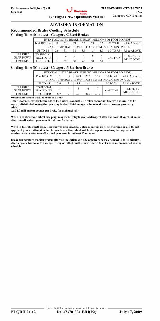
737 Flight Crew Operations Manual
Performance Inflight - QRHGeneral
737-800WSFP1/CFM56-7B27JAA
Category C/N Brakes
Copyright © The Boeing Company. See title page for details.
PI-QRH.21.12 D6-27370-804-BRI(P2)
ADVISORY INFORMATIONRecommended Brake Cooling Schedule Cooling Time (Minutes) - Category C Steel Brakes
Cooling Time (Minutes) - Category N Carbon Brakes
EVENT ADJUSTED BRAKE ENERGY (MILLIONS OF FOOT POUNDS)16 & BELOW 17 20 23 25 28 32 33 TO 48 49 & ABOVE
BRAKE TEMPERATURE MONITOR SYSTEM INDICATION ON CDSUP TO 2.4 2.6 3.1 3.5 3.9 4.4 4.9 5.0 TO 7.5 7.5 & ABOVE
INFLIGHT GEAR DOWN
NO SPECIAL PROCEDURE REQUIRED
1 2 3 4 5 6 CAUTION FUSE PLUG MELT ZONEGROUND 10 20 30 40 50 60
EVENT ADJUSTED BRAKE ENERGY (MILLIONS OF FOOT POUNDS)16 & BELOW 17 19 20.9 23.5 26.9 30 TO 41 41 & ABOVE
BRAKE TEMPERATURE MONITOR SYSTEM INDICATION ON CDSUP TO 2.5 2.6 3 3.3 3.8 4.5 5.0 TO 7.1 7.1 & ABOVE
INFLIGHT GEAR DOWN
NO SPECIAL PROCEDURE REQUIRED
1 4 5 6 7 CAUTION FUSE PLUG MELT ZONEGROUND 6.7 16.0 24.1 34.2 45.9
Observe maximum quick turnaround limit.Table shows energy per brake added by a single stop with all brakes operating. Energy is assumed to be equally distributed among the operating brakes. Total energy is the sum of residual energy plus energy added. Add 1.0 million foot pounds per brake for each taxi mile.
When in caution zone, wheel fuse plugs may melt. Delay takeoff and inspect after one hour. If overheat occurs after takeoff, extend gear soon for at least 7 minutes.
When in fuse plug melt zone, clear runway immediately. Unless required, do not set parking brake. Do not approach gear or attempt to taxi for one hour. Tire, wheel and brake replacement may be required. If overheat occurs after takeoff, extend gear soon for at least 12 minutes.
Brake temperature monitor system (BTMS) indication on CDS systems page may be used 10 to 15 minutes after airplane has come to a complete stop or inflight with gear retracted to determine recommended cooling schedule.
July 17, 2009
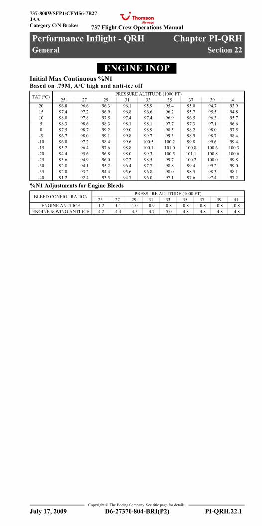
737 Flight Crew Operations Manual
Performance Inflight - QRH Chapter PI-QRHGeneral Section 22
737-800WSFP1/CFM56-7B27JAACategory C/N Brakes
Copyright © The Boeing Company. See title page for details.
D6-27370-804-BRI(P2) PI-QRH.22.1
PI-QRH.22 Performance Inflight - QRH-GeneralENGINE INOPEngine Inoperative
Initial Max Continuous %N1Based on .79M, A/C high and anti-ice off
%N1 Adjustments for Engine Bleeds
TAT (°C) PRESSURE ALTITUDE (1000 FT)25 27 29 31 33 35 37 39 41
20 96.8 96.6 96.3 96.1 95.9 95.4 95.0 94.7 93.915 97.4 97.2 96.9 96.8 96.6 96.2 95.7 95.5 94.810 98.0 97.8 97.5 97.4 97.4 96.9 96.5 96.3 95.75 98.3 98.6 98.3 98.1 98.1 97.7 97.3 97.1 96.60 97.5 98.7 99.2 99.0 98.9 98.5 98.2 98.0 97.5-5 96.7 98.0 99.1 99.8 99.7 99.3 98.9 98.7 98.4
-10 96.0 97.2 98.4 99.6 100.5 100.2 99.8 99.6 99.4-15 95.2 96.4 97.6 98.8 100.1 101.0 100.8 100.6 100.3-20 94.4 95.6 96.8 98.0 99.3 100.5 101.1 100.8 100.6-25 93.6 94.9 96.0 97.2 98.5 99.7 100.2 100.0 99.8-30 92.8 94.1 95.2 96.4 97.7 98.8 99.4 99.2 99.0-35 92.0 93.2 94.4 95.6 96.8 98.0 98.5 98.3 98.1-40 91.2 92.4 93.5 94.7 96.0 97.1 97.6 97.4 97.2
BLEED CONFIGURATION PRESSURE ALTITUDE (1000 FT)25 27 29 31 33 35 37 39 41
ENGINE ANTI-ICE -1.2 -1.1 -1.0 -0.9 -0.8 -0.8 -0.8 -0.8 -0.8ENGINE & WING ANTI-ICE -4.2 -4.4 -4.5 -4.7 -5.0 -4.8 -4.8 -4.8 -4.8
July 17, 2009
General
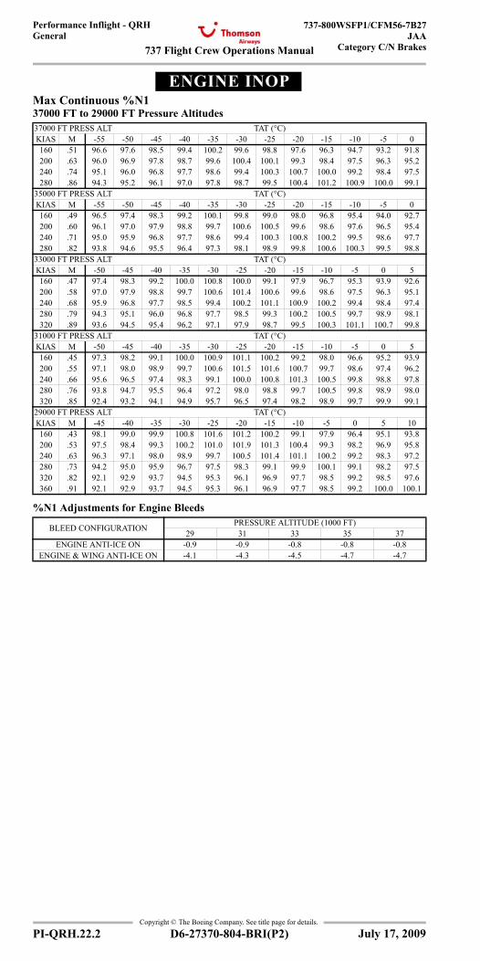
737 Flight Crew Operations Manual
Performance Inflight - QRHGeneral
737-800WSFP1/CFM56-7B27JAA
Category C/N Brakes
Copyright © The Boeing Company. See title page for details.
PI-QRH.22.2 D6-27370-804-BRI(P2)
ENGINE INOPEngine Inoperative
Max Continuous %N137000 FT to 29000 FT Pressure Altitudes
%N1 Adjustments for Engine Bleeds
37000 FT PRESS ALT TAT (°C)KIAS M -55 -50 -45 -40 -35 -30 -25 -20 -15 -10 -5 0160 .51 96.6 97.6 98.5 99.4 100.2 99.6 98.8 97.6 96.3 94.7 93.2 91.8200 .63 96.0 96.9 97.8 98.7 99.6 100.4 100.1 99.3 98.4 97.5 96.3 95.2240 .74 95.1 96.0 96.8 97.7 98.6 99.4 100.3 100.7 100.0 99.2 98.4 97.5280 .86 94.3 95.2 96.1 97.0 97.8 98.7 99.5 100.4 101.2 100.9 100.0 99.1
35000 FT PRESS ALT TAT (°C)KIAS M -55 -50 -45 -40 -35 -30 -25 -20 -15 -10 -5 0160 .49 96.5 97.4 98.3 99.2 100.1 99.8 99.0 98.0 96.8 95.4 94.0 92.7200 .60 96.1 97.0 97.9 98.8 99.7 100.6 100.5 99.6 98.6 97.6 96.5 95.4240 .71 95.0 95.9 96.8 97.7 98.6 99.4 100.3 100.8 100.2 99.5 98.6 97.7280 .82 93.8 94.6 95.5 96.4 97.3 98.1 98.9 99.8 100.6 100.3 99.5 98.8
33000 FT PRESS ALT TAT (°C)KIAS M -50 -45 -40 -35 -30 -25 -20 -15 -10 -5 0 5160 .47 97.4 98.3 99.2 100.0 100.8 100.0 99.1 97.9 96.7 95.3 93.9 92.6200 .58 97.0 97.9 98.8 99.7 100.6 101.4 100.6 99.6 98.6 97.5 96.3 95.1240 .68 95.9 96.8 97.7 98.5 99.4 100.2 101.1 100.9 100.2 99.4 98.4 97.4280 .79 94.3 95.1 96.0 96.8 97.7 98.5 99.3 100.2 100.5 99.7 98.9 98.1320 .89 93.6 94.5 95.4 96.2 97.1 97.9 98.7 99.5 100.3 101.1 100.7 99.8
31000 FT PRESS ALT TAT (°C)KIAS M -50 -45 -40 -35 -30 -25 -20 -15 -10 -5 0 5160 .45 97.3 98.2 99.1 100.0 100.9 101.1 100.2 99.2 98.0 96.6 95.2 93.9200 .55 97.1 98.0 98.9 99.7 100.6 101.5 101.6 100.7 99.7 98.6 97.4 96.2240 .66 95.6 96.5 97.4 98.3 99.1 100.0 100.8 101.3 100.5 99.8 98.8 97.8280 .76 93.8 94.7 95.5 96.4 97.2 98.0 98.8 99.7 100.5 99.8 98.9 98.0320 .85 92.4 93.2 94.1 94.9 95.7 96.5 97.4 98.2 98.9 99.7 99.9 99.1
29000 FT PRESS ALT TAT (°C)KIAS M -45 -40 -35 -30 -25 -20 -15 -10 -5 0 5 10160 .43 98.1 99.0 99.9 100.8 101.6 101.2 100.2 99.1 97.9 96.4 95.1 93.8200 .53 97.5 98.4 99.3 100.2 101.0 101.9 101.3 100.4 99.3 98.2 96.9 95.8240 .63 96.3 97.1 98.0 98.9 99.7 100.5 101.4 101.1 100.2 99.2 98.3 97.2280 .73 94.2 95.0 95.9 96.7 97.5 98.3 99.1 99.9 100.1 99.1 98.2 97.5320 .82 92.1 92.9 93.7 94.5 95.3 96.1 96.9 97.7 98.5 99.2 98.5 97.6360 .91 92.1 92.9 93.7 94.5 95.3 96.1 96.9 97.7 98.5 99.2 100.0 100.1
BLEED CONFIGURATION PRESSURE ALTITUDE (1000 FT)29 31 33 35 37
ENGINE ANTI-ICE ON -0.9 -0.9 -0.8 -0.8 -0.8ENGINE & WING ANTI-ICE ON -4.1 -4.3 -4.5 -4.7 -4.7
July 17, 2009
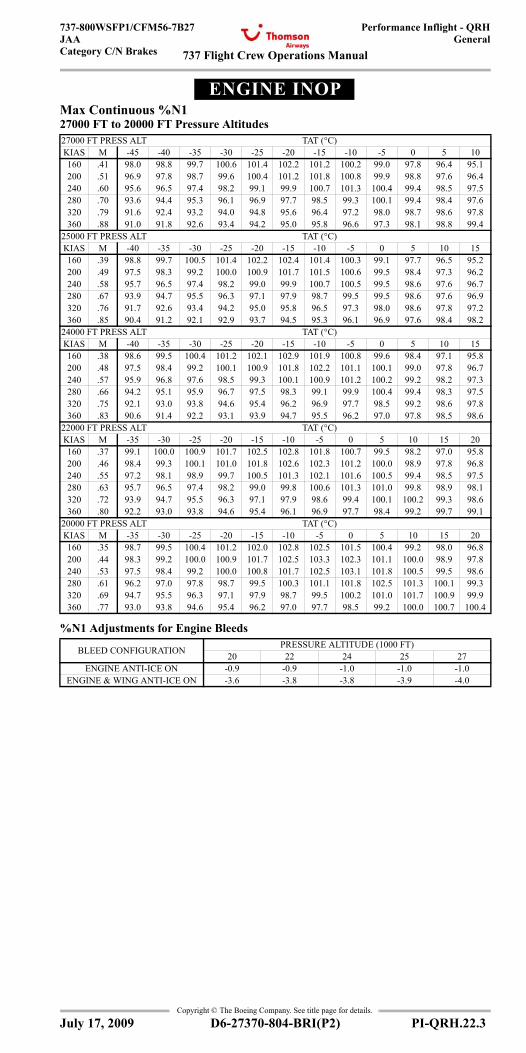
737 Flight Crew Operations Manual
Performance Inflight - QRHGeneral
737-800WSFP1/CFM56-7B27JAACategory C/N Brakes
Copyright © The Boeing Company. See title page for details.
D6-27370-804-BRI(P2) PI-QRH.22.3
ENGINE INOPEngine Inoperative
Max Continuous %N127000 FT to 20000 FT Pressure Altitudes
%N1 Adjustments for Engine Bleeds
27000 FT PRESS ALT TAT (°C)KIAS M -45 -40 -35 -30 -25 -20 -15 -10 -5 0 5 10160 .41 98.0 98.8 99.7 100.6 101.4 102.2 101.2 100.2 99.0 97.8 96.4 95.1200 .51 96.9 97.8 98.7 99.6 100.4 101.2 101.8 100.8 99.9 98.8 97.6 96.4240 .60 95.6 96.5 97.4 98.2 99.1 99.9 100.7 101.3 100.4 99.4 98.5 97.5280 .70 93.6 94.4 95.3 96.1 96.9 97.7 98.5 99.3 100.1 99.4 98.4 97.6320 .79 91.6 92.4 93.2 94.0 94.8 95.6 96.4 97.2 98.0 98.7 98.6 97.8360 .88 91.0 91.8 92.6 93.4 94.2 95.0 95.8 96.6 97.3 98.1 98.8 99.4
25000 FT PRESS ALT TAT (°C)KIAS M -40 -35 -30 -25 -20 -15 -10 -5 0 5 10 15160 .39 98.8 99.7 100.5 101.4 102.2 102.4 101.4 100.3 99.1 97.7 96.5 95.2200 .49 97.5 98.3 99.2 100.0 100.9 101.7 101.5 100.6 99.5 98.4 97.3 96.2240 .58 95.7 96.5 97.4 98.2 99.0 99.9 100.7 100.5 99.5 98.6 97.6 96.7280 .67 93.9 94.7 95.5 96.3 97.1 97.9 98.7 99.5 99.5 98.6 97.6 96.9320 .76 91.7 92.6 93.4 94.2 95.0 95.8 96.5 97.3 98.0 98.6 97.8 97.2360 .85 90.4 91.2 92.1 92.9 93.7 94.5 95.3 96.1 96.9 97.6 98.4 98.2
24000 FT PRESS ALT TAT (°C)KIAS M -40 -35 -30 -25 -20 -15 -10 -5 0 5 10 15160 .38 98.6 99.5 100.4 101.2 102.1 102.9 101.9 100.8 99.6 98.4 97.1 95.8200 .48 97.5 98.4 99.2 100.1 100.9 101.8 102.2 101.1 100.1 99.0 97.8 96.7240 .57 95.9 96.8 97.6 98.5 99.3 100.1 100.9 101.2 100.2 99.2 98.2 97.3280 .66 94.2 95.1 95.9 96.7 97.5 98.3 99.1 99.9 100.4 99.4 98.3 97.5320 .75 92.1 93.0 93.8 94.6 95.4 96.2 96.9 97.7 98.5 99.2 98.6 97.8360 .83 90.6 91.4 92.2 93.1 93.9 94.7 95.5 96.2 97.0 97.8 98.5 98.6
22000 FT PRESS ALT TAT (°C)KIAS M -35 -30 -25 -20 -15 -10 -5 0 5 10 15 20160 .37 99.1 100.0 100.9 101.7 102.5 102.8 101.8 100.7 99.5 98.2 97.0 95.8200 .46 98.4 99.3 100.1 101.0 101.8 102.6 102.3 101.2 100.0 98.9 97.8 96.8240 .55 97.2 98.1 98.9 99.7 100.5 101.3 102.1 101.6 100.5 99.4 98.5 97.5280 .63 95.7 96.5 97.4 98.2 99.0 99.8 100.6 101.3 101.0 99.8 98.9 98.1320 .72 93.9 94.7 95.5 96.3 97.1 97.9 98.6 99.4 100.1 100.2 99.3 98.6360 .80 92.2 93.0 93.8 94.6 95.4 96.1 96.9 97.7 98.4 99.2 99.7 99.1
20000 FT PRESS ALT TAT (°C)KIAS M -35 -30 -25 -20 -15 -10 -5 0 5 10 15 20160 .35 98.7 99.5 100.4 101.2 102.0 102.8 102.5 101.5 100.4 99.2 98.0 96.8200 .44 98.3 99.2 100.0 100.9 101.7 102.5 103.3 102.3 101.1 100.0 98.9 97.8240 .53 97.5 98.4 99.2 100.0 100.8 101.7 102.5 103.1 101.8 100.5 99.5 98.6280 .61 96.2 97.0 97.8 98.7 99.5 100.3 101.1 101.8 102.5 101.3 100.1 99.3320 .69 94.7 95.5 96.3 97.1 97.9 98.7 99.5 100.2 101.0 101.7 100.9 99.9360 .77 93.0 93.8 94.6 95.4 96.2 97.0 97.7 98.5 99.2 100.0 100.7 100.4
BLEED CONFIGURATION PRESSURE ALTITUDE (1000 FT)20 22 24 25 27
ENGINE ANTI-ICE ON -0.9 -0.9 -1.0 -1.0 -1.0ENGINE & WING ANTI-ICE ON -3.6 -3.8 -3.8 -3.9 -4.0
July 17, 2009
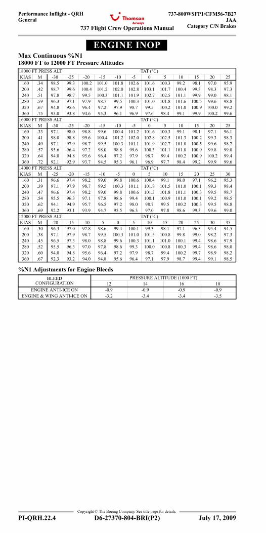
737 Flight Crew Operations Manual
Performance Inflight - QRHGeneral
737-800WSFP1/CFM56-7B27JAA
Category C/N Brakes
Copyright © The Boeing Company. See title page for details.
PI-QRH.22.4 D6-27370-804-BRI(P2)
ENGINE INOPEngine Inoperative
Max Continuous %N118000 FT to 12000 FT Pressure Altitudes
%N1 Adjustments for Engine Bleeds
18000 FT PRESS ALT TAT (°C)KIAS M -30 -25 -20 -15 -10 -5 0 5 10 15 20 25160 .34 98.5 99.3 100.2 101.0 101.8 102.6 101.6 100.3 99.2 98.1 97.0 95.9200 .42 98.7 99.6 100.4 101.2 102.0 102.8 103.1 101.7 100.4 99.3 98.3 97.3240 .51 97.8 98.7 99.5 100.3 101.1 101.9 102.7 102.5 101.1 99.9 99.0 98.1280 .59 96.3 97.1 97.9 98.7 99.5 100.3 101.0 101.8 101.6 100.5 99.6 98.8320 .67 94.8 95.6 96.4 97.2 97.9 98.7 99.5 100.2 101.0 100.9 100.0 99.2360 .75 93.0 93.8 94.6 95.3 96.1 96.9 97.6 98.4 99.1 99.9 100.2 99.6
16000 FT PRESS ALT TAT (°C)KIAS M -30 -25 -20 -15 -10 -5 0 5 10 15 20 25160 .33 97.1 98.0 98.8 99.6 100.4 101.2 101.6 100.3 99.1 98.1 97.1 96.1200 .41 98.0 98.8 99.6 100.4 101.2 102.0 102.8 102.5 101.3 100.2 99.3 98.3240 .49 97.1 97.9 98.7 99.5 100.3 101.1 101.9 102.7 101.8 100.5 99.6 98.7280 .57 95.6 96.4 97.2 98.0 98.8 99.6 100.3 101.1 101.8 100.9 99.8 99.0320 .64 94.0 94.8 95.6 96.4 97.2 97.9 98.7 99.4 100.2 100.9 100.2 99.4360 .72 92.1 92.9 93.7 94.5 95.3 96.1 96.9 97.7 98.4 99.2 99.9 99.6
14000 FT PRESS ALT TAT (°C)KIAS M -25 -20 -15 -10 -5 0 5 10 15 20 25 30160 .31 96.6 97.4 98.2 99.0 99.8 100.6 100.4 99.1 98.0 97.1 96.2 95.3200 .39 97.1 97.9 98.7 99.5 100.3 101.1 101.8 101.5 101.0 100.1 99.3 98.4240 .47 96.6 97.4 98.2 99.0 99.8 100.6 101.3 101.8 101.1 100.3 99.5 98.7280 .54 95.5 96.3 97.1 97.8 98.6 99.4 100.1 100.9 101.0 100.1 99.2 98.5320 .62 94.1 94.9 95.7 96.5 97.2 98.0 98.7 99.5 100.2 100.3 99.5 98.8360 .69 92.2 93.1 93.9 94.7 95.5 96.3 97.0 97.8 98.6 99.3 99.6 99.0
12000 FT PRESS ALT TAT (°C)KIAS M -20 -15 -10 -5 0 5 10 15 20 25 30 35160 .30 96.3 97.0 97.8 98.6 99.4 100.1 99.3 98.1 97.1 96.3 95.4 94.5200 .38 97.1 97.9 98.7 99.5 100.3 101.0 101.5 100.8 99.8 99.0 98.2 97.3240 .45 96.5 97.3 98.0 98.8 99.6 100.3 101.1 101.0 100.1 99.4 98.6 97.9280 .52 95.5 96.3 97.0 97.8 98.6 99.3 100.0 100.8 100.3 99.4 98.6 98.0320 .60 94.0 94.8 95.6 96.4 97.2 97.9 98.7 99.4 100.2 99.7 98.9 98.2360 .67 92.3 93.2 94.0 94.8 95.6 96.4 97.1 97.9 98.7 99.4 99.1 98.5
BLEED CONFIGURATION
PRESSURE ALTITUDE (1000 FT)12 14 16 18
ENGINE ANTI-ICE ON -0.9 -0.9 -0.9 -0.9ENGINE & WING ANTI-ICE ON -3.2 -3.4 -3.4 -3.5
July 17, 2009
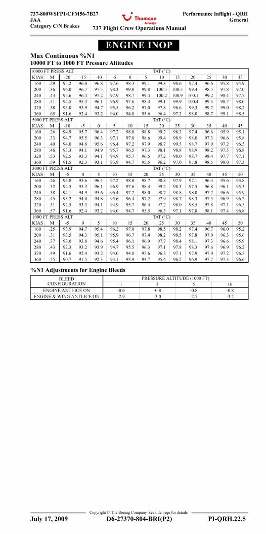
737 Flight Crew Operations Manual
Performance Inflight - QRHGeneral
737-800WSFP1/CFM56-7B27JAACategory C/N Brakes
Copyright © The Boeing Company. See title page for details.
D6-27370-804-BRI(P2) PI-QRH.22.5
ENGINE INOPEngine Inoperative
Max Continuous %N110000 FT to 1000 FT Pressure Altitudes
%N1 Adjustments for Engine Bleeds
10000 FT PRESS ALT TAT (°C)KIAS M -20 -15 -10 -5 0 5 10 15 20 25 30 35160 .29 95.2 96.0 96.8 97.6 98.3 99.1 99.8 98.6 97.4 96.6 95.8 94.9200 .36 96.0 96.7 97.5 98.3 99.0 99.8 100.5 100.5 99.4 98.5 97.8 97.0240 .43 95.6 96.4 97.2 97.9 98.7 99.4 100.2 100.9 100.1 99.2 98.4 97.7280 .51 94.5 95.3 96.1 96.9 97.6 98.4 99.1 99.9 100.4 99.5 98.7 98.0320 .58 93.0 93.9 94.7 95.5 96.2 97.0 97.8 98.6 99.3 99.7 99.0 98.2360 .65 91.6 92.4 93.2 94.0 94.8 95.6 96.4 97.2 98.0 98.7 99.1 98.5
5000 FT PRESS ALT TAT (°C)KIAS M -10 -5 0 5 10 15 20 25 30 35 40 45160 .26 94.9 95.7 96.4 97.2 98.0 98.8 99.2 98.3 97.4 96.6 95.9 95.1200 .33 94.7 95.5 96.3 97.1 97.8 98.6 99.4 98.9 98.0 97.3 96.6 95.8240 .40 94.0 94.8 95.6 96.4 97.2 97.9 98.7 99.5 98.7 97.9 97.2 96.5280 .46 93.3 94.1 94.9 95.7 96.5 97.3 98.1 98.8 98.9 98.2 97.5 96.8320 .53 92.5 93.3 94.1 94.9 95.7 96.5 97.2 98.0 98.7 98.4 97.7 97.1360 .59 91.5 92.3 93.1 93.9 94.7 95.5 96.2 97.0 97.8 98.5 98.0 97.3
3000 FT PRESS ALT TAT (°C)KIAS M -5 0 5 10 15 20 25 30 35 40 45 50160 .26 94.8 95.6 96.4 97.2 98.0 98.7 98.8 97.9 97.1 96.4 95.6 94.8200 .32 94.5 95.3 96.1 96.9 97.6 98.4 99.2 98.3 97.5 96.8 96.1 95.3240 .38 94.1 94.9 95.6 96.4 97.2 98.0 98.7 98.8 98.0 97.2 96.6 95.9280 .45 93.2 94.0 94.8 95.6 96.4 97.2 97.9 98.7 98.3 97.5 96.9 96.2320 .51 92.5 93.3 94.1 94.9 95.7 96.4 97.2 98.0 98.5 97.8 97.1 96.5360 .57 91.6 92.4 93.2 94.0 94.7 95.5 96.3 97.1 97.8 98.1 97.4 96.8
1000 FT PRESS ALT TAT (°C)KIAS M -5 0 5 10 15 20 25 30 35 40 45 50160 .25 93.9 94.7 95.4 96.2 97.0 97.8 98.5 98.2 97.4 96.7 96.0 95.2200 .31 93.5 94.3 95.1 95.9 96.7 97.4 98.2 98.5 97.8 97.0 96.3 95.6240 .37 93.0 93.8 94.6 95.4 96.1 96.9 97.7 98.4 98.1 97.3 96.6 95.9280 .43 92.3 93.2 93.9 94.7 95.5 96.3 97.1 97.8 98.3 97.6 96.9 96.2320 .49 91.6 92.4 93.2 94.0 94.8 95.6 96.3 97.1 97.9 97.9 97.2 96.5360 .55 90.7 91.5 92.3 93.1 93.9 94.7 95.4 96.2 96.9 97.7 97.3 96.6
BLEED CONFIGURATION
PRESSURE ALTITUDE (1000 FT)1 3 5 10
ENGINE ANTI-ICE ON -0.6 -0.8 -0.8 -0.8ENGINE & WING ANTI-ICE ON -2.9 -3.0 -2.7 -3.2
July 17, 2009
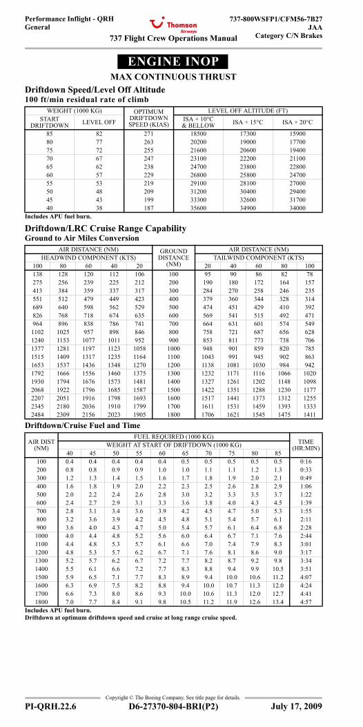
737 Flight Crew Operations Manual
Performance Inflight - QRHGeneral
737-800WSFP1/CFM56-7B27JAA
Category C/N Brakes
Copyright © The Boeing Company. See title page for details.
PI-QRH.22.6 D6-27370-804-BRI(P2)
ENGINE INOPMAX CONTINUOUS THRUST
Driftdown Speed/Level Off Altitude100 ft/min residual rate of climb
Driftdown/LRC Cruise Range CapabilityGround to Air Miles Conversion
Driftdown/Cruise Fuel and Time
WEIGHT (1000 KG) OPTIMUM DRIFTDOWN SPEED (KIAS)
LEVEL OFF ALTITUDE (FT)START
DRIFTDOWN LEVEL OFF ISA + 10°C & BELLOW ISA + 15°C ISA + 20°C
85 82 271 18500 17300 1590080 77 263 20200 19000 1770075 72 255 21600 20600 1940070 67 247 23100 22200 2110065 62 238 24700 23800 2280060 57 229 26800 25800 2470055 53 219 29100 28100 2700050 48 209 31200 30400 2940045 43 199 33300 32600 3170040 38 187 35600 34900 34000
Includes APU fuel burn.
AIR DISTANCE (NM) GROUND DISTANCE
(NM)
AIR DISTANCE (NM)HEADWIND COMPONENT (KTS) TAILWIND COMPONENT (KTS)
100 80 60 40 20 20 40 60 80 100138 128 120 112 106 100 95 90 86 82 78275 256 239 225 212 200 190 180 172 164 157413 384 359 337 317 300 284 270 258 246 235551 512 479 449 423 400 379 360 344 328 314689 640 598 562 529 500 474 451 429 410 392826 768 718 674 635 600 569 541 515 492 471964 896 838 786 741 700 664 631 601 574 5491102 1025 957 898 846 800 758 721 687 656 6281240 1153 1077 1011 952 900 853 811 773 738 7061377 1281 1197 1123 1058 1000 948 901 859 820 7851515 1409 1317 1235 1164 1100 1043 991 945 902 8631653 1537 1436 1348 1270 1200 1138 1081 1030 984 9421792 1666 1556 1460 1375 1300 1232 1171 1116 1066 10201930 1794 1676 1573 1481 1400 1327 1261 1202 1148 10982068 1922 1796 1685 1587 1500 1422 1351 1288 1230 11772207 2051 1916 1798 1693 1600 1517 1441 1373 1312 12552345 2180 2036 1910 1799 1700 1611 1531 1459 1393 13332484 2309 2156 2023 1905 1800 1706 1621 1545 1475 1411
AIR DIST (NM)
FUEL REQUIRED (1000 KG)TIME
(HR:MIN)WEIGHT AT START OF DRIFTDOWN (1000 KG)40 45 50 55 60 65 70 75 80 85
100 0.4 0.4 0.4 0.4 0.4 0.5 0.5 0.5 0.5 0.5 0:16200 0.8 0.8 0.9 0.9 1.0 1.0 1.1 1.1 1.2 1.3 0:33300 1.2 1.3 1.4 1.5 1.6 1.7 1.8 1.9 2.0 2.1 0:49400 1.6 1.8 1.9 2.0 2.2 2.3 2.5 2.6 2.8 2.9 1:06500 2.0 2.2 2.4 2.6 2.8 3.0 3.2 3.3 3.5 3.7 1:22600 2.4 2.7 2.9 3.1 3.3 3.6 3.8 4.0 4.3 4.5 1:39700 2.8 3.1 3.4 3.6 3.9 4.2 4.5 4.7 5.0 5.3 1:55800 3.2 3.6 3.9 4.2 4.5 4.8 5.1 5.4 5.7 6.1 2:11900 3.6 4.0 4.3 4.7 5.0 5.4 5.7 6.1 6.4 6.8 2:28
1000 4.0 4.4 4.8 5.2 5.6 6.0 6.4 6.7 7.1 7.6 2:441100 4.4 4.8 5.3 5.7 6.1 6.6 7.0 7.4 7.9 8.3 3:011200 4.8 5.3 5.7 6.2 6.7 7.1 7.6 8.1 8.6 9.0 3:171300 5.2 5.7 6.2 6.7 7.2 7.7 8.2 8.7 9.2 9.8 3:341400 5.5 6.1 6.6 7.2 7.7 8.3 8.8 9.4 9.9 10.5 3:511500 5.9 6.5 7.1 7.7 8.3 8.9 9.4 10.0 10.6 11.2 4:071600 6.3 6.9 7.5 8.2 8.8 9.4 10.0 10.7 11.3 12.0 4:241700 6.6 7.3 8.0 8.6 9.3 10.0 10.6 11.3 12.0 12.7 4:411800 7.0 7.7 8.4 9.1 9.8 10.5 11.2 11.9 12.6 13.4 4:57
Includes APU fuel burn. Driftdown at optimum driftdown speed and cruise at long range cruise speed.
July 17, 2009
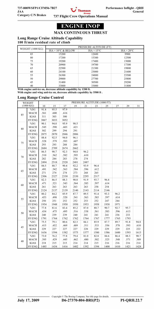
737 Flight Crew Operations Manual
Performance Inflight - QRHGeneral
737-800WSFP1/CFM56-7B27JAACategory C/N Brakes
Copyright © The Boeing Company. See title page for details.
D6-27370-804-BRI(P2) PI-QRH.22.7
ENGINE INOPMAX CONTINUOUS THRUST
Long Range Cruise Altitude Capability100 ft/min residual rate of climb
Long Range Cruise Control
WEIGHT (1000 KG) PRESSURE ALTITUDE (FT)ISA + 10°C & BELOW ISA + 15°C ISA + 20°C
85 15200 12600 990080 17200 15300 1250075 19200 17400 1500070 20900 19700 1730065 22500 21300 1980060 24100 23000 2160055 26300 24800 2350050 29000 27700 2580045 31400 30500 2920040 33800 33000 31800
With engine anti-ice on, decrease altitude capability by 1200 ft.With engine and wing anti-ice on, decrease altitude capability by 5500 ft .
WEIGHT (1000 KG)
PRESSURE ALTITUDE (1000 FT)10 15 17 19 21 23 25 27 29 31
85
%N1 91.8 95.5 97.9MACH .561 .600 .616KIAS 311 303 300
FF/ENG 3067 3033 3052
80
%N1 90.1 94.0 95.9 98.5MACH .545 .590 .603 .621KIAS 302 299 294 291
FF/ENG 2875 2870 2846 2886
75
%N1 88.4 92.5 94.0 96.1MACH .528 .579 .593 .607KIAS 293 293 288 284
FF/ENG 2684 2709 2674 2662
70
%N1 86.5 90.7 92.3 94.0 96.2MACH .510 .562 .582 .595 .610KIAS 282 284 283 278 274
FF/ENG 2494 2518 2520 2481 2487
65
%N1 84.5 88.7 90.4 92.2 93.9 96.4MACH .491 .542 .563 .584 .596 .612KIAS 271 274 274 273 268 265
FF/ENG 2306 2327 2330 2330 2295 2317
60
%N1 82.3 86.5 88.3 90.0 91.9 93.7 96.4MACH .471 .521 .543 .564 .585 .597 .614KIAS 261 263 263 263 263 258 254
FF/ENG 2124 2137 2139 2140 2143 2114 2146
55
%N1 80.2 84.2 85.9 87.7 89.5 91.4 93.3 96.2MACH .453 .498 .520 .541 .563 .585 .597 .614KIAS 250 251 252 252 253 252 247 244
FF/ENG 1954 1948 1950 1950 1953 1958 1938 1971
50
%N1 77.8 81.6 83.4 85.2 87.0 88.7 90.7 92.7 95.7MACH .434 .475 .495 .516 .538 .561 .583 .596 .613KIAS 240 239 239 240 241 241 241 236 233
FF/ENG 1791 1764 1762 1762 1764 1767 1777 1765 1793
45
%N1 75.5 79.1 80.6 82.3 84.1 85.9 87.7 89.7 91.8 94.8MACH .415 .452 .469 .489 .511 .533 .556 .578 .593 .610KIAS 229 227 227 227 228 229 229 229 225 222
FF/ENG 1636 1594 1582 1575 1577 1580 1586 1600 1593 1613
40
%N1 73.0 76.2 77.8 79.4 81.0 82.8 84.6 86.4 88.3 90.7MACH .395 .429 .445 .462 .480 .502 .525 .548 .571 .589KIAS 218 215 215 214 214 215 216 216 216 214
FF/ENG 1485 1434 1416 1402 1392 1394 1400 1410 1421 1424
July 17, 2009
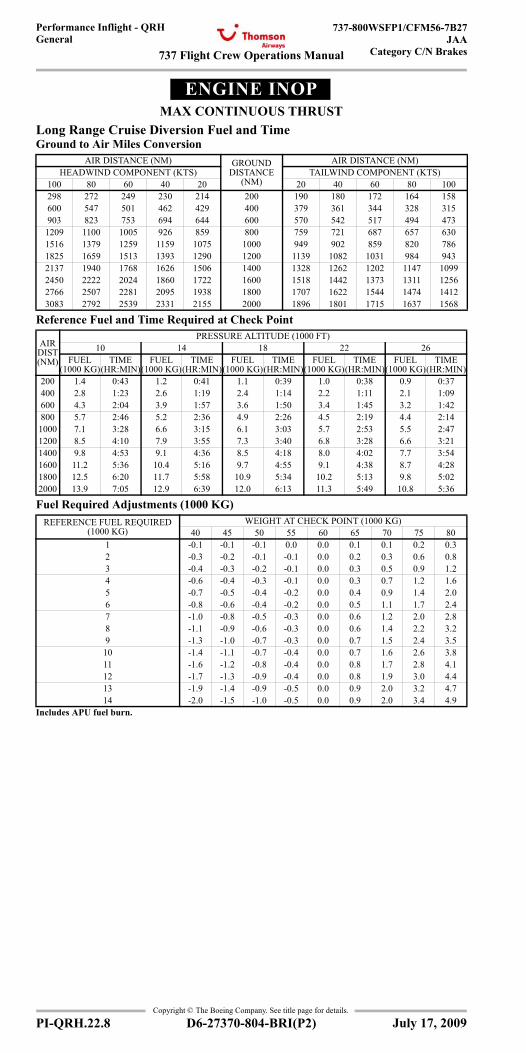
737 Flight Crew Operations Manual
Performance Inflight - QRHGeneral
737-800WSFP1/CFM56-7B27JAA
Category C/N Brakes
Copyright © The Boeing Company. See title page for details.
PI-QRH.22.8 D6-27370-804-BRI(P2)
ENGINE INOPMAX CONTINUOUS THRUST
Long Range Cruise Diversion Fuel and TimeGround to Air Miles Conversion
Reference Fuel and Time Required at Check Point
Fuel Required Adjustments (1000 KG)
AIR DISTANCE (NM) GROUND DISTANCE
(NM)
AIR DISTANCE (NM)HEADWIND COMPONENT (KTS) TAILWIND COMPONENT (KTS)
100 80 60 40 20 20 40 60 80 100298 272 249 230 214 200 190 180 172 164 158600 547 501 462 429 400 379 361 344 328 315903 823 753 694 644 600 570 542 517 494 473
1209 1100 1005 926 859 800 759 721 687 657 6301516 1379 1259 1159 1075 1000 949 902 859 820 7861825 1659 1513 1393 1290 1200 1139 1082 1031 984 9432137 1940 1768 1626 1506 1400 1328 1262 1202 1147 10992450 2222 2024 1860 1722 1600 1518 1442 1373 1311 12562766 2507 2281 2095 1938 1800 1707 1622 1544 1474 14123083 2792 2539 2331 2155 2000 1896 1801 1715 1637 1568
AIR DIST (NM)
PRESSURE ALTITUDE (1000 FT)10 14 18 22 26
FUEL (1000 KG)
TIME (HR:MIN)
FUEL (1000 KG)
TIME (HR:MIN)
FUEL (1000 KG)
TIME (HR:MIN)
FUEL (1000 KG)
TIME (HR:MIN)
FUEL (1000 KG)
TIME (HR:MIN)
200 1.4 0:43 1.2 0:41 1.1 0:39 1.0 0:38 0.9 0:37400 2.8 1:23 2.6 1:19 2.4 1:14 2.2 1:11 2.1 1:09600 4.3 2:04 3.9 1:57 3.6 1:50 3.4 1:45 3.2 1:42800 5.7 2:46 5.2 2:36 4.9 2:26 4.5 2:19 4.4 2:141000 7.1 3:28 6.6 3:15 6.1 3:03 5.7 2:53 5.5 2:471200 8.5 4:10 7.9 3:55 7.3 3:40 6.8 3:28 6.6 3:211400 9.8 4:53 9.1 4:36 8.5 4:18 8.0 4:02 7.7 3:541600 11.2 5:36 10.4 5:16 9.7 4:55 9.1 4:38 8.7 4:281800 12.5 6:20 11.7 5:58 10.9 5:34 10.2 5:13 9.8 5:022000 13.9 7:05 12.9 6:39 12.0 6:13 11.3 5:49 10.8 5:36
REFERENCE FUEL REQUIRED (1000 KG)
WEIGHT AT CHECK POINT (1000 KG)40 45 50 55 60 65 70 75 80
1 -0.1 -0.1 -0.1 0.0 0.0 0.1 0.1 0.2 0.32 -0.3 -0.2 -0.1 -0.1 0.0 0.2 0.3 0.6 0.83 -0.4 -0.3 -0.2 -0.1 0.0 0.3 0.5 0.9 1.24 -0.6 -0.4 -0.3 -0.1 0.0 0.3 0.7 1.2 1.65 -0.7 -0.5 -0.4 -0.2 0.0 0.4 0.9 1.4 2.06 -0.8 -0.6 -0.4 -0.2 0.0 0.5 1.1 1.7 2.47 -1.0 -0.8 -0.5 -0.3 0.0 0.6 1.2 2.0 2.88 -1.1 -0.9 -0.6 -0.3 0.0 0.6 1.4 2.2 3.29 -1.3 -1.0 -0.7 -0.3 0.0 0.7 1.5 2.4 3.510 -1.4 -1.1 -0.7 -0.4 0.0 0.7 1.6 2.6 3.811 -1.6 -1.2 -0.8 -0.4 0.0 0.8 1.7 2.8 4.112 -1.7 -1.3 -0.9 -0.4 0.0 0.8 1.9 3.0 4.413 -1.9 -1.4 -0.9 -0.5 0.0 0.9 2.0 3.2 4.714 -2.0 -1.5 -1.0 -0.5 0.0 0.9 2.0 3.4 4.9
Includes APU fuel burn.
July 17, 2009
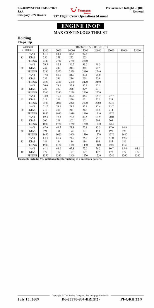
737 Flight Crew Operations Manual
Performance Inflight - QRHGeneral
737-800WSFP1/CFM56-7B27JAACategory C/N Brakes
Copyright © The Boeing Company. See title page for details.
D6-27370-804-BRI(P2) PI-QRH.22.9
ENGINE INOPMAX CONTINUOUS THRUST
HoldingFlaps Up
WEIGHT (1000 KG)
PRESSURE ALTITUDE (FT) 1500 5000 10000 15000 20000 25000 30000 35000
%N1 81.1 84.1 88.3 92.8 85 KIAS 250 251 252 253
FF/ENG 2740 2730 2750 2800 %N1 79.5 82.4 86.5 91.0 98.3
80 KIAS 242 243 244 245 247 FF/ENG 2580 2570 2570 2610 2740
%N1 77.8 80.5 84.7 89.1 95.0 75 KIAS 235 236 236 238 239
FF/ENG 2420 2400 2400 2420 2490 %N1 76.0 78.6 82.8 87.1 92.1
70 KIAS 227 227 228 229 231 FF/ENG 2260 2240 2230 2250 2270
%N1 74.0 76.7 80.8 85.0 89.7 97.7 65 KIAS 219 219 220 221 222 224
FF/ENG 2100 2090 2070 2070 2080 2230 %N1 71.7 74.6 78.5 82.8 87.4 93.7
60 KIAS 210 210 211 212 213 214 FF/ENG 1950 1930 1910 1910 1910 1970
%N1 69.4 72.3 76.3 80.5 84.9 90.0 55 KIAS 200 201 202 203 204 205
FF/ENG 1800 1770 1750 1740 1730 1760 %N1 67.0 69.7 73.8 77.8 82.3 87.0 94.9
50 KIAS 191 191 192 193 194 195 196 FF/ENG 1650 1620 1600 1580 1570 1570 1680
%N1 64.3 66.9 71.0 75.0 79.4 84.0 89.6 45 KIAS 184 184 184 184 184 185 186
FF/ENG 1500 1470 1440 1430 1400 1400 1450 %N1 61.1 64.0 67.8 72.0 76.2 80.7 85.4 94.1
40 KIAS 177 177 177 177 177 177 177 177 FF/ENG 1350 1330 1300 1270 1250 1240 1260 1360
This table includes 5% additional fuel for holding in a racetrack pattern.
July 17, 2009
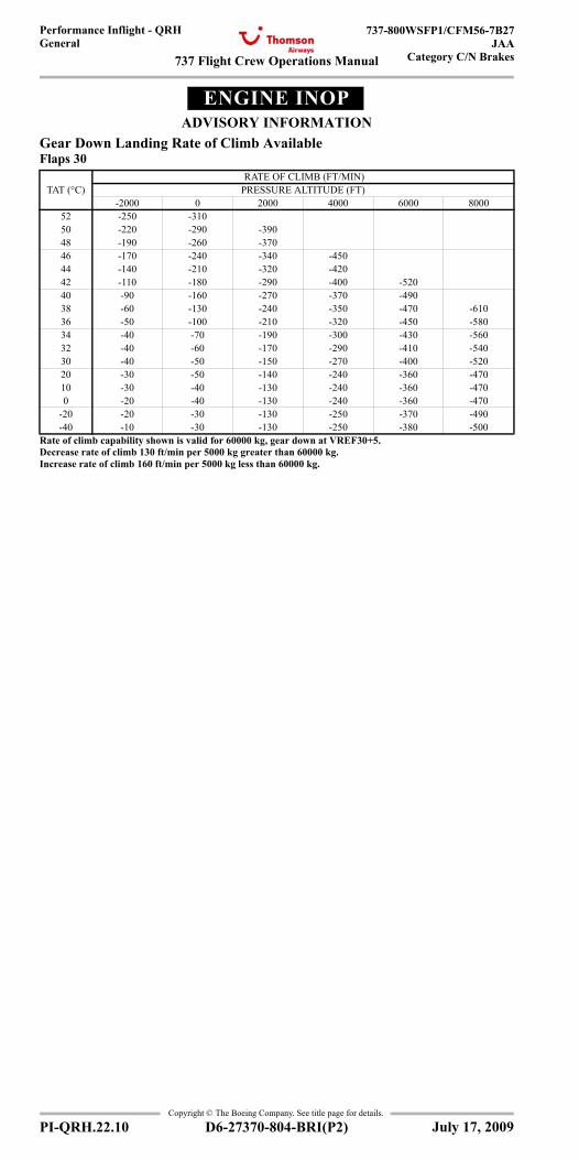
737 Flight Crew Operations Manual
Performance Inflight - QRHGeneral
737-800WSFP1/CFM56-7B27JAA
Category C/N Brakes
Copyright © The Boeing Company. See title page for details.
PI-QRH.22.10 D6-27370-804-BRI(P2)
ENGINE INOPADVISORY INFORMATION
Gear Down Landing Rate of Climb AvailableFlaps 30
TAT (°C) RATE OF CLIMB (FT/MIN) PRESSURE ALTITUDE (FT)
-2000 0 2000 4000 6000 800052 -250 -31050 -220 -290 -39048 -190 -260 -37046 -170 -240 -340 -45044 -140 -210 -320 -42042 -110 -180 -290 -400 -52040 -90 -160 -270 -370 -49038 -60 -130 -240 -350 -470 -61036 -50 -100 -210 -320 -450 -58034 -40 -70 -190 -300 -430 -56032 -40 -60 -170 -290 -410 -54030 -40 -50 -150 -270 -400 -52020 -30 -50 -140 -240 -360 -47010 -30 -40 -130 -240 -360 -4700 -20 -40 -130 -240 -360 -470
-20 -20 -30 -130 -250 -370 -490-40 -10 -30 -130 -250 -380 -500
Rate of climb capability shown is valid for 60000 kg, gear down at VREF30+5.Decrease rate of climb 130 ft/min per 5000 kg greater than 60000 kg.Increase rate of climb 160 ft/min per 5000 kg less than 60000 kg.
July 17, 2009
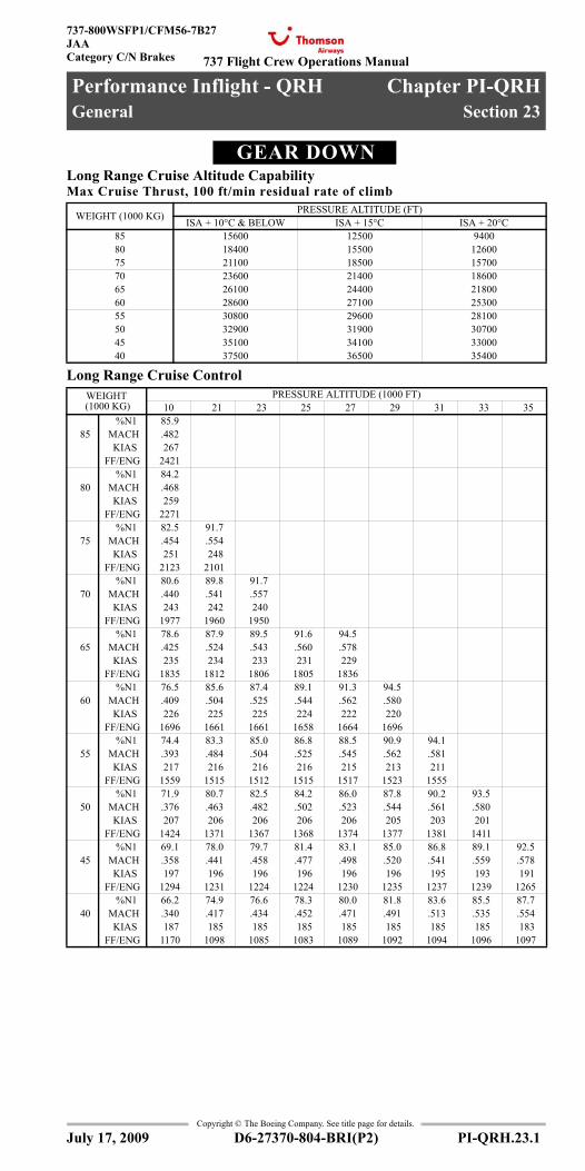
737 Flight Crew Operations Manual
Performance Inflight - QRH Chapter PI-QRHGeneral Section 23
737-800WSFP1/CFM56-7B27JAACategory C/N Brakes
Copyright © The Boeing Company. See title page for details.
D6-27370-804-BRI(P2) PI-QRH.23.1
PI-QRH.23 Performance Inflight - QRH-GeneralGEAR DOWNGear Down
Long Range Cruise Altitude CapabilityMax Cruise Thrust, 100 ft/min residual rate of climb
Long Range Cruise Control
WEIGHT (1000 KG) PRESSURE ALTITUDE (FT)ISA + 10°C & BELOW ISA + 15°C ISA + 20°C
85 15600 12500 940080 18400 15500 1260075 21100 18500 1570070 23600 21400 1860065 26100 24400 2180060 28600 27100 2530055 30800 29600 2810050 32900 31900 3070045 35100 34100 3300040 37500 36500 35400
WEIGHT (1000 KG)
PRESSURE ALTITUDE (1000 FT)10 21 23 25 27 29 31 33 35
%N1 85.9 85 MACH .482
KIAS 267 FF/ENG 2421 %N1 84.2
80 MACH .468 KIAS 259
FF/ENG 2271 %N1 82.5 91.7
75 MACH .454 .554 KIAS 251 248
FF/ENG 2123 2101 %N1 80.6 89.8 91.7
70 MACH .440 .541 .557 KIAS 243 242 240
FF/ENG 1977 1960 1950 %N1 78.6 87.9 89.5 91.6 94.5
65 MACH .425 .524 .543 .560 .578 KIAS 235 234 233 231 229
FF/ENG 1835 1812 1806 1805 1836 %N1 76.5 85.6 87.4 89.1 91.3 94.5
60 MACH .409 .504 .525 .544 .562 .580 KIAS 226 225 225 224 222 220
FF/ENG 1696 1661 1661 1658 1664 1696 %N1 74.4 83.3 85.0 86.8 88.5 90.9 94.1
55 MACH .393 .484 .504 .525 .545 .562 .581 KIAS 217 216 216 216 215 213 211
FF/ENG 1559 1515 1512 1515 1517 1523 1555 %N1 71.9 80.7 82.5 84.2 86.0 87.8 90.2 93.5
50 MACH .376 .463 .482 .502 .523 .544 .561 .580 KIAS 207 206 206 206 206 205 203 201
FF/ENG 1424 1371 1367 1368 1374 1377 1381 1411 %N1 69.1 78.0 79.7 81.4 83.1 85.0 86.8 89.1 92.5
45 MACH .358 .441 .458 .477 .498 .520 .541 .559 .578 KIAS 197 196 196 196 196 196 195 193 191
FF/ENG 1294 1231 1224 1224 1230 1235 1237 1239 1265 %N1 66.2 74.9 76.6 78.3 80.0 81.8 83.6 85.5 87.7
40 MACH .340 .417 .434 .452 .471 .491 .513 .535 .554 KIAS 187 185 185 185 185 185 185 185 183
FF/ENG 1170 1098 1085 1083 1089 1092 1094 1096 1097
July 17, 2009
General
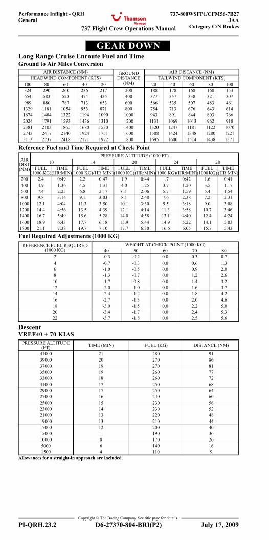
737 Flight Crew Operations Manual
Performance Inflight - QRHGeneral
737-800WSFP1/CFM56-7B27JAA
Category C/N Brakes
Copyright © The Boeing Company. See title page for details.
PI-QRH.23.2 D6-27370-804-BRI(P2)
GEAR DOWNGear Down
Long Range Cruise Enroute Fuel and TimeGround to Air Miles Conversion
Reference Fuel and Time Required at Check Point
Fuel Required Adjustments (1000 KG)
DescentVREF40 + 70 KIAS
AIR DISTANCE (NM) GROUND DISTANCE
(NM)
AIR DISTANCE (NM)HEADWIND COMPONENT (KTS) TAILWIND COMPONENT (KTS)
100 80 60 40 20 20 40 60 80 100324 290 260 236 217 200 188 178 168 160 153654 583 523 474 435 400 377 357 338 321 307989 880 787 713 653 600 566 535 507 483 461
1329 1181 1054 953 871 800 754 713 676 643 6141674 1484 1322 1194 1090 1000 943 891 844 803 7662024 1791 1593 1436 1310 1200 1131 1069 1013 962 9182381 2103 1865 1680 1530 1400 1320 1247 1181 1122 10702743 2417 2140 1924 1751 1600 1508 1424 1348 1280 12213113 2737 2418 2171 1972 1800 1695 1600 1514 1438 1371
AIR DIST (NM)
PRESSURE ALTITUDE (1000 FT)10 14 20 24 28
FUEL (1000 KG)
TIME (HR:MIN)
FUEL (1000 KG)
TIME (HR:MIN)
FUEL (1000 KG)
TIME (HR:MIN)
FUEL (1000 KG)
TIME (HR:MIN)
FUEL (1000 KG)
TIME (HR:MIN)
200 2.4 0:49 2.2 0:47 1.9 0:44 1.7 0:42 1.6 0:41400 4.9 1:36 4.5 1:31 4.0 1:25 3.7 1:20 3.5 1:17600 7.4 2:25 6.8 2:17 6.1 2:06 5.7 1:59 5.4 1:54800 9.8 3:14 9.1 3:03 8.1 2:48 7.6 2:38 7.2 2:311000 12.1 4:04 11.3 3:50 10.1 3:30 9.5 3:18 9.0 3:081200 14.4 4:56 13.5 4:39 12.1 4:14 11.3 3:58 10.7 3:461400 16.7 5:49 15.6 5:28 14.0 4:58 13.1 4:40 12.4 4:241600 18.9 6:43 17.7 6:18 15.9 5:44 14.9 5:22 14.1 5:031800 21.1 7:38 19.7 7:10 17.7 6:30 16.6 6:05 15.7 5:43
REFERENCE FUEL REQUIRED (1000 KG)
WEIGHT AT CHECK POINT (1000 KG)40 50 60 70 80
2 -0.3 -0.2 0.0 0.3 0.74 -0.7 -0.3 0.0 0.6 1.36 -1.0 -0.5 0.0 0.9 2.08 -1.3 -0.7 0.0 1.2 2.610 -1.7 -0.8 0.0 1.4 3.212 -2.0 -1.0 0.0 1.6 3.714 -2.4 -1.2 0.0 1.8 4.216 -2.7 -1.3 0.0 2.0 4.618 -3.0 -1.5 0.0 2.2 5.020 -3.4 -1.7 0.0 2.4 5.322 -3.7 -1.8 0.0 2.5 5.6
PRESSURE ALTITUDE (FT) TIME (MIN) FUEL (KG) DISTANCE (NM)
41000 21 280 9139000 20 270 8637000 19 270 8135000 19 260 7733000 18 260 7231000 17 250 6829000 17 250 6427000 16 240 6025000 15 230 5623000 14 230 5221000 13 220 4819000 13 210 4417000 12 200 4015000 11 190 3610000 8 170 265000 6 140 161500 4 110 9
Allowances for a straight-in approach are included.
July 17, 2009
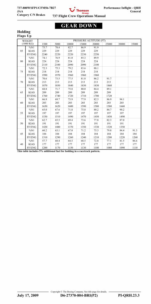
737 Flight Crew Operations Manual
Performance Inflight - QRHGeneral
737-800WSFP1/CFM56-7B27JAACategory C/N Brakes
Copyright © The Boeing Company. See title page for details.
D6-27370-804-BRI(P2) PI-QRH.23.3
GEAR DOWNGear Down
HoldingFlaps Up
WEIGHT (1000 KG)
PRESSURE ALTITUDE (FT) 1500 5000 10000 15000 20000 25000 30000 35000
%N1 75.7 78.4 82.7 86.9 91.9 85 KIAS 229 229 229 229 229
FF/ENG 2240 2220 2220 2230 2250 %N1 74.1 76.9 81.0 85.3 89.9
80 KIAS 224 224 224 224 224 FF/ENG 2110 2100 2090 2090 2100
%N1 72.3 75.3 79.2 83.6 88.1 75 KIAS 218 218 218 218 218
FF/ENG 1990 1970 1960 1960 1960 %N1 70.6 73.5 77.5 81.8 86.2 91.7
70 KIAS 213 213 213 213 213 213 FF/ENG 1870 1850 1840 1830 1830 1860
%N1 68.8 71.7 75.8 80.0 84.4 89.1 65 KIAS 209 209 209 209 209 209
FF/ENG 1760 1740 1720 1710 1700 1720 %N1 66.9 69.7 73.9 77.9 82.3 86.9 94.1
60 KIAS 203 203 203 203 203 203 203 FF/ENG 1650 1620 1600 1590 1580 1580 1660
%N1 65.0 67.6 71.8 75.8 80.2 84.7 90.2 55 KIAS 197 197 197 197 197 197 197
FF/ENG 1530 1510 1490 1470 1450 1450 1490 %N1 62.7 65.5 69.4 73.6 77.8 82.3 87.0
50 KIAS 191 191 191 191 191 191 191 FF/ENG 1420 1400 1370 1350 1330 1320 1350
%N1 60.2 63.1 67.0 71.2 75.3 79.8 84.4 91.3 45 KIAS 184 184 184 184 184 184 184 184
FF/ENG 1310 1290 1260 1240 1210 1200 1220 1260 %N1 57.7 60.4 64.5 68.5 72.8 77.1 81.5 86.6
40 KIAS 177 177 177 177 177 177 177 177 FF/ENG 1200 1170 1150 1130 1100 1080 1090 1110
This table includes 5% additional fuel for holding in a racetrack pattern.
July 17, 2009
737 Flight Crew Operations Manual
Performance Inflight - QRHGeneral
737-800WSFP1/CFM56-7B27JAA
Category C/N Brakes
Copyright © The Boeing Company. See title page for details.
PI-QRH.23.4 D6-27370-804-BRI(P2)
IntentionallyBlank
July 17, 2009
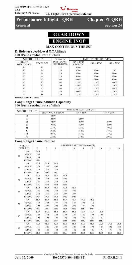
737 Flight Crew Operations Manual
Performance Inflight - QRH Chapter PI-QRHGeneral Section 24
737-800WSFP1/CFM56-7B27JAACategory C/N Brakes
Copyright © The Boeing Company. See title page for details.
D6-27370-804-BRI(P2) PI-QRH.24.1
PI-QRH.24 Performance Inflight - QRH-GeneralGEAR DOWNENGINE INOP
MAX CONTINUOUS THRUSTGear Down, Engine Inoperative
Driftdown Speed/Level Off Altitude100 ft/min residual rate of climb
Long Range Cruise Altitude Capability100 ft/min residual rate of climb
Long Range Cruise Control
WEIGHT (1000 KG) OPTIMUM DRIFTDOWN SPEED (KIAS)
LEVEL OFF ALTITUDE (FT)START
DRIFTDOWN LEVEL OFF ISA + 10°C & BELOW ISA + 15°C ISA + 20°C
85 80 227 170080 76 223 4000 2300 20075 71 218 6300 4900 280070 66 213 8600 7300 530065 62 208 10900 9800 800060 57 202 13200 12300 1090055 52 196 15600 14800 1390050 47 190 18100 17300 1650045 43 183 20600 19800 1890040 38 176 23100 22300 21400
Includes APU fuel burn.
WEIGHT (1000 KG) PRESSURE ALTITUDE (FT)ISA + 10°C & BELOW ISA + 15°C ISA + 20°C
75 150070 4500 250065 7500 5900 340060 10600 9200 690055 13300 12300 1060050 16200 15400 1450045 19300 18300 1750040 22200 21400 20500
WEIGHT (1000 KG)
PRESSURE ALTITUDE (1000 FT)5 7 9 11 13 15 17 19 21 23
70
%N1 94.8MACH .389KIAS 235
FF/ENG 3774
65
%N1 92.6 94.3 96.9MACH .376 .389 .402KIAS 228 227 226
FF/ENG 3477 3485 3527
60
%N1 90.2 91.9 93.7 96.3MACH .364 .375 .388 .402KIAS 220 219 218 218
FF/ENG 3192 3191 3198 3240
55
%N1 87.8 89.3 91.0 92.8 95.4MACH .351 .362 .374 .387 .400KIAS 212 211 210 209 209
FF/ENG 2924 2909 2906 2913 2951
50
%N1 85.3 86.7 88.2 89.9 91.7 94.2 98.2MACH .338 .348 .359 .371 .384 .398 .412KIAS 204 203 202 201 200 199 198
FF/ENG 2672 2647 2630 2626 2633 2657 2737
45
%N1 82.7 84.0 85.4 86.9 88.6 90.4 92.7 96.6MACH .325 .334 .344 .355 .367 .380 .393 .408KIAS 196 195 193 192 191 190 189 189
FF/ENG 2432 2400 2374 2356 2351 2352 2359 2417
40
%N1 79.8 81.1 82.5 83.9 85.4 87.0 88.8 90.8 94.1 98.4 MACH .311 .320 .329 .339 .349 .361 .374 .387 .402 .418 KIAS 188 186 184 183 182 181 180 179 179 178
FF/ENG 2206 2166 2133 2107 2088 2076 2069 2065 2101 2201
July 17, 2009
General
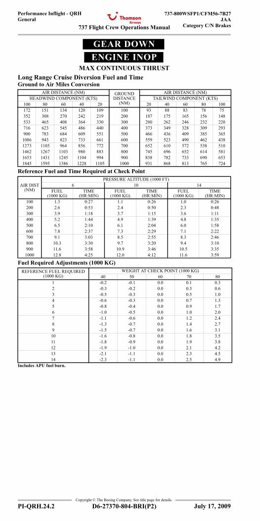
737 Flight Crew Operations Manual
Performance Inflight - QRHGeneral
737-800WSFP1/CFM56-7B27JAA
Category C/N Brakes
Copyright © The Boeing Company. See title page for details.
PI-QRH.24.2 D6-27370-804-BRI(P2)
GEAR DOWNENGINE INOP
MAX CONTINUOUS THRUSTGear Down, Engine Inoperative
Long Range Cruise Diversion Fuel and TimeGround to Air Miles Conversion
Reference Fuel and Time Required at Check Point
Fuel Required Adjustments (1000 KG)
AIR DISTANCE (NM) GROUND DISTANCE
(NM)
AIR DISTANCE (NM)HEADWIND COMPONENT (KTS) TAILWIND COMPONENT (KTS)
100 80 60 40 20 20 40 60 80 100172 151 134 120 109 100 93 88 83 78 75352 308 270 242 219 200 187 175 165 156 148533 465 408 364 330 300 280 262 246 232 220716 623 545 486 440 400 373 349 328 309 293900 783 684 609 551 500 466 436 409 385 365
1086 943 823 733 661 600 559 523 490 462 4381273 1105 964 856 772 700 652 610 572 538 5101462 1267 1103 980 883 800 745 696 652 614 5811653 1431 1245 1104 994 900 838 782 733 690 6531845 1595 1386 1228 1105 1000 931 868 813 765 724
AIR DIST (NM)
PRESSURE ALTITUDE (1000 FT)6 10 14
FUEL(1000 KG)
TIME(HR:MIN)
FUEL(1000 KG)
TIME (HR:MIN)
FUEL (1000 KG)
TIME(HR:MIN)
100 1.3 0:27 1.1 0:26 1.0 0:26200 2.6 0:53 2.4 0:50 2.3 0:48300 3.9 1:18 3.7 1:15 3.6 1:11400 5.2 1:44 4.9 1:39 4.8 1:35500 6.5 2:10 6.1 2:04 6.0 1:58600 7.8 2:37 7.3 2:29 7.1 2:22700 9.1 3:03 8.5 2:55 8.3 2:46800 10.3 3:30 9.7 3:20 9.4 3:10900 11.6 3:58 10.9 3:46 10.5 3:35
1000 12.8 4:25 12.0 4:12 11.6 3:59
REFERENCE FUEL REQUIRED (1000 KG)
WEIGHT AT CHECK POINT (1000 KG)40 50 60 70 80
1 -0.2 -0.1 0.0 0.1 0.32 -0.3 -0.2 0.0 0.3 0.63 -0.5 -0.3 0.0 0.5 1.04 -0.6 -0.3 0.0 0.7 1.35 -0.8 -0.4 0.0 0.9 1.76 -1.0 -0.5 0.0 1.0 2.07 -1.1 -0.6 0.0 1.2 2.48 -1.3 -0.7 0.0 1.4 2.79 -1.5 -0.7 0.0 1.6 3.110 -1.6 -0.8 0.0 1.8 3.511 -1.8 -0.9 0.0 1.9 3.812 -1.9 -1.0 0.0 2.1 4.213 -2.1 -1.1 0.0 2.3 4.514 -2.3 -1.1 0.0 2.5 4.9
Includes APU fuel burn.
July 17, 2009
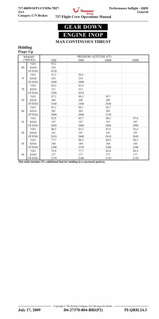
737 Flight Crew Operations Manual
Performance Inflight - QRHGeneral
737-800WSFP1/CFM56-7B27JAACategory C/N Brakes
Copyright © The Boeing Company. See title page for details.
D6-27370-804-BRI(P2) PI-QRH.24.3
GEAR DOWNENGINE INOP
MAX CONTINUOUS THRUSTGear Down, Engine Inoperative
HoldingFlaps Up
WEIGHT (1000 KG)
PRESSURE ALTITUDE (FT)1500 5000 10000 15000
%N1 93.2 80 KIAS 224
FF/ENG 4120 %N1 91.2 94.5
75 KIAS 218 218 FF/ENG 3840 3890
%N1 89.2 92.4 70 KIAS 213 213
FF/ENG 3580 3610 %N1 87.3 90.3 95.7
65 KIAS 209 209 209 FF/ENG 3340 3360 3430
%N1 85.1 88.1 92.7 60 KIAS 203 203 203
FF/ENG 3090 3090 3130 %N1 82.8 85.7 90.2 97.0
55 KIAS 197 197 197 197 FF/ENG 2850 2840 2860 2990
%N1 80.2 83.2 87.6 92.6 50 KIAS 191 191 191 191
FF/ENG 2610 2600 2610 2650 %N1 77.7 80.5 84.9 89.5
45 KIAS 184 184 184 184 FF/ENG 2390 2370 2360 2380
%N1 75.0 77.7 82.0 86.4 40 KIAS 177 177 177 177
FF/ENG 2170 2140 2120 2130 This table includes 5% additional fuel for holding in a racetrack pattern.
July 17, 2009

737 Flight Crew Operations Manual
Performance Inflight - QRHGeneral
737-800WSFP1/CFM56-7B27JAA
Category C/N Brakes
Copyright © The Boeing Company. See title page for details.
PI-QRH.24.4 D6-27370-804-BRI(P2)
IntentionallyBlank
July 17, 2009
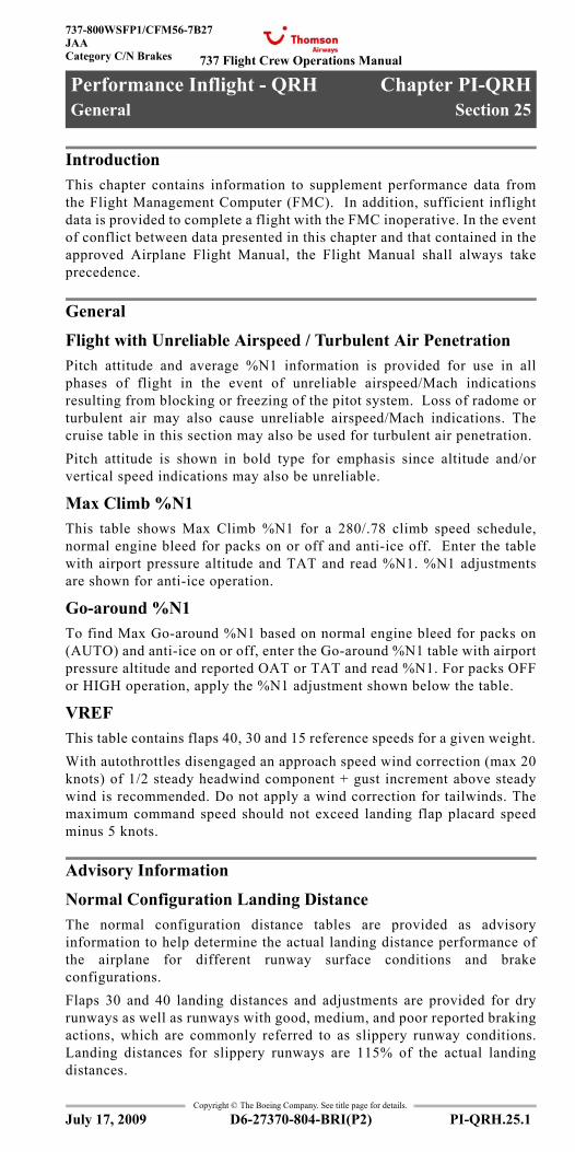
737 Flight Crew Operations Manual
Performance Inflight - QRH Chapter PI-QRHGeneral Section 25
737-800WSFP1/CFM56-7B27JAACategory C/N Brakes
Copyright © The Boeing Company. See title page for details.
D6-27370-804-BRI(P2) PI-QRH.25.1
PI-QRH.25 Performance Inflight - QRH-GeneralText
IntroductionThis chapter contains information to supplement performance data fromthe Flight Management Computer (FMC). In addition, sufficient inflightdata is provided to complete a flight with the FMC inoperative. In the eventof conflict between data presented in this chapter and that contained in theapproved Airplane Flight Manual, the Flight Manual shall always takeprecedence.
General
Flight with Unreliable Airspeed / Turbulent Air PenetrationPitch attitude and average %N1 information is provided for use in allphases of flight in the event of unreliable airspeed/Mach indicationsresulting from blocking or freezing of the pitot system. Loss of radome orturbulent air may also cause unreliable airspeed/Mach indications. Thecruise table in this section may also be used for turbulent air penetration.Pitch attitude is shown in bold type for emphasis since altitude and/orvertical speed indications may also be unreliable.
Max Climb %N1This table shows Max Climb %N1 for a 280/.78 climb speed schedule,normal engine bleed for packs on or off and anti-ice off. Enter the tablewith airport pressure altitude and TAT and read %N1. %N1 adjustmentsare shown for anti-ice operation.
Go-around %N1To find Max Go-around %N1 based on normal engine bleed for packs on(AUTO) and anti-ice on or off, enter the Go-around %N1 table with airportpressure altitude and reported OAT or TAT and read %N1. For packs OFFor HIGH operation, apply the %N1 adjustment shown below the table.
VREFThis table contains flaps 40, 30 and 15 reference speeds for a given weight.With autothrottles disengaged an approach speed wind correction (max 20knots) of 1/2 steady headwind component + gust increment above steadywind is recommended. Do not apply a wind correction for tailwinds. Themaximum command speed should not exceed landing flap placard speedminus 5 knots.
Advisory Information
Normal Configuration Landing DistanceThe normal configuration distance tables are provided as advisoryinformation to help determine the actual landing distance performance ofthe airplane for different runway surface conditions and brakeconfigurations.Flaps 30 and 40 landing distances and adjustments are provided for dryrunways as well as runways with good, medium, and poor reported brakingactions, which are commonly referred to as slippery runway conditions.Landing distances for slippery runways are 115% of the actual landingdistances.
July 17, 2009
General
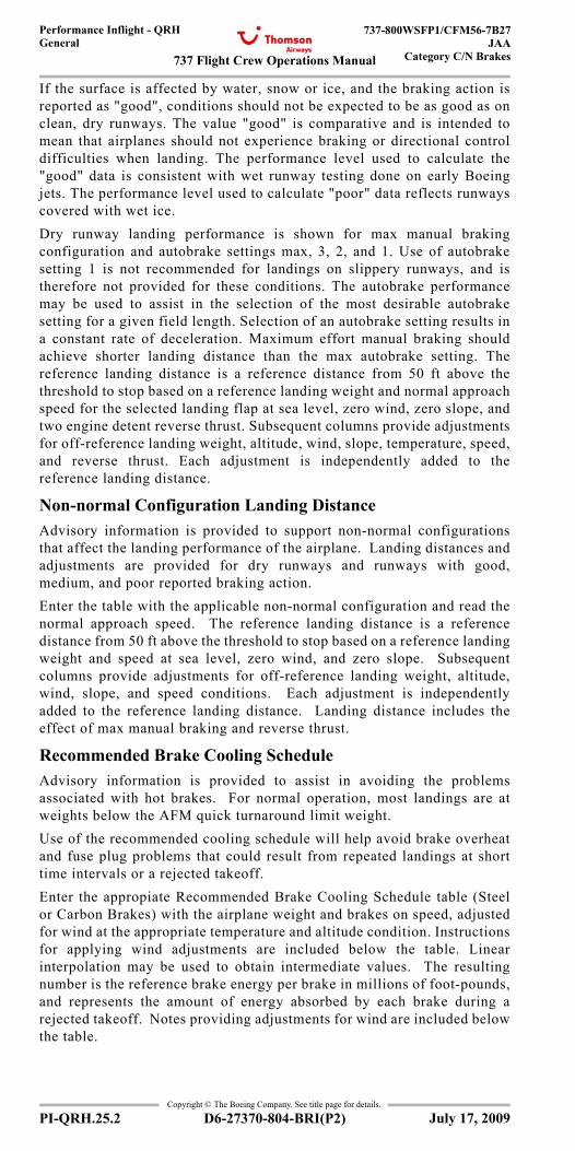
737 Flight Crew Operations Manual
Performance Inflight - QRHGeneral
737-800WSFP1/CFM56-7B27JAA
Category C/N Brakes
Copyright © The Boeing Company. See title page for details.
PI-QRH.25.2 D6-27370-804-BRI(P2)
If the surface is affected by water, snow or ice, and the braking action isreported as "good", conditions should not be expected to be as good as onclean, dry runways. The value "good" is comparative and is intended tomean that airplanes should not experience braking or directional controldifficulties when landing. The performance level used to calculate the"good" data is consistent with wet runway testing done on early Boeingjets. The performance level used to calculate "poor" data reflects runwayscovered with wet ice.Dry runway landing performance is shown for max manual brakingconfiguration and autobrake settings max, 3, 2, and 1. Use of autobrakesetting 1 is not recommended for landings on slippery runways, and istherefore not provided for these conditions. The autobrake performancemay be used to assist in the selection of the most desirable autobrakesetting for a given field length. Selection of an autobrake setting results ina constant rate of deceleration. Maximum effort manual braking shouldachieve shorter landing distance than the max autobrake setting. Thereference landing distance is a reference distance from 50 ft above thethreshold to stop based on a reference landing weight and normal approachspeed for the selected landing flap at sea level, zero wind, zero slope, andtwo engine detent reverse thrust. Subsequent columns provide adjustmentsfor off-reference landing weight, altitude, wind, slope, temperature, speed,and reverse thrust. Each adjustment is independently added to thereference landing distance.
Non-normal Configuration Landing DistanceAdvisory information is provided to support non-normal configurationsthat affect the landing performance of the airplane. Landing distances andadjustments are provided for dry runways and runways with good,medium, and poor reported braking action.Enter the table with the applicable non-normal configuration and read thenormal approach speed. The reference landing distance is a referencedistance from 50 ft above the threshold to stop based on a reference landingweight and speed at sea level, zero wind, and zero slope. Subsequentcolumns provide adjustments for off-reference landing weight, altitude,wind, slope, and speed conditions. Each adjustment is independentlyadded to the reference landing distance. Landing distance includes theeffect of max manual braking and reverse thrust.
Recommended Brake Cooling ScheduleAdvisory information is provided to assist in avoiding the problemsassociated with hot brakes. For normal operation, most landings are atweights below the AFM quick turnaround limit weight.Use of the recommended cooling schedule will help avoid brake overheatand fuse plug problems that could result from repeated landings at shorttime intervals or a rejected takeoff.Enter the appropiate Recommended Brake Cooling Schedule table (Steelor Carbon Brakes) with the airplane weight and brakes on speed, adjustedfor wind at the appropriate temperature and altitude condition. Instructionsfor applying wind adjustments are included below the table. Linearinterpolation may be used to obtain intermediate values. The resultingnumber is the reference brake energy per brake in millions of foot-pounds,and represents the amount of energy absorbed by each brake during arejected takeoff. Notes providing adjustments for wind are included belowthe table.
July 17, 2009
737 Flight Crew Operations Manual
Performance Inflight - QRHGeneral
737-800WSFP1/CFM56-7B27JAACategory C/N Brakes
Copyright © The Boeing Company. See title page for details.
D6-27370-804-BRI(P2) PI-QRH.25.3
To determine the energy per brake absorbed during landing, enter theappropriate Adjusted Brake Energy Per Brake table (No Reverse Thrust or2 Engine Reverse) with the reference brake energy per brake and the typeof braking used during landing (Max Manual, Max Auto, or Autobrake).The resulting number is the adjusted brake energy per brake and representsthe energy absorbed in each brake during the landing.The recommended cooling time is found in the final table by entering withthe adjusted brake energy per brake. Times are provided for groundcooling and inflight gear down cooling.Brake Temperature Monitor System (BTMS) indications are also shown. Ifbrake cooling is determined from the BTMS, use the hottest brakeindication 10 to 15 minutes after the airplane has come to a complete stop,or inflight with gear retracted to determine recommended coolingschedule.
Engine Inoperative
Initial Max Continuous %N1The Initial Max Continuous %N1 setting for use following an enginefailure is shown. The table is based on the typical all engine cruise speedof .79M to provide a target %N1 setting at the start of driftdown. Oncedriftdown is established, the Max Continuous %N1 table should be used todetermine %N1 for the given conditions.
Max Continuous %N1Power setting is based on one engine operating with one A/C packoperating and all anti-ice bleeds off. Enter the table with pressure altitude,TAT, and IAS or Mach to read %N1.It is desirable to maintain engine thrust level within the limits of the MaxCruise thrust rating. However, where thrust level in excess of Max Cruiserating is required, such as for meeting terrain clearance, ATC altitudeassignments, or to attain maximum range capability, it is permissible to usethe thrust needed up to the Max Continuous thrust rating. The MaxContinuous thrust rating is intended primarily for emergency use at thediscretion of the pilot and is the maximum thrust that may be usedcontinuously.
Driftdown Speed/Level Off AltitudeThe table shows optimum driftdown speed as a function of cruise weightat start of driftdown. Also shown are the approximate weight and pressurealtitude at which the airplane will level off considering 100 ft/min residualrate of climb. The level off altitude is dependent on air temperature (ISA deviation).
Driftdown/LRC Range CapabilityThis table shows the range capability from the start of driftdown.Driftdown is continued to level off altitude. As weight decreases due tofuel burn, the airplane is accelerated to Long Range Cruise speed. Cruiseis continued at level off altitude and Long Range Cruise speed.To determine fuel required, enter the Ground to Air Miles Conversion tablewith the desired ground distance and adjust for anticipated winds to obtainair distance to destination. Then enter the Driftdown/Cruise Fuel and Timetable with air distance and weight at start of driftdown to determine fuel
July 17, 2009
737 Flight Crew Operations Manual
Performance Inflight - QRHGeneral
737-800WSFP1/CFM56-7B27JAA
Category C/N Brakes
Copyright © The Boeing Company. See title page for details.
PI-QRH.25.4 D6-27370-804-BRI(P2)
and time required. If altitudes other than the level off altitude is used, fueland time required may be obtained by using the Engine Inoperative LongRange Cruise Enroute Fuel and Time table.
Long Range Cruise Altitude CapabilityThe table shows the maximum altitude that can be maintained at a givenweight and air temperature (ISA deviation), based on Long Range Cruisespeed, Max Continuous thrust, and 100 ft/min residual rate of climb.
Long Range Cruise ControlThe table provides target %N1, engine inoperative Long Range CruiseMach number, IAS and fuel flow for the airplane weight and pressurealtitude. The fuel flow values in this table reflect single engine fuel burn.
Long Range Cruise Diversion Fuel and TimeTables are provided for crews to determine the fuel and time required toproceed to an alternate airfield with one engine inoperative. The data isbased on single engine Long Range Cruise speed and .78/280/250 descent.Enter with Air Distance as determined from the Ground to Air MilesConversion table and read Fuel and Time required at the cruise pressurealtitude. Adjust the fuel obtained for deviation from the reference weightat checkpoint as required by entering the off reference fuel adjustmentstable with the fuel required for the reference weight and the actual weightat checkpoint. Read fuel required and time for the actual weight.
HoldingTarget %N1, indicated airspeed and fuel flow per engine information istabulated for holding with flaps up based on the FMC optimum holdingspeed schedule. This is the higher of the maximum endurance speed andthe maneuvering speed. Small variations in airspeed will not appreciablyaffect the overall endurance time. Enter the table with weight and pressurealtitude to read %N1, IAS and fuel flow per engine.
Gear Down Landing Rate of Climb AvailableRate of climb data is provided as guidance information in the event anengine inoperative landing (manual or autoland) is planned. The tablesshow gear down rate of climb available for Flaps 15 and Flaps 30. Enterthe table with TAT and pressure altitude to read rate of climb available.Apply adjustments shown to correct for weight.
Gear DownThis section contains performance for airplane operation with the landinggear extended. The data is based on engine bleeds for normal airconditioning.Note: The Flight Management Computer System (FMCS) does not containspecial provisions for operation with landing gear extended. As a result,the FMCS may generate inappropriate enroute speed schedules, displaynon-conservative predictions of fuel burn, estimated time of arrival (ETA),maximum altitude, and compute overly shallow descent path. An accurateestimated time of arrival (ETA) is available if current speed or Mach isentered into the VNAV cruise page. Tables for gear down performance in this section are identical in formatand used in the same manner as tables for the gear up configurationpreviously described.
July 17, 2009
737 Flight Crew Operations Manual
Maneuvers Chapter ManTable of Contents Section 0
Copyright © The Boeing Company. See title page for details.
D6-27370-804-BRI(P2) Man.TOC.0.1
Introduction . . . . . . . . . . . . . . . . . . . . . . . . . . . . . . . . . . . . . . MAN.05General. . . . . . . . . . . . . . . . . . . . . . . . . . . . . . . . . . . . . . . . . . MAN.05.1Non-Normal Maneuvers . . . . . . . . . . . . . . . . . . . . . . . . . . . . MAN.05.1Flight Patterns . . . . . . . . . . . . . . . . . . . . . . . . . . . . . . . . . . . . MAN.05.1
Non-Normal Maneuvers . . . . . . . . . . . . . . . . . . . . . . . . . . . . . MAN.1Approach to Stall Recovery . . . . . . . . . . . . . . . . . . . . . . . . . . . MAN.1.1Rejected Takeoff < BRI > . . . . . . . . . . . . . . . . . . . . . . . . . . . . MAN.1.1Terrain Avoidance . . . . . . . . . . . . . . . . . . . . . . . . . . . . . . . . . . MAN.1.3
Ground Proximity Caution . . . . . . . . . . . . . . . . . . . . . . . . . MAN.1.3Ground Proximity Warning . . . . . . . . . . . . . . . . . . . . . . . . MAN.1.3
Traffic Avoidance . . . . . . . . . . . . . . . . . . . . . . . . . . . . . . . . . . MAN.1.4Upset Recovery . . . . . . . . . . . . . . . . . . . . . . . . . . . . . . . . . . . . MAN.1.6
Nose High Recovery. . . . . . . . . . . . . . . . . . . . . . . . . . . . . . MAN.1.6Nose Low Recovery . . . . . . . . . . . . . . . . . . . . . . . . . . . . . . MAN.1.7
Windshear . . . . . . . . . . . . . . . . . . . . . . . . . . . . . . . . . . . . . . . . MAN.1.7Windshear Caution . . . . . . . . . . . . . . . . . . . . . . . . . . . . . . . MAN.1.7Windshear Warning . . . . . . . . . . . . . . . . . . . . . . . . . . . . . . MAN.1.7Windshear Escape Maneuver . . . . . . . . . . . . . . . . . . . . . . . MAN.1.8
Flight Patterns . . . . . . . . . . . . . . . . . . . . . . . . . . . . . . . . . . . . . MAN.2Takeoff. . . . . . . . . . . . . . . . . . . . . . . . . . . . . . . . . . . . . . . . . . . MAN.2.1Takeoff. . . . . . . . . . . . . . . . . . . . . . . . . . . . . . . . . . . . . . . . . . . MAN.2.2ILS Approach - Fail Passive . . . . . . . . . . . . . . . . . . . . . . . . . . MAN.2.3ILS Approach - Fail Operational . . . . . . . . . . . . . . . . . . . . . . . MAN.2.4Instrument Approach Using VNAV . . . . . . . . . . . . . . . . . . . . MAN.2.5Instrument Approach Using V/S . . . . . . . . . . . . . . . . . . . . . . . MAN.2.6Circling Approach . . . . . . . . . . . . . . . . . . . . . . . . . . . . . . . . . . MAN.2.7Visual Traffic Pattern. . . . . . . . . . . . . . . . . . . . . . . . . . . . . . . . MAN.2.8Go–Around and Missed Approach . . . . . . . . . . . . . . . . . . . . . MAN.2.9
July 17, 2009
ManeuversTable Of Contents
737 Flight Crew Operations Manual
Maneuvers -Table of Contents
Copyright © The Boeing Company. See title page for details.
Man.TOC.0.2 D6-27370-804-BRI(P2)
IntentionallyBlank
July 17, 2009
737 Flight Crew Operations Manual
Maneuvers Chapter MANIntroduction Section 05
Copyright © The Boeing Company. See title page for details.
D6-27370-804-BRI(P2) MAN.05.1
MAN.05 Maneuvers-IntroductionIntroductionIntroduction
GeneralNon-Normal Maneuvers and Flight Patterns are included for training and review purposes.
Non-Normal ManeuversFlight crews are expected to do non-normal maneuvers from memory.
Flight PatternsFlight patterns show procedures for some all-engine and engine-inoperative situations.Flight patterns do not include all procedural items but show required/recommended:
• configuration changes• thrust changes• Mode Control Panel (MCP) changes• pitch mode and roll mode changes• checklist calls.
July 17, 2009

737 Flight Crew Operations Manual
Maneuvers -Introduction
Copyright © The Boeing Company. See title page for details.
MAN.05.2 D6-27370-804-BRI(P2)
IntentionallyBlank
July 17, 2009
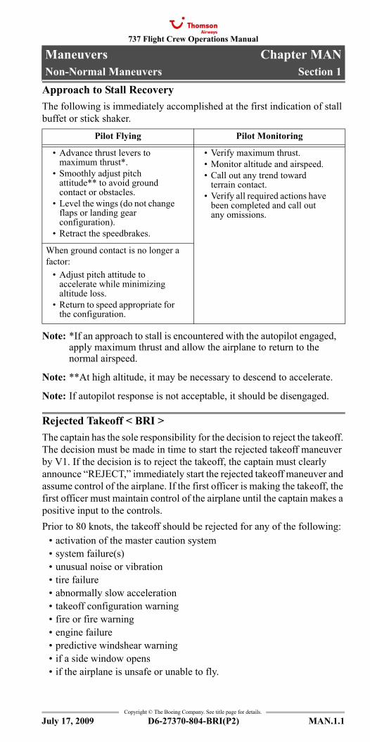
737 Flight Crew Operations Manual
Maneuvers Chapter MANNon-Normal Maneuvers Section 1
Copyright © The Boeing Company. See title page for details.
D6-27370-804-BRI(P2) MAN.1.1
MAN.1 Maneuvers-Non-Normal ManeuversNon-Normal ManeuversNon-Normal Maneuvers
Approach to Stall RecoveryThe following is immediately accomplished at the first indication of stall buffet or stick shaker.
Note: *If an approach to stall is encountered with the autopilot engaged, apply maximum thrust and allow the airplane to return to the normal airspeed.
Note: **At high altitude, it may be necessary to descend to accelerate.
Note: If autopilot response is not acceptable, it should be disengaged.
Rejected Takeoff < BRI >The captain has the sole responsibility for the decision to reject the takeoff. The decision must be made in time to start the rejected takeoff maneuver by V1. If the decision is to reject the takeoff, the captain must clearly announce “REJECT,” immediately start the rejected takeoff maneuver and assume control of the airplane. If the first officer is making the takeoff, the first officer must maintain control of the airplane until the captain makes a positive input to the controls.Prior to 80 knots, the takeoff should be rejected for any of the following:
• activation of the master caution system• system failure(s)• unusual noise or vibration• tire failure• abnormally slow acceleration• takeoff configuration warning• fire or fire warning• engine failure• predictive windshear warning• if a side window opens• if the airplane is unsafe or unable to fly.
Pilot Flying Pilot Monitoring
• Advance thrust levers to maximum thrust*.
• Smoothly adjust pitch attitude** to avoid ground contact or obstacles.
• Level the wings (do not change flaps or landing gear configuration).
• Retract the speedbrakes.
• Verify maximum thrust.• Monitor altitude and airspeed.• Call out any trend toward
terrain contact.• Verify all required actions have
been completed and call out any omissions.
When ground contact is no longer a factor:
• Adjust pitch attitude to accelerate while minimizing altitude loss.
• Return to speed appropriate for the configuration.
July 17, 2009
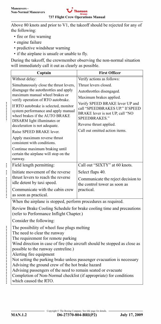
737 Flight Crew Operations Manual
Maneuvers -Non-Normal Maneuvers
Copyright © The Boeing Company. See title page for details.
MAN.1.2 D6-27370-804-BRI(P2)
Above 80 knots and prior to V1, the takeoff should be rejected for any of the following:
• fire or fire warning• engine failure• predictive windshear warning• if the airplane is unsafe or unable to fly.
During the takeoff, the crewmember observing the non-normal situation will immediately call it out as clearly as possible.
Captain First OfficerWithout delay:Simultaneously close the thrust levers, disengage the autothrottles and apply maximum manual wheel brakes or verify operation of RTO autobrake.If RTO autobrake is selected, monitor system performance and apply manual wheel brakes if the AUTO BRAKE DISARM light illuminates or deceleration is not adequate.Raise SPEED BRAKE lever.Apply maximum reverse thrust consistent with conditions.Continue maximum braking until certain the airplane will stop on the runway.
Verify actions as follows:Thrust levers closed.Autothrottles disengaged.Maximum brakes applied.Verify SPEED BRAKE lever UP and call “SPEEDBRAKES UP.” If SPEED BRAKE lever is not UP, call “NO SPEEDBRAKES.”Reverse thrust applied.Call out omitted action items.
Field length permitting:Initiate movement of the reverse thrust levers to reach the reverse idle detent by taxi speed.Communicate with the cabin crew as soon as practical.
Call out “SIXTY” at 60 knots.Select flaps 40.Communicate the reject decision to the control tower as soon as practical.
When the airplane is stopped, perform procedures as required.Review Brake Cooling Schedule for brake cooling time and precautions (refer to Performance Inflight Chapter.)Consider the following:The possibility of wheel fuse plugs meltingThe need to clear the runwayThe requirement for remote parkingWind direction in case of fire (the aircraft should be stopped as close as possible to the runway centreline.)Alerting fire equipmentNot setting the parking brake unless passenger evacuation is necessaryAdvising the ground crew of the hot brake hazardAdvising passengers of the need to remain seated or evacuateCompletion of Non-Normal checklist (if appropriate) for conditions which caused the RTO.
July 17, 2009
:::::::
::::
:::::::::
::::::::::::::::::
:
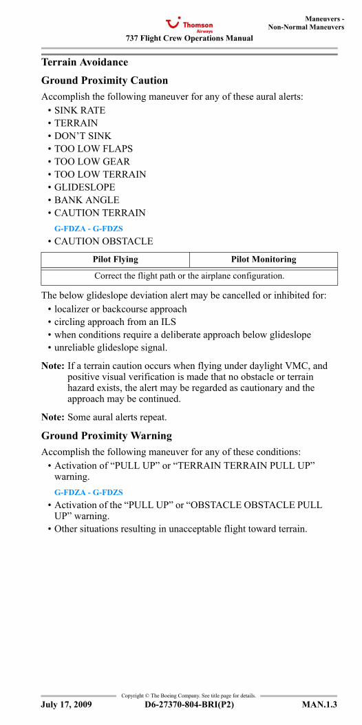
737 Flight Crew Operations Manual
Maneuvers -Non-Normal Maneuvers
Copyright © The Boeing Company. See title page for details.
D6-27370-804-BRI(P2) MAN.1.3
Terrain Avoidance
Ground Proximity CautionAccomplish the following maneuver for any of these aural alerts:
• SINK RATE• TERRAIN• DON’T SINK• TOO LOW FLAPS• TOO LOW GEAR• TOO LOW TERRAIN• GLIDESLOPE• BANK ANGLE• CAUTION TERRAIN
G-FDZA - G-FDZS• CAUTION OBSTACLE
The below glideslope deviation alert may be cancelled or inhibited for:• localizer or backcourse approach• circling approach from an ILS• when conditions require a deliberate approach below glideslope• unreliable glideslope signal.
Note: If a terrain caution occurs when flying under daylight VMC, and positive visual verification is made that no obstacle or terrain hazard exists, the alert may be regarded as cautionary and the approach may be continued.
Note: Some aural alerts repeat.
Ground Proximity WarningAccomplish the following maneuver for any of these conditions:
• Activation of “PULL UP” or “TERRAIN TERRAIN PULL UP” warning.G-FDZA - G-FDZS
• Activation of the “PULL UP” or “OBSTACLE OBSTACLE PULL UP” warning.
• Other situations resulting in unacceptable flight toward terrain.
Pilot Flying Pilot Monitoring
Correct the flight path or the airplane configuration.
July 17, 2009
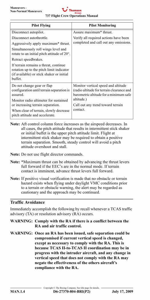
737 Flight Crew Operations Manual
Maneuvers -Non-Normal Maneuvers
Copyright © The Boeing Company. See title page for details.
MAN.1.4 D6-27370-804-BRI(P2)
Note: Aft control column force increases as the airspeed decreases. In all cases, the pitch attitude that results in intermittent stick shaker or initial buffet is the upper pitch attitude limit. Flight at intermittent stick shaker may be required to obtain a positive terrain separation. Smooth, steady control will avoid a pitch attitude overshoot and stall.
Note: Do not use flight director commands.
Note: *Maximum thrust can be obtained by advancing the thrust levers full forward if the EEC’s are in the normal mode. If terrain contact is imminent, advance thrust levers full forward.
Note: If positive visual verification is made that no obstacle or terrain hazard exists when flying under daylight VMC conditions prior to a terrain or obstacle warning, the alert may be regarded as cautionary and the approach may be continued.
Traffic AvoidanceImmediately accomplish the following by recall whenever a TCAS traffic advisory (TA) or resolution advisory (RA) occurs.
WARNING: Comply with the RA if there is a conflict between the RA and air traffic control.
WARNING: Once an RA has been issued, safe separation could be compromised if current vertical speed is changed, except as necessary to comply with the RA. This is because TCAS II-to-TCAS II coordination may be in progress with the intruder aircraft, and any change in vertical speed that does not comply with the RA may negate the effectiveness of the others aircraft’s compliance with the RA.
Pilot Flying Pilot Monitoring
Disconnect autopilot.Disconnect autothrottle.Aggressively apply maximum* thrust.Simultaneously roll wings level and rotate to an initial pitch attitude of 20°.Retract speedbrakes.If terrain remains a threat, continue rotation up to the pitch limit indicator (if available) or stick shaker or initial buffet.
Assure maximum* thrust.Verify all required actions have been completed and call out any omissions.
Do not change gear or flap configuration until terrain separation is assured.Monitor radio altimeter for sustained or increasing terrain separation.When clear of terrain, slowly decrease pitch attitude and accelerate.
Monitor vertical speed and altitude (radio altitude for terrain clearance and barometric altitude for a minimum safe altitude.)Call out any trend toward terrain contact.
July 17, 2009
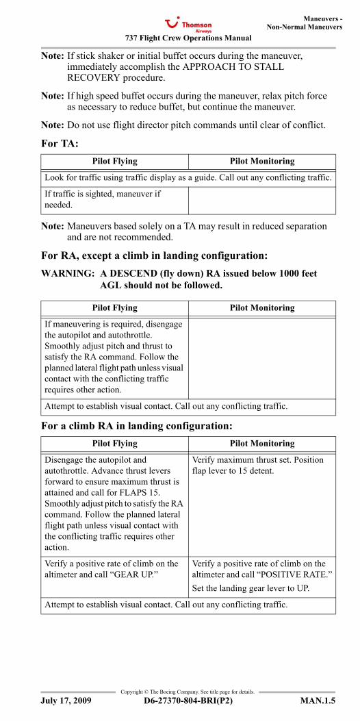
737 Flight Crew Operations Manual
Maneuvers -Non-Normal Maneuvers
Copyright © The Boeing Company. See title page for details.
D6-27370-804-BRI(P2) MAN.1.5
Note: If stick shaker or initial buffet occurs during the maneuver, immediately accomplish the APPROACH TO STALL RECOVERY procedure.
Note: If high speed buffet occurs during the maneuver, relax pitch force as necessary to reduce buffet, but continue the maneuver.
Note: Do not use flight director pitch commands until clear of conflict.
For TA:
Note: Maneuvers based solely on a TA may result in reduced separation and are not recommended.
For RA, except a climb in landing configuration:WARNING: A DESCEND (fly down) RA issued below 1000 feet
AGL should not be followed.
For a climb RA in landing configuration:
Pilot Flying Pilot Monitoring
Look for traffic using traffic display as a guide. Call out any conflicting traffic.
If traffic is sighted, maneuver if needed.
Pilot Flying Pilot Monitoring
If maneuvering is required, disengage the autopilot and autothrottle. Smoothly adjust pitch and thrust to satisfy the RA command. Follow the planned lateral flight path unless visual contact with the conflicting traffic requires other action.
Attempt to establish visual contact. Call out any conflicting traffic.
Pilot Flying Pilot Monitoring
Disengage the autopilot and autothrottle. Advance thrust levers forward to ensure maximum thrust is attained and call for FLAPS 15. Smoothly adjust pitch to satisfy the RA command. Follow the planned lateral flight path unless visual contact with the conflicting traffic requires other action.
Verify maximum thrust set. Position flap lever to 15 detent.
Verify a positive rate of climb on the altimeter and call “GEAR UP.”
Verify a positive rate of climb on the altimeter and call “POSITIVE RATE.”Set the landing gear lever to UP.
Attempt to establish visual contact. Call out any conflicting traffic.
July 17, 2009
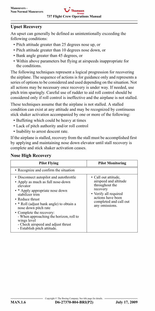
737 Flight Crew Operations Manual
Maneuvers -Non-Normal Maneuvers
Copyright © The Boeing Company. See title page for details.
MAN.1.6 D6-27370-804-BRI(P2)
Upset RecoveryAn upset can generally be defined as unintentionally exceeding the following conditions:
• Pitch attitude greater than 25 degrees nose up, or• Pitch attitude greater than 10 degrees nose down, or• Bank angle greater than 45 degrees, or• Within above parameters but flying at airspeeds inappropriate for
the conditions.The following techniques represent a logical progression for recovering the airplane. The sequence of actions is for guidance only and represents a series of options to be considered and used depending on the situation. Not all actions may be necessary once recovery is under way. If needed, use pitch trim sparingly. Careful use of rudder to aid roll control should be considered only if roll control is ineffective and the airplane is not stalled.These techniques assume that the airplane is not stalled. A stalled condition can exist at any attitude and may be recognized by continuous stick shaker activation accompanied by one or more of the following:
• Buffeting which could be heavy at times• Lack of pitch authority and/or roll control• Inability to arrest descent rate.
If the airplane is stalled, recovery from the stall must be accomplished first by applying and maintaining nose down elevator until stall recovery is complete and stick shaker activation ceases.
Nose High RecoveryPilot Flying Pilot Monitoring
• Recognize and confirm the situation
• Disconnect autopilot and autothrottle• Apply as much as full nose-down
elevator• * Apply appropriate nose down
stabilizer trim• Reduce thrust• * Roll (adjust bank angle) to obtain a
nose down pitch rate• Complete the recovery:
- When approaching the horizon, roll to wings level- Check airspeed and adjust thrust- Establish pitch attitude.
• Call out attitude, airspeed and altitude throughout the recovery
• Verify all required actions have been completed and call out any omissions.
July 17, 2009
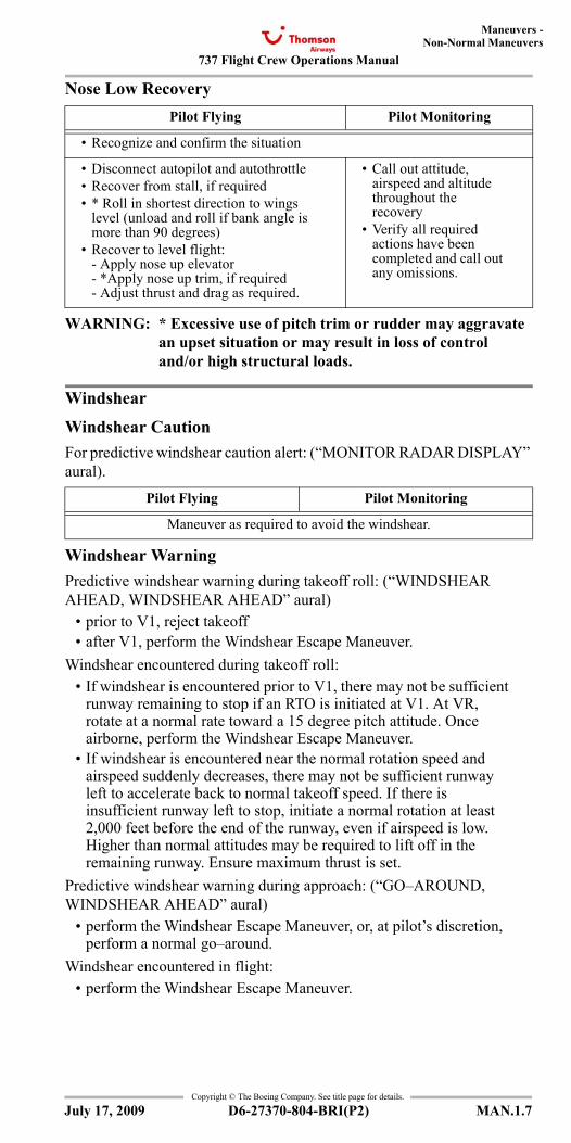
737 Flight Crew Operations Manual
Maneuvers -Non-Normal Maneuvers
Copyright © The Boeing Company. See title page for details.
D6-27370-804-BRI(P2) MAN.1.7
Nose Low Recovery
WARNING: * Excessive use of pitch trim or rudder may aggravate an upset situation or may result in loss of control and/or high structural loads.
Windshear
Windshear CautionFor predictive windshear caution alert: (“MONITOR RADAR DISPLAY” aural).
Windshear WarningPredictive windshear warning during takeoff roll: (“WINDSHEAR AHEAD, WINDSHEAR AHEAD” aural)
• prior to V1, reject takeoff• after V1, perform the Windshear Escape Maneuver.
Windshear encountered during takeoff roll:• If windshear is encountered prior to V1, there may not be sufficient
runway remaining to stop if an RTO is initiated at V1. At VR, rotate at a normal rate toward a 15 degree pitch attitude. Once airborne, perform the Windshear Escape Maneuver.
• If windshear is encountered near the normal rotation speed and airspeed suddenly decreases, there may not be sufficient runway left to accelerate back to normal takeoff speed. If there is insufficient runway left to stop, initiate a normal rotation at least 2,000 feet before the end of the runway, even if airspeed is low. Higher than normal attitudes may be required to lift off in the remaining runway. Ensure maximum thrust is set.
Predictive windshear warning during approach: (“GO–AROUND, WINDSHEAR AHEAD” aural)
• perform the Windshear Escape Maneuver, or, at pilot’s discretion, perform a normal go–around.
Windshear encountered in flight:• perform the Windshear Escape Maneuver.
Pilot Flying Pilot Monitoring
• Recognize and confirm the situation
• Disconnect autopilot and autothrottle• Recover from stall, if required• * Roll in shortest direction to wings
level (unload and roll if bank angle is more than 90 degrees)
• Recover to level flight:- Apply nose up elevator- *Apply nose up trim, if required- Adjust thrust and drag as required.
• Call out attitude, airspeed and altitude throughout the recovery
• Verify all required actions have been completed and call out any omissions.
Pilot Flying Pilot Monitoring
Maneuver as required to avoid the windshear.
July 17, 2009
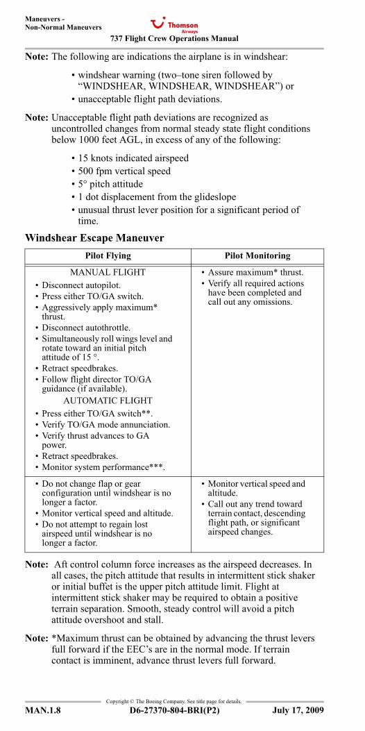
737 Flight Crew Operations Manual
Maneuvers -Non-Normal Maneuvers
Copyright © The Boeing Company. See title page for details.
MAN.1.8 D6-27370-804-BRI(P2)
Note: The following are indications the airplane is in windshear:
• windshear warning (two–tone siren followed by “WINDSHEAR, WINDSHEAR, WINDSHEAR”) or
• unacceptable flight path deviations.
Note: Unacceptable flight path deviations are recognized as uncontrolled changes from normal steady state flight conditions below 1000 feet AGL, in excess of any of the following:
• 15 knots indicated airspeed• 500 fpm vertical speed• 5° pitch attitude• 1 dot displacement from the glideslope• unusual thrust lever position for a significant period of
time.
Windshear Escape Maneuver
Note: Aft control column force increases as the airspeed decreases. In all cases, the pitch attitude that results in intermittent stick shaker or initial buffet is the upper pitch attitude limit. Flight at intermittent stick shaker may be required to obtain a positive terrain separation. Smooth, steady control will avoid a pitch attitude overshoot and stall.
Note: *Maximum thrust can be obtained by advancing the thrust levers full forward if the EEC’s are in the normal mode. If terrain contact is imminent, advance thrust levers full forward.
Pilot Flying Pilot Monitoring
MANUAL FLIGHT• Disconnect autopilot.• Press either TO/GA switch.• Aggressively apply maximum*
thrust.• Disconnect autothrottle.• Simultaneously roll wings level and
rotate toward an initial pitch attitude of 15 °.
• Retract speedbrakes.• Follow flight director TO/GA
guidance (if available).AUTOMATIC FLIGHT
• Press either TO/GA switch**.• Verify TO/GA mode annunciation.• Verify thrust advances to GA
power.• Retract speedbrakes.• Monitor system performance***.
• Assure maximum* thrust.• Verify all required actions
have been completed and call out any omissions.
• Do not change flap or gear configuration until windshear is no longer a factor.
• Monitor vertical speed and altitude.• Do not attempt to regain lost
airspeed until windshear is no longer a factor.
• Monitor vertical speed and altitude.
• Call out any trend toward terrain contact, descending flight path, or significant airspeed changes.
July 17, 2009
737 Flight Crew Operations Manual
Maneuvers -Non-Normal Maneuvers
Copyright © The Boeing Company. See title page for details.
D6-27370-804-BRI(P2) MAN.1.9
Note: ** If TO/GA is not available, disconnect autopilot and autothrottle and fly manually.
WARNING: *** Severe windshear may exceed the performance of the AFDS. The pilot flying must be prepared to disconnect the autopilot and autothrottle and fly manually.
July 17, 2009
737 Flight Crew Operations Manual
Maneuvers -Non-Normal Maneuvers
Copyright © The Boeing Company. See title page for details.
MAN.1.10 D6-27370-804-BRI(P2)
IntentionallyBlank
July 17, 2009
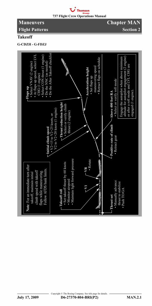
737 Flight Crew Operations Manual
Maneuvers Chapter MANFlight Patterns Section 2
Copyright © The Boeing Company. See title page for details.
D6-27370-804-BRI(P2) MAN.2.1
MAN.2 Maneuvers-Flight PatternsFlight PatternsFlight Patterns
TakeoffG-CDZH - G-FDZJ
Posi
tive
rate
of c
limb
• R
etra
ct g
ear
Abo
ve 4
00 fe
et R
A •
Sel
ect o
r ver
ify ro
ll m
ode
Acc
eler
atio
n he
ight
• S
et fl
aps u
p
man
euve
ring
spee
d •
Ret
ract
flap
s on
sche
dule
Enga
ge th
e au
topi
lot w
hen
abov
e m
inim
um
Thr
ust s
et •
Man
ually
adv
ance
t
hrus
t to
stab
ilize
• P
ush
TO/G
AV1
VR
• R
otat
e
Take
off r
oll
• S
et ta
keof
f thr
ust b
y 60
kno
ts •
Mon
itor a
irspe
ed •
Mai
ntai
n lig
ht fo
rwar
d pr
essu
re
Note
: For
an im
med
iate t
urn
after
t
akeo
ff, m
aint
ain
initi
al
clim
b sp
eed
with
take
off
fl
aps w
hile
man
euve
ring.
Fol
low
AFDS
ban
k lim
its.
Initi
al c
limb
spee
d
Thr
ust r
educ
tion
heig
ht •
Sel
ect o
r ver
ify c
limb
t
hrus
t (2
engi
ne)
• V
2+15
to V
2+25
kno
ts, o
r
V2
to V
2+20
kno
ts (1
eng
ine)
Flap
s up
• S
elec
t VN
AV (2
eng
ine)
• A
t fla
ps u
p sp
eed,
sele
ct L
VL
C
HG
(1 e
ngin
e) •
Sel
ect C
ON
thru
st (1
eng
ine)
• D
o th
e N
NC
(as n
eede
d) •
Do
the
Afte
r Tak
eoff
chec
klis
t
altit
ude
for a
utop
ilot e
ngag
emen
t (2
engi
ne)
or a
fter a
roll
mod
e an
d LV
L C
HG
are
enga
ged
(1 e
ngin
e).
July 17, 2009
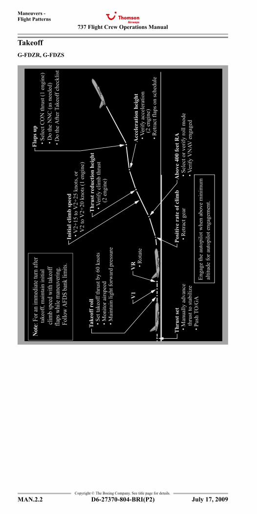
737 Flight Crew Operations Manual
Maneuvers -Flight Patterns
Copyright © The Boeing Company. See title page for details.
MAN.2.2 D6-27370-804-BRI(P2)
TakeoffG-FDZR, G-FDZS
Posi
tive
rate
of c
limb
• R
etra
ct g
ear
Abo
ve 4
00 fe
et R
A •
Sel
ect o
r ver
ify ro
ll m
ode
Acc
eler
atio
n he
ight
• V
erify
acc
eler
atio
n •
Ret
ract
flap
s on
sche
dule
Enga
ge th
e au
topi
lot w
hen
abov
e m
inim
um
Thr
ust s
et •
Man
ually
adv
ance
t
hrus
t to
stab
ilize
• P
ush
TO/G
AV1
VR
• R
otat
e
Take
off r
oll
• S
et ta
keof
f thr
ust b
y 60
kno
ts •
Mon
itor a
irspe
ed •
Mai
ntai
n lig
ht fo
rwar
d pr
essu
re
Note
: For
an im
med
iate t
urn
after
t
akeo
ff, m
aint
ain
initi
al
clim
b sp
eed
with
take
off
fl
aps w
hile
man
euve
ring.
Fol
low
AFDS
ban
k lim
its.
Initi
al c
limb
spee
d
Thr
ust r
educ
tion
heig
ht •
Ver
ify c
limb
thru
st (2
eng
ine)
• V
2+15
to V
2+25
kno
ts, o
r
V2
to V
2+20
kno
ts (1
eng
ine)
Flap
s up
• S
elec
t CO
N th
rust
(1 e
ngin
e) •
Do
the
NN
C (a
s nee
ded)
• D
o th
e A
fter T
akeo
ff ch
eckl
ist
altit
ude
for a
utop
ilot e
ngag
emen
t.
(2 e
ngin
e)
• V
erify
VN
AV e
ngag
ed
July 17, 2009
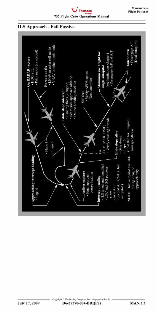
737 Flight Crew Operations Manual
Maneuvers -Flight Patterns
Copyright © The Boeing Company. See title page for details.
D6-27370-804-BRI(P2) MAN.2.3
ILS Approach - Fail Passive
On
RA
DA
R v
ecto
rs •
HD
G S
EL •
Pitc
h m
ode
(as n
eede
d)
Enr
oute
to fi
x •
LN
AV o
r oth
er ro
ll m
ode
• V
NAV
or o
ther
pitc
h m
ode
Glid
e sl
ope
inte
rcep
t •
Lan
ding
flap
s (2
engi
ne)
• S
et m
isse
d ap
proa
ch a
ltitu
de •
Do
the
Land
ing
chec
klis
t
500
feet
• V
erify
AFD
S st
atus
(D
ual a
utop
ilot)
Min
imum
use
hei
ght f
or
(see
lim
itatio
ns c
hapt
er)
• D
isen
gage
A/P
and
A/T
Touc
hdow
n •
Dis
enga
ge A
/P
(Dua
l aut
opilo
t)
Fix
(LO
M, M
KR
, DM
E) •
Ver
ify c
ross
ing
altit
ude
Glid
e sl
ope
aliv
e •
Gea
r dow
n •
Fla
ps 1
5
(fin
al fl
ap fo
r 1 e
ngin
e) •
Arm
spee
dbra
ke
App
roac
hing
inte
rcep
t hea
ding
• F
laps
5
• Fla
ps 5
• Fla
ps 1
Loc
aliz
er c
aptu
re •
Fin
al a
ppro
ach
c
ours
e he
adin
g
Inte
rcep
t hea
ding
• IL
S tu
ned
and
iden
tifie
d •
LO
C a
nd G
/S p
oint
ers
s
how
n •
Arm
APP
• S
econ
d A
/P C
MD
(Dua
l
aut
opilo
t.)
NO
TE
: Dua
l aut
opilo
t ava
ilabl
e
d
urin
g 2
engi
ne
a
ppro
ach
only
.
sing
le a
utop
ilot
July 17, 2009
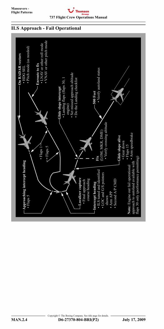
737 Flight Crew Operations Manual
Maneuvers -Flight Patterns
Copyright © The Boeing Company. See title page for details.
MAN.2.4 D6-27370-804-BRI(P2)
ILS Approach - Fail Operational
On
RA
DA
R v
ecto
rs
• Fla
ps 1
• Fla
ps 5
• H
DG
SEL
• P
itch
mod
e (a
s nee
ded)
Enr
oute
to fi
x •
LN
AV o
r oth
er ro
ll m
ode
• V
NAV
or o
ther
pitc
h m
ode
Glid
e sl
ope
inte
rcep
t •
Lan
ding
flap
s (fla
ps 3
0, 1
e
ngin
e) •
Set
mis
sed
appr
oach
alti
tude
• D
o th
e La
ndin
g ch
eckl
ist
500
Feet
• V
erify
aut
olan
d st
atus
Fi
x(L
OM
, MK
R, D
ME)
• V
erify
cro
ssin
g al
titud
e
Glid
e sl
ope
aliv
e •
Gea
r dow
n •
Fla
ps 1
5 •
Arm
spee
dbra
ke
App
roac
hing
inte
rcep
t hea
ding
• F
laps
5
Loc
aliz
er c
aptu
re •
Fin
al a
ppro
ach
c
ours
e he
adin
g
Inte
rcep
t hea
ding
• IL
S tu
ned
and
iden
tifie
d •
LO
C a
nd G
/S p
oint
ers
s
how
n •
Arm
APP
• S
econ
d A
/P C
MD
Not
e: E
ngin
e ou
t fai
l ope
ratio
nal
appr
oach
to a
utol
and
avai
labl
e w
ithfla
ps 3
0 on
ly (p
erfo
rman
ce p
erm
ittin
g)
July 17, 2009
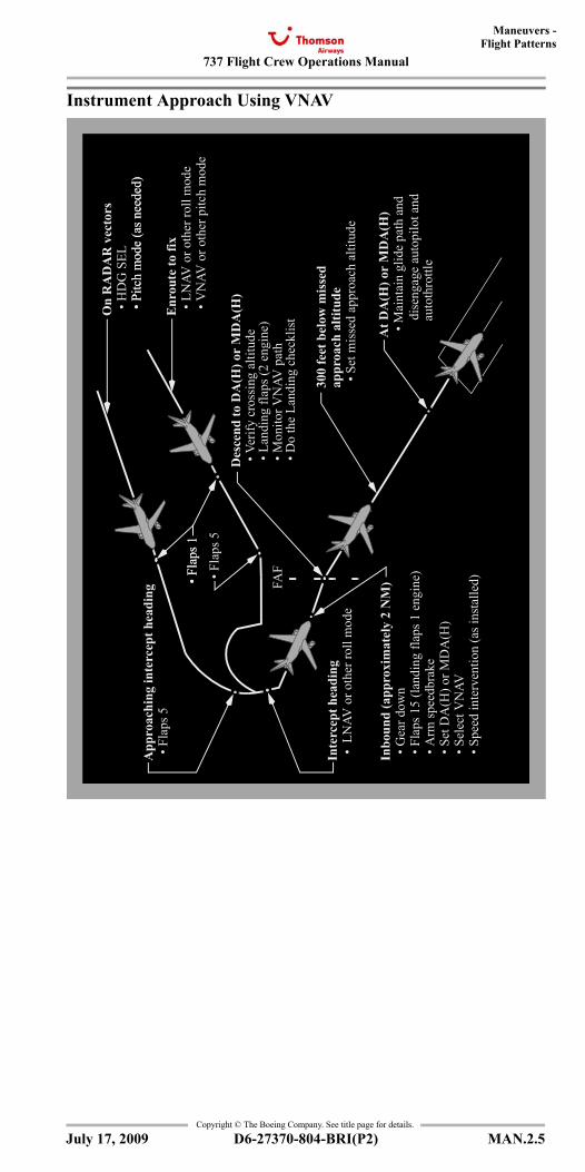
737 Flight Crew Operations Manual
Maneuvers -Flight Patterns
Copyright © The Boeing Company. See title page for details.
D6-27370-804-BRI(P2) MAN.2.5
Instrument Approach Using VNAV
On
RA
DA
R v
ecto
rs
• Fla
ps 5
• Fla
ps 1
• H
DG
SEL
• P
itch
mod
e (a
s nee
ded)
Enr
oute
to fi
x •
LN
AV o
r oth
er ro
ll m
ode
• V
NAV
or o
ther
pitc
h m
ode
Des
cend
to D
A(H
) or
MD
A(H
)
• M
onito
r VN
AV p
ath
• D
o th
e La
ndin
g ch
eckl
ist
300
feet
bel
ow m
isse
dap
proa
ch a
ltitu
de •
Set
mis
sed
appr
oach
alti
tude
At D
A(H
) or
MD
A(H
) •
Mai
ntai
n gl
ide
path
and
App
roac
hing
inte
rcep
t hea
ding
• F
laps
5
Inte
rcep
t hea
ding
• L
NAV
or o
ther
roll
mod
e
Inbo
und
(app
roxi
mat
ely
2 N
M)
• G
ear d
own
• F
laps
15
(land
ing
flaps
1 e
ngin
e) •
Arm
spee
dbra
ke •
Set
DA
(H) o
r MD
A(H
) •
Sel
ect V
NAV
• S
peed
inte
rven
tion
(as i
nsta
lled)
FAF
• P
itch
mod
e (a
s nee
ded)
• Fla
ps 1
• L
andi
ng fl
aps (
2 en
gine
) •
Ver
ify c
ross
ing
altit
ude
dise
ngag
e au
topi
lot a
ndau
toth
rottl
e
July 17, 2009
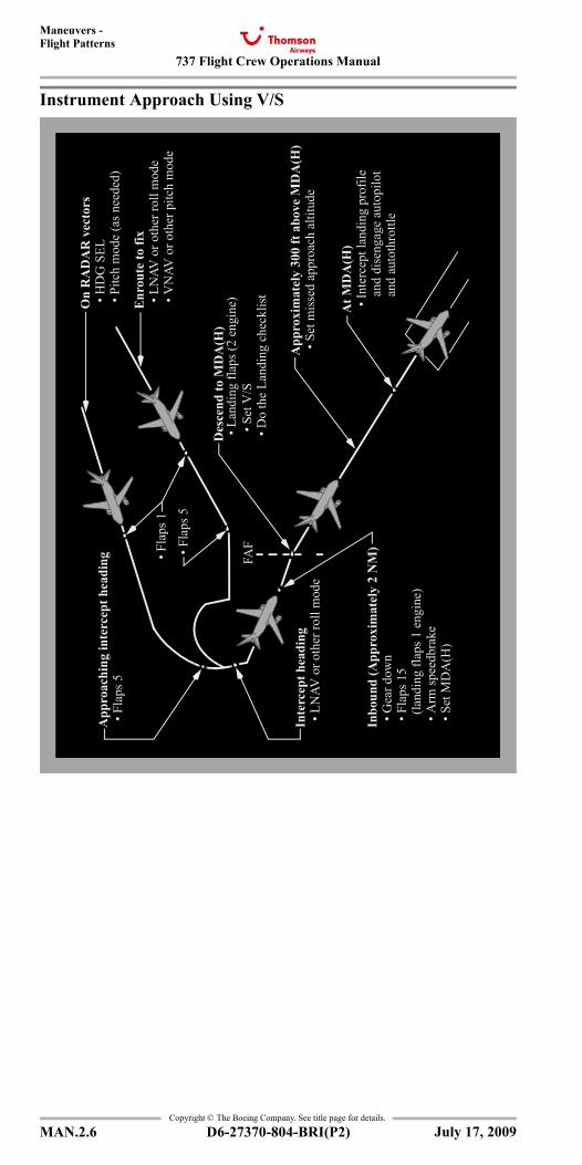
737 Flight Crew Operations Manual
Maneuvers -Flight Patterns
Copyright © The Boeing Company. See title page for details.
MAN.2.6 D6-27370-804-BRI(P2)
Instrument Approach Using V/S
App
roac
hing
inte
rcep
t hea
ding
• Fla
ps 5
• Fla
ps 1
• F
laps
5
Inte
rcep
t hea
ding
• L
NAV
or o
ther
roll
mod
e
Inbo
und
(App
roxi
mat
ely
2 N
M)
• G
ear d
own
• F
laps
15
(l
andi
ng fl
aps 1
eng
ine)
• A
rm sp
eedb
rake
• S
et M
DA
(H)
FAF
On
RA
DA
R v
ecto
rs •
HD
G S
EL •
Pitc
h m
ode
(as n
eede
d)
Enr
oute
to fi
x •
LN
AV o
r oth
er ro
ll m
ode
• V
NAV
or o
ther
pitc
h m
ode
Des
cend
to M
DA
(H)
• S
et V
/S •
Do
the
Land
ing
chec
klis
t
App
roxi
mat
ely
300
ft a
bove
MD
A(H
) •
Set
mis
sed
appr
oach
alti
tude
At M
DA
(H)
• In
terc
ept l
andi
ng p
rofil
e
and
dis
enga
ge a
utop
ilot
a
nd a
utot
hrot
tle
• L
andi
ng fl
aps (
2 en
gine
)
July 17, 2009
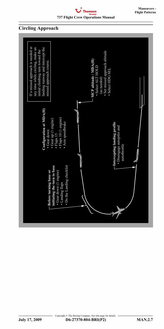
737 Flight Crew Operations Manual
Maneuvers -Flight Patterns
Copyright © The Boeing Company. See title page for details.
D6-27370-804-BRI(P2) MAN.2.7
Circling Approach
MC
P al
titud
e / M
DA
(H)
• S
elec
t ALT
HO
LD
(as n
eede
d) •
Set
mis
sed
appr
oach
alti
tude
• S
elec
t HD
G S
EL
If a
mis
sed
appr
oach
is n
eede
d at
any
time
whi
le c
irclin
g, m
ake
anin
itial
clim
bing
turn
tow
ard
the
land
ing
runw
ay a
nd in
terc
ept t
hem
isse
d ap
proa
ch c
ours
e.C
onfig
urat
ion
at M
DA
(H)
• G
ear d
own
• G
ear u
p (1
eng
ine)
• F
laps
15
• F
laps
10
(1 e
ngin
e) •
Arm
spee
dbra
ke
Bef
ore
turn
ing
base
or
• G
ear d
own
(1 e
ngin
e) •
Lan
ding
flap
s •
Do
the
Land
ing
chec
klis
t Inte
rcep
ting
land
ing
prof
ile •
Dis
enga
ge a
utop
ilot a
nd
aut
othr
ottle
initi
atin
g th
e tu
rn to
bas
e
July 17, 2009
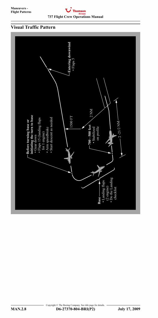
737 Flight Crew Operations Manual
Maneuvers -Flight Patterns
Copyright © The Boeing Company. See title page for details.
MAN.2.8 D6-27370-804-BRI(P2)
Visual Traffic Pattern •
Gea
r dow
n •
Fla
ps 1
5 (la
ndin
g fla
ps
for
1 e
ngin
e) •
Arm
spee
dbra
ke •
Sta
rt de
scen
t as n
eede
d
1500
FT 2
NM
2 -2
1/2
NM
Ent
erin
g do
wnw
ind
• F
laps
5
700
- 500
feet
• S
tabi
lized
on
prof
ileB
ase
• L
andi
ng fl
aps
(2
eng
ine)
• D
o th
e La
ndin
g
che
cklis
t
Bef
ore
turn
ing
base
or
initi
atin
g th
e tu
rn to
bas
e
July 17, 2009
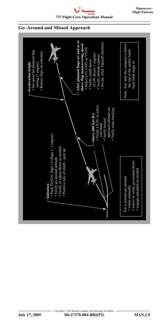
737 Flight Crew Operations Manual
Maneuvers -Flight Patterns
Copyright © The Boeing Company. See title page for details.
D6-27370-804-BRI(P2) MAN.2.9
Go–Around and Missed Approach
Aft
er p
lann
ed fl
aps s
et a
nd a
t or
abov
e fla
p m
aneu
veri
ng sp
eed
• S
elec
t LV
L C
HG
or V
NAV
• V
erify
clim
b th
rust
(
CO
N th
rust
, 1 e
ngin
e) •
Ver
ify a
ltitu
de c
aptu
re •
Do
the
Afte
r Tak
eoff
chec
klis
t
Abo
ve 4
00 fe
et R
A •
Ver
ify L
NAV
or s
elec
t
• V
erify
mis
sed
a
ppro
ach
altit
ude
set
• V
erify
rout
e tra
ckin
g
Acc
eler
atio
n he
ight
• S
et sp
eed
for p
lann
ed fl
ap
set
ting
(1 e
ngin
e) •
Ret
ract
flap
s on
sche
dule
Initi
atio
n •
Pus
h TO
/GA
, fla
ps 1
5 (f
laps
1, 1
eng
ine)
• V
erify
go-
arou
nd a
ttitu
de •
Ver
ify o
r adj
ust t
hrus
t as n
eede
d •
Pos
itive
rate
of c
limb
- gea
r up
For a
man
ual g
o-ar
ound
: •
rota
te m
anua
lly •
sele
ct o
r ver
ify g
o-ar
ound
thru
st •
eng
age
auto
pilo
t as n
eede
d
Not
e: A
ny ti
me
the
airs
peed
is b
elow
the
top
of th
e am
ber b
and,
lim
it ba
nk a
ngle
to 1
5°.
roll
mod
e
July 17, 2009
737 Flight Crew Operations Manual
Maneuvers -Flight Patterns
Copyright © The Boeing Company. See title page for details.
MAN.2.10 D6-27370-804-BRI(P2)
IntentionallyBlank
July 17, 2009
737 Flight Crew Operations Manual
Checklist Instructions Chapter CITable of Contents Section 0
Copyright © The Boeing Company. See title page for details.
D6-27370-804-BRI(P2) CI.TOC.0.1
Model Identification . . . . . . . . . . . . . . . . . . . . . . . . . . . . . . .CI.ModID
Revision Record . . . . . . . . . . . . . . . . . . . . . . . . . . . . . . . . . . . . . CI.RR
QRH List of Effective Pages . . . . . . . . . . . . . . . . . . . . . . . . . . CI.LEP
Normal Checklists . . . . . . . . . . . . . . . . . . . . . . . . . . . . . . . . . . . . . CI.1Introduction . . . . . . . . . . . . . . . . . . . . . . . . . . . . . . . . . . . . . . . . . . CI.1.1Normal Checklist Operation < BRI > . . . . . . . . . . . . . . . . . . . . . . CI.1.1Checklist Content. . . . . . . . . . . . . . . . . . . . . . . . . . . . . . . . . . . . . . CI.1.2Checklist Construction. . . . . . . . . . . . . . . . . . . . . . . . . . . . . . . . . . CI.1.3
Non-Normal Checklists . . . . . . . . . . . . . . . . . . . . . . . . . . . . . . . . . CI.2Introduction . . . . . . . . . . . . . . . . . . . . . . . . . . . . . . . . . . . . . . . . . . CI.2.1Non–Normal Checklist Operation < BRI > . . . . . . . . . . . . . . . . . . CI.2.1Non–Normal Checklist Use < BRI >. . . . . . . . . . . . . . . . . . . . . . . CI.2.3Non–Normal Checklist Use - Amplified < BRI > . . . . . . . . . . . . . CI.2.5Non–Normal Checklist Legend . . . . . . . . . . . . . . . . . . . . . . . . . . . CI.2.7
Redirection Symbol . . . . . . . . . . . . . . . . . . . . . . . . . . . . . . . . . CI.2.7Separator Symbol . . . . . . . . . . . . . . . . . . . . . . . . . . . . . . . . . . . CI.2.7Task Divider Symbol . . . . . . . . . . . . . . . . . . . . . . . . . . . . . . . . CI.2.7Decision Symbol. . . . . . . . . . . . . . . . . . . . . . . . . . . . . . . . . . . . CI.2.7Precaution Symbol . . . . . . . . . . . . . . . . . . . . . . . . . . . . . . . . . . CI.2.7
July 17, 2009
Checklist InstructionsTable of Contents
737 Flight Crew Operations Manual
Checklist Instructions -Table of Contents
Copyright © The Boeing Company. See title page for details.
CI.TOC.0.2 D6-27370-804-BRI(P2)
IntentionallyBlank
July 17, 2009
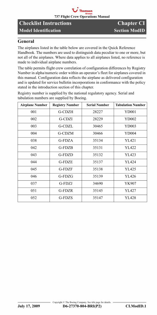
737 Flight Crew Operations Manual
Checklist Instructions Chapter CIModel Identification Section ModID
Copyright © The Boeing Company. See title page for details.
D6-27370-804-BRI(P2) CI.ModID.1
CI.ModID Checklist Instructions-Model IdentificationModel Identification
GeneralThe airplanes listed in the table below are covered in the Quick Reference Handbook. The numbers are used to distinguish data peculiar to one or more, but not all of the airplanes. Where data applies to all airplanes listed, no reference is made to individual airplane numbers.The table permits flight crew correlation of configuration differences by Registry Number in alpha/numeric order within an operator’s fleet for airplanes covered in this manual. Configuration data reflects the airplane as delivered configuration and is updated for service bulletin incorporations in conformance with the policy stated in the introduction section of this chapter.Registry number is supplied by the national regulatory agency. Serial and tabulation numbers are supplied by Boeing.
Airplane Number Registry Number Serial Number Tabulation Number
001 G-CDZH 28227 YD001
002 G-CDZI 28229 YD002
003 G-CDZL 30465 YD003
004 G-CDZM 30466 YD004
038 G-FDZA 35134 YL421
042 G-FDZB 35131 YL422
043 G-FDZD 35132 YL423
044 G-FDZE 35137 YL424
045 G-FDZF 35138 YL425
046 G-FDZG 35139 YL426
037 G-FDZJ 34690 YK907
051 G-FDZR 35145 YL427
052 G-FDZS 35147 YL428
July 17, 2009
Model Identification
737 Flight Crew Operations Manual
Checklist Instructions -Model Identification
Copyright © The Boeing Company. See title page for details.
CI.ModID.2 D6-27370-804-BRI(P2)
IntentionallyBlank
July 17, 2009
737 Flight Crew Operations Manual
Checklist Instructions Chapter CIRevision Record Section RR
Copyright © The Boeing Company. See title page for details.
D6-27370-804-BRI(P2) CI.RR.1
CI.RR Checklist Instructions-Revision RecordRevision Record
Revision Transmittal LetterTo: All holders of Thomson Airways 737 Flight Crew Operations Manual, Boeing Document Number D6-27370-804-BRI(P2).Subject: Flight Crew Operations Manual Revision.This revision reflects the most current information available to The Boeing Company 45 days before the subject revision date. The following revision highlights explain changes in this revision. General information below explains the use of revision bars to identify new or revised information.
Revision Record
GeneralThe Boeing Company issues flight crew operations manual revisions to provide new or revised procedures and information. Formal revisions also incorporate appropriate information from previously issued flight crew operations manual bulletins.The revision date is the approximate date the manual is mailed to the customer.Formal revisions include a Transmittal Letter, a new Revision Record, Revision Highlights, and a current List of Effective Pages. Use the information on the new Revision Record and List of Effective Pages to verify the manual content.Pages containing revised technical material have revision bars associated with the changed text or illustration. Editorial revisions (for example, spelling corrections) may have revision bars with no associated highlight.The record above should be completed by the person incorporating the revision into the manual.
Filing InstructionsConsult the List of Effective Pages (CI.LEP). Pages identified with an asterisk (*) are either replacement pages or new (original) issue pages. Remove corresponding old pages and replace or add new pages. Remove pages that are marked DELETED; there are no replacement pages for deleted pages.
Revision HighlightsThis section (CI.RR) replaces the existing section CI.RR in your manual.Be careful when inserting changes not to throw away pages from the manual that are not replaced. Using the List of Effective Pages (CI.LEP) can help determine the correct content of the manual.Throughout the manual, airplane effectivity may be updated to reflect coverage as listed on the Preface - Model Identification page, or to show service bulletin airplane effectivity. Highlights are not supplied.
No. Revision Date Date Filed
No. Revision Date Date Filed
0 July 17, 2009
July 17, 2009
Revision Record
737 Flight Crew Operations Manual
Checklist Instructions -Revision Record
Copyright © The Boeing Company. See title page for details.
CI.RR.2 D6-27370-804-BRI(P2)
This manual is published from a database; the text and illustrations are marked with configuration information. Occasionally, because the editors rearrange the database markers, or mark items with configuration information due to the addition of new database content, some customers may receive revision bars on content that appears to be unchanged. Pages may also be republished without revision bars due to slight changes in the flow of the document.
July 17, 2009
737 Flight Crew Operations Manual
Checklist InstructionsQRH List of Effective Pages
Chapter CISection LEP
* = Revised, Added, or DeletedCopyright © The Boeing Company. See title page for details.
D6-27370-804-BRI(P2) CI.LEP.1
CI.LEP Checklist Instructions-QRH List of Effec-tive PagesQRH List of Effective PagesQRH List of Effective Pages
Page Date
Quick Reference Handbook
Quick Action Index
* QA.Index.1-2 July 17, 2009
Lights (tab)
* Lights.Index.1-6 July 17, 2009
Unannunciated (tab)
* Unann.Index.1-2 July 17, 2009
Alphabetical (tab)
* Alpha.Index.1-8 July 17, 2009
Normal Checklists
* NC.1-4 July 17, 2009
0 Miscellaneous (tab)
* 0.TOC.1-2 July 17, 2009
* 0.1-12 July 17, 2009
1 Airplane General, Emergency Equipment, Doors, Windows (tab)
* 1.TOC.1-2 July 17, 2009
* 1.1-12 July 17, 2009
2 Air Systems (tab)
* 2.TOC.1-2 July 17, 2009
* 2.1-14 July 17, 2009
3 Anti-Ice, Rain (tab)
* 3.TOC.1-2 July 17, 2009
* 3.1-4 July 17, 2009
4 Automatic Flight (tab)
* 4.TOC.1-2 July 17, 2009
* 4.1-2 July 17, 2009
5 Communications (tab)
* 5.TOC.1-2 July 17, 2009
* 5.1-2 July 17, 2009
6 Electrical (tab)
* 6.TOC.1-2 July 17, 2009
* 6.1-8 July 17, 2009
7 Engines, APU (tab)
* 7.TOC.1-2 July 17, 2009
* 7.1-28 July 17, 2009
8 Fire Protection (tab)
* 8.TOC.1-2 July 17, 2009
* 8.1-18 July 17, 2009
9 Flight Controls (tab)
* 9.TOC.1-2 July 17, 2009
* 9.1-30 July 17, 2009
10 Flight Instruments, Displays (tab)
* 10.TOC.1-2 July 17, 2009
* 10.1-6 July 17, 2009
11 Flight Management, Navigation (tab)
* 11.TOC.1-2 July 17, 2009
* 11.1-14 July 17, 2009
12 Fuel (tab)
* 12.TOC.1-2 July 17, 2009
* 12.1-12 July 17, 2009
13 Hydraulics (tab)
* 13.TOC.1-2 July 17, 2009
* 13.1-14 July 17, 2009
14 Landing Gear (tab)
* 14.TOC.1-2 July 17, 2009
* 14.1-16 July 17, 2009
15 Warning Systems (tab)
* 15.TOC.1-2 July 17, 2009
* 15.1-6 July 17, 2009
Ops Info (tab)
* OI.TOC.1-2 July 17, 2009
* OI.1.1-2 July 17, 2009
* OI.2.1-4 July 17, 2009
* OI.3.1-4 July 17, 2009
* OI.4.1-2 July 17, 2009
* OI.5.1-2 July 17, 2009
* OI.6.1-2 July 17, 2009
* OI.7.1-2 July 17, 2009
* OI.8.1-2 July 17, 2009
Performance - Inflight (tab)
* PI-QRH.TOC.1-2 July 17, 2009
* PI-QRH.TOC.10.1-2 July 17, 2009
* PI-QRH.10.1-4 July 17, 2009
* PI-QRH.11.1-12 July 17, 2009
* PI-QRH.12.1-10 July 17, 2009
* PI-QRH.13.1-4 July 17, 2009
* PI-QRH.14.1-4 July 17, 2009
Page Date
July 17, 2009
QRH List of Effective Pages
737 Flight Crew Operations Manual
Checklist Instructions -QRH List of Effective Pages
* = Revised, Added, or DeletedCopyright © The Boeing Company. See title page for details.
CI.LEP.2 D6-27370-804-BRI(P2)
Performance - Inflight (cont)
* PI-QRH.15.1-4 July 17, 2009
* PI-QRH.TOC.20.1-2 July 17, 2009
* PI-QRH.20.1-4 July 17, 2009
* PI-QRH.21.1-12 July 17, 2009
* PI-QRH.22.1-10 July 17, 2009
* PI-QRH.23.1-4 July 17, 2009
* PI-QRH.24.1-4 July 17, 2009
* PI-QRH.25.1-4 July 17, 2009
Maneuvers (tab)
* Man.TOC.0.1-2 July 17, 2009
* MAN.05.1-2 July 17, 2009
* MAN.1.1-10 July 17, 2009
* MAN.2.1-10 July 17, 2009
Checklist Instructions (tab)
* CI.TOC.0.1-2 July 17, 2009
* CI.ModID.1-2 July 17, 2009
* CI.RR.1-2 July 17, 2009
* CI.LEP.1-2 July 17, 2009
* CI.1.1-4 July 17, 2009
* CI.2.1-8 July 17, 2009
Evacuation (tab)
* Back Cover.1-2 July 17, 2009
Page Date
July 17, 2009
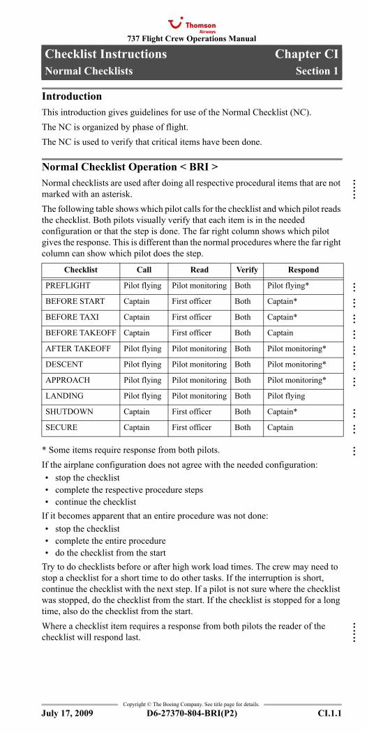
737 Flight Crew Operations Manual
Checklist Instructions Chapter CINormal Checklists Section 1
Copyright © The Boeing Company. See title page for details.
D6-27370-804-BRI(P2) CI.1.1
CI.1 Checklist Instructions-Normal ChecklistsNormal ChecklistsNormal Checklists
IntroductionThis introduction gives guidelines for use of the Normal Checklist (NC).The NC is organized by phase of flight. The NC is used to verify that critical items have been done.
Normal Checklist Operation < BRI >Normal checklists are used after doing all respective procedural items that are not marked with an asterisk.The following table shows which pilot calls for the checklist and which pilot reads the checklist. Both pilots visually verify that each item is in the needed configuration or that the step is done. The far right column shows which pilot gives the response. This is different than the normal procedures where the far right column can show which pilot does the step.
* Some items require response from both pilots.If the airplane configuration does not agree with the needed configuration:• stop the checklist• complete the respective procedure steps• continue the checklist
If it becomes apparent that an entire procedure was not done:• stop the checklist• complete the entire procedure• do the checklist from the start
Try to do checklists before or after high work load times. The crew may need to stop a checklist for a short time to do other tasks. If the interruption is short, continue the checklist with the next step. If a pilot is not sure where the checklist was stopped, do the checklist from the start. If the checklist is stopped for a long time, also do the checklist from the start.Where a checklist item requires a response from both pilots the reader of the checklist will respond last.
Checklist Call Read Verify Respond
PREFLIGHT Pilot flying Pilot monitoring Both Pilot flying*
BEFORE START Captain First officer Both Captain*
BEFORE TAXI Captain First officer Both Captain*
BEFORE TAKEOFF Captain First officer Both Captain
AFTER TAKEOFF Pilot flying Pilot monitoring Both Pilot monitoring*
DESCENT Pilot flying Pilot monitoring Both Pilot monitoring*
APPROACH Pilot flying Pilot monitoring Both Pilot monitoring*
LANDING Pilot flying Pilot monitoring Both Pilot flying
SHUTDOWN Captain First officer Both Captain*
SECURE Captain First officer Both Captain
July 17, 2009
:::
::::::::::::::::::::::
::::::
:::
737 Flight Crew Operations Manual
Checklist Instructions -Normal Checklists
Copyright © The Boeing Company. See title page for details.
CI.1.2 D6-27370-804-BRI(P2)
The BEFORE START checklist may be initiated before the flight deck door is closed and anti-collision light is turned ON by calling "BEFORE START CHECKLIST ABOVE THE LINE". Once all remaining items have been accomplished the checklist should be completed by calling "BEFORE START CHECKLIST BELOW THE LINE". If the checklist is initiated after all items have been accomplished call "BEFORE START CHECKLIST".Whilst it is acceptable for PF to call "GEAR DOWN, FLAPS___, LANDING CHECKLIST", PM should only begin the LANDING checklist once the gear is down.Checklists that contain responses marked with an asterisk may be initiated prior to the final checklist item being accomplished. In these cases, when reaching the final checklist item, the reader should announce the final item and the response should be "TO COME", e.g. when accomplishing the landing checklist the PM announces "FLAPS" and the PF will respond "TO COME". The PM will then state "FLAPS ___ WILL COMPLETE THE LANDING CHECKLIST". When the flaps have reached the landing position the PM should announce "FLAPS" and the PF will respond accordingly.Do not stow the checklist until all items are complete.In the PREFLIGHT checklist the item "Flight instruments" is a prompt to check the ND heading indication and the primary altimeters sub setting and altitude indication for RVSM compliance. Example response: "HEADING 232, ALTIMETER 1004, 280 FEET"When the QNH has been set, the PF will request the APPROACH checklist. The item "NAV aids" is a prompt to check the radio aids and the courses are set appropriate to the stage of flight. It is not necessary for the NAV aids to be set for final approach to complete the checklist.When the landing gear has been selected DOWN, PF will normally request the LANDING checklist, provided the cabin is secure and the speedbrake lever is armed. PM will set the ENGINE START SWITCHES to CONT, and read the LANDING checklist once the gear is down.The "stick checklist" provided on the control column is not subject to revision and must not be used.After completion of each checklist, the pilot reading the checklist calls, "___ CHECKLIST COMPLETE."
Checklist ContentThe checklist has the minimum items needed to operate the airplane safely.Normal checklists have items that meet any of the following criteria:• items essential to safety of flight that are not monitored by an alerting
system, or• items essential to safety of flight that are monitored by an alerting system
but if not done, would likely result in a catastrophic event if the alerting system fails, or
• items needed to meet regulatory requirements, or• items needed to maintain fleet commonality between the 737, 747-400,
757, 767, 777, and 787, or• items that enhance safety of flight and are not monitored by an alerting
system (for example the autobrake), or• during shutdown and secure, items that could result in injury to personnel
or damage to equipment if not done.
July 17, 2009
:::::::::::::::::::::::::::
:
::::::::::::::::::::::::::
737 Flight Crew Operations Manual
Checklist Instructions -Normal Checklists
Copyright © The Boeing Company. See title page for details.
D6-27370-804-BRI(P2) CI.1.3
Checklist ConstructionWhen a checklist challenge does not end with “switch or lever”, then the challenge refers to system status. For example, “Landing Gear...Down”, refers to the status of the landing gear, not just the position of the lever.When a checklist challenge ends with “switch or lever”, then the challenge refers to the position of the switch or lever. For example, “Engine start levers...CUTOFF” refers to the position of the levers.
July 17, 2009
737 Flight Crew Operations Manual
Checklist Instructions -Normal Checklists
Copyright © The Boeing Company. See title page for details.
CI.1.4 D6-27370-804-BRI(P2)
IntentionallyBlank
July 17, 2009
737 Flight Crew Operations Manual
Checklist Instructions Chapter CINon-Normal Checklists Section 2
Copyright © The Boeing Company. See title page for details.
D6-27370-804-BRI(P2) CI.2.1
CI.2 Checklist Instructions-Non-Normal ChecklistsNon-Normal ChecklistsNon-Normal Checklists
IntroductionThe non-normal checklists chapter contains checklists used by the flight crew to manage non–normal situations. The checklists are grouped in sections which match the system description chapters in Volume 2. Most checklists correspond to a light, alert or other indication. In most cases, the MASTER CAUTION and system annunciator lights also illuminate to indicate the non-normal condition. These lights, alerts and other indications are the cues to select and do the associated checklist.Checklists without a light, alert or other indication (such as Ditching) are called unannunciated checklists. Most unannunciated checklists are in the associated system section. For example, Engine Fuel Leak is in section 12, Fuel. Unannunciated checklists with no associated system are in section 0, Miscellaneous.All checklists have condition statements. The condition statement briefly describes the situation that caused the light, alert or other indication. Unannunciated checklists also have condition statements to help in understanding the reason for the checklist.Some checklists have objective statements. The objective statement briefly describes the expected result of doing the checklist or briefly describes the reason for steps in the checklist.Checklists can have both memory and reference items. Memory items are critical steps that must be done before reading the checklist. The last memory item is followed by a dashed horizontal line. Reference items are actions to be done while reading the checklist.
Some checklists have additional information at the end of the checklist. The additional information provides data the crew may wish to consider. The additional information does not need to be read.Checklists that need a quick response are listed in the Quick Action Index. In each system section, Quick Action Index checklists are listed first, followed by checklists that are not in the Quick Action Index. The titles of Quick Action Index checklists are printed in bold type. Checklist titles in upper case (such as AUTO BRAKE DISARM) are annunciated by a light, alert, or other indication. Checklist titles in upper and lower case (such as Window Damage) are not annunciated.
Non–Normal Checklist Operation < BRI >Non–normal checklists start with steps to correct the situation. If needed, information for planning the rest of the flight is included. When special items are needed to configure the airplane for landing, the items are included in the Deferred Items section of the checklist. Flight patterns for some non–normal situations are located in the Maneuvers chapter and show the sequence of configuration changes.While every attempt is made to supply needed non–normal checklists, it is not possible to develop checklists for all conceivable situations. In some smoke, fire or fumes situations, the flight crew may need to move between the Smoke, Fire or Fumes checklist and the Smoke or Fumes Removal checklist. In some multiple failure situations, the flight crew may need to combine the elements of more than one checklist. In all situations, the captain must assess the situation and use good judgment to determine the safest course of action.
July 17, 2009
737 Flight Crew Operations Manual
Checklist Instructions -Non-Normal Checklists
Copyright © The Boeing Company. See title page for details.
CI.2.2 D6-27370-804-BRI(P2)
There are some situations where the flight crew must land at the nearest suitable airport. These situations include, but are not limited to, conditions where:• the non–normal checklist includes the item “Plan to land at the nearest
suitable airport.”• fire or smoke continues• only one AC power source remains (engine or APU generator)• only one hydraulic system remains (the standby system is considered a
hydraulic system)• any other situation determined by the flight crew to have a significant
adverse effect on safety if the flight is continued.It must be stressed that for smoke that continues or a fire that cannot be positively confirmed to be completely extinguished, the earliest possible descent, landing, and evacuation must be done.If a smoke, fire or fumes situation becomes uncontrollable, the flight crew should consider an immediate landing. Immediate landing implies immediate diversion to a runway. However, in a severe situation, the flight crew should consider an overweight landing, a tailwind landing, an off-airport landing, or a ditching.Checklists directing an engine shutdown must be evaluated by the captain to determine whether an actual shutdown or operation at reduced thrust is the safest course of action. Consideration must be given to the probable effects of running the engine at reduced thrust.There are no non–normal checklists for the loss of an engine indication or automatic display of the secondary engine indications. Continue normal engine operation unless a limit is exceeded.Non–normal checklists also assume:• During engine start and before dispatch, the associated non–normal
checklist is done if a non-normal situation is identified. After completion of the checklist, the MEL must be consulted to determine if dispatch relief is available.
• After dispatch and before takeoff, the associated non-normal checklist is done if a non-normal situation is identified. After completion of the checklist the MEL is consulted to determine if dispatch relief is available for subsequent sectors.
• System controls are in the normal configuration for the phase of flight before the start of the non–normal checklist.
• If the MASTER CAUTION and system annunciator lights illuminate, all related amber lights are reviewed to assist in recognizing the cause(s) of the alert.
• Aural alerts are silenced and the master caution system is reset by the flight crew as soon as the cause of the alert is recognized.
• The EMERGENCY position of the oxygen regulator is used when needed to supply positive pressure in the masks and goggles to remove contaminants. The 100% position of the oxygen regulator is used when positive pressure is not needed but contamination of the flight deck air exists. The Normal position of the oxygen regulator is used if prolonged use is needed and the situation allows. Normal boom microphone operation is restored when oxygen is no longer in use.
• Indicator lights are tested to verify suspected faults.
July 17, 2009
::::::::::::
737 Flight Crew Operations Manual
Checklist Instructions -Non-Normal Checklists
Copyright © The Boeing Company. See title page for details.
D6-27370-804-BRI(P2) CI.2.3
• In flight, reset of a tripped circuit breaker is not recommended unless directed by a non-normal checklist. However, a tripped circuit breaker may be reset once, after a short cooling period (approximately 2 minutes), if in the judgment of the captain, the situation resulting from the circuit breaker trip has a significant adverse effect on safety. On the ground, flight crew reset of a tripped circuit breaker should only be done after maintenance has determined that it is safe to reset the circuit breaker.
• Flight crew cycling (pulling and resetting) of a circuit breaker to clear a non-normal condition is not recommended, unless directed by a non-normal checklist.
After engine start and before takeoff, illumination of a red warning light, an amber caution light, an alert or other indication requires completion of the associated checklist. In certain cases, amber system monitor lights illuminate during MASTER CAUTION recall to inform the flight crew of the failure of one element in a system with redundant elements. If system operation is maintained by a second element, the amber system monitor light will extinguish when MASTER CAUTION is reset. In these situations, the amber light alerts the flight crew that normal system operation will be affected if another element fails. If an amber light illuminates during MASTER CAUTION recall, but extinguishes after MASTER CAUTION reset, completion of the associated checklist is not required.
Non–Normal Checklist Use < BRI >If a checklist or a step in a checklist is not applicable to all airplanes, airplane effectivity information is included in the checklist. Airplane effectivity can be listed by airplane number, registry number, serial number or tabulation number. If a checklist is applicable to some but not all airplanes, airplane effectivity is centered below the checklist title. If a step in a checklist is applicable to some but not all airplanes, airplane effectivity is included above the step. If a checklist or a step in a checklist is applicable to all airplanes, airplane effectivity information is not included.Non–normal checklist use starts when the airplane flight path and configuration are correctly established. Only a few situations need an immediate response (such as CABIN ALTITUDE WARNING or Rapid Depressurization). Usually, time is available to assess the situation before corrective action is started. All actions must then be coordinated under the captain's supervision and done in a deliberate, systematic manner. Flight path control must never be compromised.When a non–normal situation occurs in the air, at the direction of the pilot flying, both crewmembers do all memory items in their areas of responsibility without delay.On the ground, the captain will act as pilot flying for all non-normal situations.The pilot flying calls for the checklist when:• the flight path is under control• the airplane is not in a critical phase of flight (such as takeoff or landing)• all memory items are complete.
The pilot monitoring reads aloud:• the checklist title• as much of the condition statement as needed to verify that the correct
checklist has been selected• as much of the objective statement (if applicable) as needed to understand
the expected result of doing the checklist.The pilot flying does not need to repeat this information but must acknowledge that the information was heard and understood.
July 17, 2009
:::::::
737 Flight Crew Operations Manual
Checklist Instructions -Non-Normal Checklists
Copyright © The Boeing Company. See title page for details.
CI.2.4 D6-27370-804-BRI(P2)
For checklists with memory items, the pilot monitoring first verifies that each memory item has been done. The checklist is normally read aloud during this verification. The pilot flying does not need to respond except for items that are not in agreement with the checklist. The item numbers do not need to be read.Non-memory items are called reference items. The pilot monitoring reads aloud the reference items, including:• the precaution (if any)• the response or action• any amplifying information.
The pilot flying does not need to repeat this information but must acknowledge that the information was heard and understood. The item numbers do not need to be read.The word “Confirm” is added to checklist items when both crewmembers must verbally agree before action is taken. During an inflight non-normal situation, verbal confirmation is required for:• an engine thrust lever• an engine start lever• an engine, APU or cargo fire switch• a generator drive disconnect switch• an IRS mode selector, when only one IRS is failed• a flight control switch
This does not apply to the EMERGENCY DESCENT or LOSS OF THRUST ON BOTH ENGINES checklist.With the airplane on the ground:• the captain and the first officer take action based on preflight and
postflight areas of responsibility• during an evacuation, the first officer sets the flap lever to 40.
With the airplane in flight:• the pilot flying and the pilot monitoring take action based on each
crewmember’s Areas of Responsibility.The engine thrust levers are considered to be in the pilot flying’s area of responsibility in the air, and the captain’s area of responsibility on the ground. The engine start levers and all fire switches are considered to be in the pilot monitoring’s area of responsibility in the air and the first officer’s area of responsibility on the ground.On the ground, the parking brake and speedbrake lever are in the captain’s area of responsibility.After moving the control, the crewmember taking the action also states the checklist response.The pilot flying may also direct reference checklists to be done by memory if no hazard is created by such action, or if the situation does not allow reference to the checklist.Checklists include an Inoperative Items table only when the condition of the items is needed for planning the rest of the flight. The inoperative items, including the consequences (if any), are read aloud by the pilot monitoring. The pilot flying does not need to repeat this information but must acknowledge that the information was heard and understood.After completion of the non–normal checklist, normal procedures are used to configure the airplane for each phase of flight.When there are no deferred items, the DESCENT, APPROACH and LANDING normal checklists are used to verify that the configuration is correct for each phase of flight.
July 17, 2009
:::::
::
:::::::::::
737 Flight Crew Operations Manual
Checklist Instructions -Non-Normal Checklists
Copyright © The Boeing Company. See title page for details.
D6-27370-804-BRI(P2) CI.2.5
When there are deferred items, the non-normal checklist will include the item “Checklist Complete Except Deferred Items.” The pilot flying is to be made aware when there are deferred items. These items are included in the Deferred Items section of the checklist and may be delayed until the usual point during descent, approach or landing.The deferred items are read aloud by the pilot monitoring. The pilot flying or the pilot monitoring takes action based on each crewmember’s area of responsibility. After moving the control, the crewmember taking the action also states the response.When there are deferred items, the Deferred Items section of the non-normal checklist will include the Descent, Approach and Landing normal checklists. These checklists should be used instead of the usual DESCENT, APPROACH and LANDING normal checklists. If a normal checklist item is changed as a result of the non-normal situation, the changed response is printed in bold type. The pilot flying or the pilot monitoring responds to the deferred normal checklist items based on each crewmember’s area of responsibility. However, during the deferred Landing normal checklist, the pilot flying responds to all deferred normal checklist items.Each checklist has a checklist complete symbol at the end. The following symbol indicates that the checklist is complete:
The checklist complete symbol can also be in the body of the checklist. This only occurs when a checklist divides into two or more paths. Each path can have a checklist complete symbol at the end. The flight crew does not need to continue reading the checklist after the checklist complete symbol.After completion of each non–normal checklist, the pilot monitoring states “___ CHECKLIST COMPLETE.”Additional information at the end of the checklist is not required to be read.The flight crew must be aware that checklists cannot be created for all conceivable situations and are not intended to replace good judgment. In some situations, at the captain’s discretion, deviation from a checklist may be needed.
Non–Normal Checklist Use - Amplified < BRI >The first pilot to recognize any non-normal condition must call it out clearly and precisely. Review all caution and warning lights to positively identify the non-normal condition. The relevant checklist should be accomplished only after the non-normal condition has been positively identified.On the ground, the captain will call for memory items, as appropriate, and the relevant checklist. The first officer will read the checklist.In the air, the pilot flying will call for memory items, as appropriate, and the relevant checklist. The pilot monitoring will read the checklist.In the event of an aborted engine start the first officer must complete the memory item without delay. Subsequently the captain will call for the relevant checklist which the first officer will read. In the event of an engine failing to start seek engineering advice and, if appropriate, consult the MEL prior to attempting a subsequent start.
July 17, 2009
::::::::::::::::::::::::
:
737 Flight Crew Operations Manual
Checklist Instructions -Non-Normal Checklists
Copyright © The Boeing Company. See title page for details.
CI.2.6 D6-27370-804-BRI(P2)
Whenever an emergency exists on the ground that is considered life threatening to persons on board, the EVACUATION checklist should be performed without delay; this may require other checklists to be discontinued at any point. Captains should use all available sources of information when determining if an evacuation is necessary and be aware that it is likely that one or more persons may be injured in an evacuation. If an Evacuation is needed the captain will assume the role of pilot flying, stop the aircraft and set the Parking Brake. The captain will call "EVACUATION CHECKLIST".In the event of an evacuation, the First Officer will select/confirm FLAP lever 40 and then read the EVACUATION checklist. The parking brake and speedbrake lever will be actioned by the captain. The captain will state the checklist response for these items.Inflight, when a non-normal checklist requires the autothrottle to be disengaged, this should normally be accomplished by the pilot flying.Inflight, when a non-normal checklist requires a thrust lever to be moved, either as a memory or reference item, this should normally be accomplished by the pilot flying. The pilot flying must verbally confirm the affected thrust lever with pilot monitoring prior to action being taken. When actioning the EMERGENCY DESCENT, or LOSS OF THRUST ON BOTH ENGINES checklists, it is not necessary to verbally confirm the affected thrust levers with pilot monitoring prior to action being taken. The pilot flying slowly retards the affected thrust lever. When the thrust lever item is complete, the pilot flying will state the checklist response.Inflight, when an engine shutdown is required, pilot monitoring places a hand on and verbally identifies the start lever for the engine to be shutdown. The start lever must only be actioned after verbal confirmation from the pilot flying.Inflight, when activation of any fire switch is required, pilot monitoring places a hand on and verbally identifies the affected fire switch. The fire switch must only be actioned after verbal confirmation from the pilot flying.In the event of an engine malfunction at or above V1, the takeoff should be continued. Pilot monitoring will call the malfunction using the terms "Engine Failure" or "Engine Fire" as appropriate, without specifying which engine. If additional climb performance is required on a derated thrust and/or assumed temperature reduced thrust take-off, the thrust lever of the operating engine may be advanced to full rated thrust, provided the aircraft is airborne, the IAS is V2 or greater, and no directional control difficulties are encountered. This guidance will ensure protection against minimum control speed.Confirmation of which engine has failed and the nature of the failure will be completed at a safe height (minimum 400’ AGL), followed by memory items as appropriate. When the flaps have been retracted the appropriate non-normal checklist will be completed, followed by the After Takeoff checklist.An engine failure procedure is produced for all runways and requires either climbing straight ahead or an Emergency Turn. When an engine failure procedure involves a deviation from the SID, ATC must be informed.When an emergency turn is required, the flaps should be retracted when:• All close in and radius limited turns are completed, and• At or above single engine minimum flap retraction altitude.
If the intermittent warning horn sounds inflight above 10,000 feet, both pilots will immediately don oxygen masks. Both pilots must verify on the overhead CabinAltitude Panel that the cabin altitude is stabilized at or below 10,000 feet beforeremoving oxygen masks.
July 17, 2009
::::::::::::::::::::::::::::::::
:::::::::::::::::::::::::::::::::::
:
:
:
:
:
:
:::
::::::::::::
737 Flight Crew Operations Manual
Checklist Instructions -Non-Normal Checklists
Copyright © The Boeing Company. See title page for details.
D6-27370-804-BRI(P2) CI.2.7
Non–Normal Checklist Legend
Redirection Symbol
The redirection symbol is used in two ways:• In the Table of Contents of a system section, to direct the flight crew to a
different system section.• In a non-normal checklist, with the word “Go to”, to direct the flight crew
to a different checklist or to a different step in the current checklist.
Separator Symbol
The separator symbol is used in two ways:• In the Table of Contents of a system section, to separate the Quick Action
Index checklists from the checklists that are not in the Quick Action Index.
• In a non-normal checklist, to separate the memory items from the reference items.
Task Divider Symbol
The task divider symbol is used to indicate the end of one task and the beginning of another task.
Decision Symbol Choose one:
The decision symbol is used to identify possible choices.
Precaution Symbol
The precaution symbol is used to identify information the flight crew must consider before taking the action.
July 17, 2009
737 Flight Crew Operations Manual
Checklist Instructions -Non-Normal Checklists
Copyright © The Boeing Company. See title page for details.
CI.2.8 D6-27370-804-BRI(P2)
IntentionallyBlank
July 17, 2009
737 Flight Crew Operations Manual Back Cover.1
Copyright © The Boeing Company. See title page for details.
D6-27370-804-BRI(P2) Back Cover.1
Back Cover.Back Cover Non-Normal Checklists-Evacuation ChecklistEvacuation
Evacuation Checklist is on the reverse side of this page.
July 17, 2009
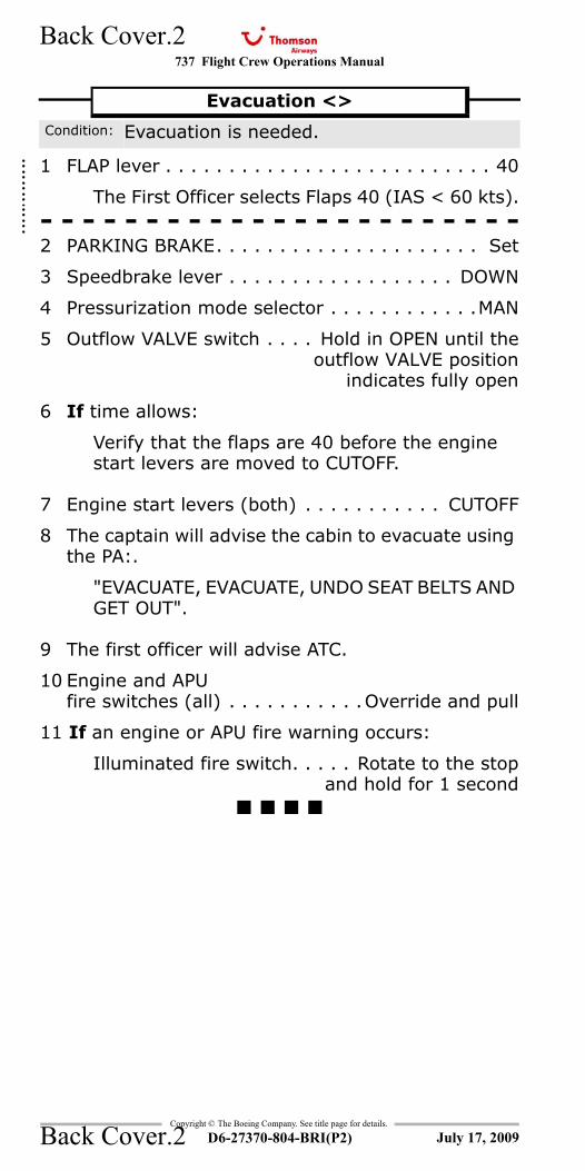
737 Flight Crew Operations Manual
Copyright © The Boeing Company. See title page for details.
D6-27370-804-BRI(P2)
Back Cover.2
Back Cover.2
1 FLAP lever . . . . . . . . . . . . . . . . . . . . . . . . . . 40
The First Officer selects Flaps 40 (IAS < 60 kts).- - - - - - - - - - - - - - - - - - - - - - -2 PARKING BRAKE. . . . . . . . . . . . . . . . . . . . . Set
3 Speedbrake lever . . . . . . . . . . . . . . . . . . DOWN
4 Pressurization mode selector . . . . . . . . . . . .MAN
5 Outflow VALVE switch . . . . Hold in OPEN until theoutflow VALVE position
indicates fully open
6 If time allows:
Verify that the flaps are 40 before the engine start levers are moved to CUTOFF.
7 Engine start levers (both) . . . . . . . . . . . CUTOFF
8 The captain will advise the cabin to evacuate using the PA:.
"EVACUATE, EVACUATE, UNDO SEAT BELTS AND GET OUT".
9 The first officer will advise ATC.
10 Engine and APUfire switches (all) . . . . . . . . . . .Override and pull
11 If an engine or APU fire warning occurs:
Illuminated fire switch. . . . . Rotate to the stopand hold for 1 second
Evacuation <>
Condition: Evacuation is needed.
July 17, 2009
::::::::
Recommended