1
Pyroclastic flow mitigation strategies: a new perspective
for the red area Mauro Iacuaniello1, Andrea Montanino1, Daniela De Gregorio2, Giulio Zuccaro1,2
1Department of Structures for Engineering and Architecture, University of Naples, Naples, Italy 2) PLINIVS - LUPT Study Centre, University of Naples Federico II, Via Toledo 402, 80134, Naples, Italy 5
Correspondence to Mauro Iacuaniello ([email protected])
Abstract.
This paper intends to show basic strategies and technical solutions that may reduce the consequence of a volcanic eruption
on buildings. One of the most dangerous eruptive phenomena is pyroclastic flow, a gas-solid mixture which can flow slope
down up to reach considerable distances from the point of emission, with a speed that can easily exceed 100km/h (~ 30m/s). 10
The damage caused by the impact on buildings depends on the combination of several factors: the duration of phenomenon,
the temperature of flow and the pressure produced by the impact. The study tries to define a design-oriented approach of
retrofitting and new construction with specific reference to the possible eruption of Vesuvio or Campi Flegrei in the
Campania Region of Italy. For both red areas, which are directly affected by the flows, the Department of Civil Protection
defined only one solution, that is the preventive evacuation. Whilst through the proposed mitigation strategy, the task is to 15
establish a resilient sector within the red areas where buildings can withstand pressure and temperature in order to achieve
both economic benefits and make reconstruction easier.
Keywords: Mitigation strategies; Volcanic risk; Pyroclastic flows.
20
1.Introduction
Explosive volcanic eruptions have the potential to cause casualties and economic losses, unless appropriate mitigation
measures can be taken. Inside the metropolitan area surrounding the city of Naples (Campania Region, Italy) there are two
active volcanic systems, the Somma-Vesuvius and the Campi Flegrei, whose geological history allows to believe that they
will be able to produce, in the future, some explosive eruptions. The hazard of both volcanoes, the high exposed value of 25
urban area, which counts about three thousand people, and the high vulnerability of the urban settlements make the
Neapolitan territory one of the riskiest volcanic area in the word (Zuccaro and De Gregorio, 2011). Volcanic eruptions
encompass different hazards as volcanic earthquake, ash fall, pyroclastic flows and subsequent floods and mudflows. The
most dangerous phenomenon is the pyroclastic flows, which can occur with little warning, move at high speeds, and have
enormous destructive power (Spence et al., 2010). Although the Emergency Plans provide for the preventive evacuation of 30
the areas affected by the phenomenon, the protection of the openings represents the main objective as it happened during the
https://doi.org/10.5194/nhess-2020-320Preprint. Discussion started: 22 October 2020c© Author(s) 2020. CC BY 4.0 License.
2
volcanic eruption on the Caribbean island of Montserrat (British Overseas Territory), the openings and especially the
unprotected ones were the first elements of the building envelope to be compromised and causing considerable damage to
the structure itself. Therefore, in this paper, the vulnerability analysis of these elements present in the Neapolitan areas and
the analysis of mitigation strategies valid for both pressures and temperatures have been carried out first. Through these 35
analyses, it is possible to define within the red areas possible resilient sectors in which the recovery of buildings could have
both economic and technical feasibility advantages.
2.Volcanic Phenomena
Explosive eruptions, foreseen in Vesuvius and Campi Flegrei regions, are characterized by a powerful ejection of pyroclastic 40
material producing the eruptive column composed of gas-solid dispersal, which rises vertically from the eruptive centre and
extending alongside the wind action, which disperses the haze according to its own direction. Hence, part of clasts falls from
the column into gas-solid dispersals designated as pyroclastic flows and surges, respectively, with a high or low density of
particles; the rest of the clasts descends via gravity (ash fall deposits) or is exploded directly in the air from the crater
(ballistics). Furthermore, the eruption process involves seismic shakings plus trembles, (produced by the cracking of rocks 45
compressed by the magma motion); landslides, floods and lahars (flows of water mixed to pyroclastic material generated by
heavy rains that follow the eruptions); and tsunami (induced by submarine earthquakes or huge pyroclastic flows which
arrive in the sea). (Zuccaro and De Gregorio, 2013)
Particularly, for the Campi Flegrei, unlike what happens in volcanoes with central apparatus, such as Vesuvius, the area of
the possible opening of the eruptive vent is very large; moreover, regarding fallout, it should be considered that, unlike 50
Vesuvius, the city of Naples is downwind of the dominant winds and would therefore be involved. While the hypothesized
scenario for Vesuvius is a Sub-Plinian event, corresponding to a volcanic explosivity index VEI =4), with a conditioned
probability of occurrence rather less than 30% (Marzocchi et al., 2004). On the other hand, for Campi Flegrei, as eruption
scenario, a medium-size event was assumed to occur with a conditioned probability of occurrence rather than about 24%
(Costa et al., 2009). In this paper, the reference eruption is a sub-Plinian I type (SPI) event, which produces all the possible 55
destructive phenomena associated with a violent explosive event: precursory earthquakes, ashfall (fallout), pyroclastic flows
(PDC = Pyroclastic Density Current), ballistics, lahars, floods, landslides and tsunami. (Neri et al., 2008b)
The pyroclastic flows are the most dangerous volcanic phenomenon produced by a sub-Plinian eruption. They are generated
by the gravitational collapse of the eruptive column at the end of the ash fall phase. The pyroclastic flows are a suspension of
gas and solid particles of various sizes. Their hazard at Vesuvius had been studied by numerical modelling by Todesco et al. 60
(2002) and Esposti Ongaro et al. (2002). In structural assesses in order to evaluate the vulnerability, the action due to
pyroclastic flows could be considered as a uniformly distributed static pressure (Petrazzuoli and Zuccaro, 2004), within a
temperature range between 200 and 350 °C (Gurioli et al. 2008). In previous studies, (Esposti Ongaro et al. 2008; Neri et al.
https://doi.org/10.5194/nhess-2020-320Preprint. Discussion started: 22 October 2020c© Author(s) 2020. CC BY 4.0 License.

3
2007), through a 4D model, where the Vesuvius was schematized with its real geometric dimension and the variable time is
included. After 900 s since the pyroclastic flow’s origin, a pressure of 1-3 kPa at 7.5 km from the vent, with a temperature of 65
250 °C was assessed.
The experience from the 1997 Montserrat eruption (UK Caribbean Islands) had highlighted that a building could withstand
moderate pyroclastic flows pressure (1–5 kPa), whereas if one or more openings (windows and doors) collapse, leaving hot
gas and ash to go inside and the entire building is likely to be destroyed (Baxter et al. 2005). Indeed, the contents of the
construction and any timber structure are likely to catch fire; at the same time, the principal structural walls and roofing will 70
suffer a combination of internal and external pressures, which will cause partial or total failure (Spence et al. 2004a). In
general, the first elements to fail are the glasses and the shutters. Nonetheless, the lateral resistance of a building to
pyroclastic flow strongly depends on the design criteria applied to resist ordinary load conditions: of course, an earthquake-
resistant building has larger strength and stiffness capabilities than a non-seismic building. The structural behaviour of
buildings under the impact of pyroclastic flows is not akin to that induced by earthquakes, since the horizontal pressure is not 75
a cyclic action. So, the structural response is less influenced by the ductility, like the capability to dissipate energy.
3.Exposure
3.1 Description of building data of Vesuvius and Campi Flegrei areas
In order to define the best mitigation strategies, it has been necessary to arrange some available data about the buildings in
the red zones, gathered up by the P.LIN.V.S. Among these data, the useful for the purpose are the vertical structure and 80
material of windows frame and shutters. Surveys in both areas were carried out to determine diffusion of the different
construction types and their features which determine the resistance of the buildings to the impact of pyroclastic flows. There
is a wide diffusion of buildings framed in reinforced concrete with thick infills panels and masonry structures with square
blocks in brick or tuff (Fig.xx). While, there is a widespread diffusion of aluminium and wood windows with UPVC shutters
for both the areas (Fig.1, Fig.2). Furthermore, in this study the most studied openings are the windows, which together with 85
the doors represent a weak point of the building envelope during a pyroclastic flow event, since the dynamic pressure
exceeds the characteristic resistance of them, increasing the vulnerability (Spence et al. 2004).
So, the data about openings have been divided into three groups:
• Size of openings;
• Frame types; 90
• Shutters types.
Each of these characteristics is important in assessing the vulnerability and so in defining the adequate mitigation measures.
Besides, the sizes of openings were recorded in three classes:
• Large windows, whose area is greater than 1,5 m2;
https://doi.org/10.5194/nhess-2020-320Preprint. Discussion started: 22 October 2020c© Author(s) 2020. CC BY 4.0 License.

4
• Typical windows, whose area range from 0.5 to 1.5 m2; 95
• Small windows, whose area is less than 0.5 m2.
Figure 1 Number of windows in Vesuvius area divided by size and material
Figure 2 Number of windows in Campi Flegrei divided by size and material 100
3.2 Aluminium windows
The EN AW-6060 alloy is the most widespread extrusion alloy on the European market, thanks to its high hot forming
speed. The alloy allows the production of profiles with even complex sections, including cavities and multiple grooves, to
bring the design of the extruded part as close as possible to that of the finished product and to minimize intermediate 105
machining. The mechanical model used is Ramberg-Osgood (1) and the characteristics of the alloy are (Table 1):
https://doi.org/10.5194/nhess-2020-320Preprint. Discussion started: 22 October 2020c© Author(s) 2020. CC BY 4.0 License.

5
110
Table 1 Physical and mechanical properties of aluminium EN-AW 6060 Density 2700 [kg/m3]
Elastic modulus 70000 [MPa]
Breaking voltage 160 [MPa]
Poisson Coefficient 0.33
Specific heat capacity 900 [J/kgK]
Thermal conductivity 238 [W/mK]
Thermal expansion 3,7 e-7 [1/K]
ε = σ
𝐸 + K (
𝜎
𝜎𝑦)
1
𝑛 (1)
• σy is the yield strength of the material, 115
• σ is the value of the stress considered,
• E Young's modulus,
• n exponent of the hardening of the material.
The type of glass commonly used is composed of silica oxide and lime. As defined in the Instructions for the design, 120
execution and control of constructions with structural glass elements, the latter can be considered a homogeneous, isotropic
material with linear elastic behaviour at breakage, both tensile and compressive. The characteristics of this type of glass
(Table 2) are:
Table 2 Physical and mechanical properties of soda lime glass
Density 2400 [kg/m3]
Elastic Modulus 71000 [MPa]
Ultimate Tensile Strength 41 [MPa]
Compressive strength 300 [MPa]
Poisson’s ratio 0.33
Specific Heat Capacity 800 [J/kgK]
Thermal Conductivity 1 [W/mK]
125
From the surveys, it is not possible to determine what type of section is used. Therefore both the thermal break window
(Fig.3) and the window made entirely of aluminium have been analysed. In addition, the technology hypothesized, as the
most common, is that of insulating glass, which indicates the set of two or more sheets of equal or variable thickness,
separated by a cavity, usually of air. For the analyses, two panes of the same thickness, i.e. (4/5/6) mm.
https://doi.org/10.5194/nhess-2020-320Preprint. Discussion started: 22 October 2020c© Author(s) 2020. CC BY 4.0 License.

6
130
Figure 3 Thermal break aluminum window section
3.2 Timber Windows
Another type of material widespread in the Phlegrean and Vesuvian area for the construction of windows and doors is wood.
The choice of this material depends mainly on the good thermal insulation characteristics compared to UPVC and aluminum
windows and doors. In fact, this choice is economically disadvantageous because wood is certainly a more delicate material 135
compared to PVC and aluminum, as it requires regular maintenance, and because the price of wooden windows and doors is
still higher than that of aluminum and PVC.
There are several species of wood, belonging to the broadleaf and conifer families, used for the construction of windows and
doors:
• chestnut, 140
• fir,
• pine,
• douglas.
Besides a first hypothesis was to consider the material as a homogeneous and isotropic, whose behavior has been 145
hypothesized linear elastic until breakage. Therefore, the characteristics of the two wood species (Tab. 4, Tab. 5).
150
https://doi.org/10.5194/nhess-2020-320Preprint. Discussion started: 22 October 2020c© Author(s) 2020. CC BY 4.0 License.

7
Table 4 Physical and mechanical properties of Pine
Density 532 [kg/m3]
Elastic Modulus 13700 [MPa]
Tensile Strength 85 [MPa]
Compressive Strength 45 [MPa]
Poisson’s ratio 0.33
Table 5 Physical and mechanical properties of Chesnut
Density 630[kg/m3]
Elastic Modulus 114000 [MPa]
Tensile Strength 95 [MPa]
Compressive Strength 51 [MPa]
Poisson’s ratio 0.30
155
Figure 4 Wood window section
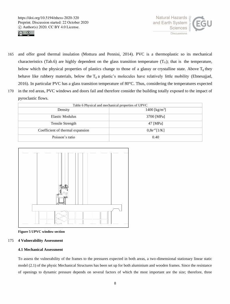
3.3 UPVC Windows
Another common material to produce windows and doors is UPVC. UPVC is a material composed of 160
macromolecules which are in turn formed by hydrogen, carbon and chlorine atoms. A UPVC window and door
frame has very similar characteristics to those of wood. UPVC has a low mechanical resistance; to overcome this,
multi-chamber profiles are extruded and reinforced with the help of metal elements (Fig.5). These windows and
doors have the main characteristic of resisting very well to the aggressions of atmospheric agents, are very light
https://doi.org/10.5194/nhess-2020-320Preprint. Discussion started: 22 October 2020c© Author(s) 2020. CC BY 4.0 License.
8
and offer good thermal insulation (Mottura and Pennisi, 2014). PVC is a thermoplastic so its mechanical 165
characteristics (Tab.6) are highly dependent on the glass transition temperature (TG); that is the temperature,
below which the physical properties of plastics change to those of a glassy or crystalline state. Above Tg they
behave like rubbery materials, below the Tg a plastic’s molecules have relatively little mobility (Ebnesajjad,
2016). In particular PVC has a glass transition temperature of 80°C. Thus, considering the temperatures expected
in the red areas, PVC windows and doors fail and therefore consider the building totally exposed to the impact of 170
pyroclastic flows.
Table 6 Physical and mechanical properties of UPVC Density 1400 [kg/m3]
Elastic Modulus 3700 [MPa]
Tensile Strength 47 [MPa]
Coefficient of thermal expansion 0,8e-4 [1/K]
Poisson’s ratio 0.40
Figure 5 UPVC window section
4 Vulnerability Assessment 175
4.1 Mechanical Assessment
To assess the vulnerability of the frames to the pressures expected in both areas, a two-dimensional stationary linear static
model (2.1) of the physic Mechanical Structures has been set up for both aluminium and wooden frames. Since the resistance
of openings to dynamic pressure depends on several factors of which the most important are the size; therefore, three
https://doi.org/10.5194/nhess-2020-320Preprint. Discussion started: 22 October 2020c© Author(s) 2020. CC BY 4.0 License.

9
different heights have been considered for each group of windows, i.e. for the large openings a height of 2.4 m had been 180
considered, for the Typical a height of 1.2 m and for the small a height of 0.8 m has been considered; and for each window
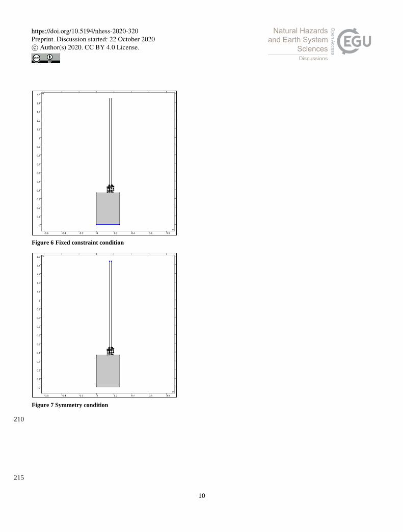
size the different thicknesses of the glass have been considered. Furthermore, it has been considered a fixed constraint (2.3)
at the base of the wall on which the window is placed (Fig.3). Additionally, it has been considered half section in order to
reduce the computational time, assuming a condition of symmetry (2.4) in the upper part of the window.
185
0 = ∇ ∙ (FS)T + FV (2.1)
𝐹𝑉 = I + ∇u (2.2)
𝑢 = 0 (2.3)
𝑢 ∙ 𝑛 = 0 (2.4)
190
In addition, a uniformly distributed load applied (2.5) on the external front has been assumed, in favor of opening, which is
linearly variable according to a parameter that has been imposed through a range function.
𝑆 ∙ n = 𝐹𝐴 (2.5)
𝐹𝐴 = 𝐹𝐿
𝑑 (2.6) 195
For modelling better, the problem and overcoming the convergence problem, it has been necessary to insert a Stop Function
in the Solver Configuration, imposing an if condition for the glass:
comp1.StressMax > 40[MPa]
200
Subsequently, from these first mechanical analyses, the glass of 4 mm of large dimensions, therefore with height equals to
2.4 m is the most vulnerable because the calculated breaking pressure is equal to 0.6 kPa (Tab.7). This situation is not
entirely similar for wooden frames, as the glass of this type is placed inside the frame without the aid of gaskets, so the glass
is perfectly embedded in the frame itself (Tab.8). Although the glass in the case of wooden frames may be suitable to
withstand the expected pressures, the problem lies in the resistance of the glass to temperature variation. 205
https://doi.org/10.5194/nhess-2020-320Preprint. Discussion started: 22 October 2020c© Author(s) 2020. CC BY 4.0 License.
10
Figure 6 Fixed constraint condition
Figure 7 Symmetry condition
210
215
https://doi.org/10.5194/nhess-2020-320Preprint. Discussion started: 22 October 2020c© Author(s) 2020. CC BY 4.0 License.

11
Table 7 Glass breakage load aluminium windows
Frame Glass
Aluminium
SODA LIME GLASS
Large Typical Small
4mm 5mm 6mm 4mm 5mm 6mm 4mm 5mm 6mm
0,6 kPa 1 kPa 1,3 kPa 2 kPa 3 kPa 4,3 kPa 5,3 kPa 8 kPa 10,3 kPa
Table 8 Glass breakage load timber windows
Frame Glass
Wood
SODA LIME GLASS
Large Typical Small
4mm 5mm 6mm 4mm 5mm 6mm 4mm 5mm 6mm
1.6 kPa 2.3 kPa 3 kPa 4.3 kPa 6.3 kPa 9.3 kPa 8.6 kPa 14.6 kPa 21.6 kPa
4.2 Thermal Assessment
Since the pyroclastic flows can be schematised both as pressures and as temperature variations, a thermal analysis also had to 220
be set. The models analysed are aluminium and thermal break aluminium. In order to tackle this problem, two different types
of thermal analysis have been accomplished. A 3D heat transfer to assess the thermal shock for the glass and a 2D thermal
stress for the entire windows.
4.2.1 Thermal Shock
Thermal shock occurs when a thermal gradient causes different parts of an object to expand in different quantities. This 225
differential expansion can also be understood in terms of stress or deformation (3.1). At some point, this stress may exceed
the strength of the material, causing a crack to form. If nothing prevents this crack from propagating through the material,
the glazing will lose its structural integrity. Glass objects are particularly vulnerable to failure due to thermal shock, due to
their low strength and low thermal conductivity. If the glass is then suddenly exposed to extreme heat, the shock will cause
the glass to break. 230
Δ𝑇 = (𝜎𝑇𝑆 ∗ (1− 𝜐))
𝐸 ∗ 𝛼 (3.1)
where:
• σTS is the yield strength of the material, 235
• ν Poisson’s ratio,
https://doi.org/10.5194/nhess-2020-320Preprint. Discussion started: 22 October 2020c© Author(s) 2020. CC BY 4.0 License.
12
• E Elastic modulus,
• α coefficient of thermal expansions.
In the case of soda lime glass, the critical temperature is 52 °C. Once the critical temperature is defined, it has been 240
necessary to assess the time to reach it through the heat transfer equation (3.2)
ρCp(δT
δt + 𝑢𝑡𝑟𝑎𝑛𝑠 ∙ ∇T) + ∇ ∙ q+ qr = - αT:
𝑑𝑆
𝑑𝑡 + 𝑄 (3.2)
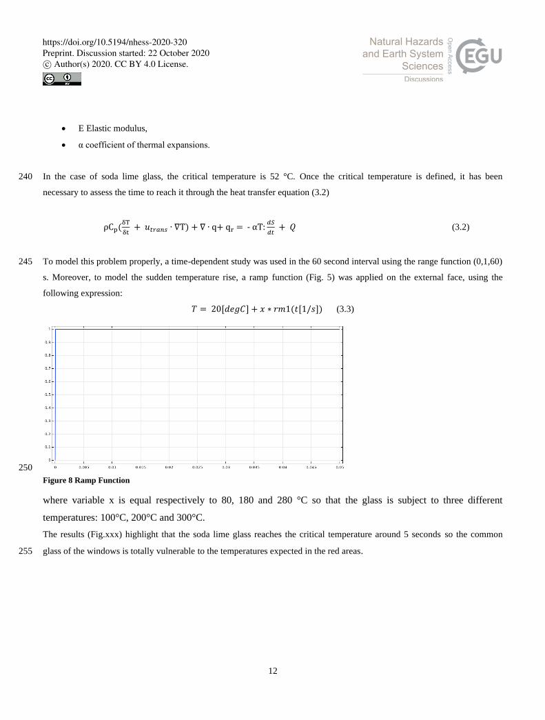
To model this problem properly, a time-dependent study was used in the 60 second interval using the range function (0,1,60) 245
s. Moreover, to model the sudden temperature rise, a ramp function (Fig. 5) was applied on the external face, using the
following expression:
𝑇 = 20[𝑑𝑒𝑔𝐶] + 𝑥 ∗ 𝑟𝑚1(𝑡[1/𝑠]) (3.3)
250
Figure 8 Ramp Function
where variable x is equal respectively to 80, 180 and 280 °C so that the glass is subject to three different
temperatures: 100°C, 200°C and 300°C.
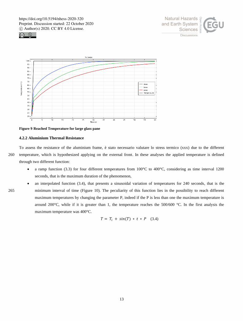
The results (Fig.xxx) highlight that the soda lime glass reaches the critical temperature around 5 seconds so the common
glass of the windows is totally vulnerable to the temperatures expected in the red areas. 255
https://doi.org/10.5194/nhess-2020-320Preprint. Discussion started: 22 October 2020c© Author(s) 2020. CC BY 4.0 License.
13
Figure 9 Reached Temperature for large glass pane
4.2.2 Aluminium Thermal Resistance
To assess the resistance of the aluminium frame, è stato necessario valutare lo stress termico (xxx) due to the different
temperature, which is hypothesized applying on the external front. In these analyses the applied temperature is defined 260
through two different function:
• a ramp function (3.3) for four different temperatures from 100°C to 400°C, considering as time interval 1200
seconds, that is the maximum duration of the phenomenon,
• an interpolated function (3.4), that presents a sinusoidal variation of temperatures for 240 seconds, that is the
minimum interval of time (Figure 10). The peculiarity of this function lies in the possibility to reach different 265
maximum temperatures by changing the parameter P, indeed if the P is less than one the maximum temperature is
around 200°C, while if it is greater than 1, the temperature reaches the 500/600 °C. In the first analysis the
maximum temperature was 400°C.
𝑇 = 𝑇𝑖 + 𝑠𝑖𝑛(𝑇) ∗ 𝑡 ∗ 𝑃 (3.4)
https://doi.org/10.5194/nhess-2020-320Preprint. Discussion started: 22 October 2020c© Author(s) 2020. CC BY 4.0 License.

14
270
Figure 10 Interpolation function
These first analyses show that the aluminium frame can resist the high temperatures, and the real issues are the plastic
material of thermal break and sealing. Indeed, from the first analysis, the polyamide reaches this temperature in a range of
600s in the case of 100°C, while in the case of 200°C, 300°C and 400°C the time is reduced to 50s, 20s and 14s respectively
(Fig.11). Besides the EPDM, considering the temperature higher than 100°C, it reaches its critical temperature around the 30 275
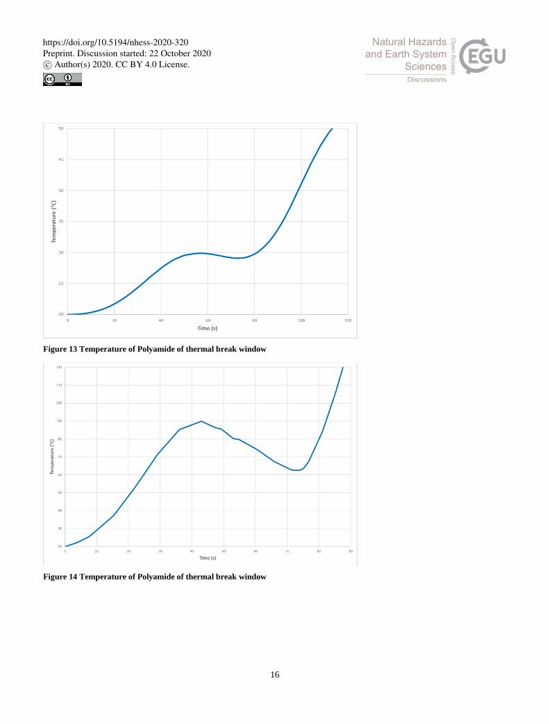
seconds and lower (Fig. 12). Finally, if the temperature is described by the interpolated function (3.4), the results show that
also in this case the plastic elements are the most vulnerable components of a window; indeed the polyamide reaches its Tg
about 100s (Figure 13). At the same time, the EPDM reaches its Tg around 95 s (Figure 14). Besides the aluminium window
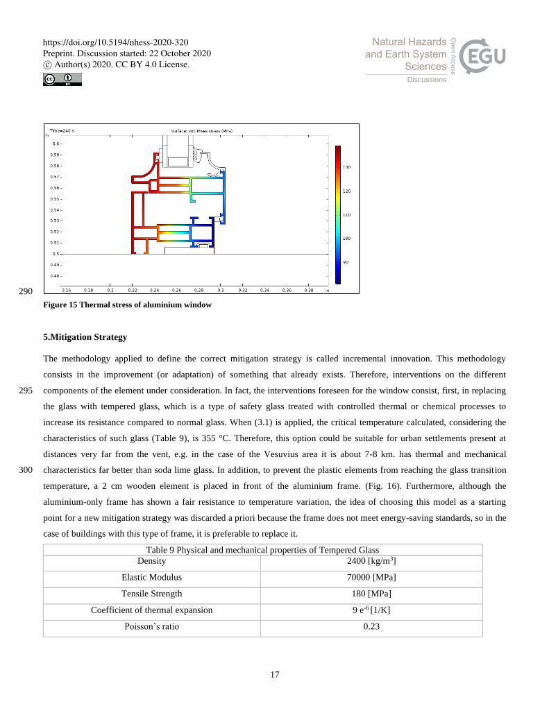
has been analysed through the function (3.4) showing a certain resistance to temperature variations, in fact, the frame does
not reach the breaking tension (Fig. 15), and the only vulnerable plastic element is the glass seal. 280
https://doi.org/10.5194/nhess-2020-320Preprint. Discussion started: 22 October 2020c© Author(s) 2020. CC BY 4.0 License.

15
Figure 11 Temperature of Polyamide of thermal break window
Figure 12 Temperature of EPDM of thermal break window
285
https://doi.org/10.5194/nhess-2020-320Preprint. Discussion started: 22 October 2020c© Author(s) 2020. CC BY 4.0 License.
16
Figure 13 Temperature of Polyamide of thermal break window
Figure 14 Temperature of Polyamide of thermal break window
https://doi.org/10.5194/nhess-2020-320Preprint. Discussion started: 22 October 2020c© Author(s) 2020. CC BY 4.0 License.
17
290
Figure 15 Thermal stress of aluminium window
5.Mitigation Strategy
The methodology applied to define the correct mitigation strategy is called incremental innovation. This methodology
consists in the improvement (or adaptation) of something that already exists. Therefore, interventions on the different
components of the element under consideration. In fact, the interventions foreseen for the window consist, first, in replacing 295
the glass with tempered glass, which is a type of safety glass treated with controlled thermal or chemical processes to
increase its resistance compared to normal glass. When (3.1) is applied, the critical temperature calculated, considering the
characteristics of such glass (Table 9), is 355 °C. Therefore, this option could be suitable for urban settlements present at
distances very far from the vent, e.g. in the case of the Vesuvius area it is about 7-8 km. has thermal and mechanical
characteristics far better than soda lime glass. In addition, to prevent the plastic elements from reaching the glass transition 300
temperature, a 2 cm wooden element is placed in front of the aluminium frame. (Fig. 16). Furthermore, although the
aluminium-only frame has shown a fair resistance to temperature variation, the idea of choosing this model as a starting
point for a new mitigation strategy was discarded a priori because the frame does not meet energy-saving standards, so in the
case of buildings with this type of frame, it is preferable to replace it.
Table 9 Physical and mechanical properties of Tempered Glass
Density 2400 [kg/m3]
Elastic Modulus 70000 [MPa]
Tensile Strength 180 [MPa]
Coefficient of thermal expansion 9 e-6 [1/K]
Poisson’s ratio 0.23
https://doi.org/10.5194/nhess-2020-320Preprint. Discussion started: 22 October 2020c© Author(s) 2020. CC BY 4.0 License.
18
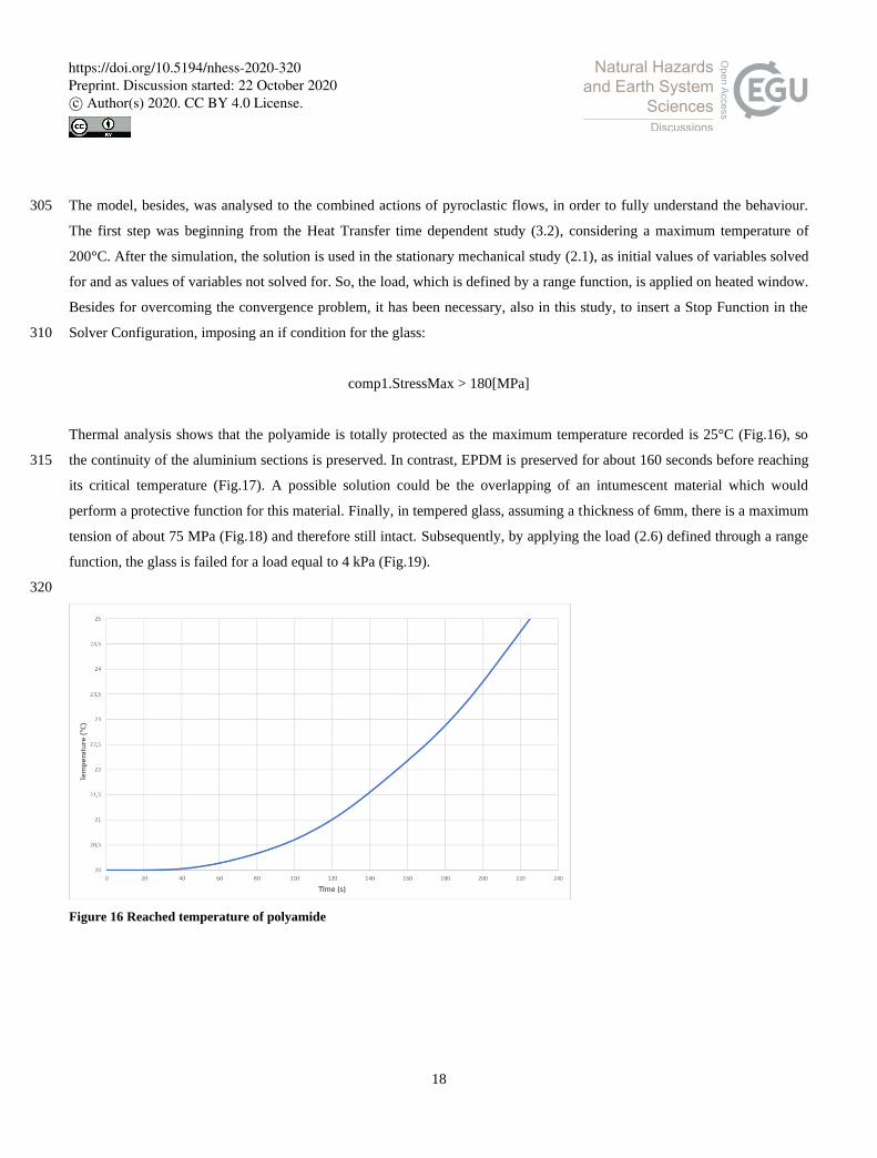
The model, besides, was analysed to the combined actions of pyroclastic flows, in order to fully understand the behaviour. 305
The first step was beginning from the Heat Transfer time dependent study (3.2), considering a maximum temperature of
200°C. After the simulation, the solution is used in the stationary mechanical study (2.1), as initial values of variables solved
for and as values of variables not solved for. So, the load, which is defined by a range function, is applied on heated window.
Besides for overcoming the convergence problem, it has been necessary, also in this study, to insert a Stop Function in the
Solver Configuration, imposing an if condition for the glass: 310
comp1.StressMax > 180[MPa]
Thermal analysis shows that the polyamide is totally protected as the maximum temperature recorded is 25°C (Fig.16), so
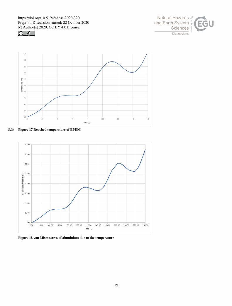
the continuity of the aluminium sections is preserved. In contrast, EPDM is preserved for about 160 seconds before reaching 315
its critical temperature (Fig.17). A possible solution could be the overlapping of an intumescent material which would
perform a protective function for this material. Finally, in tempered glass, assuming a thickness of 6mm, there is a maximum
tension of about 75 MPa (Fig.18) and therefore still intact. Subsequently, by applying the load (2.6) defined through a range
function, the glass is failed for a load equal to 4 kPa (Fig.19).
320
Figure 16 Reached temperature of polyamide
https://doi.org/10.5194/nhess-2020-320Preprint. Discussion started: 22 October 2020c© Author(s) 2020. CC BY 4.0 License.
19
Figure 17 Reached tempersture of EPDM 325
Figure 18 von Mises stress of aluminium due to the temperature
https://doi.org/10.5194/nhess-2020-320Preprint. Discussion started: 22 October 2020c© Author(s) 2020. CC BY 4.0 License.

20
330
Figure 19 Breaking load for tempered glass
6. Fluid dynamic Assessment
A fluid-dynamic and heat transfer evaluation have been made in the turbulent field, to study the shielding effect of the
shutter, changing the inclination of the slots and evaluating if the plastic elements reach the relative critical temperatures. 335
The model uses two different studies: one solving for the turbulent flow around the wall using a Turbulent Flow, k-ε physics
interface (4.1), and the other solving for the heat transfer using a Nonisothermal Heat Transfer physics interface (xxx).
ρ(𝐮𝐟𝐥𝐮𝐢𝐝 ∙ ∇)𝐮𝐟𝐥𝐮𝐢𝐝 = ∇ ∙ [−p𝐈 + K] + F (4.1)
340
p∇ ∙ 𝐮𝐟𝐥𝐮𝐢𝐝 = 0 (4.2)
𝐊 = (μ + μT) (∇ ufluid + (∇ufluid)T) (4.3)
−𝐧 ∙ 𝐪 = ρCpuτTw − T
T+ (4.4) 345
The fluid-flow geometry (Figure 20), is defined as a rectangle where the fluid enters to the right side with a speed of 25 m/s,
besides in the centre of the domain there is a piece of wall with two windows, covered by louvre shutters. Moreover two
https://doi.org/10.5194/nhess-2020-320Preprint. Discussion started: 22 October 2020c© Author(s) 2020. CC BY 4.0 License.

21
types of louvre have been considered, one with an angle of 45° and another one of 60°. Finally the exit is on the left side,
where the hypothesized pressure is equal to 0 Pa. The hypotheses are: 350
• Incompressible fluid,
• Turbulent movement,
• Homogeneous density and speed profile.
355
Figure 20 Geometric model for CFD
The physical characteristics of the fluid (Table 10) are:
Table 10 Physical and mechanical properties of Tempered Glass
Density 2265 [kg/m3]
Dynamic viscosity 0.001 [Pa * s]
Thermal conductivity 2.2 [W/m * K]
Heat capacity at constant pressure 1255 [J/kg * K]
Ratio of specific heats 1
Once the turbulent field had been studied, the solution obtained was used as initial values for the study of Heat Transfer in 360
Solids and Fluids, where the temperature is expressed through the function (3.7) through a time interval of 240 seconds.
The results highlight that shutters, commonly used, are not suitable for window protection against the flow. Indeed the
EPDM, in both cases considered, reaches the critical temperature after about 100 seconds. At the same time, polyamide
reaches its glass transition temperature after about 120 seconds (Fig. 21). Also, the glass is exposed to the effects of
pyroclastic flow, indeed it breaks due to thermal shock after 20 seconds (Fig. 22). 365
https://doi.org/10.5194/nhess-2020-320Preprint. Discussion started: 22 October 2020c© Author(s) 2020. CC BY 4.0 License.

22
Figure 21 Reached temperature by polyamide and EPDM
Figure 22 Reached temperature by polyamide and EPDM
https://doi.org/10.5194/nhess-2020-320Preprint. Discussion started: 22 October 2020c© Author(s) 2020. CC BY 4.0 License.
23
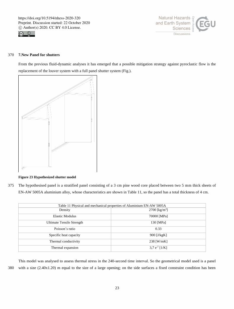
7.New Panel for shutters 370
From the previous fluid-dynamic analyses it has emerged that a possible mitigation strategy against pyroclastic flow is the
replacement of the louver system with a full panel shutter system (Fig.).
Figure 23 Hypothesized shutter model
The hypothesised panel is a stratified panel consisting of a 3 cm pine wood core placed between two 5 mm thick sheets of 375
EN-AW 5005A aluminium alloy, whose characteristics are shown in Table 11, so the panel has a total thickness of 4 cm.
Table 11 Physical and mechanical properties of Aluminium EN-AW 5005A Density 2700 [kg/m3]
Elastic Modulus 70000 [MPa]
Ultimate Tensile Strength 130 [MPa]
Poisson’s ratio 0.33
Specific heat capacity 900 [J/kgK]
Thermal conductivity 238 [W/mK]
Thermal expansion 3,7 e-7 [1/K]
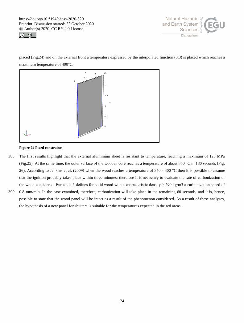
This model was analysed to assess thermal stress in the 240-second time interval. So the geometrical model used is a panel
with a size (2.40x1.20) m equal to the size of a large opening; on the side surfaces a fixed constraint condition has been 380
https://doi.org/10.5194/nhess-2020-320Preprint. Discussion started: 22 October 2020c© Author(s) 2020. CC BY 4.0 License.
24
placed (Fig.24) and on the external front a temperature expressed by the interpolated function (3.3) is placed which reaches a
maximum temperature of 400°C.
Figure 24 Fixed constraints
The first results highlight that the external aluminium sheet is resistant to temperature, reaching a maximum of 128 MPa 385
(Fig.25). At the same time, the outer surface of the wooden core reaches a temperature of about 350 °C in 180 seconds (Fig.
26). According to Jenkins et al. (2009) when the wood reaches a temperature of 350 - 400 °C then it is possible to assume
that the ignition probably takes place within three minutes; therefore it is necessary to evaluate the rate of carbonization of
the wood considered. Eurocode 5 defines for solid wood with a characteristic density ≥ 290 kg/m3 a carbonization speed of
0.8 mm/min. In the case examined, therefore, carbonization will take place in the remaining 60 seconds, and it is, hence, 390
possible to state that the wood panel will be intact as a result of the phenomenon considered. As a result of these analyses,
the hypothesis of a new panel for shutters is suitable for the temperatures expected in the red areas.
https://doi.org/10.5194/nhess-2020-320Preprint. Discussion started: 22 October 2020c© Author(s) 2020. CC BY 4.0 License.

25
Figure 25 von Mises stress of aluminium
395
Figure 26 Reached temperature of wood core
https://doi.org/10.5194/nhess-2020-320Preprint. Discussion started: 22 October 2020c© Author(s) 2020. CC BY 4.0 License.

26
Conclusion
Research into mitigation technologies to reduce the volcanic risk of buildings represents a fundamental field of investigation 400
for the definition of new resilient areas where rehabilitation plans will be faster and cheaper. Through this study, it has been
demonstrated that incremental strategies represent a suitable strategy for the protection of the most vulnerable elements of
the building. Moreover, these first analyses have shown that the pyroclastic flow represents a danger especially for the
temperatures that characterise them, in fact not only glass fails as a result of thermal stress but also the other constituent
elements such as gaskets and thermal break are vulnerable as thermoplastics. Furthermore, fluid-dynamic analyses have 405
shown that shutters, which had been hypothesised as a possible filter/protection element against flows, are unsuitable for this
purpose. Therefore, it is necessary to provide for replacement with a sandwich panel, which can withstand the expected
temperatures.
In the case of Vesuvius and Campi Flegrei, the principal impediment to the implementation of these proposals is the size of
the likely afflicted regions, which suggests relevant questions about the financial sustainability of mitigation measures. Local 410
governments and residents need to be fully conscious of the likely damage resulting from an eruption and the cost-
effectiveness of possible mitigation interventions. Regarding the economic, political and social "weight" of volcanic risk in
densely populated areas, a valid method of assessing the effectiveness of mitigation solutions can contribute objective
assistance to strategic choices and emergency plans. The approach discussed in this document, although regarding the area of
Vesuvius and Campi Flegrei in the specific parameters analysed (hazard characterisation, building typologies, construction 415
technologies), represents a methodology that could also be adopted in other contexts. Further work is underway to
understand the behaviour of shutters considering a fluid-dynamic problem and a 3D model of the window to analyse the
contribution of further elements such as the hinges and the actual closing system, in addition, models for combined pressure
and temperature analysis are being implemented.
References 420
Baxter, P. J., et al. (2008). “Emergency planning and mitigation at Vesuvius: A new evidence-based approach.” J. Volcanol. Geotherm.
Res., 178(3), 454–473.
Baxter, P. J., Boyd, R., Cole, P., Neri, A., Spence, R. J. S., and Zuccaro, G. (2005). “The impacts of pyroclastic surges on buildings at the
eruption of the Soufrière Hills volcano,Montserrat.” Bull. Volcanol., 67(4), 292–313.
Baxter, P. J., Woo, G., and Pomonis, A. (1998). “Preliminary assessment of volcanic risk on Montserrat.” Montserrat Volcano 425
Observatory, Montserrat, West Indies.
Carrot, C., Bendaoud, A., Pillon. C., (2015). Polyvinyl Butyral from: Handbook of Thermoplastics CRC Press
Convertito, V., and Zollo, A. (2011). “Assessment of pre-crisis and syncrisis seismic hazard at Campi Flegrei and Mt. Vesuvius volcanoes,
Campania, southern Italy.” Bull. Volcanol., 73(6), 767–783.
Ebnesajjad, S. (2016) “Expanded PTFE applications handbook: Technology, manufacturing and applications.” William Andrew 430
Publishing.
https://doi.org/10.5194/nhess-2020-320Preprint. Discussion started: 22 October 2020c© Author(s) 2020. CC BY 4.0 License.

27
Esposti Ongaro, T., Neri, A., Todesco, M., and Macedonio, G. (2001). “Pyroclastic flow hazard assessment at Vesuvius by using
numerical modelling. 2: Analysis of flow variables”. Bull. Volcanol., 64, 78-191.
Gurioli L., Sulpizio R., Cioni R., Sbrana A., Santacroce R., Luperini W., Andronico D., 2010, Pyroclastic flow hazard assessment at
Somma -Vesuvius based on the geological record. Bull Volcanol 72:1021-1038, Springer-Verlag. 435
International Volcanic Health Hazard Network (IVHHN), Cities and Volcanoes Commission (CaV), GNS Science, United States
Geological Survey (USGS). (2009). Guidelines on preparedness before, during
and after an ashfall, IVHHN, Durham, UK.
Jenkins S., Baxter P., Spence R., Purser D., Brown A., 2009, Potential for fire, building damage and casualties following PDC.
Vulnerabilita degli elementi esposti e mappe di scenario di danno conseguenti a fenomeni eruttivi del vesuvio e dei campi flegrei, 440
Deliverable 2.5
Mottura, G., and Pennisi, A. (2014). “Serramenti e schermature solari”, Maggioli Editore, ISBN: 978-8891600929
Neri, A., et al. (2008). “Developing an event tree for probabilistic hazard and risk assessment at Vesuvius.” J. Volcanol. Geotherm. Res.,
178(3), 397–415.
Neri, A., Esposti Ongaro, T., Macedonio, G., and Gidaspow, D. (2003). “Multiparticle simulation of collapsing volcanic columns and 445
pyroclastic flows.” J. Geophys. Res., 108(B4), 2202–2225.
Petrazzuoli, S. M., and Zuccaro, G. (2004). “Structural resistance of reinforced concrete buildings under pyroclastic flows: A study of the
Vesuvian area.” J. Volcanol. Geotherm. Res., 133(1-4), 353–364.
Spence R.J.S., Baxter P.J., Zuccaro G. (2004a). Building vulnerability and human casualty estimation for a pyroclastic flow: a model and
its application to Vesuvius. J. Volcanol. Geoth. Res. 133 (2004):321–343, 2004. 450
Spence R., Zuccaro G., Petrazzuoli S., Baxter P.J., (2004b). The resistance of buildings to pyroclastic flows: theoretical and experimental
studies in relation to Vesuvius. ASCE Nat Hazards Rev 5:48–50. ISSN: 1527-6988, 2004.
Todesco, M., and Longo, A. (2002). “Pyroclastic flow hazard assessment at Vesuvius by usinf numerical modelling. 1: Large scale
dynamics”. Bull. Volcanol., 64, 155-177.
Zuccaro G (2004). Final report SAVE. Project Link to the Web Page of the ‘‘Save’’ Project in ‘‘Atlantis’’. 455
http://gndt.ingv.it/Att_scient/Prodotti_attesi_2004/Dolce_Zuccaro/Mappe/ Start2.htm. Roma
Zuccaro G., Albanese V., Cacace F., Mercuri C. and Papa F., (2008a). Seismic Vulnerability Evaluations within the Structural and
Functional Survey Activities of the COM bases in Italy, AIP Conference, 2008.
Zuccaro G., Cacace F., Spence R.J.S., Baxter P.J., (2008b). Impact of explosive eruption scenarios at Vesuvius", J Volcanol Geoth Res
178(2008):416–453, 2008. 460
Zuccaro G. and Cacace F. (2010). Seismic impact scenarios in the volcanic areas in Campania. In: F.M. Mazzolani. Urban habitat
construction under catastrophic events. p. 725-730, CRC Press, ISBN: 9780415606851.
Zuccaro G., De Gregorio D. (2011). Valutazioni di impatto in aree vulcaniche - Vesuvio e Campi Flegrei ", In: Lirer L., Il vulcanismo
esplosivo, p. 56-73, CNR press, ISBN: 979-12-200-1041-2
Zuccaro G., Cacace F., De Gregorio D. (2012). Buildings inventory for seismic vulnerability assessment at National and regional scale", 465
In: 15th World Conference on Earthquake Engineering, 15th WCEE 2012, Lisbon (Portugal), 24–28 September 2012. Paper no 2829,
2012.
Zuccaro G. and De Gregorio D., (2013). Time and Space dependency in impact damage evaluation of a sub-Plinian eruption at Mount
Vesuvius. Natural Hazard (2013) 68:1399–1423. DOI: 10.1007/s11069-013-0571-8, 2013.
https://doi.org/10.5194/nhess-2020-320Preprint. Discussion started: 22 October 2020c© Author(s) 2020. CC BY 4.0 License.

28
Zuccaro G., Leone M. F., Del Cogliano D., Sgroi A. (2013). Economic impact of explosive volcanic eruptions: A simulation-based 470
assessment model applied to Campania region volcanoes. JOURNAL OF VOLCANOLOGY AND GEOTHERMAL RESEARCH,
vol. 266, p. 1-15, ISSN: 0377-0273, doi: 10.1016/j.jvolgeores.2013.09.002.
Zuccaro G., De Gregorio D., Baxter P. (2014). Human and Structural Vulnerability to Volcanic Processes. In: P. Papale. (a cura di): J.
Shroder, Volcanic Hazards, Risks and Disasters. vol. Chapter 10, p. 261-288, Elsevier, ISBN: 9780123964533.
475
https://doi.org/10.5194/nhess-2020-320Preprint. Discussion started: 22 October 2020c© Author(s) 2020. CC BY 4.0 License.
Recommended