Pulse Code ModulationPulse Code Modulation
Pulse Code Modulation (PCM) Pulse Code Modulation (PCM)
Analog voice data must be translated into a series of Analog voice data must be translated into a series of binary digits before they can be transmitted.binary digits before they can be transmitted.
With With Pulse Code Modulation (PCM)Pulse Code Modulation (PCM), the amplitude of , the amplitude of the sound wave is sampled at regular intervals and the sound wave is sampled at regular intervals and translated into a binary number.translated into a binary number.
The difference between the original analog signal and The difference between the original analog signal and the translated digital signal is called the translated digital signal is called quantizing errorquantizing error..
PCM PCM
PCM uses a sampling rate of 8000 samples per PCM uses a sampling rate of 8000 samples per second.second.
Each sample is an 8 bit sample resulting in a Each sample is an 8 bit sample resulting in a digital rate of 64,000 bps (8 x 8000).digital rate of 64,000 bps (8 x 8000).
Converting Samples to BitsConverting Samples to Bits
QuantizingQuantizing Similar concept to pixelizationSimilar concept to pixelization Breaks wave into pieces, assigns a value in a Breaks wave into pieces, assigns a value in a
particular rangeparticular range 8-bit range allows for 256 possible sample 8-bit range allows for 256 possible sample
levelslevels More bits means greater detail, fewer bits More bits means greater detail, fewer bits
means less detailmeans less detail
MULTIPLEXING TYPESMULTIPLEXING TYPES
Frequency Division MultiplexingFrequency Division Multiplexing
Time Division MultiplexingTime Division Multiplexing
Wavelength Division MultiplexingWavelength Division Multiplexing
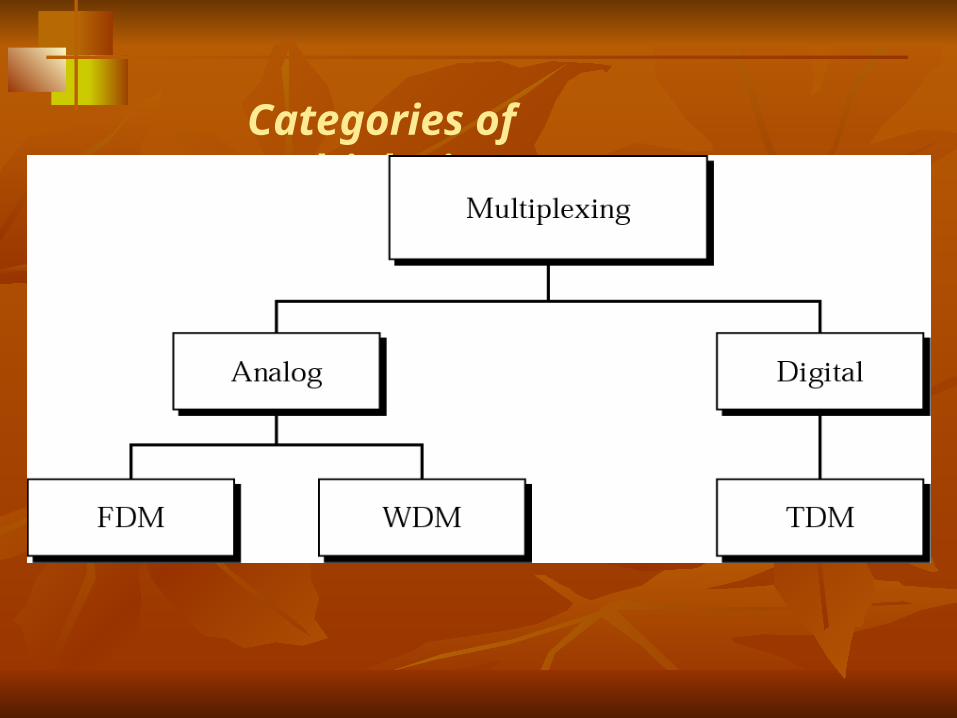
Categories of multiplexing
FDM
Is the process of translating individual speech circuits (300-3400Hz) into pre assigned slots within the bandwith of transmission medium. and, the preassigned slots are always available to each user
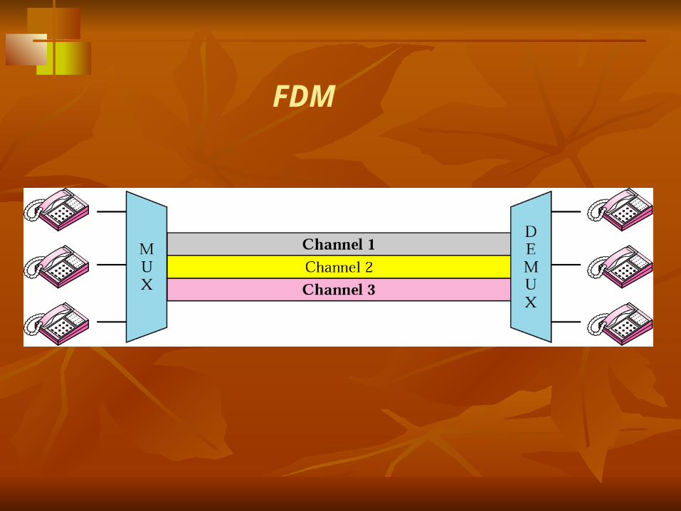
FDM
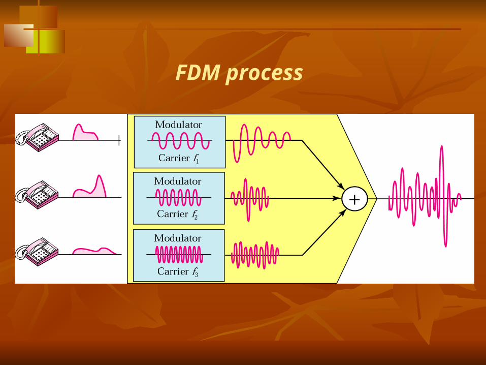
FDM process
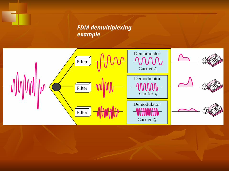
FDM demultiplexing example
TDMTDM
The process where a transmission medium is shared by a number of circuits in time domain by establishing a sequence of time slots during which individual channels can be transmitted…Thus the entire bandwidth is periodically available to each channel
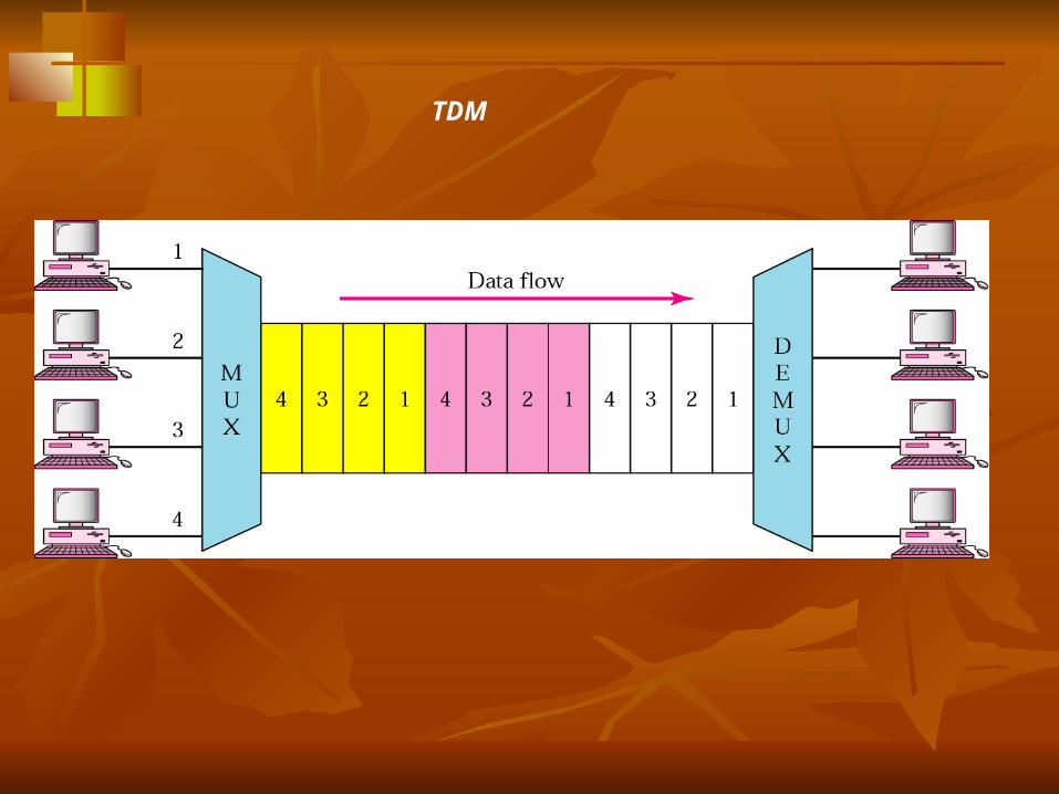
TDM
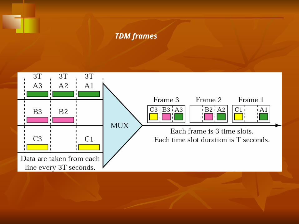
TDM frames
PCM PROCESSESPCM PROCESSES
FilteringFiltering SamplingSampling QuantizationQuantization EncodingEncoding Line codingLine coding
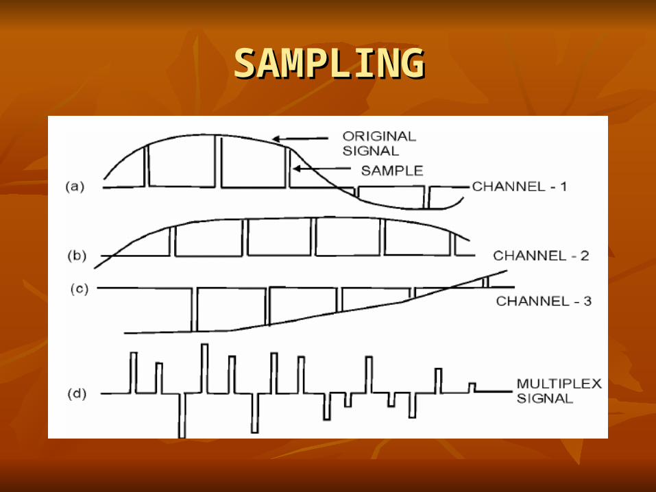
SAMPLINGSAMPLING
SAMPLING THEOREMSAMPLING THEOREM
“ “ If a band limited signal is sampled at regular If a band limited signal is sampled at regular intervals of time and at a rate equal to or more intervals of time and at a rate equal to or more than twice the highest signal frequency in the than twice the highest signal frequency in the band, then the sample contains all the band, then the sample contains all the information of the original signal”information of the original signal”
Fs= >2fHFs= >2fH
PULSE CODE MODULATIONPULSE CODE MODULATION
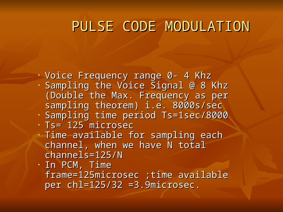
• Voice Frequency range 0- 4 KhzVoice Frequency range 0- 4 Khz• Sampling the Voice Signal @ 8 Khz Sampling the Voice Signal @ 8 Khz
(Double the Max. Frequency as per (Double the Max. Frequency as per sampling theorem) i.e. 8000s/secsampling theorem) i.e. 8000s/sec
• Sampling time period Ts=1sec/8000Sampling time period Ts=1sec/8000• Ts= 125 microsecTs= 125 microsec• Time available for sampling each channel, Time available for sampling each channel,
when we have N total channels=125/Nwhen we have N total channels=125/N• In PCM, Time frame=125microsec ;time In PCM, Time frame=125microsec ;time
available per chl=125/32 =3.9microsec. available per chl=125/32 =3.9microsec.
QUANTIZINGQUANTIZING
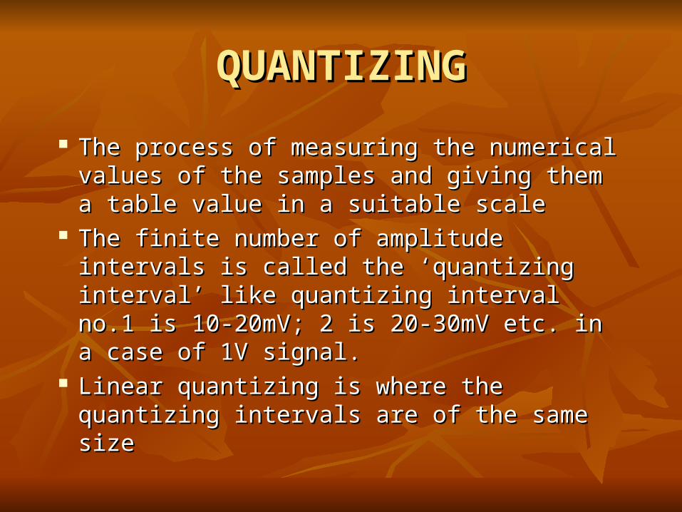
The process of measuring the numerical The process of measuring the numerical values of the samples and giving them a values of the samples and giving them a table value in a suitable scaletable value in a suitable scale
The finite number of amplitude intervals is The finite number of amplitude intervals is called the ‘quantizing interval’ like called the ‘quantizing interval’ like quantizing interval no.1 is 10-20mV; 2 is quantizing interval no.1 is 10-20mV; 2 is 20-30mV etc. in a case of 1V signal.20-30mV etc. in a case of 1V signal.
Linear quantizing is where the quantizing Linear quantizing is where the quantizing intervals are of the same sizeintervals are of the same size
QUANTIZINGQUANTIZING
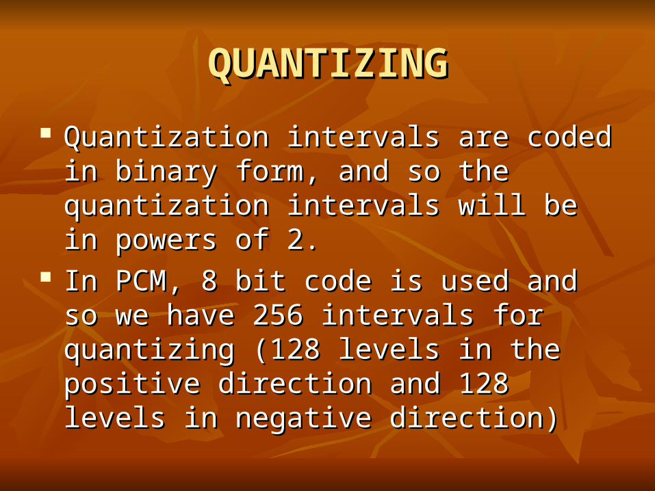
Quantization intervals are coded in binary Quantization intervals are coded in binary form, and so the quantization intervals will be form, and so the quantization intervals will be in powers of 2. in powers of 2.
In PCM, 8 bit code is used and so we have 256 In PCM, 8 bit code is used and so we have 256 intervals for quantizing (128 levels in the intervals for quantizing (128 levels in the positive direction and 128 levels in negative positive direction and 128 levels in negative direction)direction)
QUANTIZATION DISTORTIONQUANTIZATION DISTORTION
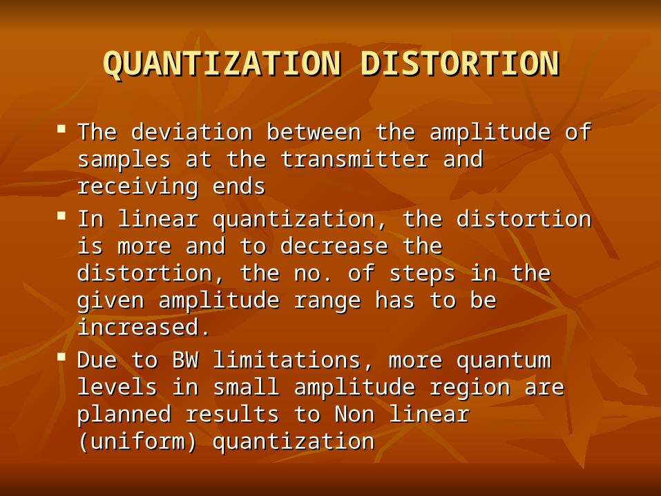
The deviation between the amplitude of The deviation between the amplitude of samples at the transmitter and receiving endssamples at the transmitter and receiving ends
In linear quantization, the distortion is more In linear quantization, the distortion is more and to decrease the distortion, the no. of steps and to decrease the distortion, the no. of steps in the given amplitude range has to be in the given amplitude range has to be increased.increased.
Due to BW limitations, more quantum levels in Due to BW limitations, more quantum levels in small amplitude region are planned results to small amplitude region are planned results to Non linear (uniform) quantization Non linear (uniform) quantization
COMPANDINGCOMPANDING
Is the process where non uniform quantization Is the process where non uniform quantization is achieved using segmented quantizationis achieved using segmented quantization
In companding, to specify the location of In companding, to specify the location of sample value, the following are necessary…sample value, the following are necessary…sign of the sample, the segment no., the sign of the sample, the segment no., the quantum level within the segment.quantum level within the segment.
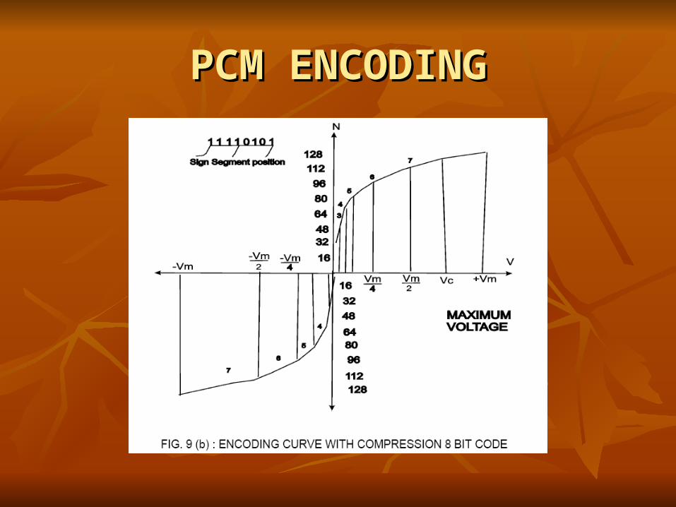
PCM ENCODINGPCM ENCODING
FRAME STRUCTUREFRAME STRUCTURE
In PCM we have 32 Ts and Ts 0 (FAW) In PCM we have 32 Ts and Ts 0 (FAW) carries the synchronization signals and FAW carries the synchronization signals and FAW digit value is X 0 0 1 1 0 1 1 . FAW digit value is X 0 0 1 1 0 1 1 . FAW transmitted in alternate frame. In FAW unused transmitted in alternate frame. In FAW unused frames, supervisory and alarm signals are frames, supervisory and alarm signals are transmittedtransmitted
Ts 16 carries the signalling information (for 2 Ts 16 carries the signalling information (for 2 channels)channels)
FRAME STRUCTUREFRAME STRUCTURE
For carrying the signalling for all 30 chls and For carrying the signalling for all 30 chls and for carrying sync. Data for all frames, in PCM for carrying sync. Data for all frames, in PCM 16 frame pattern is used and it is known as 16 frame pattern is used and it is known as multi framemulti frame
Duration of multi frame is 2msecs.Duration of multi frame is 2msecs.
PCM StandardsPCM Standards THERE ARE TWO STANDARDS OF PCM THERE ARE TWO STANDARDS OF PCM
NAMELY NAMELY 1) THE EUROPEAN 2 ) THE AMERICAN.1) THE EUROPEAN 2 ) THE AMERICAN. THEY DIFFER SLIGHTLY IN THE DETAIL OF THEY DIFFER SLIGHTLY IN THE DETAIL OF
THEIR WORKING BUT THE PRINCIPLES ARE THEIR WORKING BUT THE PRINCIPLES ARE THE SAME.THE SAME.
EUROPEAN PCM = 30 CHANNELSEUROPEAN PCM = 30 CHANNELS NORTH AMERICAN PCM = 24 CHANNELSNORTH AMERICAN PCM = 24 CHANNELS JAPANESE PCM = 24 CHANNELSJAPANESE PCM = 24 CHANNELS IN INDIA WE FOLLOW THE EUROPEAN PCM IN INDIA WE FOLLOW THE EUROPEAN PCM
OF 30 CHANNELS SYSTEM WORKING.OF 30 CHANNELS SYSTEM WORKING.
JUSTIFICATION TYPESJUSTIFICATION TYPES
Positive justification: Common Positive justification: Common synchronization bit rate offered at each synchronization bit rate offered at each tributary is higher than the bit rate of tributary is higher than the bit rate of individual tributary.individual tributary.
Positive-negative justificationPositive-negative justification Negative justificationNegative justification
Recommended