1
Pulsar HART DTM Instruction Manual

HART DTM INSTRUCTION MANUAL
2
PULSAR MEASUREMENT
3
Pulsar DTM Instruction Manual (SECOND EDITION REV 1)
February 2021
Part Number M-150-0-002-1P
COPYRIGHT
© Pulsar Measurement, 2020 - 21. All rights reserved. No part of this publication may be
reproduced, transmitted, transcribed, stored in a retrieval system, or translated into any
language in any form without the written permission of Pulsar Process Measurement Limited.
WARRANTY AND LIABILITY
Pulsar Process Measurement Limited guarantee for a period of 2 years from the date of delivery
that it will either exchange or repair any part of this product returned to Pulsar Process
Measurement Limited if it is found to be defective in material or workmanship, subject to the
defect not being due to unfair wear and tear, misuse, modification or alteration, accident,
misapplication, or negligence.
DISCLAIMER
Pulsar Measurement neither gives nor implies any process guarantee for this product and shall
have no liability in respect of any loss, injury or damage whatsoever arising out of the
application or use of any product or circuit described herein.
Every effort has been made to ensure accuracy of this documentation, but Pulsar Measurement
cannot be held liable for any errors.
Pulsar Measurement operates a policy of constant development and improvement and reserves
the right to amend technical details, as necessary.
CONTACT
For technical support, please contact:
Europe: [email protected]
Outside Europe: [email protected]
If you have any comments or suggestions about this product, please contact:
Europe: [email protected]
Outside Europe: [email protected]
Pulsar Measurement website: www.pulsarmeasurement.com
United States
11451 Belcher Road South
Largo,
FL 33773
888-473-9546
Canada
16456 Sixsmith Drive
Long Sault, Ont.
K0C 1P0
855-300-9151
United Kingdom
Cardinal Building, Enigma
Commercial Centre
Sandy’s Road, Malvern
WR14 1JJ
00 44 (0)1684 891371

HART DTM INSTRUCTION MANUAL
4
CONTENTS
Chapter 1: Start Here… ........................................................................................................... 6
About this Manual ............................................................................................................... 6
About the Pulsar DTM Software ..................................................................................... 7
Chapter 2 Installing The Pulsar DTM ................................................................................ 8
Installing the Pulsar DTM .................................................................................................. 8
Chapter 3 Connecting To the Pulsar DTM ................................................................... 11
Adding the DTM ................................................................................................................ 11
Selecting the correct Comport .................................................................................... 12
Selecting and connecting to a Pulsar device ......................................................... 12
User Interface layout ........................................................................................................ 14
Chapter 4 Online Parameterisation ................................................................................ 15
Symbol Key .......................................................................................................................... 15
Parameters ........................................................................................................................... 15
System Units ....................................................................................................................... 16
Application ........................................................................................................................... 17
Operation ............................................................................................................................. 17
Distance ................................................................................................................................ 18
Data Log parameters ....................................................................................................... 19
Temperature Logs ............................................................................................................. 19
System Logs ........................................................................................................................ 20
mA Output ........................................................................................................................... 21
Failed Mode ......................................................................................................................... 21
Compensation .................................................................................................................... 22
Stability .................................................................................................................................. 23
Damping ............................................................................................................................... 23
Filter ........................................................................................................................................ 24
System ................................................................................................................................... 24
System Info .......................................................................................................................... 25
Date & Time ........................................................................................................................ 25
Volume .................................................................................................................................. 26

PULSAR MEASUREMENT
5
Volume Setup ..................................................................................................................... 26
Volume Variables .............................................................................................................. 30
Level / Volume Breakpoints .......................................................................................... 31
Breakpoints Points Graph .............................................................................................. 32
HART commands ............................................................................................................... 33
Device Variables ................................................................................................................ 33
Device Information ........................................................................................................... 34
Review .................................................................................................................................... 34
Signal Condition ................................................................................................................ 35
4-20mA calibration ........................................................................................................... 35
Real time Clock .................................................................................................................. 36
Echo ........................................................................................................................................ 37
Echo Variables .................................................................................................................... 37
Loss limits ............................................................................................................................. 38
Echo Traces .......................................................................................................................... 39
Service ................................................................................................................................... 40
Level Trending .................................................................................................................... 41
Single parameter programming .................................................................................. 42
Chapter 5 Troubleshooting ................................................................................................ 43
Chapter 6 Disposal ................................................................................................................ 44

HART DTM INSTRUCTION MANUAL
6
CHAPTER 1: START HERE…
Congratulations on your purchase of Pulsar’s DTM software. This quality
system has been developed over many years and represents the latest in
high technology ultrasonic level measurement and control.
It has been designed to give you years of trouble-free performance, and a
few minutes spent reading this operating manual will ensure that your
installation is as simple as possible.
About this Manual
It is important that this manual is referred to for correct installation and
operation. There are various parts of the manual that offer additional help
or information as shown.
Tips
TIP: Look for this icon throughout your Pulsar Measurement manual to
f ind helpful information and answers to frequently asked questions .
Additional Information
Additional Information
At various parts of the manual, you will find sections
like this that explain specific things in more detail.

PULSAR MEASUREMENT
7
About the Pulsar DTM Software
The Pulsar DTM Software is a powerful tool that can be used in conjunction
with Pulsar’s HART devices. Once installation is complete of the Pulsar DTM
you will have the capability to communicate with a Pulsar device with FDT
frame applications, such as PACT ware.
Using the Pulsar DTM you will be able to the following:
• Parameterization of the Pulsar device.
• Diagnostic echo trace.
• Measured-value information display.
• Trend graph function.
• Calibration of device.
• Printing of parameter values.
The Pulsar HART Device Type Manager (DTM) is used to parameterize Pulsar
devices with HART capability. The universal and common practice
commands of the HART protocol 7 are supported, which are processed by
most HART devices.
System Requirements
Operating System: Windows 7 (latest service pack installed), 8 & 10.
Disk Space required: 15MB approx.
Permissions: Administrator privileges required for installation.
Important Information
For optimum results using the Pulsar DTM with our products, please contact
Pulsar for identification of the range of products available to be used in
conjunction with the Pulsar DTM.

HART DTM INSTRUCTION MANUAL
8
CHAPTER 2 INSTALLING THE PULSAR DTM
Installing the Pulsar DTM
Installation of the DTM software is simple, it can be downloaded from our
website:
www.pulsar-pm.com/Instrumentation/Support/Downloads/Software
After downloading the software on to a PC select the Windows Installer
package icon .
Upon selecting this you will then be taken through the process of installing
the DTM on to a local PC by a series of information windows.
If you have a previous version of the Pulsar DTM that is older than the version
being downloaded, you will need to first uninstall this older version.

PULSAR MEASUREMENT
9
You will now be prompted with a series of installation windows. Please
follow the prompt windows below to install the DTM successfully.
1. First screen of the
installation. When ready
to begin installation
please select ‘Next’.
2. This next window asks
you to select the
destination folder of
where the DTM files will
be stored on the local PC.

HART DTM INSTRUCTION MANUAL
10
3. Selecting ‘Install’ will
begin the DTM download,
and a progress bar will
appear.
4. A status bar will now
fill across the window
indicating the progress of
the installation.
5. After a few moments
the DTM will be
successfully installed on
to the local machine.
Clicking Finish will
complete the DTM
installation and allow it to
be utilised with
configuration software.

PULSAR MEASUREMENT
11
CHAPTER 3 CONNECTING TO THE PULSAR DTM
Pulsars DTM can now be used with proprietary software such as PACTware.
This section gives an example of how to install and use the Pulsar DTM using
PACTware software.
Adding the DTM
After opening the PACTware software the default home screen is displayed.
To add the Pulsar DTM to the software you must first update the device
catalogue so that the software can allow it to be used.
Select the option ‘View’ on the top tool bar and when the drop-down menu
opens, select Device Catalog, as shown below:
This will then open up a screen displaying all listed devices, to add the Pulsar
DTM select ‘Update Device Catalog’ and select yes to the question asked in
the pop-up window. When completed, open the Device Catalog once again
and the Pulsar DTM has been added to the list of available devices.
Return to the top menu bar and select the option ‘Device’, and from the
drop-down menu select ‘Add device’. You will now have a window appear
to allow you to select the pulsar DTM.

HART DTM INSTRUCTION MANUAL
12
Highlight the Pulsar DTM option and click OK, the project window should
now look like this:
Selecting the correct Comport
Prior to connecting to the Pulsar device, you will need to identify the
comport that a HART modem is assigned to.
The comport can be changed within the HART communication DTM
parameter settings.
Once the comport has been selected, you now need to add the Pulsar device
you are intending to connect to. For this example, a dBi HART sensor is
used.
Selecting and connecting to a Pulsar device
To select the Pulsar device, highlight the Comport number so it is solid blue
(as shown below):
From the top menu bar select ‘Device’ and from the options now available,
select ‘Add device’. You will now be presented with a popup window, select
the Pulsar device, and click OK. An example of the information in the
window is shown below:
The Pulsar device has been added in the project window underneath the
Comport number, indicating that it has been added successfully to the
project.

PULSAR MEASUREMENT
13
Connecting to the Pulsar device is simple, you will notice that the two icons
highlighted are apart meaning that there is currently no connection to the
device or to the comport.
Ensuring that the Pulsar device is highlighted, from the top menu select
‘Device’ and choose ‘Connect’. The icons will now change to indicate a
connection to the Comport and Pulsar device and will now look like the
below picture:
Double click on the Pulsar device to open the parameterisation window.
This will display the user interface navigation window that will allow you to
view and change parameters/Hart commands and look at echo traces from
the Pulsar device. The below screen is now displayed:

HART DTM INSTRUCTION MANUAL
14
User Interface layout
1. Shows the current Pulsar field device connected.
2. Navigation window to switch between each section of the device to
view/change information.
3. Connection options. Select ‘Reconnect’ if a drop in communication
happens. Or ‘Refresh’ to refresh the options available and information
held on the device.
4. Status bar indicating uploading/downloading of information and if a
device is successfully connected/disconnected. No further changes can
be made whilst this is in progress.
5. These buttons allow certain actions to take place:
• Selecting ‘OK’ will apply changes made and reload the application
window and a new parameterisation window will need to be opened.
• Selecting ‘Cancel’ will cancel any request made by the user.
• Selecting ‘Apply’ will action any change requested by the user and
keep the application window open.
6. Application area which displays the parameter and echo trace
information.
1
2
3 4 5
6

PULSAR MEASUREMENT
15
CHAPTER 4 ONLINE PARAMETERISATION
The online parameterisation navigation window for the device is split into
five main categories: Parameters, Volume, HART commands, Echo and
Service. Each of these categories have subsections where relevant
parameters can be changed to suite the application. Using the navigation
window to view and change parameters you will come across symbols
identifying certain actions, these are explained in the below table:
Symbol Key
SYMBOL DESCRIPTION
This is displayed when a parameter value box is being changed.
Parameter box is yellow, indicating that the value is changed
from its previous value. If satisfied with the change(s) made to
that page press Apply. The parameter box will then turn white
to indicate a successful change.
The software is currently downloading the parameter value.
Up or download
running. No
change is
possible
The software is currently performing a task, meaning the ability
to change another parameter or navigate to another section is
temporarily unavailable until the task has ended.
Communication running. Live information updated approx.
every 6 seconds.
At least one parameter is being changed.
Parameters
This section allows you to view and change the most common parameters
required to setup the device ready for use with the application. Within this
section there are seven subsections to help program the Pulsar device:
System units, Application, Data Logs, mA output, Compensation,
Stability and System.

HART DTM INSTRUCTION MANUAL
16
System Units
Selecting this section will display parameters that allow you to change the
measurement and volume units used and displayed for level and volume.
The options are shown below:
P104 Measurement Units
This parameter sets the units you want to use for programming and display.
OPTION DESCRIPTION
m (Default) All units of measurement are Metres
cm All units of measurement are Centimetres
mm All units of measurement are Millimetres
ft. All units of measurement are Feet
in All units of measurement are Inches
P605 Volume Unit
This parameter determines the units that are to be used and displayed, for
volume conversion. It is used in conjunction with P607 (maximum volume).
The choice of volume units is shown in the table below:
OPTION DESCRIPTION
None No Volume will be calculated or displayed
Tons Volume calculated and displayed in Tons
Tonnes Volume calculated and displayed in Tonnes
m3 Volume calculated and displayed in Cubic metres (default)
Litres Volume calculated and displayed in Litres
UKgal Volume calculated and displayed in UK Gallons
USGal Volume calculated and displayed in US Gallons
Cubic feet Volume calculated and displayed in Cubic feet

PULSAR MEASUREMENT
17
Application
This section has parameters to set the mode of operation and define the
range of the application.
Operation
P100 System Mode
This parameter sets the mode of operation when the device is running and
obtaining measurements.
OPTION DESCRIPTION
Distance Displays the distance from the transducer to the surface
measured.
Level Display shows how full the vessel is (Default).
Space Display shows how empty a vessel is.
Volume Display shows the volume of the vessel.
HART DTM INSTRUCTION MANUAL
18
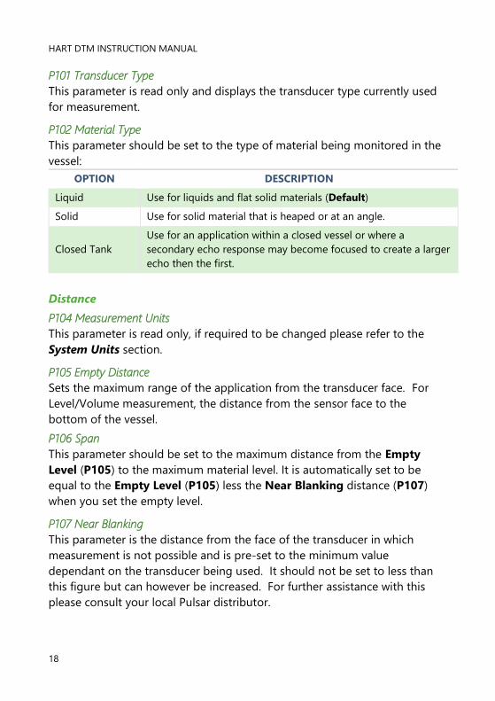
P101 Transducer Type
This parameter is read only and displays the transducer type currently used
for measurement.
P102 Material Type
This parameter should be set to the type of material being monitored in the
vessel:
OPTION DESCRIPTION
Liquid Use for liquids and flat solid materials (Default)
Solid Use for solid material that is heaped or at an angle.
Closed Tank
Use for an application within a closed vessel or where a
secondary echo response may become focused to create a larger
echo then the first.
Distance
P104 Measurement Units
This parameter is read only, if required to be changed please refer to the
System Units section.
P105 Empty Distance
Sets the maximum range of the application from the transducer face. For
Level/Volume measurement, the distance from the sensor face to the
bottom of the vessel.
P106 Span
This parameter should be set to the maximum distance from the Empty
Level (P105) to the maximum material level. It is automatically set to be
equal to the Empty Level (P105) less the Near Blanking distance (P107)
when you set the empty level.
P107 Near Blanking
This parameter is the distance from the face of the transducer in which
measurement is not possible and is pre-set to the minimum value
dependant on the transducer being used. It should not be set to less than
this figure but can however be increased. For further assistance with this
please consult your local Pulsar distributor.

PULSAR MEASUREMENT
19
P108 Far Blanking Distance
This is the distance (as a percentage of the empty level P105) beyond the
empty point that the unit will be able to measure, and by default is pre-set
to 20% of the empty level.
If the surface being monitored can be extended beyond the empty level
(P105) then the far blanking distance can be increased to a max. of 100% of
the empty level, provided it does not exceed the max range of the
transducer being used. This parameter is always entered as a % of the
empty level.
Data Log parameters
This section contains the temperature and system logs of the Pulsar device.
Temperature Logs
These parameters are read only and show temperature conditions seen by
the Temperature source (P852) in ºC. If P852 is changed they will be reset.
P580 Minimum Temperature
This parameter displays the minimum temperature recorded.
P581 Minimum Temperature Date
This parameter displays the date when the minimum temperature was
recorded.
HART DTM INSTRUCTION MANUAL
20
P582 Minimum Temperature Time
This parameter displays the time when the minimum temperature was
recorded.
P583 Maximum Temperature
This parameter displays the maximum temperature recorded.
P584 Maximum Temperature Date
This parameter displays the date when the maximum temperature was
recorded.
P585 Maximum Temperature Time
This parameter displays the time when the maximum temperature was
recorded.
P586 Temperature
This parameter displays the current temperature.
System Logs
The below parameters are read only and display information on when the
device was last powered and how long it was running for.
P940 No. of Starts
This displays the number of times the device has been powered up since
leaving the factory.
P941 Last Power Down Date
This displays the last date on which the power was removed from the device.
P942 Last Power Down Time
This displays the last time on which the power was removed from the device.
P943 Last Run Time (Minutes)
This displays how long the device was running for, in minutes, prior to its last
power down.
P944 Total Run Time (Hours)
This displays the accumulated number of hours that the device has been in
operation (powered up) since leaving the factory.

PULSAR MEASUREMENT
21
mA Output
This section allows adjustment of the mA span and the fail mode parameters
for the Pulsar device.
P834 mA Low Level
This parameter sets the level (in Measurement Units P104), at which 4mA
will occur, depending on the selected Mode of Operation (P100).
P835 mA High Level
This parameter sets level (in Measurement Units P104), at which 20mA will
occur, depending on the selected Mode of Operation (P100).
Failed Mode
P808 Failsafe Mode
This parameter sets the action of the mA output during a failsafe condition:
OPTION DESCRIPTION
Known Remain at the last Known value (Default)
High Will fail to the High value (100% Span / 20mA)
Low Will fail to the Low value (Empty / 4mA)
Very High Will fail to an output value of 22ma
Very Low Will fail to an output of 3.75mA
P809 Failsafe Time
In the event of a loss of echo condition the failsafe timer determines the
time before a failsafe mode is activated. Default = 2 minutes.

HART DTM INSTRUCTION MANUAL
22
If the timer expires, the device will go into failsafe, as determined by P808.
However, when a valid measurement is obtained then the displayed reading
and mA output will be restored, and the failsafe timer is reset.
Compensation
Displays parameters that can be changed to compensate for variations in
temperature, sound velocity and vapour, as well as applying offsets to the
measurement.
P851 Measurement Offset
The value of this parameter is added to the measured distance, in
Measurement Units (P104). This Offset will be added to the level, as
derived from the transducer, and will affect everything including the reading
displayed and the mA output.
P852 Temperature source
This parameter determines the source of the temperature measurement (in
°C). Internal (Default) uses the integrated temperature sensor, fixed uses a
constant temperature value set in P854 Fixed Temp.
P854 Fixed Temperature
This parameter determines the temperature (in °C), to be used if P852
Temperature Source is changed to Fixed. Default = 20°C.
P860 Sound Velocity
This parameter allows for the velocity of sound to be changed according to
the atmosphere the transducer is operating in. The default setting allows
the sound to travel in air at an ambient temperature of 20°C.
Default = 342.72 m/s.

PULSAR MEASUREMENT
23
In order to obtain optimum results, calibration should be carried out when
the level is as near empty as possible and when any vapour has stabilised.
P645 Vapour Compensation
Sound velocity in air decreases/increases at a uniform rate of 60cm/s per °C.
In atmospheres other than air this rate of change will be different.
This parameter allows for the rate of change in cm/s per °C to be set
according to the atmosphere and temperature present.
The level seen should be compared to the actual level reading, several times
to allow the parameter to correctly adjusted to obtain an accurate reading.
Default = 60 cm/s per °C.
Stability
This section has parameters to adjust the measurement damping, and filters
for tracking the moving echo.
Damping
Damping is used to damp the displayed reading, to enable it to keep up
with the application process but ignore minor surface fluctuations.
P870 Fill Damping
This parameter determines the maximum rate at which the device will
respond to an increase in level. Should be set slightly higher than the vessel
fill rate. Default = 10.00 m/min (32.81 ft/minute).

HART DTM INSTRUCTION MANUAL
24
P871 Empty Damping
This parameter determines the maximum rate at which the device will
respond to a decrease in level. Should be set slightly higher than the vessel
empty rate. Default = 10.00 m/min (32.81 ft/minute).
Filter
P881 Fixed Distance
This parameter determines the width of gate to be used in tracking an echo
and under normal circumstances will not require changing, but it can be
increased in the cases where the surface is moving extremely fast (in excess
of 10m/min) to ensure smooth processing of the changing level.
P884 Peak Percent
When P102 = 2 (Solids), this parameter can be used to determine the point
at which the measurement is taken, within the established gate of the
selected echo, in order to compensate for any error that maybe caused by
“angles of repose” presented by the way the material settles. Please consult
Pulsar, for further information and assistance on changing the value of this
parameter.
System
This section contains system information of the Pulsar device and allows the
date and time to be adjusted.

PULSAR MEASUREMENT
25
System Info
Note: These parameters are read only.
P926 Software Revision
This parameter will display the current software revision.
P927 Hardware Revision
This parameter will display the current hardware revision.
P92 Serial Number
This displays the serial number of the device.
Date & Time
P931 Date
This parameter displays the current date, in the format as set by P933 (Date
Format) and can be changed if required.
P932 Time
This parameter displays the current time and can be reset if required, in the
format HH:MM (24-hour format). This is set initially at the factory for UK
time.
P933 Date Format
This parameter allows you to alter the format that the date is displayed in,
from the selection below:
DD:MM:YY (Default), MM:DD:YY or YY:MM:DD

HART DTM INSTRUCTION MANUAL
26
Volume
This section allows you to program the device to monitor and display
volume readings from the application. Within this section there are four
categories to help program the Pulsar device: Volume Setup, Volume
Variables. Level – Volume Breakpoints and Breakpoints Graph (when
P600 = 11 or 12).
Volume Setup
This section allows a vessel shape to be applied to the level measurement to
obtain measurement of volume. There are 11 pre-programmed vessel
shapes that can be programmed, and you will need to know the vessel
dimensions in Measurement Units (P104) to calculate the volume which is
displayed in Volume Units (P605) when the device obtains readings from
the application. If the vessel shape does not correspond with any of the pre-
programmed vessel shapes, then you can use the universal calculations.
For this you will need a level/volume graph or chart provided by the vessel
manufacturer or you can create one based on the dimensions of the vessel.
You can enter up to 16 pairs of breakpoints, and the more you enter, the
greater the accuracy that the volume calculation will be.

PULSAR MEASUREMENT
27
P600 Vessel Shape
This parameter determines which vessel shape is used when utilising
“Volume Conversion”. The choices are as shown in the table below, along
with the dimensions that are required to be entered (P601-P603) in
Measurement Units (P104). When setting up a vessel shape, a picture of
the vessel shape and the dimensions required will appear above the Vessel
parameter options.
SHAPE P600 DESCRIPTION DIMENSIONS
Cylindrical Flat Base
(Default) P601 = Cylinder Diameter
Rectangular Flat Base P602 = Width
P603 = Breadth
Cylindrical Cone Base P601 = Cylinder Diameter
P602 = Height of Bottom
Rectangular Pyramid
Base
P601 = Height of Base
P602 = Width of Rectangle
P603 = Breadth of Rectangle

HART DTM INSTRUCTION MANUAL
28
VESSEL SHAPE P600 DESCRIPTION DIMENSIONS
Parabola Base P601 = Height of Bottom
P602 = Cylinder Diameter
Rectangular Flat Base P602 = Width
P603 = Breadth
Cylindrical Cone Base P601 = Height of Bottom
P602 = Cylinder Diameter
Rectangular Flat
Sloped Base
P601 = Height of Bottom
P602 = Width of Rectangle
P603 = Breadth of Rectangle
Horizontal Cylinder
Flat Ends
P601 = Cylinder Length
P602 = Cylinder Diameter
Horizontal Cylinder
with Parabolic Ends P601 = Cylinder Length

PULSAR MEASUREMENT
29
SHAPE P600
DESCRIPTION DIMENSIONS
Sphere P601 = Sphere Diameter
Universal Linear
No dimensions required.
Level and Volume
Breakpoints are used.
Universal Curved
No dimensions required.
Level and Volume
Breakpoints are used.
P604 Calculated Volume
This parameter displays the maximum volume that has been calculated by
the Pulsar device and is a Read Only parameter. The volume displayed will
be shown in cubic meters (Default) and is the total volume available between
Empty Distance (P105) and 100% of Span (P106).
P605 Volume Units
This parameter determines the units that will be used in calculating volume
conversion. It is used in conjunction with P607 (maximum volume) and can
be changed in the System Units section of the navigation window.
P606 Correction Factor
This parameter is used to enter a correction factor, when required, such as
the specific gravity of the material so that the volume calculated is relative to
the actual amount of material that can be contained between Empty
Distance (P105) and 100% of b (P106). Default = 1

HART DTM INSTRUCTION MANUAL
30
P607 Max Volume
This parameter displays the actual maximum volume that has been
calculated by the Pulsar device, i.e. P604 Calculated Volume x P606
Correction Factor, and is a Read Only parameter. The volume displayed will
be shown in P605 Volume Units and is the total volume available between
Empty Distance (P105) and 100% of Span (P106).
Volume Variables
These parameters are read only, and gives live values of level, distance and
volume.
Level
Displays the current level recorded by the device of the vessel.
Distance
Displays the current distance recorded by the device of the vessel.
Volume
Displays the current volume recorded by the device of the vessel (if P100 is
set to Volume).
P604 Calculated volume
Displays the maximum volume that has been calculated by the device and is
a Read Only parameter. The volume displayed will be shown in cubic meters
and is the total volume available between Empty Distance (P105) and 100%
of Span (P106).

PULSAR MEASUREMENT
31
Level / Volume Breakpoints
P6100-614 Level/Volume Breakpoints
These parameters are used to create a profile of the vessel when P600=11
(universal linear) or P600=12 (universal curved). You should enter
breakpoints in pairs, a reading for level and its corresponding volume. The
more pairs you enter, the more accurate the profile will be. In the case of
universal linear, then enter the level/volume at each of the points where the
vessel changes shape. In the case of the universal curved, enter values
around each arc tangent, as well as at the top and bottom.
You must enter at least two pairs, and you can enter up to a maximum of 16
pairs.
HART DTM INSTRUCTION MANUAL
32
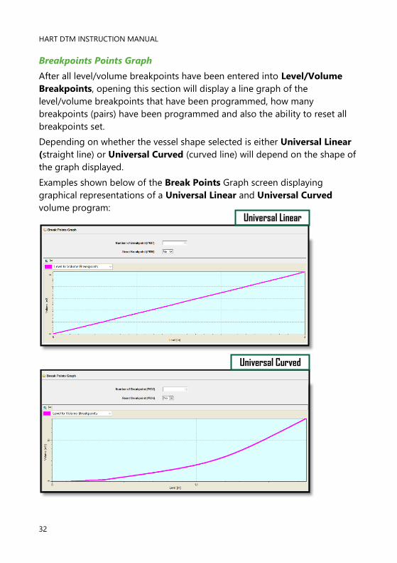
Breakpoints Points Graph
After all level/volume breakpoints have been entered into Level/Volume
Breakpoints, opening this section will display a line graph of the
level/volume breakpoints that have been programmed, how many
breakpoints (pairs) have been programmed and also the ability to reset all
breakpoints set.
Depending on whether the vessel shape selected is either Universal Linear
(straight line) or Universal Curved (curved line) will depend on the shape of
the graph displayed.
Examples shown below of the Break Points Graph screen displaying
graphical representations of a Universal Linear and Universal Curved
volume program:
Universal Linear
Universal Curved

PULSAR MEASUREMENT
33
P697 Number of Breakpoints Set
This parameter allows you to review the number of breakpoints that have
been set, without the need to access each individual one in turn, this is a
“Read Only” parameter and no values can be entered.
P696 Reset Breakpoints
This parameter allows the resetting, to the default value, of all previously set
breakpoints (P610-673), without having to access them individually. When it
is necessary to reset or amend individual breakpoints this can be achieved
by directly accessing the desired parameter (P610-673) and changing as
required.
HART commands
This section displays the generic common parameters common to all HART
certified devices. It is split into four main categories Device Variables,
Device Information, Signal Condition and Real Time Clock. If familiar
with the use of HART protocol, then it can be programmed following normal
HART procedures.
Device Variables
The parameters displayed in this section are read only.
HART DTM INSTRUCTION MANUAL
34
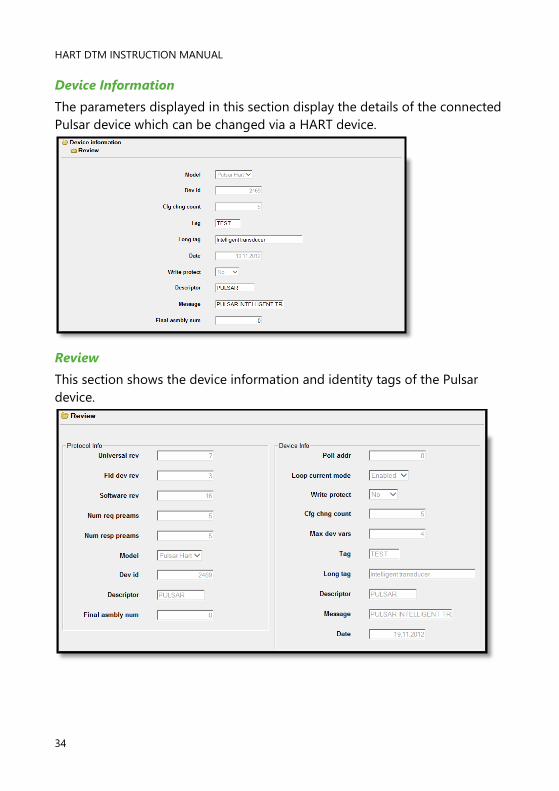
Device Information
The parameters displayed in this section display the details of the connected
Pulsar device which can be changed via a HART device.
Review
This section shows the device information and identity tags of the Pulsar
device.
PULSAR MEASUREMENT
35
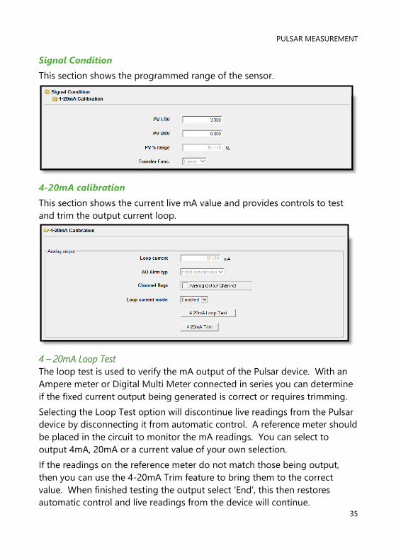
Signal Condition
This section shows the programmed range of the sensor.
4-20mA calibration
This section shows the current live mA value and provides controls to test
and trim the output current loop.
4 – 20mA Loop Test
The loop test is used to verify the mA output of the Pulsar device. With an
Ampere meter or Digital Multi Meter connected in series you can determine
if the fixed current output being generated is correct or requires trimming.
Selecting the Loop Test option will discontinue live readings from the Pulsar
device by disconnecting it from automatic control. A reference meter should
be placed in the circuit to monitor the mA readings. You can select to
output 4mA, 20mA or a current value of your own selection.
If the readings on the reference meter do not match those being output,
then you can use the 4-20mA Trim feature to bring them to the correct
value. When finished testing the output select ‘End’, this then restores
automatic control and live readings from the device will continue.

HART DTM INSTRUCTION MANUAL
36
4 – 20mA Trim
The raw 4mA and 20mA values of the output current loop can be calibrated
to an input device by altering 4mA and 20mA.
Selecting the 4-20mA Trim option will discontinue live readings from the
Pulsar device by disconnecting it from automatic control. A reference meter
(Ampere Meter, Digital Multi Meter or input device such as a PLC) should be
placed in the circuit to monitor mA readings.
The Pulsar device will begin forcing out 4mA and when correctly trimmed it
will move on to 20mA. To trim the output, simply enter the value that
ensures that 4mA or 20mA respectively are shown on the remote device and
select OK.
Real time Clock
This section allows the user to set the time and date for Pulsar devices clock.
This may be important if trending is being monitored.
Set Current Date
This format is set in DD:MM:YY, if changed it must be set in the format
displayed in the box. When finished select ‘Set Clock’.
Set Current Time
This format is set in HH:MM:SS, if changed it must be set in the format
displayed in the box.
PULSAR MEASUREMENT
37
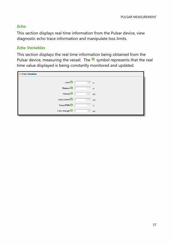
Echo
This section displays real time information from the Pulsar device, view
diagnostic echo trace information and manipulate loss limits.
Echo Variables
This section displays the real time information being obtained from the
Pulsar device, measuring the vessel. The symbol represents that the real
time value displayed is being constantly monitored and updated.
HART DTM INSTRUCTION MANUAL
38
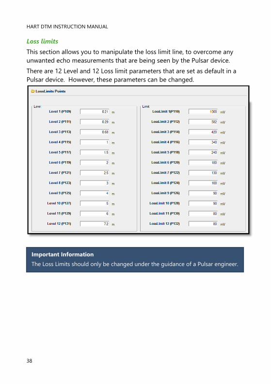
Loss limits
This section allows you to manipulate the loss limit line, to overcome any
unwanted echo measurements that are being seen by the Pulsar device.
There are 12 Level and 12 Loss limit parameters that are set as default in a
Pulsar device. However, these parameters can be changed.
Important Information
The Loss Limits should only be changed under the guidance of a Pulsar engineer.

PULSAR MEASUREMENT
39
Echo Traces
This screen displays the diagnostic trace from the Pulsar device and allows a
user to adjust the echo viewed to obtain optimum results. The layout of the
screen is as follows:
OPTION DESCRIPTION
This allows you to zoom in and out of the echo
trace
This switches between single line and multiple line
information on the trace screen.
This selects the wave form/line information to be
displayed in single line mode. Each line is
represented by a colour, choose between; Raw
Echo, Datem, Gate or Peak.
This axis represents the signal strength (in
millivolts).
This axis represents the distance in the
measurement units as defined by the Pulsar
device.
Select this to display echo trace information.

HART DTM INSTRUCTION MANUAL
40
Service
This section allows the use of service parameters in the Pulsar device, view
live trend information, and change individual parameters.
OPTION DESCRIPTION
Select this when the tank is empty, Empty Tank
Datem will result in all unwanted echoes from noise
or obstructions to be referenced out and leave the
true echo visible, when it comes back into range.
Select this to reset the Datem line to its factory set
default values. A window will be displayed when
selected to ensure the operation is to be carried out.
Select this to change the trace so that it utilises the
points set in Loss Limit Points. A window will be
displayed when selected to ensure the operation is
to be carried out.
Important Information
The above service parameters should only be changed under the guidance of a
Pulsar engineer.

PULSAR MEASUREMENT
41
Level Trending
This screen shows live trending information for the Level, Temperature and
Signal strength.
The level, Temperature and Signal strength are updated at each interval and
this can be set in the Update box. This value is in seconds and is can be
changed to a different value if required. If the trending screen is left and
returned after viewing another section, the trending information will begin
again. When the trending line reaches the end of its time period (as
depicted on the Time axis), the trending data will begin again and overwrite
the old trending information.

HART DTM INSTRUCTION MANUAL
42
Single parameter programming
This screen allows a single parameter to be viewed or changed.
Enter the parameter number that is required to be viewed and select ‘Read
from Device’. The current value of the parameter and a brief description of it
will then be displayed on the screen.
To change a parameter, select the parameter required and obtain its current
value. In the value box type in the new value required, the box will turn
yellow to indicate a change is requested. Press ‘Write to Device’ then ‘Apply’
to permanently send that change to the Pulsar device.

PULSAR MEASUREMENT
43
CHAPTER 5 TROUBLESHOOTING
This section describes many common symptoms, with suggestions as to
what to do. If the issue persists, please contact your local Pulsar distributor.
SYMPTOM WHAT TO DO
Transducer not firing. Check power supply
mA out is displaying a failed
condition, very low (3.8mA) or very
high (22mA).
No valid echo being received, and unit has
gone into fault condition. Check material
level is not out of range, sensor is
perpendicular to material surface.
Incorrect reading being obtained
for current level.
Measure actual distance from transducer
face to surface of material. Access P21, via
PC Software type in the measured distance,
and Set Parameter.
4-20mA current fixed even though
level is changing.
Poll address is above 0 and is in multi drop
mode.
Material level is consistently
incorrect by the same amount.
Check that the empty distance (P105) has
been correctly entered.
Unable to load DTM onto software
Check that you have administrator rights
on the PC being used and re-install the
DTM. A PC restart may be required after
installation as some PC’s require a restart
after software is installed.
Separated icons
No communication between the DTM and
Pulsar device. Check that all connections
are sound and there is power to the device.
Check current revision of DTM is correct,
contact Pulsar for more information
regarding this.
Disturbed Communication interrupted between DTM
and Pulsar device. Check power supply to
device.
At least one parameter value is faulty.
Check parameter settings to locate issue.

HART DTM INSTRUCTION MANUAL
44
CHAPTER 6 DISPOSAL
Incorrect disposal can cause adverse effects to the environment.
Dispose of the device components and packaging material in accordance
with regional environmental regulations including regulations for electrical \
electronic products.
Transducers
Remove power, disconnect the Transducer, cut off the electrical cable and
dispose of cable and Transducer in accordance with regional environmental
regulations for electrical \ electronic products.
Controllers
Remove power, disconnect the Controller and remove battery (if fitted).
Dispose of Controller in accordance with regional environmental regulations
for electrical \ electronic products.
Dispose of batteries in accordance with regional environmental regulations
for batteries.
EU WEEE Directive Logo
This symbol indicates the requirements of Directive 2012/19/EU regarding
the treatment and disposal of waste from electric and electronic equipment.

PULSAR MEASUREMENT
45
www.pulsarmeasurement.com
S U P P O R T @ P U L S A R M E A S U R E M E N T . C O M
Copyright © 2020 Pulsar Measurement Ltd.
Registered Address: 1 Chamberlain Square CS, Birmingham B3 3AX
Registered No.: 3345604 England & Wales
Rev 1.0
Recommended