Public Transport Tracking through Mobile Application
using Radio Frequency Identification Technology
Md. Rayhan Alam (Student ID: 09310032)
Enamul Haque (Student ID: 09310036)
Shariar Sajib (Student ID: 11110007)
Advisor: Khadija Rasul
Co-Advisor: Dr. Amitabha Chakrabarty
Department of Electronics and Communication Engineering
BRAC University, Dhaka, Bangladesh
Page | 2
DECLARATION
We hereby declare that this thesis is based on the results found by ourselves. Materials of work
found by other researcher are mentioned by reference. This thesis, neither in whole nor in part,
has been previously submitted for any degree.
Signature of Advisors
______________________
Ms. Khadija Rasul
______________________
Dr. Amitabha Chakraborty
Signature of Authors
_____________________
Md. Rayhan Alam
_____________________
Enamul Haque
_____________________
Shariar Sajib
Page | 3
ACKNOWLEDGEMENTS
This thesis gave us the opportunity to gain in-depth knowledge of radio frequency identification
and radio frequency tags from ideal and real life point of view, especially in the context of
tracking public transports and measuring the traffic density. It was a challenging opportunity for
us to work with the real hardware and construct an economical setup so that our project can be
used on regular basis by people of developing country, like Bangladesh.
We want to say thanks from the core of our heart to our advisor Ms. Khadija Rasul and co-
advisor Dr.Amitabha Chakraborty for their guidance and suggestions throughout this thesis.
They motivated and encouraged us every single moment to go forward with our goal. So it’s a
great opportunity to work with Ms. Khadija Rasul and Dr. Amitabha Chakraborty.
In the end, warm thanks to our Parents for their endless efforts and motivations to get higher
education, allowed and encourage us to study. We would not have made it so far without their
existence. We would also like to take this opportunity to thank our loving and sincere friends
,specially Wahiduzzaman Arup and ReasadAzim, who played an important role during our
studies, for their patience during this time.
Md. Rayhan Alam, Enamul Haque and Shariar Sajib
BRAC University, April 2015
Page | 4
ABSTRACT
The main aim of our thesis is to relieve general mass from the regular hassle of waiting in long
queues for public transport such as bus. We plan to do so by developing an android based cell
phone application (app) which will provide information, such as “accurate nearest location” of a
bus in a particular route and “time left” for its arrival, to the users of this app waiting in a bus
stop. The project is done by using Radio Frequency Identification (RFID) technology (radio
frequency receiver and radio frequency tags) and microcontrollers. These devices transmit
vehicles location to remote servers and based on that servers use established technique to
calculate approximate time left for bus arrival and distribute this information to the respective
clients’; the cell phone application, which we named as “Amar Bus”. We believe this free app
will make commoners’ everyday life easier and improve overall experience of commuting in
busy metro city of developing country, like Dhaka.
Page | 5
Table of Contents 1. Introduction ................................................................................................................................. 10
1.1 Motivation ................................................................................................................................. 10
1.2 Overview ................................................................................................................................... 12
1.3 Thesis Outline ........................................................................................................................... 13
2. Background Study and Literature Review .................................................................................... 14
2.1 Radio Frequency Tag ............................................................................................................... 14
2.1.1 Types of Tag: ............................................................................................................................. 16
2.1.2 RFID Reader .......................................................................................................................... 16
2.1.3 Microcontroller ...................................................................................................................... 17
2.1.4 GSM Technology .................................................................................................................. 17
2.1.5 Android .................................................................................................................................. 18
2.1.6 Web Server............................................................................................................................. 19
2.2Literature Survey ........................................................................................................................... 21
2.2.1 A GPS based automatic vehicle location system for bus .................................................... 22
2.2.2 RFID based design for vehicle location system .................................................................. 24
2.2.3 Real Time Vehicle tracking system using GSM and GPS technology – an anti-theft
tracking system ............................................................................................................................... 27
2.2.4 Vehicle Location Technologies in Automatic Vehicle Monitoring and Management
Systems ............................................................................................................................................ 30
2.2.5 Intelligent Traffic Signal Control System Using Embedded System ................................. 30
2.2.6 Commercial GPS based tracking system in Bangladesh .................................................... 33
3.Working Methodology .................................................................................................................... 35
3.1 Hardware Implementation ........................................................................................................ 36
3.1.1 Testing Equipment:............................................................................................................ 37
3.1.2 Connection Setup ...................................................................................................................... 43
3.2 Web Server Implementation ........................................................................................................ 46
Page | 6
3.3 Mobile Application Implementation ........................................................................................... 52
4.Result and Data analysis ................................................................................................................. 56
4.1 Result analysis .......................................................................................................................... 56
4.2 Result display ............................................................................................................................ 63
4.3 Data analysis ............................................................................................................................. 65
5.Conclusion ....................................................................................................................................... 70
5.1 Challenges ................................................................................................................................. 70
5.2 Future working plan ................................................................................................................. 72
References ........................................................................................................................................... 74
Page | 7
List of Figure
Figure 2.1 Passive UHF RFID tag block diagram [25]
Figure 3.1 Steps of Implementation [35]
Figure 3.2 Block Diagram of Data Transmission [36]
Figure 3.3 RFID Tag (Card Type) [38]
Figure 3.4 RFID Tag (Ring Type) [38]
Figure 3.5 RFID Reader RC522 [39]
Figure3.6 Microcontroller (Arduino UNO) [41]
Figure 3.7 Arduino Uno Schematic Design [42]
Figure 3.8 GSM Modem SIM900A [43]
Figure 3.9 Hardware test workflow [44]
Figure 3.10 Hardware Connection Model [46]
Figure 3.11 Working flow of web server [47]
Figure 3.12 Application Interface [54]
Figure 4.1 Amar Bus Application [60]
Figure 4.2 Amar Bus Interface[61]
Figure 4.3 Selection of Source and Destination From Android Application [62]
Figure 4.4 Shows the Bus List [63]
Figure 4.5 Result displayed from Amar Bus [64]
Figure 4.6 Graph of performance percentage vs range (cm) [67]
Page | 8
List of table
Table 2.1 History of RFID technology [15]
Table 2.2 Chronological Android Development Platform [18]
Table 2.3 GPS parameters and specifications [29]
Table 3.1 RFID tag Information [38]
Table 3.2 Pin Configuration of RFID Reader RC522 [40]
Table 3.3 Pin configuration of hardware devices [45]
Table 3.4 Database table for Vehicle and Tag information synchronization [48]
Table 3.5 Database table for location and GSM modem [49]
Table 3.6 BRTC Table[50]
Table 3.7 Location table (Gulshan)[51]
Table 3.8 Location table (Mohakhali) [51]
Table 4.1 Relational table for Bus and Tag [57]
Table 4.2 Relational table for Location and GSM SIM [57]
Table 4.3 Data Store at web server [58]
Page | 9
Table 4.4 Data Updated [59]
Table 4.5 RFID Tag ranging [66]
Table 4.6 Initial cost calculation [68]
Table 4.7 GPS Implementation Calculation [69]
Page | 10
1. Introduction
In this thesis we have developed a prototype system for helping public transport users of Dhaka
city to find out the location of their respective desired bus. This thesis blends in the knowledge
of electronic world to that of computer science to come up with unique solution for reducing bus
waiting time of commuters in Dhaka city. Such user friendly and easily accessible solution to our
knowledge is not yet available for the context of Bangladesh.
1.1 Motivation In Dhaka city, every morning start with a question in our mind, how long we have to wait for the
bus in queue at bus stop. Public transport is the only solution to reach our school, university,
office, business or destination. But day by day, increasing with the vehicle in the road, traffic jam
is also increasing. So, those who do not have private car, wait long hours for the vehicle in the
bus stop is the common scenario. To solve the traffic jam so many researches has been done
before, but traffic congestion problem of Dhaka city is a pressing concern, which is elevating
everyday due to the large and increasing population [1].
Automatic vehicle location (AVL) tracking has been widely researched topic. History of tracking
device will take us back to the World War II. In 1935, Scottish physicist Sir Robert Alexander
Watson-Watt discovered RADAR, which was the start of track moving particle. [2]. To track the
vehicle in the road, Global Positioning System (GPS) and General Packet Radio Service (GPRS)
technology based devices became popular. Using the GPS and GPRS based device moving
Page | 11
vehicle can be track and it helps to detect the exact location of vehicle on the earth with
longitude and latitude. On the other hand, Radio frequency Identification (RFID) invented by
Mario W. Cardullo in 1971 is also popular technology to detect the moving object on the ground.
RFID technology based RF Reader and RF tag can be used to track the transport in a particular
road [3].
Ever since introduction of Android, by Google, its various multipurpose applications have
become immensely popularity. It is a Linux Kernel based mobile operating system (OS) and it’s
source code is open for development, under the licensed owned by Google. Initially android
operating system was introduced as an user interface, based on direct manipulation, designed for
the touch screen mobile devices such as smartphone and tablet computer. But within a very short
time, android’s popularity boomed due to its low cost, user friendliness and customizable high
tech operating system.Android’s open source encouraged large number of mobile developer to
work with it among 71% of mobile app developers’ work only with android [19].
With technological advancement, vehicle tracking through the mobile application has become
common day by day application of cell phone for mass people in developed countries and it has
made human life easier and flexible. Using an android based mobile application; one can easily
find the bus for his desire destination and know the bus root for his unknown destination. Using
this application, from home or office one can find the bus arrival time; next bus status and
number of bus left to dispatch for any destination also can be check. Unfortunately such
application is yet not seen in context of Bangladesh or precisely Dhaka city, due to unruly nature
Page | 12
of traffic. Through our thesis we have taken the successful attempt for building a project that will
use RFID technology to track down bus for mass commuters in Dhaka city.
1.2 Overview To solve the long waiting in the bus stop and to reduce the suffering of the passengers of the
public transport in his particular roots, we have developed an android based mobile application
which will tell one the required time of vehicle arrival in the specific location. The passenger
will be able to get the vehicles information using his android based smartphone’s application.
Our implemented application has been aimed to be free of charge for any user.
Implementation cost is important for any project. Considering the commercial implementation
cost and maintenance cost, we planned to develop our project by using RFID tag and Receiver.
The main objectives of our thesis are:
To provide the information of public transport
Time left for its arrival
Number of buses in an specific root and number buses remain for any specific destination
Track the specific Bus and route
Low cost hardware implementation and maintenance system
Free android based user support
Alert system to make user aware of the last location of bus
Page | 13
1.3 Thesis Outline This thesis is organized in five chapters. The contents of the followingchapters are briefly
reviewed as follows
Chapter Two reviewsrelated work done in solving similar issue like us using GPS technology,
GSM technology and different traffic controlling system and also cover literature review on
commercial trackers for automated vehicle tracking system. This chapter will also focus on the
RFID history, technology and RFID components like tags, receiver and its working system,
The next chapter, Chapter Three, discusses the working methodology we used to develop the
system. Three different stage works for the whole project like hardware implementation,
webserver and database management and android based mobile application implementation.
Then Chapter Fourexplains the result of the system we found and the data analysis for the
vehicle tracking system like time left for the bus arrival and efficiency of the devices.
Finally Chapter Five includes conclusions, challenges, drawback, scopes and suggestions for
possible future work.
Page | 14
2. Background Study and Literature Review
RFID technology is currently being used in numerous applications especially for the object
identification [9]. The principles of RFID has been employed by the British in World War II to
identify their aircraft using the IFF system (Identity: Friend or Foe) [2] and it is still being used
today for the same purposes. There are two main components of this technology which are
Radio frequency identification tag and tag reader.
2.1 Radio Frequency Tag
The history of radio frequency identification technology traced back to World War II. Just few
years before the war in 1935, Scottish physicist Sir Robert Alexander Watson-Watt discovered
RADAR which had been using by The Germans, Japanese, Americans and British [2]. It used to
warn of approaching planes while they were still miles away. But it had a small lacking, it could
not identify the friends plane and enemy plane. German used the CRUDE method to identify
Page | 15
their own plane by the RADAR crew on the ground. Meanwhile, Watson-Watt developed first
active identify friend or foe (IFF) system for the British [7].
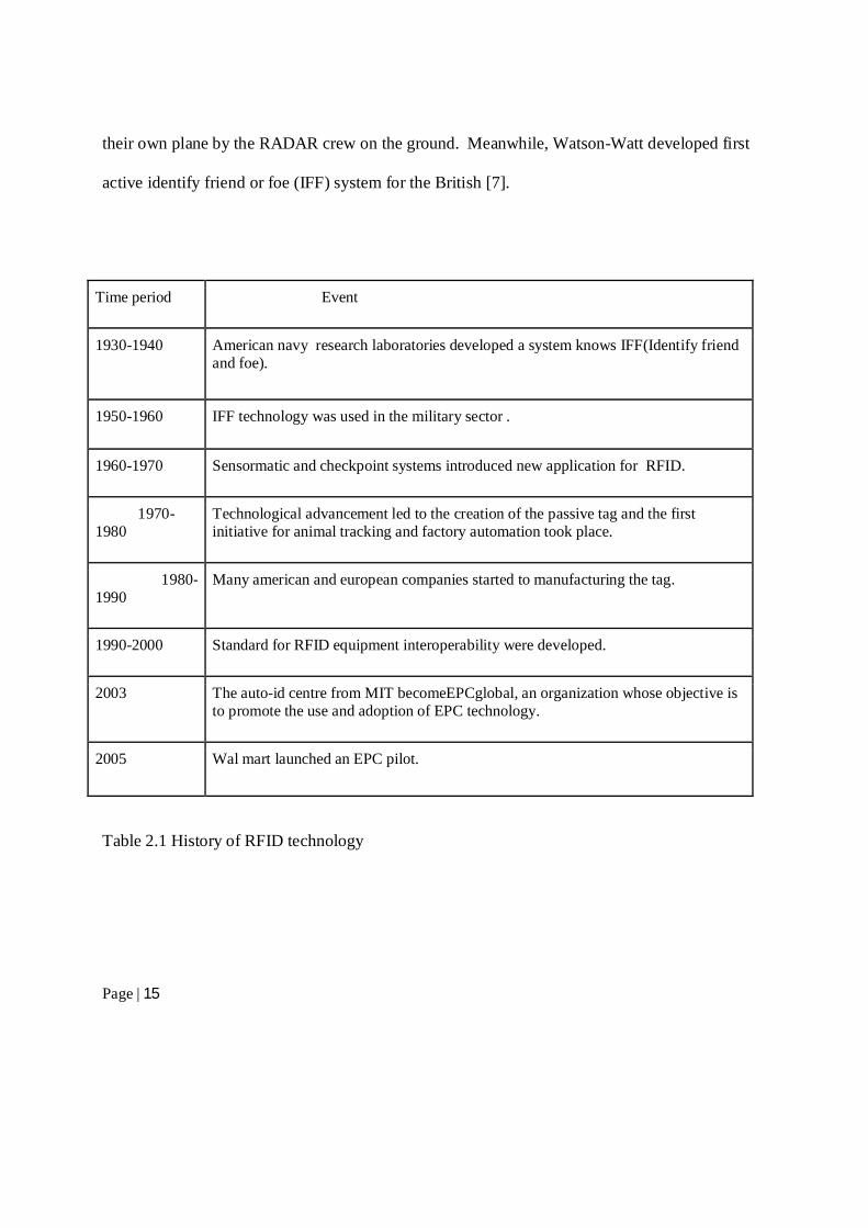
Time period Event
1930-1940 American navy research laboratories developed a system knows IFF(Identify friend and foe).
1950-1960 IFF technology was used in the military sector .
1960-1970 Sensormatic and checkpoint systems introduced new application for RFID.
1970-1980
Technological advancement led to the creation of the passive tag and the first initiative for animal tracking and factory automation took place.
1980-1990
Many american and european companies started to manufacturing the tag.
1990-2000 Standard for RFID equipment interoperability were developed.
2003 The auto-id centre from MIT becomeEPCglobal, an organization whose objective is to promote the use and adoption of EPC technology.
2005 Wal mart launched an EPC pilot.
Table 2.1 History of RFID technology
Page | 16
2.1.1Types of Tag:
There are two major types of RFID tag depending on the power supply and without power
supply [10].
Active tag: actively transmitted to a reader known as active tags.
Passive tag: Unpowered passive tags are known as passive tags.
2.1.2 RFID Reader RC522 Chip: The highly integrated read and write 13.56MHz contactless communication card
chip, which launched by the company for the "table" application of a low-voltage, low-cost,
small size of the non-contact card chip to read and write, smart meters and portable handheld
devices developed better choice [9]. The MF RC522 use of advanced modulation and
demodulation concept completely integrated in all types of 13.56MHz passive contactless
communication methods and protocols. 14443A compatible transponder signals. The digital part
of to handle the ISO14443A frames and error detection. In addition, support rapid CRYPTO1
encryption algorithm, terminology validation products. MFRC522 support series of high-speed
non-contact communication, two-way data transmission rate up to 424 Kbit/s. As new members
of the 13.56MHz reader card series of highly integrated chip family,
RFID Module:The MF522-AN module the original Philips MFRC522 chip design circuit card
reader, easy to use, low cost, and applies to the user equipment development, the reader and the
development of advanced applications, the need for the user RF card terminal design/production.
This module can be directly loaded into the various reader molds. Utilizes a voltage of 3.3V,
Page | 17
through the SPI interface simple few lines directly with any user CPU motherboard connected
communication can ensure that the module is stable and reliable work, distance card reader [9].
2.1.3 Microcontroller Arduino is an open-source electronics prototyping platform based on flexible, easy to use
hardware and software. It's intended for artists, designers, hobbyists, and anyone interested in
creating interactive objects or environments.
The project Arduino first began in 2005 at Interaction Design Institute Ivrea (IDII). Massimo
Banzi (Massimo Banzi 2012) co-founder of Arduino worked in IDII as an associate professor
who supposed to teach the students about modern interactive design in an inexpensive way. So
that everybody can bear it without facing any obstacles in their work. After that with the help of
a Columbian student named Hernando Barragán (Barragan Studio 2012) they make it simpler
and easier. At the end they make it prototype and this is how the Arduino has been given birth by
them.
2.1.4 GSM Technology
Global system for mobile (GSM) modem has a SIM card and just like mobile phone it also
subscription to a mobile operator. GSM Modem connected two devices and data is transferred.
There are three main systems of GSM networks.
The Switching System: There are five databases HLR, MSC, VLR, AUC and EIR are in the SS
which conduct various crucial operations. Call processing is the major task of switching system.
Page | 18
Mobile Switching Center (MSC) conducts with Home Location Register (HLR) and Visitor
Location Register (VLR). HLR and VLR a is used for mobile calls and routings operations.
Authentication center (AUC) provides security and the database Equipment identity register
(EIR) holds crucial information regarding mobile equipment.
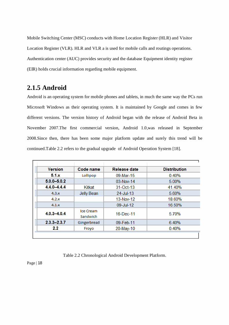
2.1.5 Android Android is an operating system for mobile phones and tablets, in much the same way the PCs run
Microsoft Windows as their operating system. It is maintained by Google and comes in few
different versions. The version history of Android began with the release of Android Beta in
November 2007.The first commercial version, Android 1.0,was released in September
2008.Since then, there has been some major platform update and surely this trend will be
continued.Table 2.2 refers to the gradual upgrade of Android Operation System [18].
Table 2.2 Chronological Android Development Platform.
Page | 19
Currently Android powers hundreds of millions of mobile devices in more than 190 countries
around the world. It is the largest installed base of any mobile platform and growing fast—every
day another million users power up their Android devices for the first time and start looking for
apps, games, and other digital content.
Android gives us a world-class platform for creating apps and games for Android users
everywhere, as well as an open marketplace for distributing to them instantly.
2.1.6 Web Server
A web server is a server that delivers content or services to end users over the Internet. It is
consists of a physical server, server operating system and software used to facilitate HTTP
communication.
The web server provides all information that a client want to know from the application. It
consists of all the information, for example when a client sends a quarry through the app to the
web server then he will get all possible information through web server. Through the web server
a client know about exact bus location, where the bus came from and where its destination is?
Secondly, from the web server client also gets to know the nearest bus arrival time from his/her
area. The web server showing all the information i.e. the bus name, bus location, possible roots,
up and down timing for exact bus, minimum time arrival time for a client from a nearest local
area.
Page | 20
Database: Database mainly defines as a set of collection of information that is organized so
that it can easily be accessed, managed and updated. A database server is a computer programme
that provides database service to other computer programmes using client-server model.
My SQL Server: Mysql server is an online based database server that provides database service
to other computer programme or computers, as defined by the client-server model [4]. It also
refers to a computer dedicated to running such a programme. There are many different types of
database server software’s some source i.e. mysql, mangoDB,postures SQL and some are
commercial software i.e. MsSQL,oracle.
The mysql software consists of the Mysql server, several utility programs that assist in the
administration of mysql database and some supporting software that the mysql server needs. The
heart of the system is the mysql server. It is the manager of the database system. If we want to
create a new database, we need to send a message to the mysql server that says for instance,
create a new database and call it new data. The mysql server then create a subdirectory in its data
directory, names the new subdirectory new data and put the necessary files with the required
format into the new data subdirectory . In the same manner, to add data to that database we need
to send massage to the mysql server, giving it in the data and telling it where we want the data to
be added.
Features of MySQL are given below:MySQL is a relational database management system. A
relational database stores information in different tables, rather than in one giant table. These
tables can be referenced to each other, to access and maintain data easily.
Page | 21
● MySQL is open source database system. The database software can be used and modified
by anyone according to their needs.
● It is fast, reliable and easy to use. To improve the performance, MySQL is multi threaded
database engine. A multithreadedapplication performs many tasks at the same time as if
multiple instances of that application were running simultaneously.
In being multithreaded mysql has many advantages. A separate thread handles each incoming
connection with an extra thread that is always running to manage the connections.Multiple client
can perform read operation simultaneously, but while writing,only hold up another client that
needs the access to the data being updated .Even through the threads share the same process
space,they execute individually and because of this separation,multiprocessor can spread the
thread across many CPU’s as long as the host operating system supports multiple CPU’s
multithreading the key featuring to supports mysql's performance design goal [7] .
2.2Literature Survey Vehicle location tracking is an ongoing popular research topic. There is plenty of work done in
this arena and many companies have commercialized some of these researches to services being
provided to people all over the world. Some of the inspiring works are as discussed below in the
following subsection.
Page | 22
2.2.1 A GPS based automatic vehicle location system for bus This paper isproposed by Akande Noah Oluwatobi, presents GPS based automatic vehicle
locator system for bus transit [11]. They presents AVL system integrated a positioning hardware
with a communication platform which used to monitor and track commuter transport in real time.
This system enables the transport management centers to observe, collect and analyze location
information about a commuter vehicle in real time. As a result an agency will able to make better
and more informed decisions by using the data and also agency can provide quicker response to
emergencies. This paper showed the benefits to the passengers mean better on time performance
and less waiting time at bus stops. The author proposed 3 basic components for the system
model. The major components are:
a) computer mapping or location display component
b) the location identification components and
c) the communication component
For the mapping purpose the author suggest google map, OpenStreetMap or mapping software.
For the case study google map maker was used to fully and effectively adjust the google map to
fit into the city. Although all those above suggested location display components are not fully
supportable.
Position detection: For the position detection this author used gps module, microcontroller
and gsm/gprs module. These devices will transmit the location of the vehicle which actually
Page | 23
track the position of the vehicle and integrated with the map and show the position. These
components are called the in vehicle-unit.
Communication component: For the communication purpose between all the components
author proposed 3 three different platforms:
a) A web based platform
b) A mobile platform
c) SMS based platform
In the Web based platform author proposed to create a web based server and a web based user
interface. The data from the In-Vehicle units will store in the database and the user will able to
access the data by using internet. Author used ASP.NET(Internet Information Server IIS) for
web server and to create web based interface with ASP.NET using C# Programming
Language.User Interface hosts a map for display the location.
In the Mobile platform they used GPRS enable mobile as a host application. By using Java 2
‘Micro Edition’(J2ME); a Java-based application platform they proposed for the mobile user. It
is a simple application helps the user to select the particular vehicles route and view their
location in real time. This application creates a way to interaction between operators and the
passengers of specific route.
Those user do not have a GPRS enable mobile device, they also get the support by using the
SMS based platform. For the simplicity of SMS based platform author proposed to create
Page | 24
specific keyword format to a short code and the desired vehicle location will be sent from the
operators to the users mobile device.
The analysis in this paper authors show how to track a vehicle by using GPS, GPRS based
hardware. The paper shows to track every individual vehicle of specific location and support the
user in three different way. The important feature of this paper is mobile application based
platform which is very useful to get the information from any place through the GPRS based
mobile device. SMS based platform also the alternative solution for the user those have not
GPRS enable mobile device. This paper established the system to track each vehicle individually
by In-Vehicle units which are GPS device, Microcontroller and GSM modem to transmit the data
to the web server.
2.2.2 RFID based design for vehicle location system
This paper is proposed by Hasan Abdulsalam Hamid, showed how to track vehicle using a new
method by simulation [5]. The author proposed to use radio frequency identification tags and
receiver to detect the location of the vehicle. The radio frequency receiver will pass the data of
the tags to the center computer system (CCS) by using antennas. In this paper author suggested
to use cheap RFID tags to track and control vehicles for the the intelligent traffic system.
The main structure of this system depending upon that every vehicle is attached with RFID tags
and when the vehicle will travel along a road, in the intersect point the receiver will read the data
Page | 25
of tags and send it to the CCS unit. So the transmitted signal will give the real time location of
the monitoring vehicles and from various point of the road the vehicle will travel and from all
intersect point of receiver unit will transmit data.
The author of the paper discussed about various types of RFID tags. Different functionality of
different tags varies and the efficiency of different tags are different. Most common tags are
Integrated Circuit with memory which is a microprocessor chip.
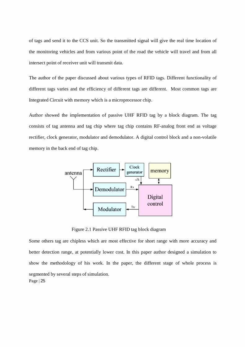
Author showed the implementation of passive UHF RFID tag by a block diagram. The tag
consists of tag antenna and tag chip where tag chip contains RF-analog front end as voltage
rectifier, clock generator, modulator and demodulator. A digital control block and a non-volatile
memory in the back end of tag chip.
Figure 2.1 Passive UHF RFID tag block diagram
Some others tag are chipless which are most effective for short range with more accuracy and
better detection range, at potentially lower cost. In this paper author designed a simulation to
show the methodology of his work. In the paper, the different stage of whole process is
segmented by several steps of simulation.
Page | 26
○ To design vehicle location system (VLS), Rifidi platform used to simulate the
connection of RFID reader with the system. Then checked the functionality and
the efficiency effects by Roads and Traffic Intersections Simulation (RTIS) before
introducing in a real-life.
○ From the traffic intersections, VLS analyzed the data received from the RFID
readers. All the data then store in the table which contained all the useful
information about the vehicles in road networks.
○ The location information of road intersection preloaded in the table which is
actually RFID readers’ position on the road. By this system author evaluated the
road status of the city. Author also showed the traffic congestion by using the
formula of average speed of vehicles in any location.
○ To calculate the routes of vehicles via use VRT algorithms used the information
of vehicle location table. In the point author showed the road network map of the
city to display the route by VLS in a table as traffic intersections.
In the paper,author proposed few future work to complete in real life by use RFID which is one
of the major growth areas of ITS. Author proposed VLS system which can be enhanced by
developing new middleware that control the system. Also showed how using different colors of
tags can help to track blacklisted vehicles in real-time.
After analysis this paper, it is clear that how RFID tags and readers can be replace the GPS or
GPRS devices unit inside the vehicle to track and how the cost can be minimize by use Alien
Page | 27
ALR 9800 RFID readers used in the important locations of the city. Author also showed passive
UHF RFID tags designing. Author also showed the different types of tags like as active tags and
passive tags with difference of range and functionality. These tags are comparatively cheap in
price and easily detectable by a RFID reader and the user can easily detect the object from short
or long distance. For our task, this system is more applicable as we are going to track the vehicle
from a static location or position.
2.2.3 Real Time Vehicle tracking system using GSM and GPS technology – an
anti-theft tracking system
In this paper, the authors KunalMaurya, Mandeep Singh and Neelu Jain proposed to use GSM
and GPS technology for antitheft tracking system [6]. This system can track wildlife, asset and
also stolen vehicle recovery. Author proposed to create web server to monitor the vehicle route
and to save the information of the route. By the system owner can determine the location even if
in the unknown route can be detect by the GPS which an advance technology. Other hand
dispatch, on board information and security can be ensuring by the system.
GPS Technology: Only the complete functional Global Navigation System (GNSS) is Global
Positioning System (GPS) which transmit precise microwave signals from at least three satellites
to calculate distance. It covers between 24 to 32 Medium Earth Orbit satellite. By the GPS
technology location, speed, direction and time can be obtained in the receiver of GPS. From at
least three satellite GPS receiver usually receive the data and using triangular technique it give
latitude and longitude of any particular position in two dimensional system. Also using at least
Page | 28
four satellite, it can give three dimensional output as longitude, latitude and altitude.
This technology was introduced by the United States Department of Defense which is officially
named as NAVSTAR-GPS. It is the key technology of getting position of any device. Although
it was initially invented to serve military purposes,later allowed to use for civilian common good
also it is free. With progress in time, changing it become one of the most useful tool for map-
making, land surveying, commerce, scientific use.
Page | 29
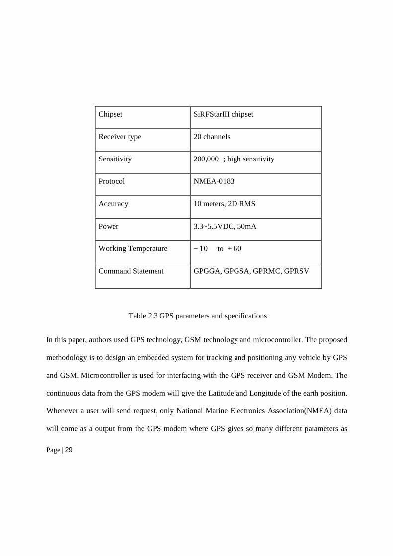
Chipset SiRFStarIII chipset
Receiver type 20 channels
Sensitivity 200,000+; high sensitivity
Protocol NMEA-0183
Accuracy 10 meters, 2D RMS
Power 3.3~5.5VDC, 50mA
Working Temperature −10�� to +60��
Command Statement GPGGA, GPGSA, GPRMC, GPRSV
Table 2.3 GPS parameters and specifications
In this paper, authors used GPS technology, GSM technology and microcontroller. The proposed
methodology is to design an embedded system for tracking and positioning any vehicle by GPS
and GSM. Microcontroller is used for interfacing with the GPS receiver and GSM Modem. The
continuous data from the GPS modem will give the Latitude and Longitude of the earth position.
Whenever a user will send request, only National Marine Electronics Association(NMEA) data
will come as a output from the GPS modem where GPS gives so many different parameters as
Page | 30
the output. The process work when users ask for the position, automatically a reply comes from
the system indicating the vehicles position. They used AT89C51 microcontroller where the code
is written in the internal memory or In ROM. The instructions are set precisely when the
microcontroller is configured.
After analyzing this paper, it is clear that, GPS and GSM modem can help to track a vehicle even
unknown route. In this paper authors showed how to get the information by saving the trajectory
of any root. This idea also can be used as ananti-theft technology, monitoring driving behavior of
employer or teen driver of parents.
2.2.4 Vehicle Location Technologies in Automatic Vehicle Monitoring and
Management Systems
In this paper authors analyzed different vehicle location technologies used in automatic vehicle
monitoring and management systems [12]. They submitted that AVL technologies have the
potential for improving fleet efficiency and providing better route planning and scheduling.
However, because there are a number of possible AVL technologies from which to choose, they
concluded that transportation managers must analyze and evaluate their system needs and
requirements before implementing any single or integrated approach to AVL system.
2.2.5 Intelligent Traffic Signal Control System Using Embedded System
In the paper, author showed few defects of traditional traffic control system which are:
a. waiting for the green light is almost same and fixed which does not really necessary
Page | 31
b. emergency cars likes fire engines and ambulances are not considered in this system
Definitions and problems description: In the paper author showed various types of traffic
light controller of traditional system. The systems are “Heavy traffic jams”, “No traffic”, “Still
need to wait”, “Emergency car stuck in traffic jam when more than one emergency can came”.
Proposed method: In this paper author proposed to build ITSC system by using AVR-32
microcontroller which has programmable flash memory. This system reduces the complexity as
there is no additional ADC required to build ITSC for high performance.
Case study 1: For the emergency cars; IR sensor network detects the emergency car and it
opens the divider gate to pass those emergency car. The rest of the cars are still under red light.so
there is no possible way to wait in the traffic jam.
Case study 2: For more than one emergency cars;in this case if more than one car come on the
signal IR sensor detects the emergency cars and let them to go by opening divider gate. here the
sensor network is used to control divider gate only to pass emergency vehicles.
The proposed ITSC system by the author, sum up hardware and software together. In the paper
author proposed genetic algorithm to find the flow of traffic. Genetics algorithm calculates the
traffic light time depending on three factors which are demand,density and flow. The formula
given by the author for green light time is :
Total time= Demands+Densities+Flows
Page | 32
Where: Demands-past data of signalized intersection;
Densities-number of present vehicle on the signal after red light.
Flows-approximate number of vehicle comes from previous signal.
After reading this paper, we understand that traditional traffic control system is not effective to
reduce traffic jam at all. The proposed ITSC system by the author is also difficult to establish in
a highly dense city like Dhaka. In the paper author only proposed an embedded system where
they didn’t show any real time traffic information. so the usefulness of this system is not clear
and the system is not fruitful for all the vehicles waiting in the traffic signal.
In this paper, authors Saloni Shah and Siddhi Patel proposed an embedded system for intelligent
vehicle theft control [14]. Modern corporate life is fully depends on transport system or vehicles.
On the contrary, various problems of using vehicles are bothering daily life.
But vehicle security enhancement and accident prevention system can be developed through
tracking and locking.By using the proposed vehicle management system user can prevent many
problems. It is also useful for detecting the location of accident. They used GPS system by using
GSM modem in this system.
In this paper, authors proposed the way to prevent car from stealing, If a car is theft,the owner
get back his car in few hours. He has to send a message to GSM module to switch off his car.
Page | 33
After getting the massage,speed of that car will be slowed gradually. When it gets off,the doors
will be locked automatically.By using the technology user can control car from stealing.
2.2.6Commercial GPS based tracking system in Bangladesh
Grameenphone Limited provides a service which is a GPS based vehicle tracking solution that
helps to get the instant location information to the vehicle owner/authorized person through
web/SMS with other flexibility. By this comprehensive solution, a user can get the real-time
position of his vehicle; control the speed limit. Grameenphone Limited added various features
with additional support such as ‘Speed violation alert’, ‘Area alarm’, ‘No-Go area’(A ‘No-go’
area can be created for the vehicles, which limit the root of the vehicles and notify the owner if
rule is violated). In addition, few more features had been added by this commercial company.
Some features of Grameen Phone tracker:
Automatic Engine Blocking by unauthorized Device Disconnection
Travel distance calculation on real time
Trip count report with travel distance
Distributor condenser
Special Sus-protector
Besides Grameenphone Limited, there are few more private company provides this service like
“Talukdar ICT Limited”, ‘Prohori Vehicle Tracking System’ by “Pi Labs Bangladesh”, a
Page | 34
tracking device named ‘GPS Tracker’ by “BD Stall”. All of these companies used GSM
technology for tracking the vehicle location and real time position. All these commercial services
used GSM technology. As these services requires GSM based tracking device to be installed
inside the vehicle thus it’s yet a costly approach, especially if this has to be done in large scale
(i.e. for tracking all the vehicles of a city for security purpose/government reason)
Page | 35
3. Working Methodology
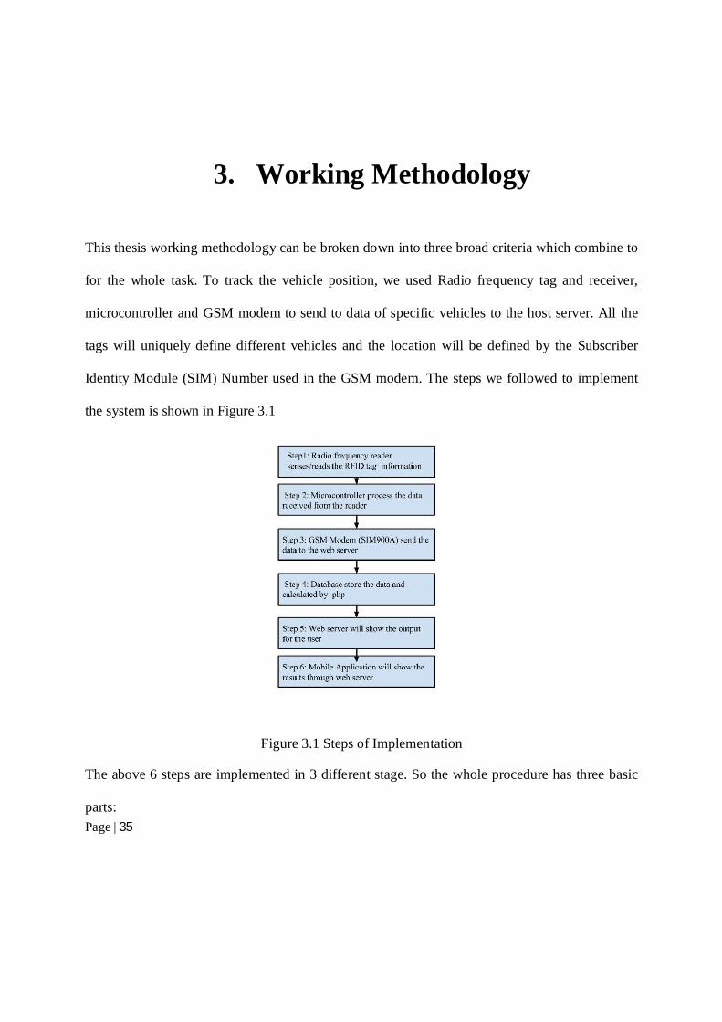
This thesis working methodology can be broken down into three broad criteria which combine to
for the whole task. To track the vehicle position, we used Radio frequency tag and receiver,
microcontroller and GSM modem to send to data of specific vehicles to the host server. All the
tags will uniquely define different vehicles and the location will be defined by the Subscriber
Identity Module (SIM) Number used in the GSM modem. The steps we followed to implement
the system is shown in Figure 3.1
Figure 3.1 Steps of Implementation
The above 6 steps are implemented in 3 different stage. So the whole procedure has three basic
parts:
Page | 36
a. Hardware Implementation
b. Web Server Implementation
c. Mobile Application Implementation
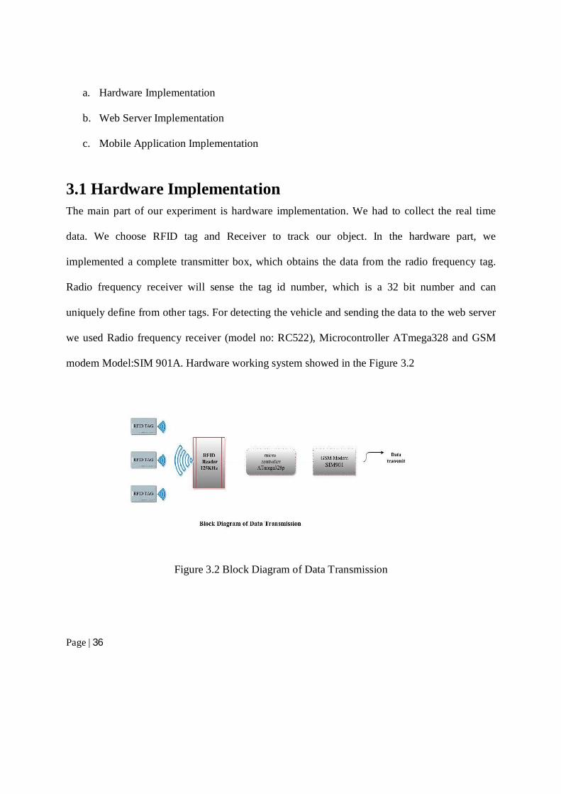
3.1 Hardware Implementation The main part of our experiment is hardware implementation. We had to collect the real time
data. We choose RFID tag and Receiver to track our object. In the hardware part, we
implemented a complete transmitter box, which obtains the data from the radio frequency tag.
Radio frequency receiver will sense the tag id number, which is a 32 bit number and can
uniquely define from other tags. For detecting the vehicle and sending the data to the web server
we used Radio frequency receiver (model no: RC522), Microcontroller ATmega328 and GSM
modem Model:SIM 901A. Hardware working system showed in the Figure 3.2
Figure 3.2 Block Diagram of Data Transmission
Page | 37
In the hardware section, we have three steps of working procedure.
1. Testing Equipment
2. Connection setup
3. Check the output
3.1.1 Testing Equipment:
For tracking and identifying the vehicle and sending the vehicle location to the desire destination
server we used 4 hardware instruments. These are Radio frequency tag, Radio frequency
receiver, Microcontroller and GSM modem.
3.1.1.1 RFID Tag:
We used basic RFID tag for our project. It is used for the presence sensing. It works in the
125kHz RF range. Main feature of these tags come with a unique 32-bit ID and are not re-
programmable. This card type tags are blank on one side, smooth, and mildly flexible. On the
other hand, ring type tags are flexible like as card type tag.
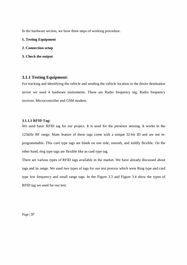
There are various types of RFID tags available in the market. We have already discussed about
tags and its range. We used two types of tags for our test process which were Ring type and card
type low frequency and small range tags. In the Figure 3.3 and Figure 3.4 show the types of
RFID tag we used for our test.
Page | 38
Figure
3.3 RFID Tag (Card Type)
Figure 3.4 RFID Tag (Ring Type)
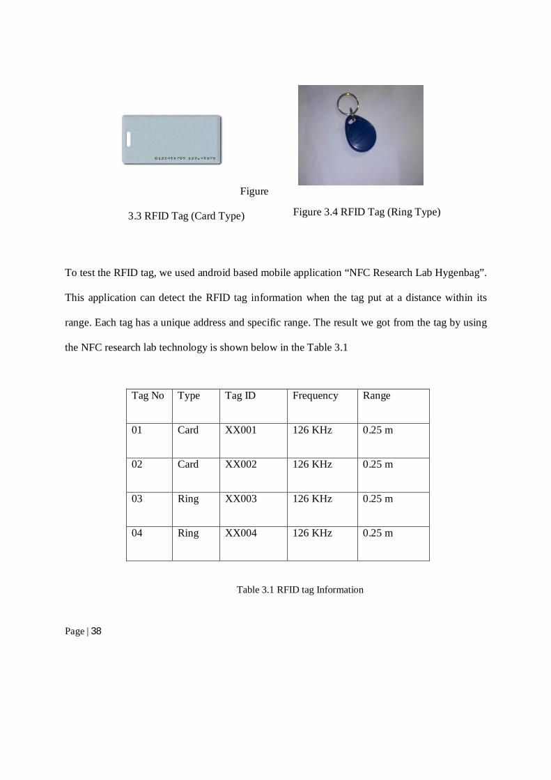
To test the RFID tag, we used android based mobile application “NFC Research Lab Hygenbag”.
This application can detect the RFID tag information when the tag put at a distance within its
range. Each tag has a unique address and specific range. The result we got from the tag by using
the NFC research lab technology is shown below in the Table 3.1
Tag No Type Tag ID Frequency Range
01 Card XX001 126 KHz 0.25 m
02 Card XX002 126 KHz 0.25 m
03 Ring XX003 126 KHz 0.25 m
04 Ring XX004 126 KHz 0.25 m
Table 3.1 RFID tag Information
Page | 39
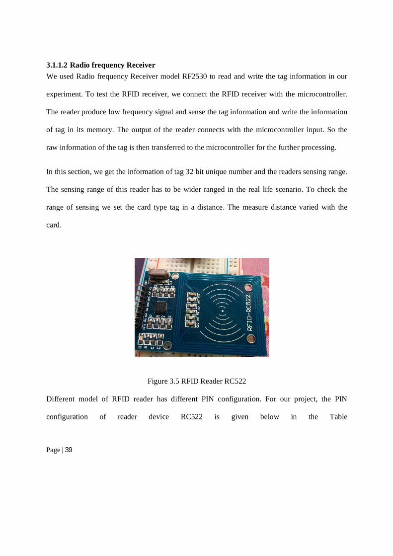
3.1.1.2 Radio frequency Receiver
We used Radio frequency Receiver model RF2530 to read and write the tag information in our
experiment. To test the RFID receiver, we connect the RFID receiver with the microcontroller.
The reader produce low frequency signal and sense the tag information and write the information
of tag in its memory. The output of the reader connects with the microcontroller input. So the
raw information of the tag is then transferred to the microcontroller for the further processing.
In this section, we get the information of tag 32 bit unique number and the readers sensing range.
The sensing range of this reader has to be wider ranged in the real life scenario. To check the
range of sensing we set the card type tag in a distance. The measure distance varied with the
card.
Figure 3.5 RFID Reader RC522
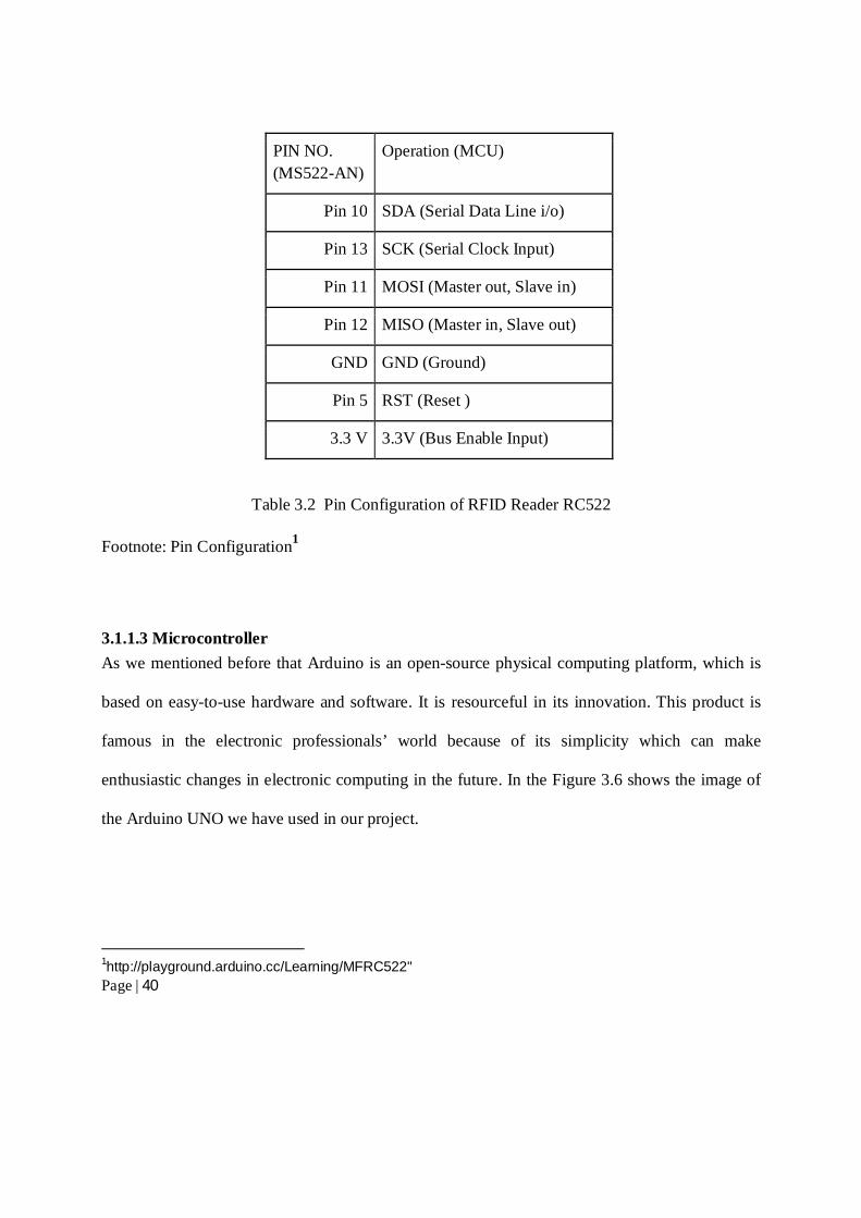
Different model of RFID reader has different PIN configuration. For our project, the PIN
configuration of reader device RC522 is given below in the Table
Page | 40
PIN NO.
(MS522-AN)
Operation (MCU)
Pin 10 SDA (Serial Data Line i/o)
Pin 13 SCK (Serial Clock Input)
Pin 11 MOSI (Master out, Slave in)
Pin 12 MISO (Master in, Slave out)
GND GND (Ground)
Pin 5 RST (Reset )
3.3 V 3.3V (Bus Enable Input)
Table 3.2 Pin Configuration of RFID Reader RC522
Footnote: Pin Configuration1
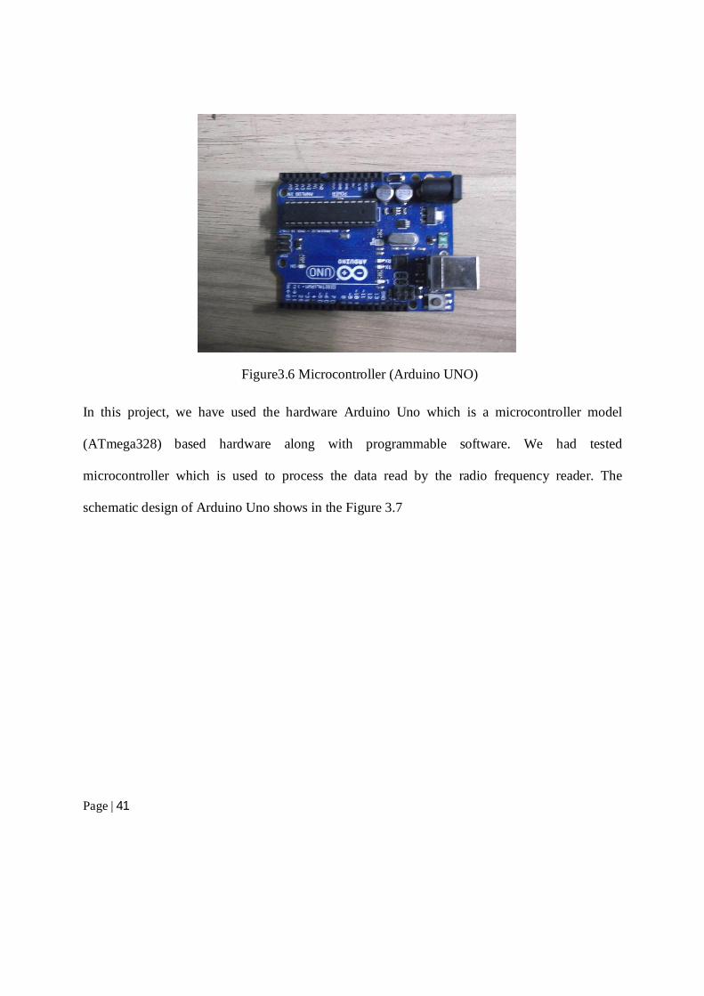
3.1.1.3 Microcontroller
As we mentioned before that Arduino is an open-source physical computing platform, which is
based on easy-to-use hardware and software. It is resourceful in its innovation. This product is
famous in the electronic professionals’ world because of its simplicity which can make
enthusiastic changes in electronic computing in the future. In the Figure 3.6 shows the image of
the Arduino UNO we have used in our project.
1http://playground.arduino.cc/Learning/MFRC522"
Page | 41
Figure3.6 Microcontroller (Arduino UNO)
In this project, we have used the hardware Arduino Uno which is a microcontroller model
(ATmega328) based hardware along with programmable software. We had tested
microcontroller which is used to process the data read by the radio frequency reader. The
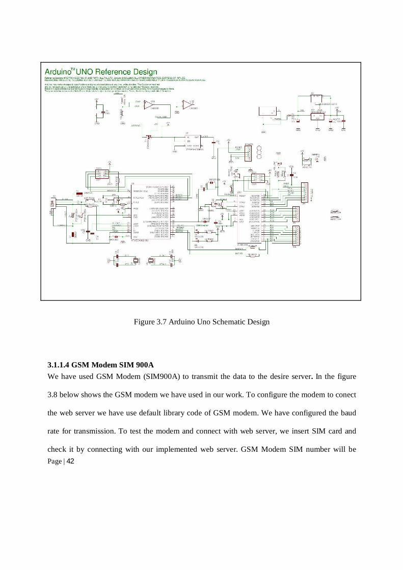
schematic design of Arduino Uno shows in the Figure 3.7
Page | 42
Figure 3.7 Arduino Uno Schematic Design
3.1.1.4 GSM Modem SIM 900A
We have used GSM Modem (SIM900A) to transmit the data to the desire server. In the figure
3.8 below shows the GSM modem we have used in our work. To configure the modem to conect
the web server we have use default library code of GSM modem. We have configured the baud
rate for transmission. To test the modem and connect with web server, we insert SIM card and
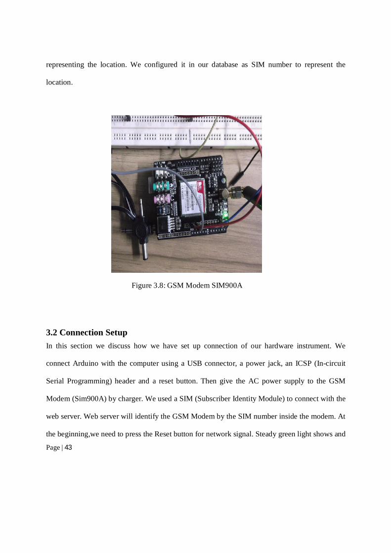
check it by connecting with our implemented web server. GSM Modem SIM number will be
Page | 43
representing the location. We configured it in our database as SIM number to represent the
location.
Figure 3.8: GSM Modem SIM900A
3.2 Connection Setup
In this section we discuss how we have set up connection of our hardware instrument. We
connect Arduino with the computer using a USB connector, a power jack, an ICSP (In-circuit
Serial Programming) header and a reset button. Then give the AC power supply to the GSM
Modem (Sim900A) by charger. We used a SIM (Subscriber Identity Module) to connect with the
web server. Web server will identify the GSM Modem by the SIM number inside the modem. At
the beginning,we need to press the Reset button for network signal. Steady green light shows and
Page | 44
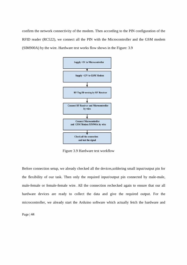
confirm the network connectivity of the modem. Then according to the PIN configuration of the
RFID reader (RC522), we connect all the PIN with the Microcontroller and the GSM modem
(SIM900A) by the wire. Hardware test works flow shows in the Figure: 3.9
Figure 3.9 Hardware test workflow
Before connection setup, we already checked all the devices,soldering small input/output pin for
the flexibility of our task. Then only the required input/output pin connected by male-male,
male-female or female-female wire. All the connection rechecked again to ensure that our all
hardware devices are ready to collect the data and give the required output. For the
microcontroller, we already start the Arduino software which actually fetch the hardware and
Page | 45
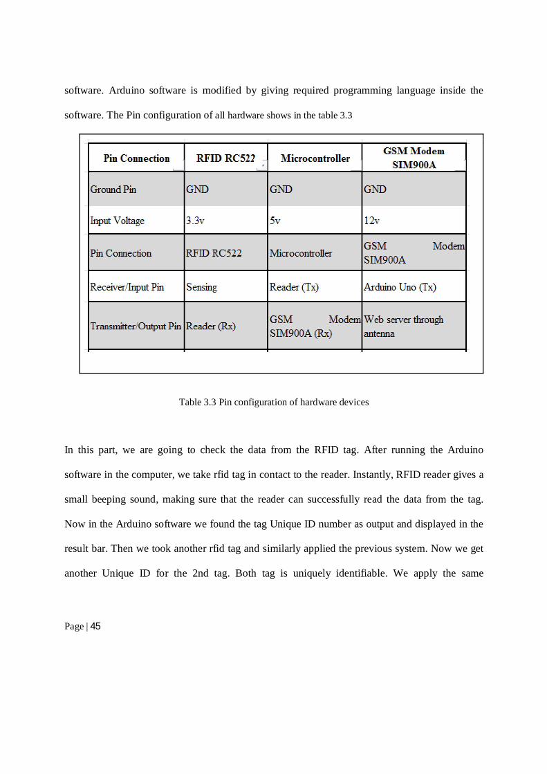
software. Arduino software is modified by giving required programming language inside the
software. The Pin configuration of all hardware shows in the table 3.3
Table 3.3 Pin configuration of hardware devices
In this part, we are going to check the data from the RFID tag. After running the Arduino
software in the computer, we take rfid tag in contact to the reader. Instantly, RFID reader gives a
small beeping sound, making sure that the reader can successfully read the data from the tag.
Now in the Arduino software we found the tag Unique ID number as output and displayed in the
result bar. Then we took another rfid tag and similarly applied the previous system. Now we get
another Unique ID for the 2nd tag. Both tag is uniquely identifiable. We apply the same
Page | 46
procedure for four other tags. So the six different tag gave us 6 different tag information what we
can read through the Arduino software.
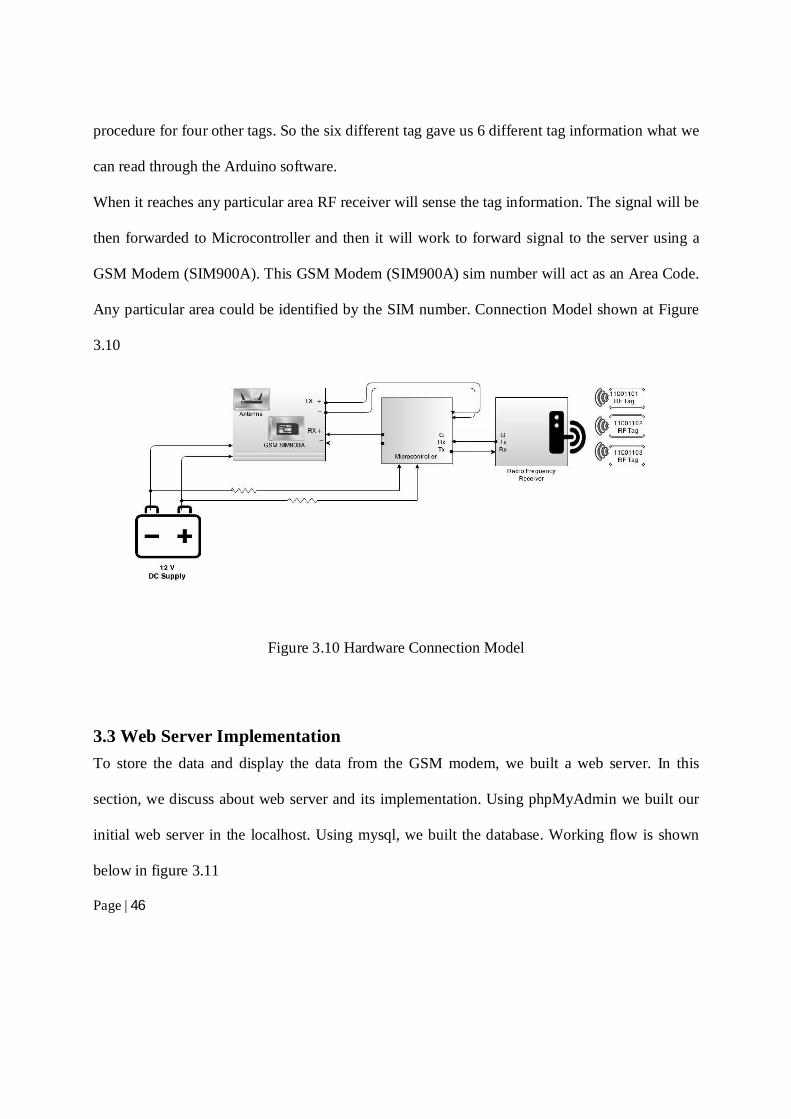
When it reaches any particular area RF receiver will sense the tag information. The signal will be
then forwarded to Microcontroller and then it will work to forward signal to the server using a
GSM Modem (SIM900A). This GSM Modem (SIM900A) sim number will act as an Area Code.
Any particular area could be identified by the SIM number. Connection Model shown at Figure
3.10
Figure 3.10 Hardware Connection Model
3.3 Web Server Implementation
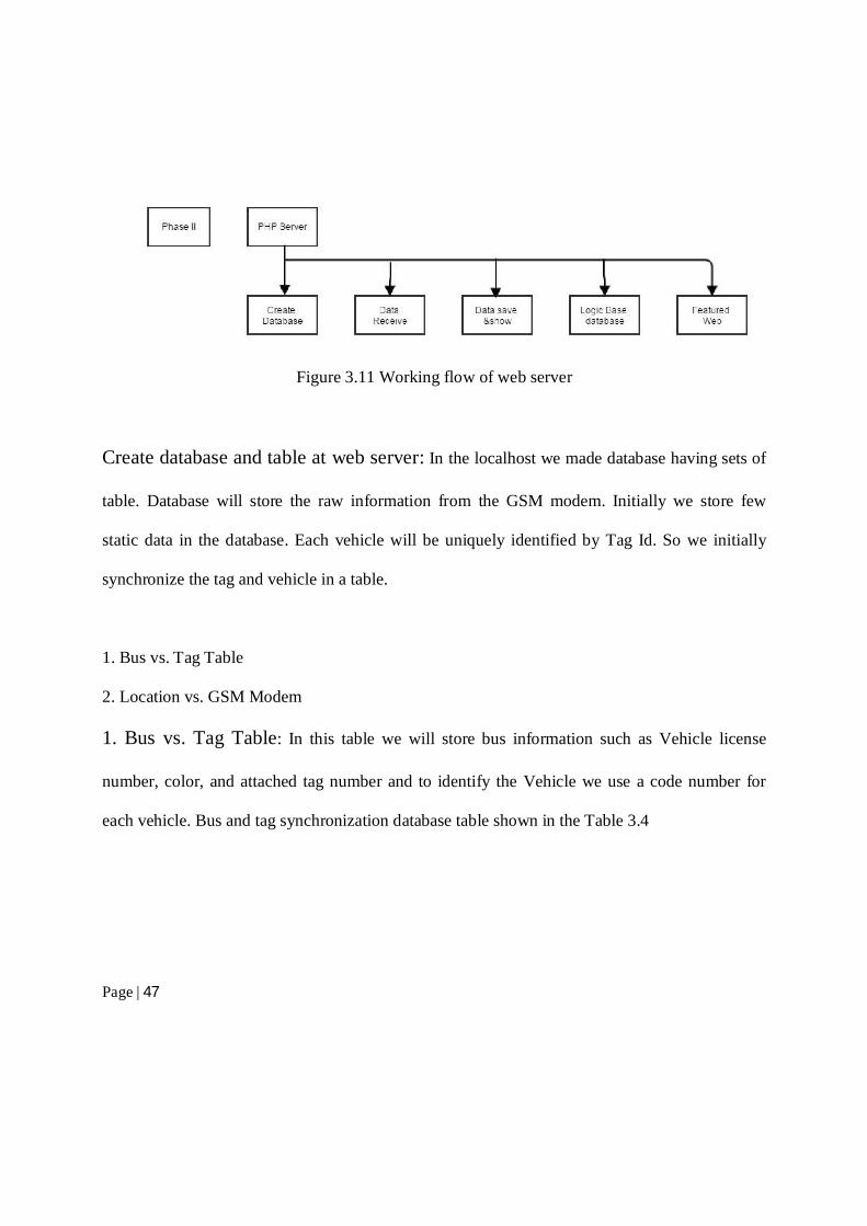
To store the data and display the data from the GSM modem, we built a web server. In this
section, we discuss about web server and its implementation. Using phpMyAdmin we built our
initial web server in the localhost. Using mysql, we built the database. Working flow is shown
below in figure 3.11
Page | 47
Figure 3.11 Working flow of web server
Create database and table at web server: In the localhost we made database having sets of
table. Database will store the raw information from the GSM modem. Initially we store few
static data in the database. Each vehicle will be uniquely identified by Tag Id. So we initially
synchronize the tag and vehicle in a table.
1. Bus vs. Tag Table
2. Location vs. GSM Modem
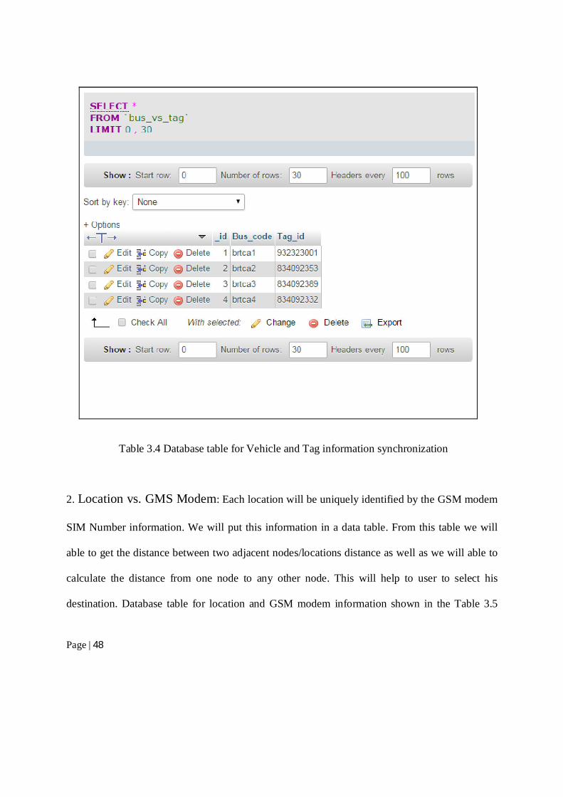
1. Bus vs. Tag Table: In this table we will store bus information such as Vehicle license
number, color, and attached tag number and to identify the Vehicle we use a code number for
each vehicle. Bus and tag synchronization database table shown in the Table 3.4
Page | 48
Table 3.4 Database table for Vehicle and Tag information synchronization
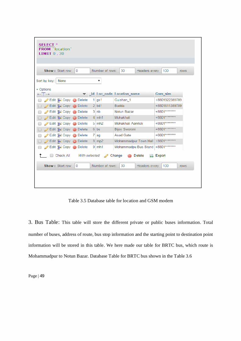
2. Location vs. GMS Modem: Each location will be uniquely identified by the GSM modem
SIM Number information. We will put this information in a data table. From this table we will
able to get the distance between two adjacent nodes/locations distance as well as we will able to
calculate the distance from one node to any other node. This will help to user to select his
destination. Database table for location and GSM modem information shown in the Table 3.5
Page | 49
Table 3.5 Database table for location and GSM modem
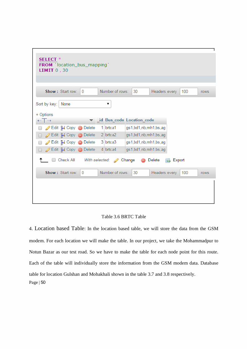
3. Bus Table: This table will store the different private or public buses information. Total
number of buses, address of route, bus stop information and the starting point to destination point
information will be stored in this table. We here made our table for BRTC bus, which route is
Mohammadpur to Notun Bazar. Database Table for BRTC bus shown in the Table 3.6
Page | 50
Table 3.6 BRTC Table
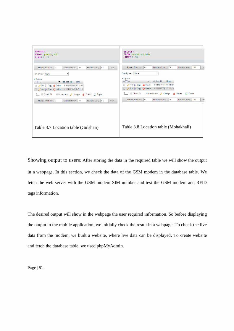
4. Location based Table: In the location based table, we will store the data from the GSM
modem. For each location we will make the table. In our project, we take the Mohammadpur to
Notun Bazar as our test road. So we have to make the table for each node point for this route.
Each of the table will individually store the information from the GSM modem data. Database
table for location Gulshan and Mohakhali shown in the table 3.7 and 3.8 respectively.
Page | 51
Table 3.7 Location table (Gulshan)
Table 3.8 Location table (Mohakhali)
Showing output to users: After storing the data in the required table we will show the output
in a webpage. In this section, we check the data of the GSM modem in the database table. We
fetch the web server with the GSM modem SIM number and test the GSM modem and RFID
tags information.
The desired output will show in the webpage the user required information. So before displaying
the output in the mobile application, we initially check the result in a webpage. To check the live
data from the modem, we built a website, where live data can be displayed. To create website
and fetch the database table, we used phpMyAdmin.
Page | 52
3.4 Mobile Application Implementation
This android application mainly focuses on the client part. The aim of this application is to make
all the information on our server side more accessible and usable for the end users with some
more additional features. The reason we took Android as the platform, is because, this is one of
the most popular and widely adopted handheld operating system right now. It is more portable
and dynamic than any other operating system. Our primary goal was to make a system, which
can echo the entire system of our server side, easily accessible, more usable and feature enriched.
At first we planned only for a web site. However, later we decided to go with Android as the
client end communication media to make our system for user friendly. We have named our app
“Amar bus”, which will be discussed feature by feature in the following sub-sections of this
chapter.
3.4.1 Technical Specification
Products or technology used to deploy this application is pretty straight forward. We used:
1. Android Studio Integrated Development Environment(IDE)
2. Android Software Development Kit (SDK)
3. Android Debugging Tool (ADT)
4. Ubuntu 14.04 as the base development environment
5. Adobe Photoshop
Page | 53
6. Java
7. Apache Web Server
8. Php
9. MySql
10. HTML 5
3.4.2 Features and Feasibilities
This android application is intended for extended use of our service in handheld devices. Users
will be able to use this application for looking and searching bus schedules. They can now easily
look for their desired bus schedule, with other details which includes, estimated time of arrival,
source to destination information. Furthermore, users will be able to set notification or alert
system for any desired bus, wherever it is close enough to the users’ locality.
3.4.3 User Interface
The User Interface of this application, called “Amar Bus” consists of Two simple buttons.
1. Select Location and Bus
2. Help
1. Select Location and Bus:Clicking on this button will take the user to the next screen/
activity where they will be presented with the in-depth query screen. Users will select the
'From', 'Destination', 'Desired Place To“Take The Bus' and 'Desired Bus'. Then user will have to
Page | 54
select 'Next'. Afterwards they will be presented with the details of that bus, which includes the
report of every 'Selected Bus'.
If wanted, user can set an alarm or notification, which will notify the user when the 'Bus' is
nearby or at least 5 minutes before.
2. Help: In this section user will have a brief overview of using this application.
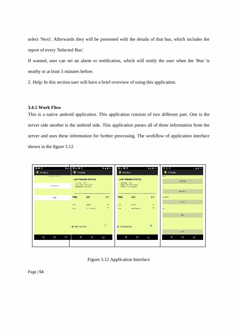
3.4.5 Work Flow
This is a native android application. This application consists of two different part. One is the
server side another is the android side. This application parses all of these information from the
server and uses these information for further processing. The workflow of application interface
shown in the figure 3.12
Figure 3.12 Application Interface
Page | 55
To parse data from the server, we used SOAP (Simple Object Access Protocol). This protocol
can efficiently get and parse web document. After parsing this data, we tokenize the whole string
to get only the required information, which includes bus names, location names and timestamps
of latest update of the bus. These again are saved to local Database. We used mysql as the
database, which is very efficient and android OS compatible.
When we get our structured data, we then use this information to show On-Screen. However, not
every single data will be displayed; rather it will show only the required information and the
relevant ones.

Page | 56
4. Result and Data analysis In the chapter, we represent our result from our project. In the previous chapter, we discussed a
demo version of how each bus can be uniquely marked with RFID tags and how RFID receiver
can be used to collect geolocation of each bus and update it to database in our server. Throughout
our experiment, initially all the stored data will be saved in the database. Then at regular interval,
database will be updated with data passed via the GSM modem and user will be shown the latest
output. Then web server will give the desire output, when an user will send request through the
android application. In the android interface display the output of Bus last location and time of
passing the receiver box.
4.1 Result analysis In one database we maintain information on buses by labeling busses, with a id referred as
‘bus_code’, and identified tags attached to them, which we refer as ‘tag_number’. In this table
Bus_code is the primary key. Also we maintain another database where each location is
separated out with id known as ‘Loc_code’ and on that spot the GSM sim of the receiver is
identified with a sim referred as ‘GSM_SIM_No’. In this database table Loc_code is the primary
key. The two databases are connected n to detect bus at different locations. Relational table for
Bus and Tag shown in Table 4.1 and Relational table for Location and GSM SIM shown in Table
4.2
Page | 57
_id Bus_code Tag_number
01 BRTCa1 932323001
02 BRTCa2 834092353
Table 4.1 Relational table for Bus and Tag
_id Loc_code GSM_SIM_No
01 gulshan +8801*********
02 mohakhali +8801*********
Table 4.2 Relational table for Location and GSM SIM
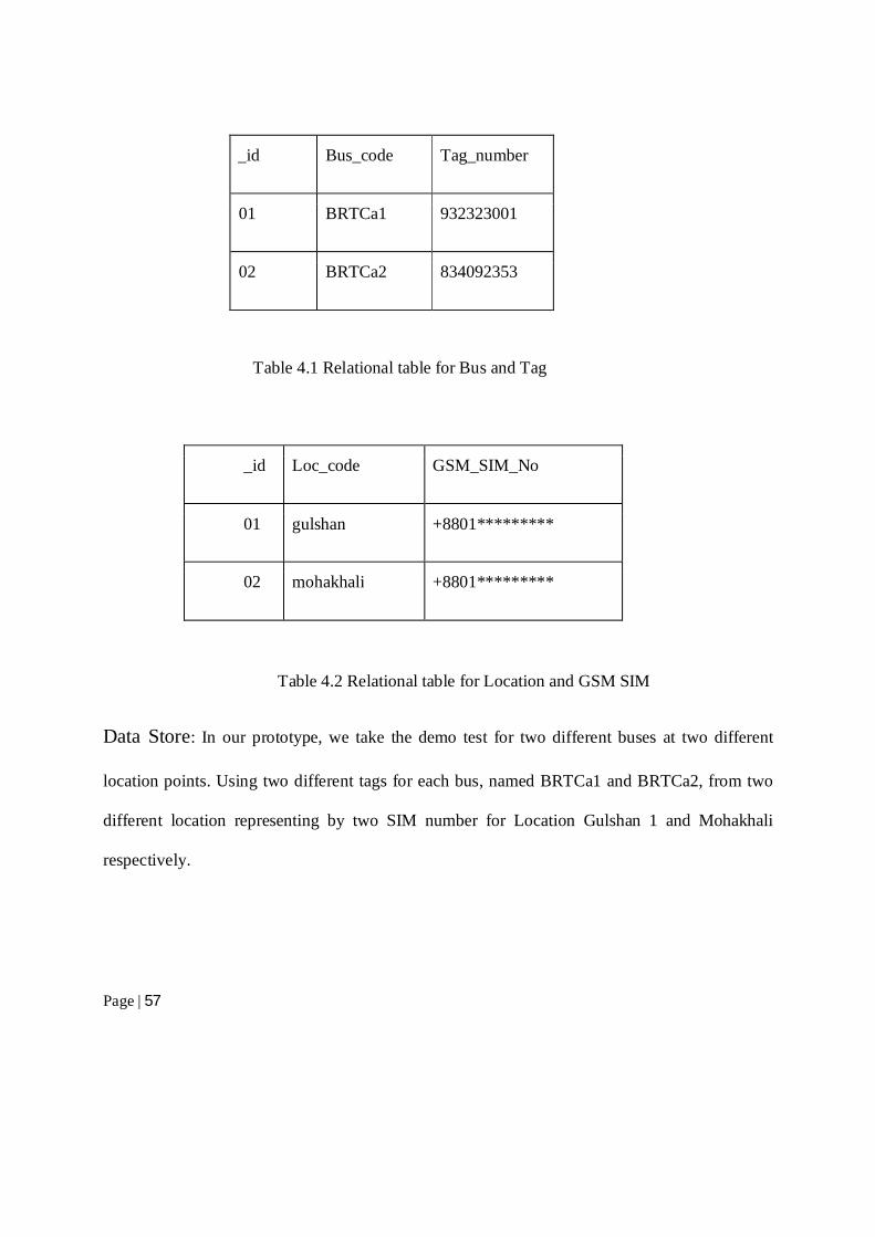
Data Store: In our prototype, we take the demo test for two different buses at two different
location points. Using two different tags for each bus, named BRTCa1 and BRTCa2, from two
different location representing by two SIM number for Location Gulshan 1 and Mohakhali
respectively.
Page | 58
Table 4.3 Data Store at web server
We have maintained a database for all information of each bus. In that set of database, individual
table store location of each bus at every instance of experiment. For example, suppose during
time 15:30:43, receiver at Mohakhali detects tag no “932323001” then the time of detection and
location of receiver will be updated at the table of “BRTCa1” table. Similarly during time
15:31:50, another receiver at location Gulshan 1 senses another tag “834092353” then
information on location and time will be updated in the table of Bus BRTCa2. From both table
we see the BRTCa1 at location Gulshan 1 and BRTCa2 at Mohakhali and reader box the passing
time 15:30:43 and 15:31:50 respectively. So we get the two different Bus information from two
different table. By this process we can the information on all Bus of BRTC in the database table.
Page | 59
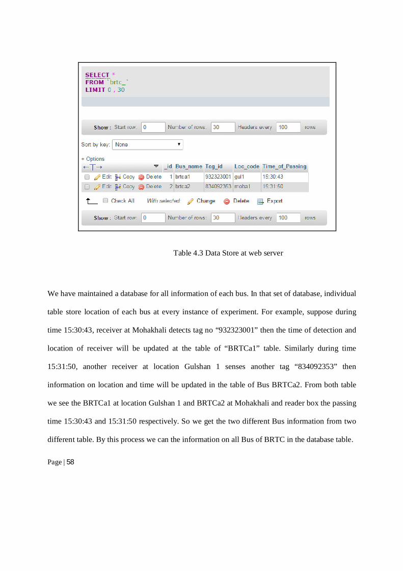
Data update: Here we repeat the test to check the update of the buses information. We sense
the tag of BRTCa1 and BRTCa2 again to see the change in database table from another address.
Here we take the same test for two tags, only changing the sensing the sensing location point. So
below the updated location table of BRTCa1 and BRTCa2 is shown in the Table 4.4
Table 4.4 Data Updated
User request: From the user side, we want to see how our project looks like. To make our
entire project accessible, we not only maintain a web interface but also an App called “Amar
bus”. This free app shows user the last location of a desired bus. When an user want to check the
bus location through Android based mobile application, initially user will select location “From”
Page | 60
and “To” from the drop down menu. It is done to select source to destination of any route. As an
response to this “get” request, user will find the all buses enlisted with the given source and
destination address as a reply from webserver. Then again select the specific Bus for destination.
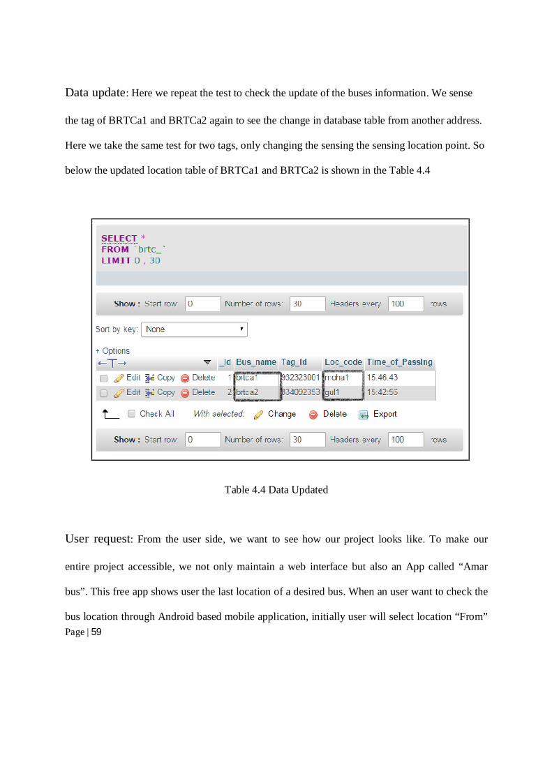
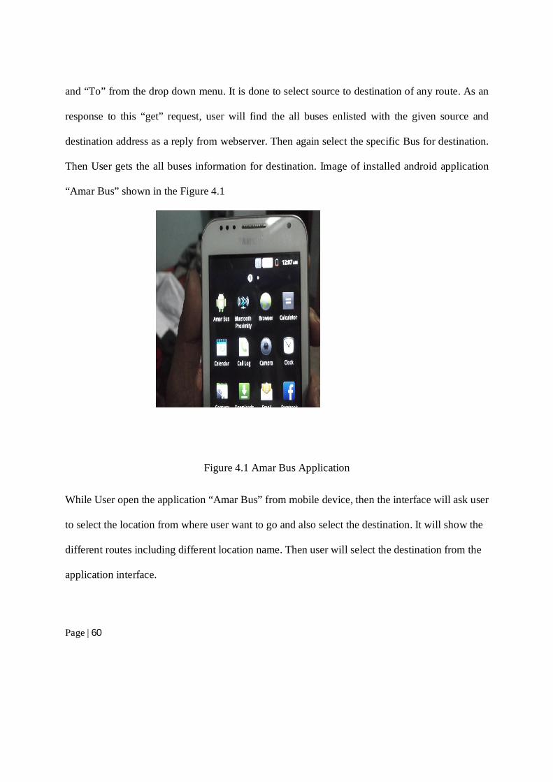
Then User gets the all buses information for destination. Image of installed android application
“Amar Bus” shown in the Figure 4.1
Figure 4.1 Amar Bus Application
While User open the application “Amar Bus” from mobile device, then the interface will ask user
to select the location from where user want to go and also select the destination. It will show the
different routes including different location name. Then user will select the destination from the
application interface.
Page | 61
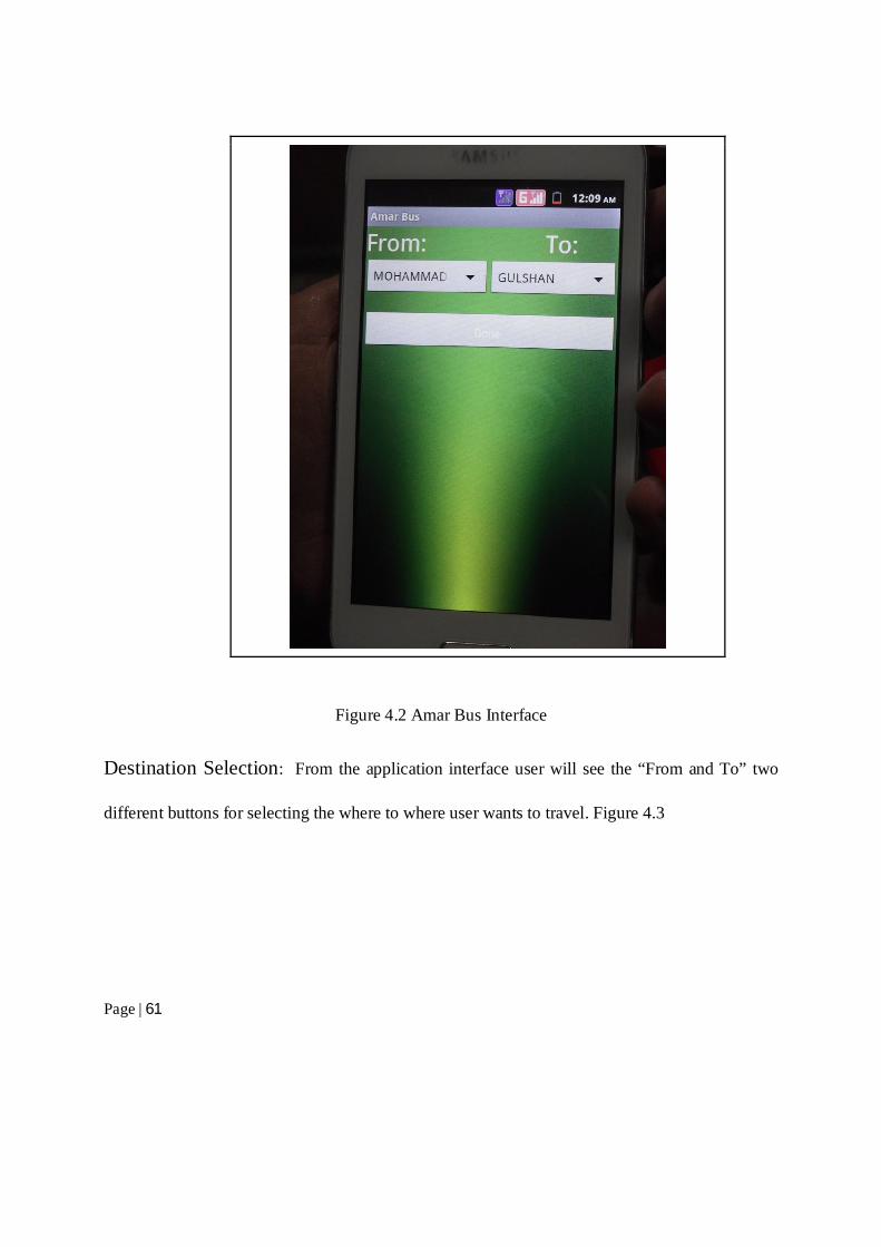
Figure 4.2 Amar Bus Interface
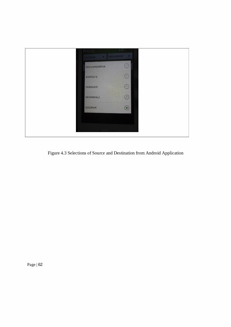
Destination Selection: From the application interface user will see the “From and To” two
different buttons for selecting the where to where user wants to travel. Figure 4.3
Page | 62
Figure 4.3 Selections of Source and Destination from Android Application
Page | 63
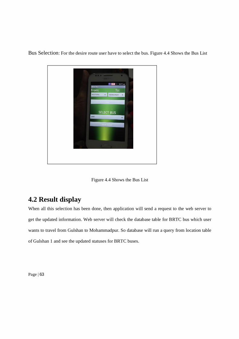
Bus Selection: For the desire route user have to select the bus. Figure 4.4 Shows the Bus List
Figure 4.4 Shows the Bus List
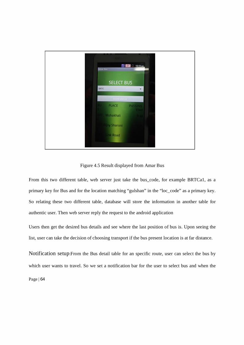
4.2 Result display When all this selection has been done, then application will send a request to the web server to
get the updated information. Web server will check the database table for BRTC bus which user
wants to travel from Gulshan to Mohammadpur. So database will run a query from location table
of Gulshan 1 and see the updated statuses for BRTC buses.
Page | 64
Figure 4.5 Result displayed from Amar Bus
From this two different table, web server just take the bus_code, for example BRTCa1, as a
primary key for Bus and for the location matching “gulshan” in the “loc_code” as a primary key.
So relating these two different table, database will store the information in another table for
authentic user. Then web server reply the request to the android application
Users then get the desired bus details and see where the last position of bus is. Upon seeing the
list, user can take the decision of choosing transport if the bus present location is at far distance.
Notification setup:From the Bus detail table for an specific route, user can select the bus by
which user wants to travel. So we set a notification bar for the user to select bus and when the
Page | 65
Bus will pass the nearest receiver, application will automatically give an alarm to alert the user to
arrive at bus stop. This will help an user to save time and relieve him/her from standing long
hour under scorching sun for the bus.
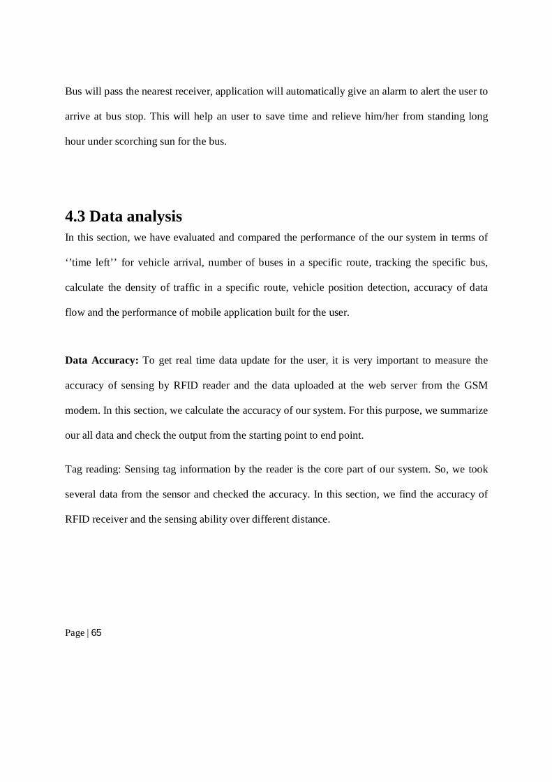
4.3 Data analysis In this section, we have evaluated and compared the performance of the our system in terms of
‘’time left’’ for vehicle arrival, number of buses in a specific route, tracking the specific bus,
calculate the density of traffic in a specific route, vehicle position detection, accuracy of data
flow and the performance of mobile application built for the user.
Data Accuracy: To get real time data update for the user, it is very important to measure the
accuracy of sensing by RFID reader and the data uploaded at the web server from the GSM
modem. In this section, we calculate the accuracy of our system. For this purpose, we summarize
our all data and check the output from the starting point to end point.
Tag reading: Sensing tag information by the reader is the core part of our system. So, we took
several data from the sensor and checked the accuracy. In this section, we find the accuracy of
RFID receiver and the sensing ability over different distance.
Page | 66
Tag ID Test No. Range of Sensing
(cm)
Reader’s
output
Maximum/Minimum point
XX001 01 5.00 Excellent Min
6.30 Good Avg
>=8.00 No output Max
XX002 02 5.50 Good Avg
6.00 Good Avg
>=7.00 No output Max
XX003
03 5.50 Excellent Min
6.10 Good Avg
>=6:50 No output Max
Table 4.5 RFID Tag ranging
Page | 67
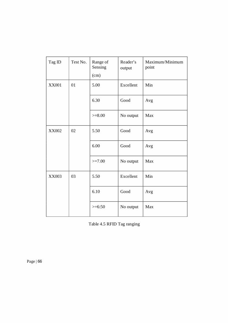
From the Table 4.5, we see the different tags sensing ranges. So the average range of sensing
from the data table we can calculate for our demo type is 5.50 cm~6.50cm for three different
tags. For our project we built the demo of the main architecture. In the main architecture for the
commercial implementation, the average sensing range will be 10m ~ 15m depending on the
width of the roads so that the accuracy of tracking can be ensured. (Only applicable for RF
Rc522)
Figure 4.6 Graph of performance percentage vs. range (cm)
Cost Analysis
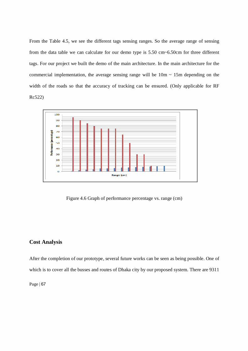
After the completion of our prototype, several future works can be seen as being possible. One of
which is to cover all the busses and routes of Dhaka city by our proposed system. There are 9311
Page | 68
registered buses and more than eight thousand minibuses in the city. Dhaka Transport Co-
ordinator Authority suggests that 149 bus routes exists currently. As 4 devices are needed per
route and each of them will cost approximately 3000BDT. To identify all busses 9311 RFID tags
will be needed where each will cost 25 taka. So initial implementation cost will be roughly 2.02
million BDT.
Comparing to other tracking Services: Of course, there are multiple number of vehicle
tracking services are in business right now and all of them are using GPS technology. A
moderate GPS device for tracking costs around 8000 BDT with monthly fee of 500 BDT
average. So to cover all the busses, 72.48 million taka will be needed. Comparing it to our
proposed system, it is nearly 36 times costly.
Instruments Cost (BDT)
per piece
Quantity (pieces) Individual Total
(BDT)
Compacted Device 3000 596 1788000
Tag 25 9311 232775
Total Cost 2,020,775
Monthly Bandwidth fee
1000 596 596,000
Table 4.6 Initial cost calculation
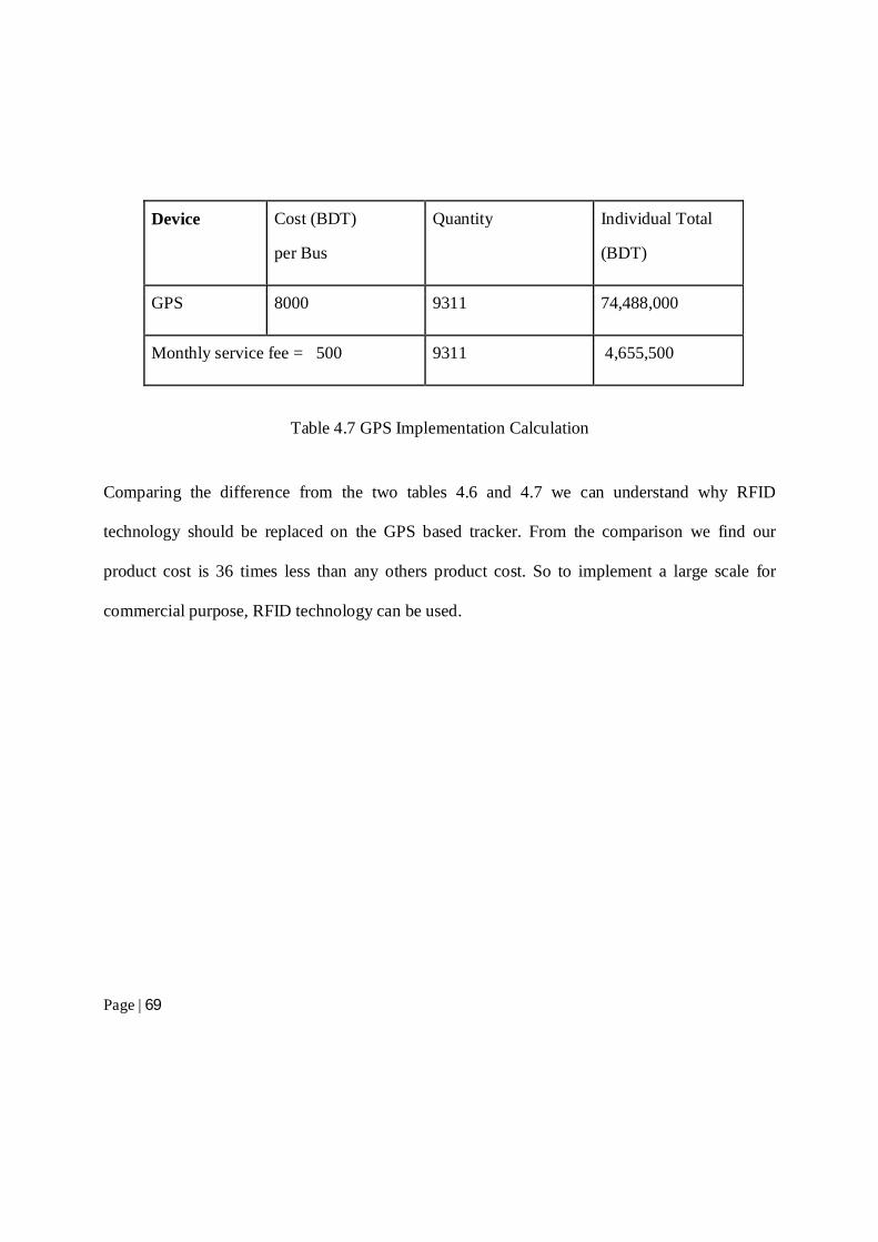
Page | 69
Device Cost (BDT)
per Bus
Quantity Individual Total
(BDT)
GPS 8000 9311 74,488,000
Monthly service fee = 500 9311 4,655,500
Table 4.7 GPS Implementation Calculation
Comparing the difference from the two tables 4.6 and 4.7 we can understand why RFID
technology should be replaced on the GPS based tracker. From the comparison we find our
product cost is 36 times less than any others product cost. So to implement a large scale for
commercial purpose, RFID technology can be used.
Page | 70
5. Conclusion
The system discussed so far is a prototype work. This report gives an in depth views of all the
tools, hardware equipment, software and data used to build the structure;we implemented this
system to provide the service to the public bus passengers. Three different phases work had been
put together for this prototype structure. Our developed mobile application “Amar Bus” is now
capable to show the updated data from the web server. To implement the projection real life, lots
of improvement in case of data, tools and parameters are required . Our implemented system can
be helpful to provide useful information for an user. Our motivation was to provide a service to
the android based mobile users, but our actual goal will be accomplished, when in real life public
bus user will be benefited by using this application on day to day basis. To fulfill this goal,
weneed more fund to build a real time product and more data to control the traffic system.
5.1 Challenges To implement this product we had to face a lot to challenges. We had three phase of
implementation including hardware product build, web server and database management and
android application. Below we discuss challenges faced at each step.
Configuration of Hardware devices:
Page | 71
In the hardware part, we worked with radio frequency reader and tag, microcontroller and GSM
Modem SIM900A. We had to configure these to build our prototype model. It was difficult to
upload real time data from GSM modem to web server. Data congestion error and data upload
delay was a real challenge for us. We successfully reduced the data upload delay.
Range of RFID Reader:
In our project, we used RFID active tags and reader RC522, which was low frequency tag reader.
So to develop a real world product we can change this reader. Only frequency make the
difference between a low and high range reader.
So this range problem can be reduced by using same reader having higher ranged frequency
detectors.
Android application development:
To develop our android application “Amar Bus”, we had to faced difficulty as well. It is a model
of the realistic future application we plan to come up with some day. We have to include more
fields to provide better user interface. We planned to add a notification button, which will be
helpful to give a notification on bus location to an user.
Monetary Constraints:
To develop a real world product, we need a large amount of fund. So with the some fund we
made this prototype product. If we get fund from government or other private authority, we can
implement a real time product.
Page | 72
Scalability issue:
Our entire project did not get the opportunity to be tested on entire Dhaka city BRTC bus routes.
Also due to lack of expertise on database manipulation so redundancy remains among our tables,
which can be easily overcome by using normalization techniques like BCNF.
5.2 Future working plan
By using this product, we can be able to provide more services than just bus arrival time. To fulfill our
goal we have some future working plan, which we discuss below.
Traffic Control:
Measure the density of traffic from the database. This system will be helpful to get the total
vehicle moving in an area. So we can use this system for the improvising the traffic control
system of any city like Dhaka.
Reducing Traffic Congestion:
When we are able to count the vehicle from any point, then we must able to implement an
intelligent system, which will store data of any area and automatically control traffic signal based
on traffic density
VIP, Ambulance and Emergency services:
Design the traffic system for the VIP, Ambulance and all other emergency services like Fire-
service to avoid heavy traffic jam and save time of those who have higher priority.
Page | 73
Anti-theft and Unwanted Vehicle track:
In future we plan to include feature which will enable one to select every single public and
private vehicle for tracking purpose . An example selecting vehicle who does not obey the traffic
rules and detecting vehicle driven by snatcher.
Overall, the greater goal of this thesis is to start a way to make mass people life easy. Its only in
prototype level but we look forward to carry our research further and make it a realistic
application.
Page | 74
References
[1] Mahmud, K., Gope , K., &Chowdhury, S. M. (2012). Possible Causes & Solutions of Traffic
Jam and Their Impact on the Economy of Dhaka City. Journal of Management and
Sustainability, 2(2), 112-135.
[2] R. Want, “RFID Explained A Primer on Radio Frequency Identification Technologies”,
Morgan & Claypool Publishers, DOI 10.2200/S00040ED1V01200607MPC001, Vol. 1, No. 1,
USA, 2006.
[3] C. M. Roberts, "Radio Frequency Identification (RFID)", Computers & Security, Vol. 25,
Issue 1, Feb. 2006. Elsevier Ltd.,DOI:10.1016/j.cose.2005.12.003, 2006.
[4] M. M. Alwan, “RFID - Based SQL Server for Library Systems”, M.Sc Thesis, Computer
Engineering Department, Nahrain University, Iraq, 2007.
[5] Hamid, H. A. (2011). Design of an rfid based vehicle location system. Al-Nahrain University,
M. Sc in Computer Science.
[6] Maurya , K., Singh, M., & Jain, N. (2010). Real Time Vehicle tracking system using GSM
and GPS technology – an anti-theft tracking system. International Journal of Electronics and
Computer Science Engineering, 2, 57-63.
[7] A. A. Pandit, J. Talreja and A. K. Mundra, "RFID Tracking System for Vehicles RTSV",
Proc. of the IEEE First International Conference on Computational Intelligence, Communication
Page | 75
Systems and Networks, CICSYN '09, ISBN: 978-0-7695-3743-6, pp. 160-165, Indore, India,
2009.
[9] H. Lehpamer,”RFID Design Principles”, Artech House Microwave Library, INC., ISBN 13:
978-1-59693-194-7, USA, 2008
[10] B. Manish and M. Shahram, " RFID Field Guide: Deploying Radio Frequency Identification
Systems”, Prentice Hall PTR, ISBN: 0-13-185355-4, Pearson Education, USA, 2005.
[11] C. H. Li, "Automatic Vehicle Identification AVI System Based on RFID", Proc. of the IEEE
International Conference on Anti-Counterfeiting Security and Identification in Communication
(ASID), ISBN: 978-1-4244-6731-0, pp. 281-284, Chengdu, China, 2010.
[12] John M. Watje, Denis Symes& ROBERT S. OW ,(2007), “ Vehicle Location Technologies
in Automatic Vehicle Monitoring and Management Systems” IVHSJournal, Volume 1, Issue 3,
Pages 295-303.
[13] Rotake, D., & Karmore, P. S. (2012). Intelligent Traffic Signal Control System Using
Embedded System. International Knowledge Sharing Platform, 3(5).
[14] Shah, S., & Patel, S. (December 2014). Intelligent Vehicle Theft Control using Embedded
System. International Journal of Computer Applications, 107(19).
[15] Vehicle Tracking System. (n.d.). Retrieved 01 15, 2015, from Talukder ICT Ltd:
http://www.talukderict.com/vehicle_tracking_new.php
[16] Vehicle Tracking System (VTS). (n.d.). Retrieved 01 17, 2015, from Pi Labs Bangladesh
Ltd:
http://www.pilabsbd.com/index.php/products/automobile/vehicle-tracking-system-vts.html
[17] Vehicle Tracking. (n.d.). Retrieved 12 26, 2014, from Grameenphone:
Page | 76
http://www.grameenphone.com/personal/vas/mobile-services/vehicle-tracking
[18] "Android Developers: Dashboards". android.com. April 6, 2015. Retrieved April 8,2015.
[19] Douglas Perry (July 16, 2011). "Google Android Now on 135 Million Devices".
Tomsguide.com. Retrieved May 1, 2013.
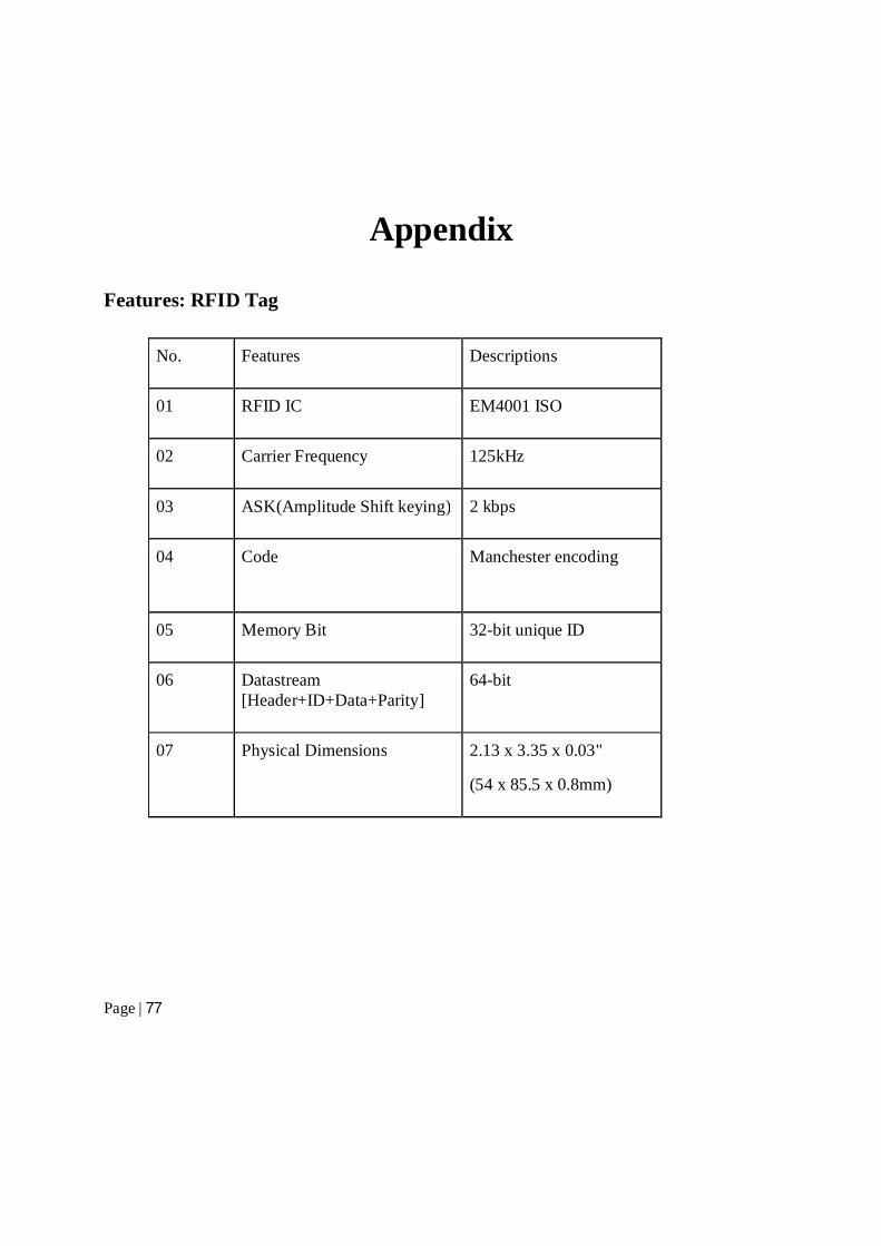
Page | 77
Appendix
Features: RFID Tag
No. Features Descriptions
01 RFID IC EM4001 ISO
02 Carrier Frequency 125kHz
03 ASK(Amplitude Shift keying) 2 kbps
04 Code Manchester encoding
05 Memory Bit 32-bit unique ID
06 Datastream [Header+ID+Data+Parity]
64-bit
07 Physical Dimensions 2.13 x 3.35 x 0.03"
(54 x 85.5 x 0.8mm)
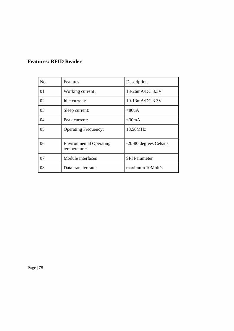
Page | 78
Features: RFID Reader
No. Features Description
01 Working current : 13-26mA/DC 3.3V
02 Idle current: 10-13mA/DC 3.3V
03 Sleep current: <80uA
04 Peak current: <30mA
05 Operating Frequency: 13.56MHz
06 Environmental Operating temperature:
-20-80 degrees Celsius
07 Module interfaces SPI Parameter
08 Data transfer rate: maximum 10Mbit/s
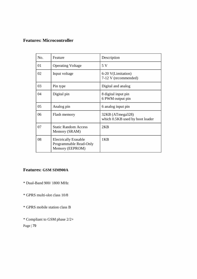
Page | 79
Features: Microcontroller
No. Feature Description
01 Operating Voltage 5 V
02 Input voltage 6-20 V(Limitation) 7-12 V (recommended)
03 Pin type Digital and analog
04 Digital pin 8 digital input pin 6 PWM output pin
05 Analog pin 6 analog input pin
06 Flash memory 32KB (ATmega328) which 0.5KB used by boot loader
07 Static Random Access Memory (SRAM)
2KB
08 Electrically Erasable Programmable Read-Only Memory (EEPROM)
1KB
Features: GSM SIM900A
* Dual-Band 900/ 1800 MHz
* GPRS multi-slot class 10/8
* GPRS mobile station class B
* Compliant to GSM phase 2/2+
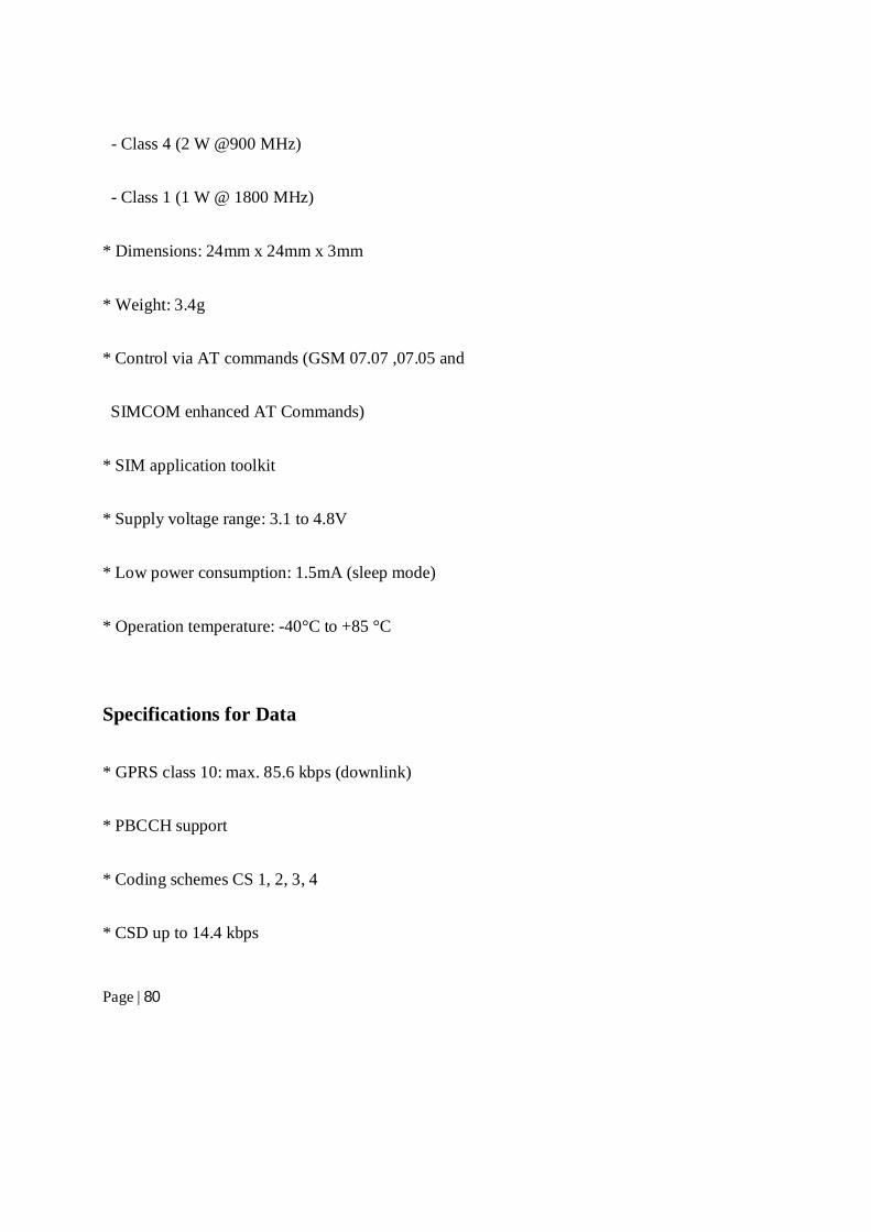
Page | 80
- Class 4 (2 W @900 MHz)
- Class 1 (1 W @ 1800 MHz)
* Dimensions: 24mm x 24mm x 3mm
* Weight: 3.4g
* Control via AT commands (GSM 07.07 ,07.05 and
SIMCOM enhanced AT Commands)
* SIM application toolkit
* Supply voltage range: 3.1 to 4.8V
* Low power consumption: 1.5mA (sleep mode)
* Operation temperature: -40°C to +85 °C
Specifications for Data
* GPRS class 10: max. 85.6 kbps (downlink)
* PBCCH support
* Coding schemes CS 1, 2, 3, 4
* CSD up to 14.4 kbps
Page | 81
* USSD
* Non transparent mode
* PPP-stack
Recommended