Protection ProjectStage One
Colin Hepton
Foundation Engineer
North East 2 / Keadby Team
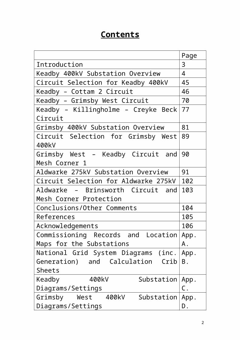
Contents
PageIntroduction 3Keadby 400kV Substation Overview 4Circuit Selection for Keadby 400kV 45Keadby – Cottam 2 Circuit 46Keadby – Grimsby West Circuit 70Keadby – Killingholme – Creyke Beck Circuit 77Grimsby 400kV Substation Overview 81Circuit Selection for Grimsby West 400kV 89Grimsby West – Keadby Circuit and Mesh Corner 1 90Aldwarke 275kV Substation Overview 91Circuit Selection for Aldwarke 275kV 102Aldwarke – Brinsworth Circuit and Mesh Corner Protection
103
Conclusions/Other Comments 104References 105Acknowledgements 106Commissioning Records and Location Maps for the Substations
App. A.
National Grid System Diagrams (inc. Generation) and Calculation Crib Sheets
App. B.
Keadby 400kV Substation Diagrams/Settings App. C.Grimsby West 400kV Substation Diagrams/Settings App. D.Aldwarke 275kV Substation Diagrams/Settings App. E.
2

Introduction
For this project, three substations have been chosen from the local area that satisfy the following criteria:
1. Double Busbar2. Four-Corner Mesh3. Single Switch
These are Keadby 400kV, Aldwarke 275kV and Grimsby West 400kV substations respectively.
For each substation mentioned, the aim of this project is to:
Describe the substation, noting any unusual features about the substation and the background to each substation from inception to present day.
Note the protections at each substation associated with the primary plant at each substation, including (but not necessarily restricted to) each feeder, supergrid transformer, busbar and reactive plant. This will include an inventory of each relay at each substation associated with protection and a selective explanation of how these work.
From these notes, a sample to be taken from each substation and these described more thoroughly to indicate details including type, manufacturer, operation, tripping and intertripping and so on. This will include settings (and, where available, explanations for these settings) for each protection system examined.
This project will include a multitude of sources of information, which will be referenced. Also included in appendices are location maps for each substation mentioned, as well as circuit diagrams, settings, etc.
3

Keadby 400kV Substation
Overview
Keadby 400kV substation is located near the steel town of Scunthorpe, on the opposite bank of the Trent and is sited near a power station (Keadby Power, generating at 15.5kV) and a railway line (notably used by local trains between Cleethorpes and Doncaster and the Trans-Pennine express service to Manchester). There is also a 132kV substation within a 10-minute walk, operated by YEDL, the local Distribution Network Operator. There is also a former 275kV substation site (indications are a compound with a concrete area, a sign and not much else) situated opposite the 400kV site which can be effectively ignored (See Appendix A for a local map of this substation).
For the most part, farmland and the power station surround the substation, but there are two or three houses nearby close enough to be a consideration when dealing with certain circumstances such as rise of earth potentials.
Keadby 400kV is also an Economic Key Point when considering the system at large – which highlights the importance of this substation to the National Grid. From the map in Appendix B it can be seen that there is a lot of generation in the local vicinity (South Humber Bank, Killingholme (2 power stations), Cottam, West Burton, Drax to mention a few) and Keadby serves as part of the North-South power flow which is vital to the electricity supplies of the country. Taking the generation into consideration, it is interesting to note that, whilst the vast majority of the power stations in the area are Combined Cycle Gas Turbines (CCGT), at Humber Refinery (Conoco-Phillips) there is a Combined Heat and Power unit (CHP) – one of only two in the country (the other being at Shotton in the North West).
To put a number on the importance of Keadby in terms of generation – if every power station directly connected (via overhead lines) to Keadby was on full load, sending everything it had to Keadby (unlikely event, but serves to underline the sheer amount of power in the area) then 11782MW of power could flow into Keadby 400kV.
Some of the key features of Keadby 400kV substation is the fact that it is an outdoor substation, containing a mixture of Air based switchgear and Gas (SF6) based switchgear, and two Quadrature Boosters, which are located on the Cottam circuit. It is a double busbar substation with a wrapped around reserve bus and this along with the general layout of the substation can be found in appendix C. Over the years, the substation has been extended (again, most notably in recent times with the addition of the quadrature boosters) and still has spare bays for further extension if required. Another feature of the substation is that it is quite compact for a 400kV substation with this many circuits and certain outages can cause problems especially when considering work to be done near oversailing conductors.
The circuits at the substation are listed on the next page:
4

Circuit Approximate date of Commissioning and supporting details
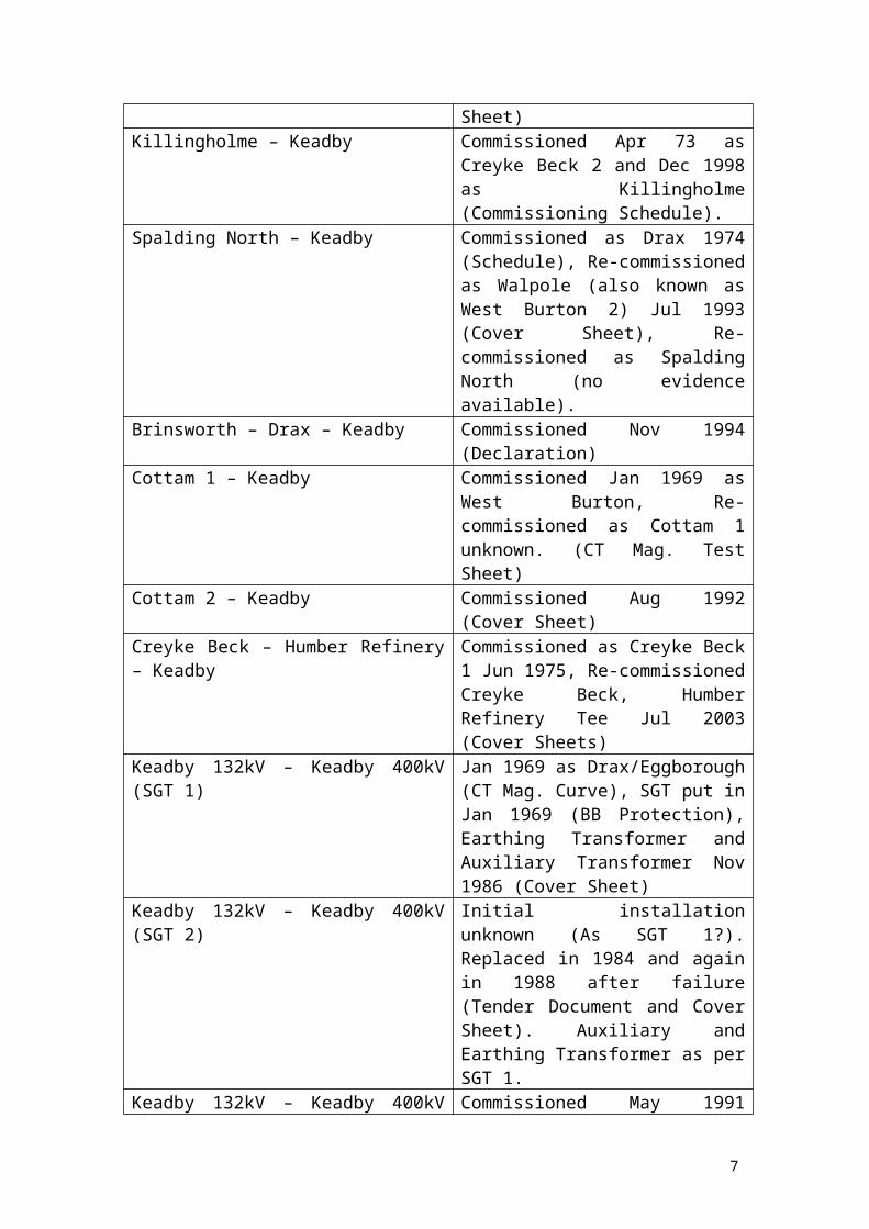
Creyke Beck – Killingholme – Keadby Jan 1969 as Grimsby West 2 (CT Mag. Test), Apr 1992 as Creyke Beck 2 (Protection Test) and Sep 1998 as Creyke Beck, Killingholme Tee (Cover Sheet).
West Burton 1 – Keadby Commissioned as Drax Jun 1973, Re-commissioned as Cottam Mar 1975 (Written Sheet), earliest mention of West Burton 1 Jul 1993 (Installation Sheet).
Grimsby West – Keadby Commissioned Jun 1969 (Test Sheet)Killingholme – Keadby Commissioned Apr 73 as Creyke Beck
2 and Dec 1998 as Killingholme (Commissioning Schedule).
Spalding North – Keadby Commissioned as Drax 1974 (Schedule), Re-commissioned as Walpole (also known as West Burton 2) Jul 1993 (Cover Sheet), Re-commissioned as Spalding North (no evidence available).
Brinsworth – Drax – Keadby Commissioned Nov 1994 (Declaration)Cottam 1 – Keadby Commissioned Jan 1969 as West
Burton, Re-commissioned as Cottam 1 unknown. (CT Mag. Test Sheet)
Cottam 2 – Keadby Commissioned Aug 1992 (Cover Sheet)Creyke Beck – Humber Refinery – Keadby Commissioned as Creyke Beck 1 Jun
1975, Re-commissioned Creyke Beck, Humber Refinery Tee Jul 2003 (Cover Sheets)
Keadby 132kV – Keadby 400kV (SGT 1) Jan 1969 as Drax/Eggborough (CT Mag. Curve), SGT put in Jan 1969 (BB Protection), Earthing Transformer and Auxiliary Transformer Nov 1986 (Cover Sheet)
Keadby 132kV – Keadby 400kV (SGT 2) Initial installation unknown (As SGT 1?). Replaced in 1984 and again in 1988 after failure (Tender Document and Cover Sheet). Auxiliary and Earthing Transformer as per SGT 1.
Keadby 132kV – Keadby 400kV (SGT 3) Commissioned May 1991 (Cover Sheet)Other Items of Interest Approximate date of Commissioning
and supporting detailsCottam 1 – Keadby Quadrature Booster Commissioned Oct 2001 (MIMS Sheet)Cottam 2 – Keadby Quadrature Booster Commissioned Nov 2001(MIMS Sheet)
The table above shows all the circuits in and out of the substation – from the local power station (3 x 255MW CCGT off two feeders – Keadby Power 1 and 2) and out
5

to, say, Spalding North (sited near Spalding, Lincolnshire). Note that all the dates are approximate. All the supporting documents can be found in Appendix A and all have been taken from the commissioning files on site.
It should be noted that the files on site are not 100% accurate, and some aspects of the commissioning files are incomplete at best. The table above does not take into account any replacements of protection or of plant (although some of this information is available it is in varying degrees dependent on the circuit being examined) and is produced here simply as historical guidance (same goes for the evidence in Appendix A).
There is no information regarding the feeders from Keadby Power to the 400kV substation, but one could surmise that they would have been in place around 1969 along with the first two supergrid transformers. Prior to this the power station, in one form or another, has been around since circa 1950 – presumably connected to the old 275kV substation (http://www.northlincs.gov.uk/northlincs/leisure/libraries/localandfamilyhistory/localstudies/localhistorypacks/keadby.htm is the Website that indicates a report from 1947 about a new power station to be built at Keadby).
From the data above it would appear that Keadby 400kV was brought into the Grid around 1969, and expanded over the years to the state it is today. There have been replacements of plant and other equipment over the years, but this project will not examine this thoroughly and instead provide a ‘photograph’ of the primary plant protection currently in use at Keadby 400kV.
6
Creyke Beck – Killingholme – Keadby Tee.
What follows is a list of the protection equipment that is currently installed in the Creyke Beck – Killingholme blockhouse at Keadby 400kV substation:
Rack Name Type Manufacturer Notes1st Main Protection
LFCB(LFCB103715CDDEA)
Alstom Migrated to Energis.
MVAA(MVAA11B1AA0783C)
Alstom TR-AUX
MVAJ(MVAJ25D1FB0773C)
Alstom TR2
MVAJ(MVAJ25D1FB0773C)
Alstom TR1
MVAJ(MVAJ21D1BA0754A)
Alstom USB
MVAX(MVAX12B1CA0753A)
Alstom PSSR
MMLZ(MMLZ03B1AA0001A)
Alstom S10
MVAJ(MVAJ34D1DB0755B)
Alstom PSR
1st Intertrip MMLZ(MMLZ20D1AA0751A)
Alstom CTS
MVAX(MVAX12B1CA0753B)
Alstom PSSR
MVAW(MVAW02H1NB0753B)
Alstom IRTR1, IRTR2, IRFR
Common ProtectionBackup Earth Fault
TR231(Trip Relay)
Reyrolle TR1
TR231(Trip Relay)
Reyrolle TR2
B52D(Auxiliary Relay)
Reyrolle PSSR
TJM10(Earth Fault Relay)
Reyrolle EFR
TDS (DTL Relay)408A4032Y
Reyrolle Auto Reset
FSRL Relay AEIStatic Time Delay Trip Relay Reset Timer
GEC
B67 Relay(408A9381)
Reyrolle
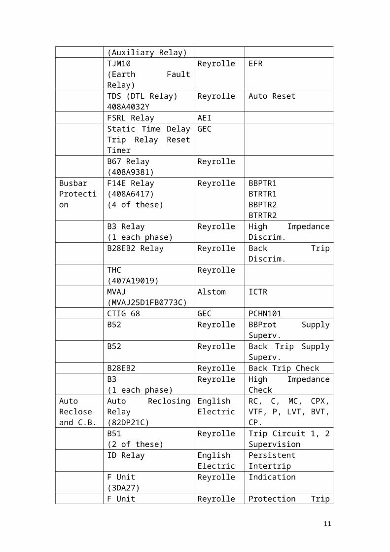
Busbar Protection
F14E Relay(408A6417)(4 of these)
Reyrolle BBPTR1BTRTR1BBPTR2BTRTR2
7

B3 Relay(1 each phase)
Reyrolle High Impedance Discrim.
B28EB2 Relay Reyrolle Back Trip Discrim.THC(407A19019)
Reyrolle
MVAJ(MVAJ25D1FB0773C)
Alstom ICTR
CTIG 68 GEC PCHN101B52 Reyrolle BBProt Supply Superv.B52 Reyrolle Back Trip Supply
Superv.B28EB2 Reyrolle Back Trip CheckB3(1 each phase)
Reyrolle High Impedance Check
Auto Reclose and C.B.
Auto Reclosing Relay(82DP21C)
English Electric
RC, C, MC, CPX, VTF, P, LVT, BVT, CP.
B51(2 of these)
Reyrolle Trip Circuit 1, 2 Supervision
ID Relay English Electric
Persistent Intertrip
F Unit(3DA27)
Reyrolle Indication
F Unit(2DA2)
Reyrolle Protection Trip Repeat
F8E High Speed Relay Reyrolle Auto Reclose SwitchingTDS (DTL Relay)408A4032Y
Reyrolle Line Isolator Sequential Opening
B67(Auto Reclose in service, Auto Reclose out of service, Remote Trip Relay, Remote Close Relay, Isolator Sequential Opening Auxiliary Relay)
Reyrolle 5 relays
B34 (No visible label)B11(Auto Reclose in Progress)
2nd Intertrip Killingholme HSD50 ABBMMLZ(MMLZ21D1AA0751A)
Alstom CTS
MVAX(MVAX12B1CB0756A)
Alstom PSSR
MVAW(MVAW02H1NB0753B)
Alstom IRTR1, IRTR2, IRFR
Creyke Beck HSD50 ABBMMLZ(MMLZ21D1AA0751A)
Alstom CTS
8

MVAX(MVAX12B1CB0756A)
Alstom PSSR
MVAW(MVAW02H1NB0753B)
Alstom IRTR1, IRTR2, IRFR
2nd Main Protection
MCAA(MCAA11B1BC0751C)
Alstom Z220IR
MVTT(MVTT14B1YB0751B)
Alstom VTST
MVAA(MVAA11B1BA0783C)(3 of these)
Alstom DARLPSFRVTSF
MVAA(MVAA11B1AA0783C)
Alstom TRAUX
MVAJ(MVAJ25D1FB0773C)(2 of these)
Alstom TR2TR1
THR Distance Protection ReyrolleMVAJ(MVAJ21D1BA0754A)
Alstom USB
MVAX(MVAX12B1CA075A)
Alstom PSSR
MMLZ(MMLZ03B1AA0001A)
Alstom S10
MVAJ(MVAJ34D1DB0755B)
Alstom PSR
MVAJ(MVAJ34D1DB0753B)
Alstom BMSR
MMLZ(MMLZ02D1AA0751A)
Alstom TTS
MMLZ(MMLZ051B1AA0001A)
Alstom B10
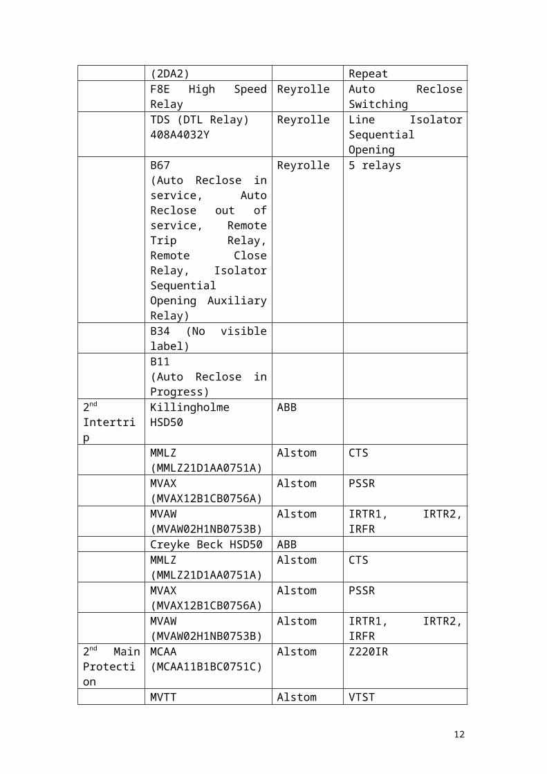
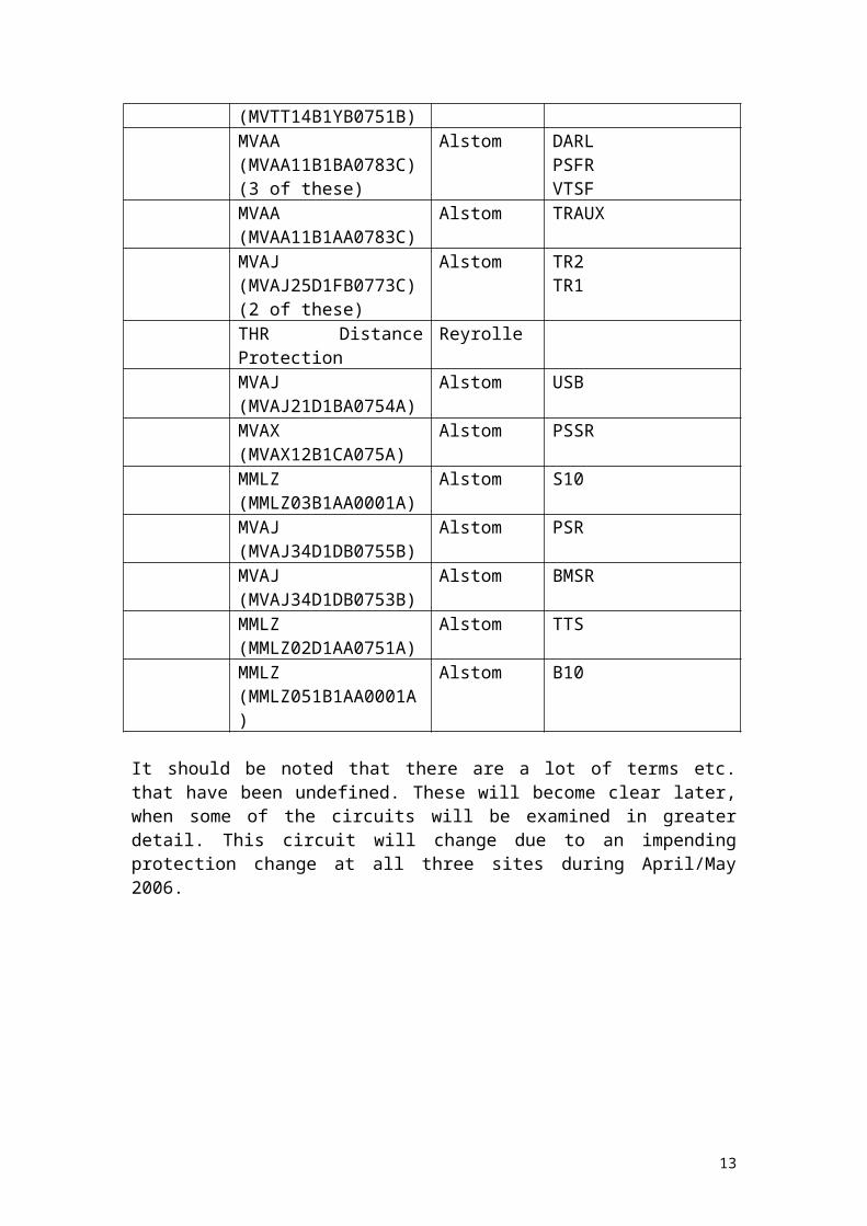
It should be noted that there are a lot of terms etc. that have been undefined. These will become clear later, when some of the circuits will be examined in greater detail. This circuit will change due to an impending protection change at all three sites during April/May 2006.
9

Keadby – West Burton 1 Circuit.
What follows is a list of the protection equipment that is currently installed in the West Burton 1 blockhouse at Keadby 400kV substation:
Rack Name Type Manufacturer NotesWest Burton 1 Feeder
L90Line Differential Relay
GE
MVAX(MVAX31K1CE900A)
Alstom TCS1
MVAX(MVAX31K1CE900A)
Alstom TCS2
MVAW(MVAW11J1AD0611A)
Alstom IPO
MVAW(MVAW11J1AD0611A)
Alstom IPC
MVAA(MVAA11J1AA0783C)
Alstom DIPO
D60Line Distance Relay
GE
MVAJ(MVAJ105JA0802A)
Alstom TS2TR
MVAJ(MVAJ053JA0802A)
Alstom PDTS2TR
C60Breaker Management
GE
MVAA(MVAA21J1AA0751A)
Alstom RB, MB
Busbar Protection
F14E Relay(2 of these)
Reyrolle BBProt TripBBBTRTR
2B3(1 per Phase)
Reyrolle High Impedance Discrim.
B28EB2(2 of these)
Reyrolle BB Back Trip Discrim. And Check
B52(2 of these)
Reyrolle BB Zone Prot. Supply Superv.Back Trip Prot. Supply Superv.
2B3(1 per Phase)
Reyrolle High Impedance Check.
10
Keadby – Spalding North Circuit.
What follows is a list of the protection equipment that is currently installed in the Spalding North blockhouse at Keadby 400kV substation:
Rack Name Type Manufacturer Notes1st Main Protection
B16 Auxiliary Relay Reyrolle Z201R
DDB1 DTL Relay Reyrolle VTSTAR111 Auxiliary Relay Reyrolle VTSFAR111 Auxiliary Relay Reyrolle PSFRTR231 Trip Relay Reyrolle TR1TR231 Trip Relay Reyrolle TR2THRDistance Protection
Reyrolle
TR431Protection In/Out
Reyrolle PSR
B52 Auxiliary Relay Reyrolle PSSRTR512 Trip Relay Reyrolle USB
Spalding North
GRL100Line Differential Prot.
Toshiba
TR431Protection In/Out
Reyrolle PSR
TR231 Trip Relay Reyrolle TR1TR231 Trip Relay Reyrolle TR2AR101 Auxiliary Relay Reyrolle TRAUX
Intertrip XR152Protection Supply Supervision Relay
Reyrolle PSSR
ITM Relay Reyrolle Intertrip test (+key)TR131 Trip Relay Reyrolle IRTRAR111 Auxiliary Relay Reyrolle IRFR
Standby I/T TR131 Trip Relay Reyrolle IRTR1TR131 Trip Relay Reyrolle IRTR2CTS Relay Reyrolle Intertrip test (+key)B52 Auxiliary Relay Reyrolle PSSRAR111 Auxiliary Relay Reyrolle IRFR
Common Protection
F14EO/C + E/F Trip
Reyrolle O/C, E/F
TJM 10 Relay Reyrolle 3 Phase unitFSRLOverload Alarm Relay
AEI
TDSDefinite Time Lag Relay(2 of these)
Reyrolle Auto Reset, Back Trip Auto Reset
B67Trip Relay Remote Reset
Reyrolle
B52O/C + E/F
Reyrolle Protection Supply Supervision
11
Busbar Protection
F14E(2 of these)
Reyrolle BBProt TripBB BTRT
F8E(2 of these)
Reyrolle BBProt BTRT, BBProt. TR
2B3(1 per phase)
Reyrolle High Impedance Discrim.
THB2Breaker Fail Overcurrent Check
Reyrolle
THCBreaker Fail Time
Reyrolle Timers A, B, C, D
B28EB2(2 of these)
Reyrolle Breaker Fail Discrim. And Check
B52(2 of these)
Reyrolle Prot Supply Superv., and Breaker Fail Supply Superv.
2B3(1 per phase)
Reyrolle High Impedance Check
Auto Reclose and CB.
T3DA1Delayed Auto Reclose
Reyrolle
B51(2 of these)
Reyrolle Trip Circuit Superv. 1 + 2
2DA2 Reyrolle Trip Repeat UnitTCD5ID Relay
Reyrolle
HE RelayProtection In/Out
Reyrolle DAR Switch In/Out
3DA27Auto Reclose F Unit
Reyrolle
TCD5Sequential Isol. Open
Reyrolle
B11Auto Reclose in Progress
Reyrolle Repeat Relay
B67(2 of these)
Reyrolle Interposing Open + Close relays
B11Sequential Isol. Auxiliary
Reyrolle
2nd Main Protection
AR101 Auxiliary Relay Reyrolle VHR
DDB DTL Relay Reyrolle VMRTDTR232 Trip Relay Reyrolle TR1TR232 Trip Relay Reyrolle TR2AR101 Auxiliary Relay Reyrolle TRAUXMicromho AlstomTR432Protection In/Out
Reyrolle PSR
B52 Auxiliary Relay Reyrolle PSSRTR512 Trip Relay Reyrolle USB
12
SGT 3.
What follows is a list of the protection equipment that is currently installed in the SGT 3 blockhouse at Keadby 400kV substation:
Rack Name Type Manufacturer NotesTransformer Protection
B3Differential Relay
Reyrolle 1st Circulating Current Protection
MCGG(MCGG62F1CB0753B)
GEC Overcurrent IDMTL
DDB1 DTL Relay Reyrolle 1st Protection Time DelayMVAJ(MVAJ055H1JB0842A)
GEC HV Trip Relay 1
AR101 Auxiliary Relay Reyrolle 1st Protection Auxiliary Relay
FR211 Series Flag Relay GEC Main + Selector Buchholz
B3Differential Relay
Reyrolle 2nd Circulating Current Protection
MCAG(MCAG39F1DA0007A)
GEC High Set O/C Relay
MVAJ(MVAJ055H1JB0842A)
GEC HV Trip Relay 2
AR101 Auxiliary Relay Reyrolle 2nd Protection Auxiliary Relay
FR211 Series Flag Relay GEC Pressure relief + Winding Temperature
HV Connections Protection
B3Differential Relay
Reyrolle 1st Protection System
MVTP(MVTP31F1CB0751D)
GEC CT Supervision Relay
B52 Auxiliary Relay Reyrolle HV Connections 1st
ProtectionMVAJ(MVAJ055H1JB0842A)
GEC HV Connections Protection 1 Trip
B3Differential Relay
Reyrolle 2nd Protection System
B52 Auxiliary Relay Reyrolle HV Connections 2nd
ProtectionMVAJ(MVAJ055H1JB0842A)
GEC HV Connections Protection 2 Trip
Common Services
B51 Supply Supervision Reyrolle TCS1
B51 Supply Supervision Reyrolle TCS2B70 Auxiliary Relay Reyrolle Interpose Open RelayB70 Auxiliary Relay Reyrolle Interpose Close RelayDDB1 DTL Relay Reyrolle Trip Reset Time DelayB52 Auxiliary Relay Reyrolle Trip Relay Reset SS
13

B52 Auxiliary Relay Reyrolle Seq. Isol. SSAR101 Auxiliary Relay Reyrolle Seq. Isol. Aux RelayDDB1 DTL Relay Reyrolle Seq. Isol.DDB1 DTL Relay Reyrolle Seq. Isol. Excessive
Breaker Fail and Busbar Protection
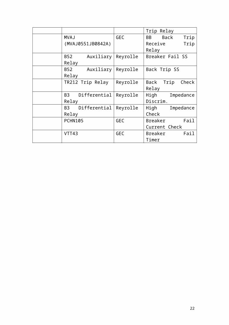
MVAJ(MVAJ0551JB0842A)
GEC BB Prot TR Relay
B52 Auxiliary Relay Reyrolle BB Prot SSTR212 Trip Relay Reyrolle Back Trip Receive Trip
RelayMVAJ(MVAJ0551JB0842A)
GEC BB Back Trip Receive Trip Relay
B52 Auxiliary Relay Reyrolle Breaker Fail SSB52 Auxiliary Relay Reyrolle Back Trip SSTR212 Trip Relay Reyrolle Back Trip Check RelayB3 Differential Relay Reyrolle High Impedance Discrim.B3 Differential Relay Reyrolle High Impedance CheckPCHN105 GEC Breaker Fail Current
CheckVTT43 GEC Breaker Fail Timer
14
Brinsworth – Drax - Keadby Tee.
What follows is a list of the protection equipment that is currently installed in the Brinsworth - Drax blockhouse at Keadby 400kV substation:
Rack Name Type Manufacturer NotesX1003 Line Isolator Magbolt Follower
TR901 Trip Relay Reyrolle PRA
TR901 Trip Relay Reyrolle PRBAR101 Auxiliary Relay Reyrolle MRDDB1 DTL Relay Reyrolle MRTDB73 Auxiliary Relay Reyrolle MRX
Drax 1st
IntertripTR131 Trip Relay Reyrolle IRTR1
TR131 Trip Relay Reyrolle IRTR2CTS Relay Reyrolle Test + KeyB52 Auxiliary Relay Reyrolle PSSRAR111 Auxiliary Relay Reyrolle IRFR
1st Main Carrier Interface
K10 Alstom TKBB101
Brinsworth 1st Intertrip
TR131 Trip Relay Reyrolle IRTR1
TR131 Trip Relay Reyrolle IRTR2CTS Reyrolle Test + KeyB52 Auxiliary Relay Reyrolle PSSRAR111 Auxiliary Relay Reyrolle IRFR
1st Main Protection
B16 Auxiliary Relay Reyrolle Z201R
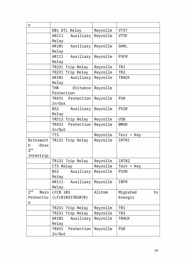
DB1 DTL Relay Reyrolle VTSTAR111 Auxiliary Relay Reyrolle VTSFAR101 Auxiliary Relay Reyrolle DARLAR111 Auxiliary Relay Reyrolle PSFRTR231 Trip Relay Reyrolle TR1TR231 Trip Relay Reyrolle TR2AR101 Auxiliary Relay Reyrolle TRAUXTHR Distance Protection ReyrolleTR431 Protection In/Out Reyrolle PSRB52 Auxiliary Relay Reyrolle PSSRTR512 Trip Relay Reyrolle USBTR431 Protection In/Out Reyrolle BMSRTTS Reyrolle Test + Key
Brinsworth –Drax 2nd
Intertrip
TR131 Trip Relay Reyrolle IRTR1
TR131 Trip Relay Reyrolle IRTR2
15
CTS Relay Reyrolle Test + KeyB52 Auxiliary Relay Reyrolle PSSRAR111 Auxiliary Relay Reyrolle IRFR
2nd Main Protection
LFCB 103(LFCB103S70207B)
Alstom Migrated to Energis
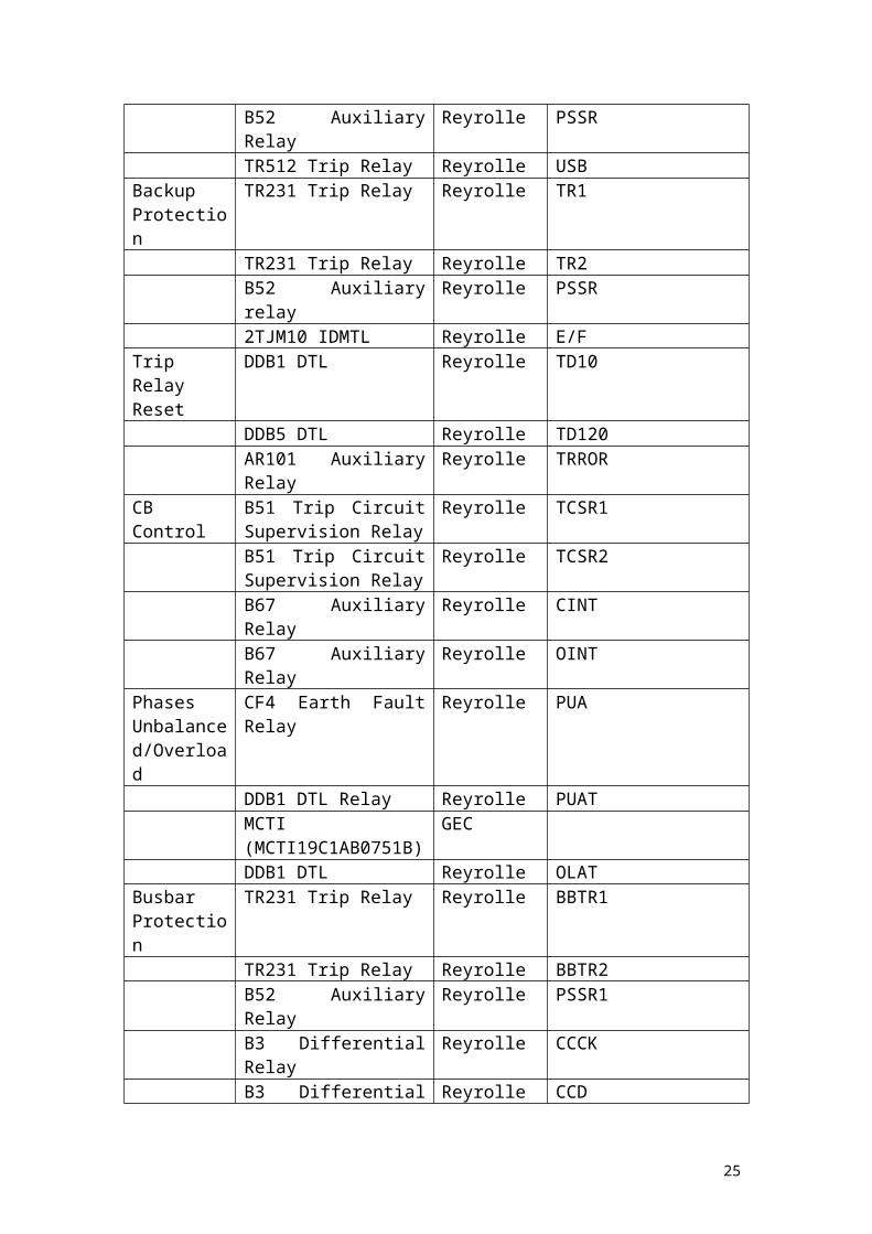
TR231 Trip Relay Reyrolle TR1TR231 Trip Relay Reyrolle TR2AR101 Auxiliary Relay Reyrolle TRAUXTR431 Protection In/Out Reyrolle PSRB52 Auxiliary Relay Reyrolle PSSRTR512 Trip Relay Reyrolle USB
Backup Protection
TR231 Trip Relay Reyrolle TR1
TR231 Trip Relay Reyrolle TR2B52 Auxiliary relay Reyrolle PSSR2TJM10 IDMTL Reyrolle E/F
Trip Relay Reset
DDB1 DTL Reyrolle TD10
DDB5 DTL Reyrolle TD120AR101 Auxiliary Relay Reyrolle TRROR
CB Control B51 Trip Circuit Supervision Relay
Reyrolle TCSR1
B51 Trip Circuit Supervision Relay
Reyrolle TCSR2
B67 Auxiliary Relay Reyrolle CINTB67 Auxiliary Relay Reyrolle OINT
Phases Unbalanced/Overload
CF4 Earth Fault Relay Reyrolle PUA
DDB1 DTL Relay Reyrolle PUATMCTI(MCTI19C1AB0751B)
GEC
DDB1 DTL Reyrolle OLATBusbar Protection
TR231 Trip Relay Reyrolle BBTR1
TR231 Trip Relay Reyrolle BBTR2B52 Auxiliary Relay Reyrolle PSSR1B3 Differential Relay Reyrolle CCCKB3 Differential Relay Reyrolle CCDTR231 Trip Relay Reyrolle BTRTR1TR231 Trip Relay Reyrolle BTRTR2B52 Auxiliary Relay Reyrolle PSSR2TR312 Trip Relay Reyrolle BTDTR312 Trip Relay Reyrolle BTCKTR231 Trip Relay Reyrolle ICTRTR231 Trip Relay Reyrolle ICTRAUX
CB Fail 2DAB Current Check Reyrolle BFCCK12DAB Current Check Reyrolle BFCCK2DDB5 DTL Reyrolle TD1A, TD1B
16

DDB5 DTL Reyrolle TD2A, TD2BB52 Auxiliary Relay Reyrolle PSSR
Delayed Auto Reclose
MVTR(MVTR59F1CD6021D)
GEC DAR
B67 Auxiliary Relay Reyrolle DARIOAR201 Auxiliary Relay Reyrolle DARVMAR101 Auxiliary Relay Reyrolle DARCX
X1003 Sequential Isolator
DDB1 DTL Reyrolle SDTDR
AR101 Auxiliary Relay Reyrolle SDARB52 Auxiliary Relay Reyrolle PSSR
17

SGT 1.
What follows is a list of the protection equipment that is currently installed in the SGT 1 blockhouse at Keadby 400kV substation:
Rack Name Type Manufacturer NotesSupergrid Transformer
F14E Reyrolle HV Protection Trip 1
F14E Reyrolle HV Protection Trip 22B3(1 per phase)
Reyrolle Overall Differential 1
2B3(1 per phase)
Reyrolle Overall Differential 2
B12 Main Buchholz Trip/Winding Temperature Trip
Reyrolle 1 Relay
F14E Reyrolle HV Connections Trip 1F14E Reyrolle HV Connections Trip 2MHJ Relay ReyrolleTJM10 Relay Reyrolle O/CB69 Reyrolle Overcurrent Guard2B3(1 per phase)
Reyrolle HV Connections 1
2B3(1 per phase)
Reyrolle HV Connections 2
TCD5 Reyrolle Stage 2 O/CB52 Reyrolle HV Connections SS 1B52 Reyrolle HV Connections SS 2
CB and Common
B51 Reyrolle Trip Circuit Supervision 1
B51 Reyrolle Trip Circuit Supervision 2
CF2 Reyrolle Phases out of BalanceTDS DTL Reyrolle Line Isol. Seq. OpeningTCD5 Reyrolle Auto ResetEB50(1 per phase)
Reyrolle Sensitive Alarm Relay
TCD5 Reyrolle Sensitive Alarm Time Delay
B11 Reyrolle Isolator seq. Opening Auxiliary
B67 Reyrolle Trip Relays remote resetB67 Reyrolle Interposing OpenB67 Reyrolle Interposing Closed
Busbar Protection
F14E Reyrolle Busbar Protection Trip
F14E Reyrolle Busbar Back Trip Receive Trip
THC Reyrolle 4 Timers
18

B3(1 per phase)
Reyrolle BB High Impedance Discrim.
B52 Reyrolle BB Protection SSB52 Reyrolle Back Trip DC SupplyB52 Reyrolle BB Back Trip CheckB3(1 per phase)
Reyrolle BB High Impedance Check
13kV Tertiary Protection
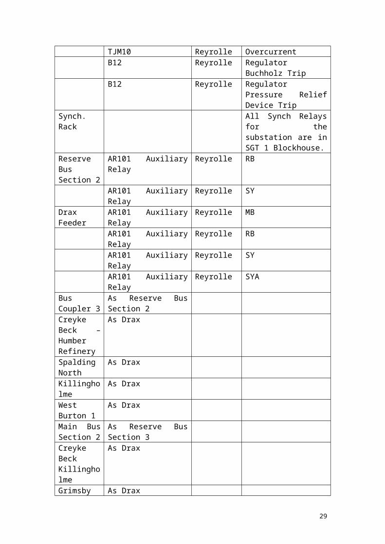
TJM10 IDMT Reyrolle Overcurrent
4B3 Reyrolle 13kV E/FTJM60 Reyrolle Standby E/FB3 Reyrolle 13kV Phase Fault4B3 Reyrolle Restricted Earth FaultB12 Reyrolle Auxiliary Buchholz TripTJM10 Reyrolle OvercurrentB12 Reyrolle Regulator Buchholz TripB12 Reyrolle Regulator Pressure Relief
Device TripSynch. Rack All Synch Relays for the
substation are in SGT 1 Blockhouse.
Reserve Bus Section 2
AR101 Auxiliary Relay Reyrolle RB
AR101 Auxiliary Relay Reyrolle SYDrax Feeder AR101 Auxiliary Relay Reyrolle MB
AR101 Auxiliary Relay Reyrolle RBAR101 Auxiliary Relay Reyrolle SYAR101 Auxiliary Relay Reyrolle SYA
Bus Coupler 3
As Reserve Bus Section 2
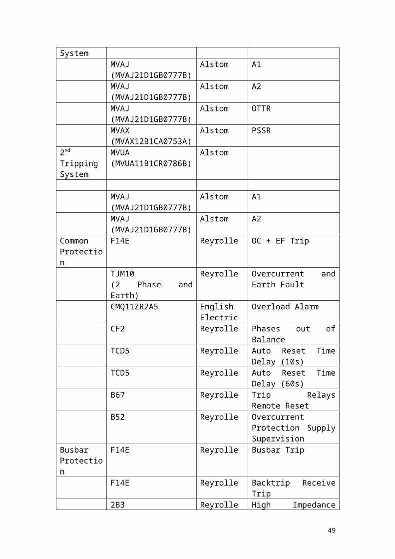
Creyke Beck – Humber Refinery
As Drax
Spalding North
As Drax
Killingholme As DraxWest Burton 1
As Drax
Main Bus Section 2
As Reserve Bus Section 3
Creyke Beck Killingholme
As Drax
Grimsby West
As Drax
Bus Coupler 2
As Reserve Bus Section 3
Cottam 2 As DraxCottam 1 As Drax
19

Bus Coupler 2.
What follows is a list of the protection equipment that is currently installed in the Spalding North blockhouse at Keadby 400kV substation:
Rack Name Type Manufacturer NotesCommission. Protection
B69 Reyrolle Commissioning Instantaneous O/C
TCD4 Reyrolle Timing RelayAncillary Relays
F14E Reyrolle Commissioning O/C Trip
B52 Reyrolle Commissioning O/C SSBusbar Protection
F14E Reyrolle BB Protection Trip
B3(1 per phase)
Reyrolle High Impedance Discrim. Main Bus 2 Coupler
B29 Reyrolle Main 2 Zone Busbar Fault Auxiliary Main 2 Zone
B3(1 per phase)
Reyrolle High Impedance Discrim. Reserve 2
B29 Reyrolle Busbar Fault Auxiliary Reserve 2 Zone
B52 Reyrolle BB Protection SSF14E Reyrolle Busbar Back Trip
Receive TripB3(1 per phase)
Reyrolle High Impedance Check Bus Coupler
THC Reyrolle Timing relay (4 timers)CTIG 68 ReyrolleB28EB2 Reyrolle BB Back Trip Discrim.
Main 2B28EB2 Reyrolle BB Back Trip Discrim.
Reserve 2B28EB2 Reyrolle BB Back Trip Check Bus
CouplerB52 Reyrolle Back Trip Protection SS
Common Protection
F8E Reyrolle O/C + E/F Protection Trip
MCGG(MCGG22D3CB0752A)
GEC
TDS DTL Reyrolle Auto Reset TimingTDS DTL Reyrolle Line Isolator Seq.
OpeningB51 Reyrolle Trip Circuit 1
SupervisionB51 Reyrolle Trip Circuit 2
SupervisionTDS DTL Reyrolle Back Tip Auto Reset
20

B67 Reyrolle Trip Relays Remote ResetB67 Reyrolle Remote Trip RelayB67 Reyrolle Remote Close RelayB11 Reyrolle Isolator Seq. Opening
Auxiliary RelayB52 Reyrolle O/C + E/F Protection SS
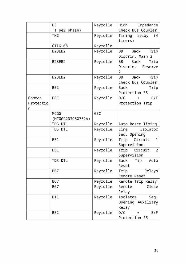
21
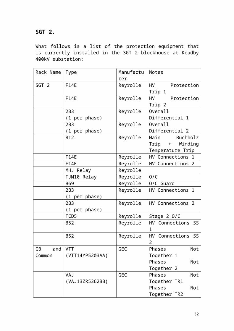
SGT 2.
What follows is a list of the protection equipment that is currently installed in the SGT 2 blockhouse at Keadby 400kV substation:
Rack Name Type Manufacturer NotesSGT 2 F14E Reyrolle HV Protection Trip 1
F14E Reyrolle HV Protection Trip 22B3(1 per phase)
Reyrolle Overall Differential 1
2B3(1 per phase)
Reyrolle Overall Differential 2
B12 Reyrolle Main Buchholz Trip + Winding Temperature Trip
F14E Reyrolle HV Connections 1F14E Reyrolle HV Connections 2MHJ Relay ReyrolleTJM10 Relay Reyrolle O/CB69 Reyrolle O/C Guard2B3(1 per phase)
Reyrolle HV Connections 1
2B3(1 per phase)
Reyrolle HV Connections 2
TCD5 Reyrolle Stage 2 O/CB52 Reyrolle HV Connections SS 1B52 Reyrolle HV Connections SS 2
CB and Common
VTT(VTT14YP5203AA)
GEC Phases Not Together 1Phases Not Together 2
VAJ(VAJ13ZR5362BB)
GEC Phases Not Together TR1Phases Not Together TR2
B51 Reyrolle Trip Circuit 1 Supervision
B51 Reyrolle Trip Circuit 2 Supervision
CF2 Reyrolle Phases out of BalanceTDS DTL Reyrolle Line Isol. Seq. OpeningTCD5 Reyrolle Auto ResetEB50(1 per phase)
Reyrolle Sensitive Alarm Relay
TCD5 Reyrolle Sensitive Alarm Time Delay
B11 Reyrolle Isolator Seq. Opening Auxiliary Relay
B67 Reyrolle Trip Relays Remote ResetB67 Reyrolle Interposing OpenB67 Reyrolle Interposing Close
Busbar F14E Reyrolle Busbar Protection Trip
22

ProtectionF14E Reyrolle Busbar Back Trip
Receive Trip2B3(1 per phase)
Reyrolle High Impedance Discrim.
THB2 Reyrolle Breaker Fail Current Check
THC Reyrolle Timing Relay (4 Timers)B52 Reyrolle BB Protection SSB52 Reyrolle Back Trip DC SupplyB28EB2 Reyrolle BB Back Trip Check +
Discrim.2B3(1 per phase)
Reyrolle High Impedance Check
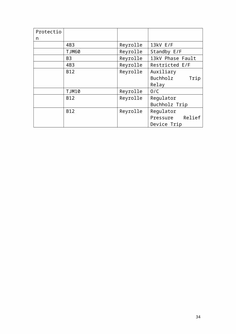
13kV Tertiary Protection
TJM10 IDMT Reyrolle O/C
4B3 Reyrolle 13kV E/FTJM60 Reyrolle Standby E/FB3 Reyrolle 13kV Phase Fault4B3 Reyrolle Restricted E/FB12 Reyrolle Auxiliary Buchholz Trip
RelayTJM10 Reyrolle O/CB12 Reyrolle Regulator Buchholz TripB12 Reyrolle Regulator Pressure Relief
Device Trip
23
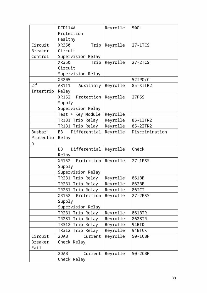
Keadby - Cottam 2 Circuit.
What follows is a list of the protection equipment that is currently installed in the Cottam 2 blockhouse at Keadby 400kV substation. It might also be worth noting that this is one of two circuits at Keadby 400kV substation that contains Quadrature Booster Protection:
Rack Name Type Manufacturer NotesQuadrature Booster ProtectionTripping System 1
FR111 Series Flag Relay Reyrolle 63-SHBUOS
FR111 Series Flag Relay Reyrolle 63-SBUOSFR111 Series Flag Relay Reyrolle 63RTC/BUTSFR111 Series Flag Relay Reyrolle 63YTC/BUTSFR111 Series Flag Relay Reyrolle 63BTC/BUTSFR111 Series Flag Relay Reyrolle 63-RTCDFR111 Series Flag Relay Reyrolle 63-YTCDFR111 Series Flag Relay Reyrolle 63-BTCDDAD3 Circulating Current Relay
Reyrolle 87CC-1/27CTS
DCD114A Protection Healthy
Reyrolle 50N-EF
XR152 Protection Supply Supervision Relay
Reyrolle 27-1PSS
AR101 Auxiliary Relay Reyrolle 86-1XTR231 Trip Relay Reyrolle 86-1ATR231 Trip Relay Reyrolle 86-1BFR111 Series Flag Relay Reyrolle 49-1CTFR111 Series Flag Relay Reyrolle 63-RBUTRFR111 Series Flag Relay Reyrolle 63-YBUTRFR111 Series Flag Relay Reyrolle 63-BBUTR
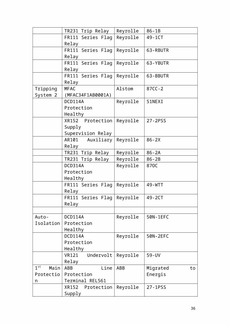
Tripping System 2
MFAC(MFAC34F1AB0001A)
Alstom 87CC-2
DCD114A Protection Healthy
Reyrolle 51NEXI
XR152 Protection Supply Supervision Relay
Reyrolle 27-2PSS
AR101 Auxiliary Relay Reyrolle 86-2XTR231 Trip Relay Reyrolle 86-2ATR231 Trip Relay Reyrolle 86-2BDCD314A Protection Healthy
Reyrolle 87OC
FR111 Series Flag Relay Reyrolle 49-WTTFR111 Series Flag Relay Reyrolle 49-2CT
24
Auto-Isolation
DCD114A Protection Healthy
Reyrolle 50N-1EFC
DCD114A Protection Healthy
Reyrolle 50N-2EFC
VR121 Undervolt Relay Reyrolle 59-UV1st Main Protection
ABB Line Protection Terminal REL561
ABB Migrated to Energis
XR152 Protection Supply Supervision Relay
Reyrolle 27-1PSS
Protection out/in module Reyrolle KeyTR431 Protection out/in Reyrolle 87PSRAR101 Auxiliary Relay Reyrolle 86XTR231 Trip Relay Reyrolle 861TR231 Trip Relay Reyrolle 862
1st Intertrip AR111 Auxiliary Relay Reyrolle 85-XITR1XR152 Protection Supply Supervision Relay
Reyrolle 27-2PSS
Test + Key Module Reyrolle 43-2TR131 Trip Relay Reyrolle 85-1ITR1TR131 Trip Relay Reyrolle 85-2ITR1
2nd Main Protection
THR Distance Protection Reyrolle
XR152 Protection Supply Supervision Relay
Reyrolle 27PSS
Protection Out/In module Reyrolle KeyTR431 Protection Out/In Reyrolle 21-PSRTR512 Trip Relay Reyrolle 21-PUSBlocking Module Reyrolle KeyTest + Key Reyrolle 43-3TR431 Protection Out/In Reyrolle 21-PSBAR101 Auxiliary Relay Reyrolle 86XTR231 Trip Relay Reyrolle 86-1TR231 Trip Relay Reyrolle 86-2AR101 Auxiliary Relay Reyrolle 79LOAR111 Auxiliary Relay Reyrolle 74AR111 Auxiliary Relay Reyrolle 27-VMRDDB1 DTL Relay Reyrolle 2-VMR
Backup Protection
DCD114A Protection Healthy
Reyrolle 51EF
AR101 Auxiliary Relay Reyrolle 86XTR231 Trip Relay Reyrolle 86EF
Trip Relay Reset
DDB1 DTL Relay Reyrolle 2-1TRR
DDB5 DTL Relay Reyrolle 2-2TRR
25

Ferro-resonance switching
XR152 Protection Supply Supervision Relay
Reyrolle 27PSS
XR309 Ferroresonance Detection Relay
Reyrolle 59FRD
DDB5 DTL Relay Reyrolle 2FRDAR101 Auxiliary Relay Reyrolle 57SR1AR101 Auxiliary Relay Reyrolle 57SR2TR231 Trip Relay Reyrolle 57SS1TR231 Trip Relay Reyrolle 27SS2TR212 Trip Relay Reyrolle 94TROXR205 Reyrolle 57IPO/CAR101 Auxiliary Relay Reyrolle 57ESOAR101 Auxiliary Relay Reyrolle 57ESCDDB1 DTL Relay Reyrolle 2ESODDB1 DTL Relay Reyrolle 2ESCDDB7 DTL Relay Reyrolle 2-74ESODDB5 DTL Relay Reyrolle 2-57PNT
Phase unbalanced / overload
DCD124A Protection Healthy
Reyrolle 50PUB
DCD114A Protection Healthy
Reyrolle 50OL
Circuit Breaker Control
XR350 Trip Circuit Supervision Relay
Reyrolle 27-1TCS
XR350 Trip Circuit Supervision Relay
Reyrolle 27-2TCS
XR205 52IPO/C2nd Intertrip AR111 Auxiliary Relay Reyrolle 85-XITR2
XR152 Protection Supply Supervision Relay
Reyrolle 27PSS
Test + Key Module ReyrolleTR131 Trip Relay Reyrolle 85-1ITR2TR131 Trip Relay Reyrolle 85-2ITR2
Busbar Protection
B3 Differential Relay Reyrolle Discrimination
B3 Differential Relay Reyrolle CheckXR152 Protection Supply Supervision Relay
Reyrolle 27-1PSS
TR231 Trip Relay Reyrolle 861BBTR231 Trip Relay Reyrolle 862BBTR231 Trip Relay Reyrolle 86ICTXR152 Protection Supply Supervision Relay
Reyrolle 27-2PSS
TR231 Trip Relay Reyrolle 861BTR
26

TR231 Trip Relay Reyrolle 862BTRTR312 Trip Relay Reyrolle 94BTDTR312 Trip Relay Reyrolle 94BTCK
Circuit Breaker Fail
2DAB Current Check Relay
Reyrolle 50-1CBF
2DAB Current Check Relay
Reyrolle 50-2CBF
XR152 Protection Supply Supervision Relay
Reyrolle 27-3PSS
DDB5 DTL Relay Reyrolle 2-1ACBFDDB5 DTL Relay Reyrolle 2-1BCBFDDB5 DTL Relay Reyrolle 2-2ACBFDDB5 DTL Relay Reyrolle 2-2BCBF
Sequential Isolation
AR101 Auxiliary Relay Reyrolle 89-1X
XR152 Protection Supply Supervision Relay
Reyrolle 27PSS
DDB5 DTL Relay Reyrolle 2-89Delayed Auto-Reset
AR101 Auxiliary Relay Reyrolle 79DARX
XR205 Reyrolle 79I/OB68 Voltage Select Relay
Reyrolle 27LBC
B68 Voltage Select Relay
Reyrolle 27LLC
MVTR(MVTR59F1CD6021F)
Alstom 79DAR
Saltend South OP Tripping1st Tripping System
MVUA(MVUA1B1CR0783B)
Alstom DBI
MVAJ(MVAJ21D1GA0777A)
Alstom A1
MVAJ(MVAJ21D1GA0777A)
Alstom A2
2nd Tripping System
MVUA(MVUA1B1CR0783B)
Alstom DBI
MVAJ(MVAJ21D1GA0777A)
Alstom A1
MVAJ(MVAJ21D1GA0777A)
Alstom A2
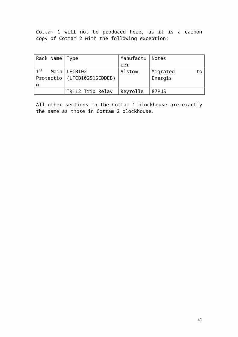
Cottam 1 will not be produced here, as it is a carbon copy of Cottam 2 with the following exception:
27

Rack Name Type Manufacturer Notes1st Main Protection
LFCB102(LFCB102515CDDEB)
Alstom Migrated to Energis
TR112 Trip Relay Reyrolle 87PUS
All other sections in the Cottam 1 blockhouse are exactly the same as those in Cottam 2 blockhouse.
28
Main Bus Section 2.
What follows is a list of the protection equipment that is currently installed in the Main Bus Section 2 blockhouse at Keadby 400kV substation:
Rack Name Type Manufacturer NotesCommon Protection
F14E Reyrolle Overcurrent and Earth Fault Protection Trip
MCGG(MCGG22D3CB0752A)
GEC EF
CMQ11ZR2A5 English Electric
Overload Alarm
CF2 Reyrolle Phases out of balanceTDS DTL Relay Reyrolle Auto Reset Time DelayTCD4 Reyrolle Timing RelayFGL AEI Commissioning
OvercurrentB67 Reyrolle Trip Relay Remote ResetB52 Reyrolle O/C + E/F Protection
Supply SupervisionCircuit Breaker
TDS DTL Relay Reyrolle Isolator Sequential Time Lag
VTT14YP5203AA GEC Static Time DelayVTT14YP5203AB GEC Static Time DelayB51 Reyrolle Trip Circuit no.1
SupervisionB51 Reyrolle Trip Circuit no.2
SupervisionB11EB2 Reyrolle Isolator Sequential
Opening AuxiliaryVAJY13ZR5362BB GEC TrippingVAJY13ZR5362BB GEC TrippingB67 Reyrolle Interposing OpenB67 Reyrolle Interposing Close
Busbar Protection
F14E Reyrolle Busbar Protection Trip
F14E Reyrolle Busbar Back Trip Receive Trip
2B3(1 Per Phase)
Reyrolle High Impedance Discrim. Main Zone 2
2B3(1 Per Phase)
Reyrolle High Impedance Discrim. Main Zone 3
EB2B28 Reyrolle Busbar Back Trip Main 3 Discrim.
EB2B28 Reyrolle Busbar Back Trip Main 2 Discrim.
B29EB2 Reyrolle Main 3 Zone Busbar Fault Auxiliary
29

B29EB2 Reyrolle Main 2 Zone Busbar Fault Auxiliary
B52 Reyrolle Busbar Protection Supply Supervision
B52 Reyrolle Backtripping Protection DC Supply Supervision
2B3(1 Per Phase)
Reyrolle High Impedance Discrim. Check
THB2 ReyrolleTHC Timing Relay Reyrolle 4 TimersEB2B28 Reyrolle Busbar Back Trip Check
Check Zone (Alarm)
E/B50(1 Per Phase)
Reyrolle Check 2
TDS DTL Relay Reyrolle Protection Defective Time Lag Alarm
B24 Reyrolle Protection Defective Time Lag Alarm Repeat
B24 Reyrolle Alarm Supply Supervision
Reserve 2 and 3 Zone (Alarm)
E/B50(1 Per Phase)
Reyrolle Reserve 2 Sensitive Alarm Relay
E/B50(1 Per Phase)
Reyrolle Reserve 3 Sensitive Alarm Relay
B24 Reyrolle Protection Defective Time Lag Alarm Repeat
B24 Reyrolle Protection Defective Time Lag Alarm Repeat Reserve 3
Main 2 and 3 Zone (Alarm)
E/B50(1 Per Phase)
Reyrolle Main 2
E/B50(1 Per Phase)
Reyrolle Main Zone 3
B24 Reyrolle Protection Defective Time Lag Alarm Repeat
B24 Reyrolle Protection Defective Time Lag Alarm Repeat Main 3
Common Busbar Zone
2B3(1 Per Phase)
Reyrolle High Impedance Check
B52 Reyrolle DC Supply Supervision Backtripping Protection
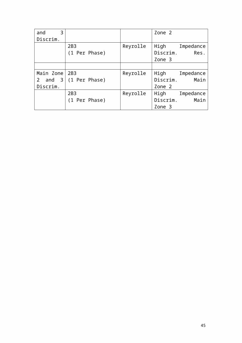
Reserve Zone 2 and 3 Discrim.
2B3(1 Per Phase)
Reyrolle High Impedance Discrim. Res. Zone 2
2B3(1 Per Phase)
Reyrolle High Impedance Discrim. Res. Zone 3
30
Main Zone 2 and 3 Discrim.
2B3(1 Per Phase)
Reyrolle High Impedance Discrim. Main Zone 2
2B3(1 Per Phase)
Reyrolle High Impedance Discrim. Main Zone 3
31
Bus Coupler 3.
What follows is a list of the protection equipment that is currently installed in the Bus Coupler 3 blockhouse at Keadby 400kV substation:
Rack Name Type Manufacturer NotesBackup Protection
B1 Overcurrent Earth Fault Relay
Reyrolle OCR
Protection Select Module Reyrolle KeyTR231 Trip Relay Reyrolle TR1TR231 Trip Relay Reyrolle TR2B52 Auxiliary Relay Reyrolle PSSRTJM10 Earth Fault Relay Reyrolle EFR
Trip Relay Reset
DDB1 DTL Relay Reyrolle TD
AR101 Auxiliary Relay Reyrolle TRRORPhase Unbalanced
CF4 Earth Fault Relay Reyrolle PUA
DDB1 DTL Relay Reyrolle PUATCircuit Breaker Control
B51 Trip Circuit Supervision Relay
Reyrolle TCSR1
B51 Trip Circuit Supervision Relay
Reyrolle TCSR2
B67 Auxiliary Relay Reyrolle CINTB67 Auxiliary Relay Reyrolle OINT
Synch. AR101 Auxiliary Relay Reyrolle RBAR101 Auxiliary Relay Reyrolle SY
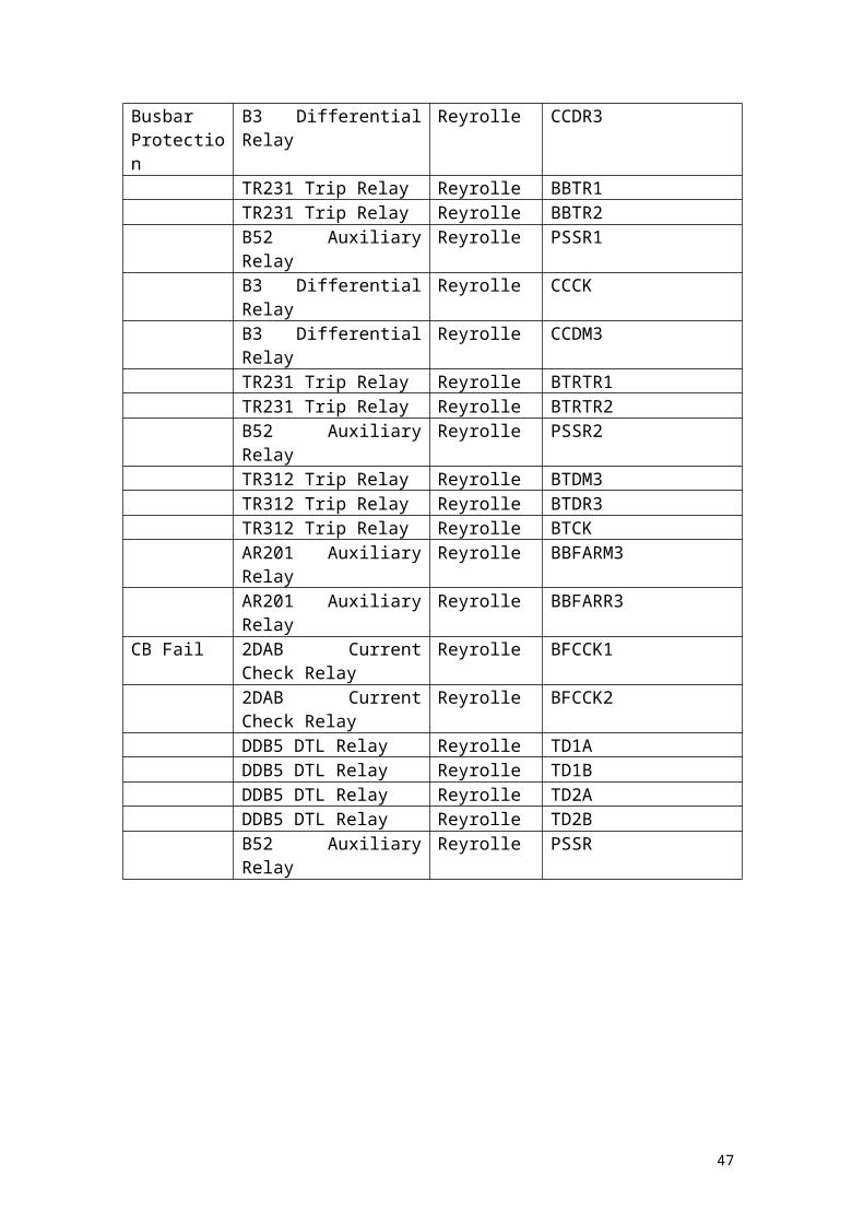
Busbar Protection
B3 Differential Relay Reyrolle CCDR3
TR231 Trip Relay Reyrolle BBTR1TR231 Trip Relay Reyrolle BBTR2B52 Auxiliary Relay Reyrolle PSSR1B3 Differential Relay Reyrolle CCCKB3 Differential Relay Reyrolle CCDM3TR231 Trip Relay Reyrolle BTRTR1TR231 Trip Relay Reyrolle BTRTR2B52 Auxiliary Relay Reyrolle PSSR2TR312 Trip Relay Reyrolle BTDM3TR312 Trip Relay Reyrolle BTDR3TR312 Trip Relay Reyrolle BTCKAR201 Auxiliary Relay Reyrolle BBFARM3AR201 Auxiliary Relay Reyrolle BBFARR3
CB Fail 2DAB Current Check Relay
Reyrolle BFCCK1
2DAB Current Check Relay
Reyrolle BFCCK2
DDB5 DTL Relay Reyrolle TD1A
32

DDB5 DTL Relay Reyrolle TD1BDDB5 DTL Relay Reyrolle TD2ADDB5 DTL Relay Reyrolle TD2BB52 Auxiliary Relay Reyrolle PSSR
33
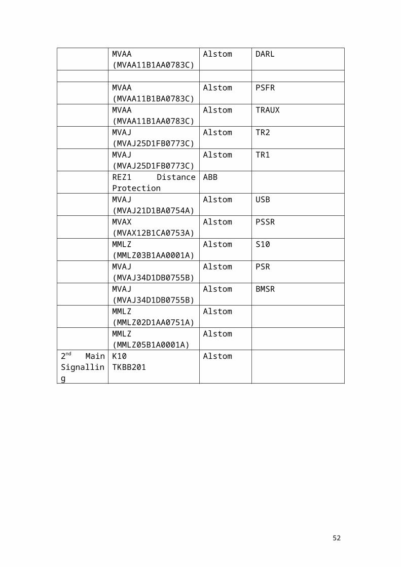
Creyke Beck – Humber Refinery – Keadby Tee.
What follows is a list of the protection equipment that is currently installed in the Creyke Beck – Humber refinery blockhouse at Keadby 400kV substation:
Rack Name Type Manufacturer Notes1st Main Protection
GRL 100 Line Differential Protection
Toshiba
MVAA(MVAA11B1AA0783C)
Alstom TRAUX
MVAJ(MVAJ25D1FB0773C)
Alstom TR2
MVAJ(MVAJ25D1FB0773C)
Alstom TR1
MVAJ(MVAJ21D1BA0754A)
Alstom USB
MVAX(MVAX12B1CA0753A)
Alstom PSSR
MMLZ(MMLZ03B1AA0001A)
Alstom S10
MVAJ(MVAJ34D1DB0755B)
Alstom PSR
1st
IntertrippingMMLZ(MMLZ20D1AA0751A)
Alstom CTS
MVAX(MVAX12B1CA0753A)
Alstom PSSR
MVAW(MVAW02H1NB0753B)
Alstom IRTR1
MVAW(MVAW02H1NB0753B)
Alstom IRTR2
MVAW(MVAW02H1NB0753B)
Alstom IRFR
South Humber Bank OP Tripping1st Tripping System
MVUA(MVUA11B1CR0786B)
Alstom DB1
MVAJ(MVAJ21D1GB0777B)
Alstom A1
MVAJ(MVAJ21D1GB0777B)
Alstom A2
MVAJ(MVAJ21D1GB0777B)
Alstom OTTR
MVAX(MVAX12B1CA0753A)
Alstom PSSR
2nd Tripping System
MVUA(MVUA11B1CR0786B)
Alstom
34

MVAJ(MVAJ21D1GB0777B)
Alstom A1
MVAJ(MVAJ21D1GB0777B)
Alstom A2
Common Protection
F14E Reyrolle OC + EF Trip
TJM10(2 Phase and Earth)
Reyrolle Overcurrent and Earth Fault
CMQ11ZR2A5 English Electric
Overload Alarm
CF2 Reyrolle Phases out of BalanceTCD5 Reyrolle Auto Reset Time Delay
(10s)TCD5 Reyrolle Auto Reset Time Delay
(60s)B67 Reyrolle Trip Relays Remote ResetB52 Reyrolle Overcurrent Protection
Supply SupervisionBusbar Protection
F14E Reyrolle Busbar Trip
F14E Reyrolle Backtrip Receive Trip2B3(1 Per Phase)
Reyrolle High Impedance Discrim.
THB2 ReyrolleTHC Reyrolle Breaker Fail Time DelayB28EB2 Reyrolle Busbar Back Trip
Discrim.B28EB2 Reyrolle Busbar Back Trip CheckB52 Reyrolle Busbar Protection Supply
SupervisionB52 Reyrolle Busbar Back Trip Supply
Supervision MVAJ(MVAJ25D1FB0781C)
Alstom BBPTR2
MVAJ(MVAJ25D1FB0781C)
Alstom BTRTR2
MVAJ(MVAJ25D1FB0773C)
Alstom ICTR
2B3(1 Per Phase)
Reyrolle High Impedance Check
Auto Reclose and Circuit Breaker
T3DA1 Reyrolle Delayed Auto Reclose
VAJY137R5362BB GEC TrippingVAJY137R5362BB GEC TrippingVTT14YP5203AB GEC Static Time DelayVTT14YP5203AB GEC Static Time Delay
VTT11ZR2056C English Persistent Intertrip
35
ElectricB51 Reyrolle Trip Circuit no.1
SupervisionB51 Reyrolle Trip Circuit no.2
Supervision2DA2 Reyrolle Protection Trip Repeat
RelayHE Reyrolle Switching Unit3DA27 Reyrolle Indication F UnitTCD5 Reyrolle Line Isol. Sequential
Time Delay RelayB11 Reyrolle Auto Reclose in Progress
Repeat RelayB67 Reyrolle Interposing OpenB67 Reyrolle Interposing CloseB11EB2 Reyrolle Isolator Sequential
Opening2nd
IntertrippingCreyke Beck MMLZ
(MMLZ07D1AA0751A)Alstom CTS
MVAX(MVAX12B1CA0753A)
Alstom PSSR
MVAW(MVAW02H1NB0753B)
Alstom IRTR1
MVAW(MVAW02H1NB0753B)
Alstom IRTR2
MVAW(MVAW02H1NB0753B)
Alstom IRFR
Humber Refinery
MMLZ(MMLZ07D1AA0751A)
Alstom CTS
MVAX(MVAX12B1CA0753A)
Alstom PSSR
MVAW(MVAW02H1NB0753B)
Alstom IRTR1
MVAW(MVAW02H1NB0753B)
Alstom IRTR2
MVAW(MVAW02H1NB0753B)
Alstom IRFR
2nd Main Protection
MCAA(MCAA11B1BC0751C)
Alstom Z201R
MVTT(MVTT14B1YB0751E)
Alstom VTST
MVAA(MVAA11B1BA0783C)
Alstom VTSF
MVAA(MVAA11B1AA0783C)
Alstom DARL
MVAA Alstom PSFR
36

(MVAA11B1BA0783C)MVAA(MVAA11B1AA0783C)
Alstom TRAUX
MVAJ(MVAJ25D1FB0773C)
Alstom TR2
MVAJ(MVAJ25D1FB0773C)
Alstom TR1
REZ1 Distance Protection
ABB
MVAJ(MVAJ21D1BA0754A)
Alstom USB
MVAX(MVAX12B1CA0753A)
Alstom PSSR
MMLZ(MMLZ03B1AA0001A)
Alstom S10
MVAJ(MVAJ34D1DB0755B)
Alstom PSR
MVAJ(MVAJ34D1DB0755B)
Alstom BMSR
MMLZ(MMLZ02D1AA0751A)
Alstom
MMLZ(MMLZ05B1A0001A)
Alstom
2nd Main Signalling
K10TKBB201
Alstom
37

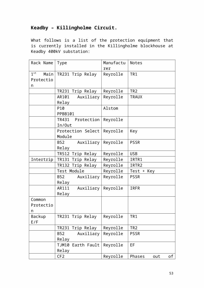
Keadby – Killingholme Circuit.
What follows is a list of the protection equipment that is currently installed in the Killingholme blockhouse at Keadby 400kV substation:
Rack Name Type Manufacturer Notes1st Main Protection
TR231 Trip Relay Reyrolle TR1
TR231 Trip Relay Reyrolle TR2AR101 Auxiliary Relay Reyrolle TRAUXP10PPBB101
Alstom
TR431 Protection In/Out ReyrolleProtection Select Module Reyrolle KeyB52 Auxiliary Relay Reyrolle PSSRTR512 Trip Relay Reyrolle USB
Intertrip TR131 Trip Relay Reyrolle IRTR1TR132 Trip Relay Reyrolle IRTR2Test Module Reyrolle Test + KeyB52 Auxiliary Relay Reyrolle PSSRAR111 Auxiliary Relay Reyrolle IRFR
Common ProtectionBackup E/F TR231 Trip Relay Reyrolle TR1
TR231 Trip Relay Reyrolle TR2B52 Auxiliary Relay Reyrolle PSSRTJM10 Earth Fault Relay Reyrolle EFCF2 Reyrolle Phases out of BalanceTDS DTL Reyrolle Auto Reset Time DelayTDS DTL Reyrolle Auto Reset Time DelayB67 Reyrolle Remote Reset?CMQ11ZR2A5 English
ElectricOverload Alarm
Busbar Protection
F14E Reyrolle Busbar Protection Trip Relay
F14E Reyrolle Busbar Back Trip Receive Trip
2B3(1 Per Phase)
Reyrolle High Impedance Discrim.
THB2 ReyrolleTHC Reyrolle Timing RelayB11 Reyrolle Bus Zone Trip RepeatB11 Reyrolle Back Trip RepeatB28EB2 Reyrolle Busbar Back Trip
Discrim.B28EB2 Reyrolle Busbar Back Trip CheckB52 Reyrolle Busbar Protection Supply
Supervision
38
B52 Reyrolle Back Trip Protection Supply Supervision
2B3(1 Per Phase)
Reyrolle High Impedance Check Relay
Auto Reclose and CB
TD3A1 Reyrolle Auto Reclose G Unit
TDS DTL Reyrolle Isolator Sequential Opening
VTT14YP5203AA GEC Phases Not Together 1VTT14YP5203AA GEC Phases Not Together 2TDS DTL Reyrolle Persistent IntertripB51 Reyrolle Trip Circuit no.1
SupervisionB51 Reyrolle Trip Circuit no.2
Supervision2DA2 Reyrolle Protection Trip Relay
Repeat RelayHE Reyrolle Switching Relay3DA27 Reyrolle Auto Reclose Relay F
UnitVAJ13ZR5362BB Reyrolle Trip Relay 1VAJ13ZR5362BB Reyrolle Trip Relay 2B67 Reyrolle Interposing OpenB67 Reyrolle Interposing CloseB11EB2 Reyrolle Isolator Sequential
Opening AuxiliaryB11 Reyrolle
2nd Main Protection
B16 Auxiliary Relay Reyrolle Z02IR
DDB1 DTL Relay Reyrolle VTSAR111 Auxiliary Relay Reyrolle VTSFAR101 Auxiliary Relay Reyrolle DARLAR111 Auxiliary Relay Reyrolle PSFRTR231 Trip Relay Reyrolle TR1TR231 Trip Relay Reyrolle TR2AR101 Auxiliary Relay Reyrolle TRAUXTHR Distance Protection ReyrolleTR431 Reyrolle PSRProtection In/Out Module
Reyrolle Key
B52 Auxiliary Relay Reyrolle PSSRTR512 Trip Relay Reyrolle USB
South Humber Bank OP TrippingTripping System 1
MVUA(MVUA11B1CR0785B)
Alstom DB1
39

MVAJ(MVAJ21D1GB0777B)
Alstom A1
MVAJ(MVAJ21D1GB0777B)
Alstom A2
MVAJ(MVAJ21D1GB0777B)
Alstom OTRR
MVAX(MVAX12B1CA0753A)
Alstom PSSR
Tripping System 2
MVUA(MVUA11B1CR0785B)
Alstom DB1
MVAJ(MVAJ21D1GB0777B)
Alstom A1
MVAJ(MVAJ21D1GB0777B)
Alstom A2
40
Reserve Bus Section 2.
What follows is a list of the protection equipment that is currently installed in the Reserve Bus Section 2 blockhouse at Keadby 400kV substation:
Rack Name Type Manufacturer NotesMain Protection
DCD414A Protection Healthy
Reyrolle 51/51N
TR231 Trip Relay Reyrolle 86-1AR101 Auxiliary Relay Reyrolle 86-XProtection In/Out Module
Reyrolle
Phases Unbalanced
DCD124A Protection Healthy
Reyrolle 50PUB
CB Control XR350 Trip Circuit Supervision Relay
Reyrolle 27-1TCS
XR350 Trip Circuit Supervision Relay
Reyrolle 27-2TCS
XR205 Reyrolle 52OCTrip Relay Reset
DDB1 DTL Relay Reyrolle 2TRR
AR101 Auxiliary Relay Reyrolle 86-TRRCB Fail 2DAB Current Check
RelayReyrolle 50-1CBF
2DAB Current Check Relay
Reyrolle 50-2CBF
Busbar Zone B3 Differential Relay Reyrolle 87-1BB Zone 2, Zone 3B3 Differential Relay Reyrolle 87-CHBBTR231 Trip Relay Reyrolle 86-1BBXR152 Protection Supply Supervision Relay
Reyrolle 27-2PSS
TR231 Trip Relay Reyrolle 86-1BTRXR152 Protection Supply Supervision Relay
Reyrolle 27-3PSS
TR312 Trip Relay Reyrolle 94-BTD1 Zone 2TR312 Trip Relay Reyrolle 94-BTD2 Zone 3TR312 Trip Relay Reyrolle 94-BTCHAR201 Auxiliary Relay Reyrolle 87X1/2
41

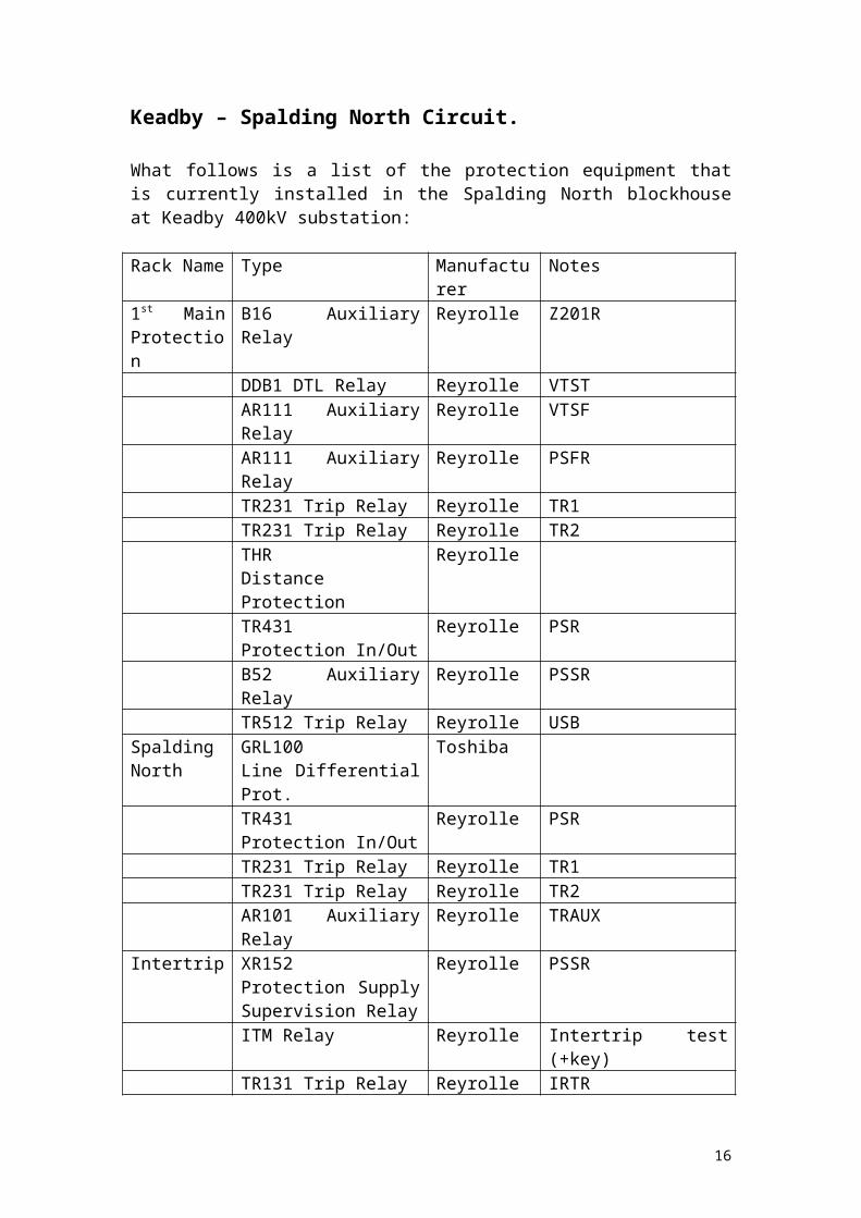
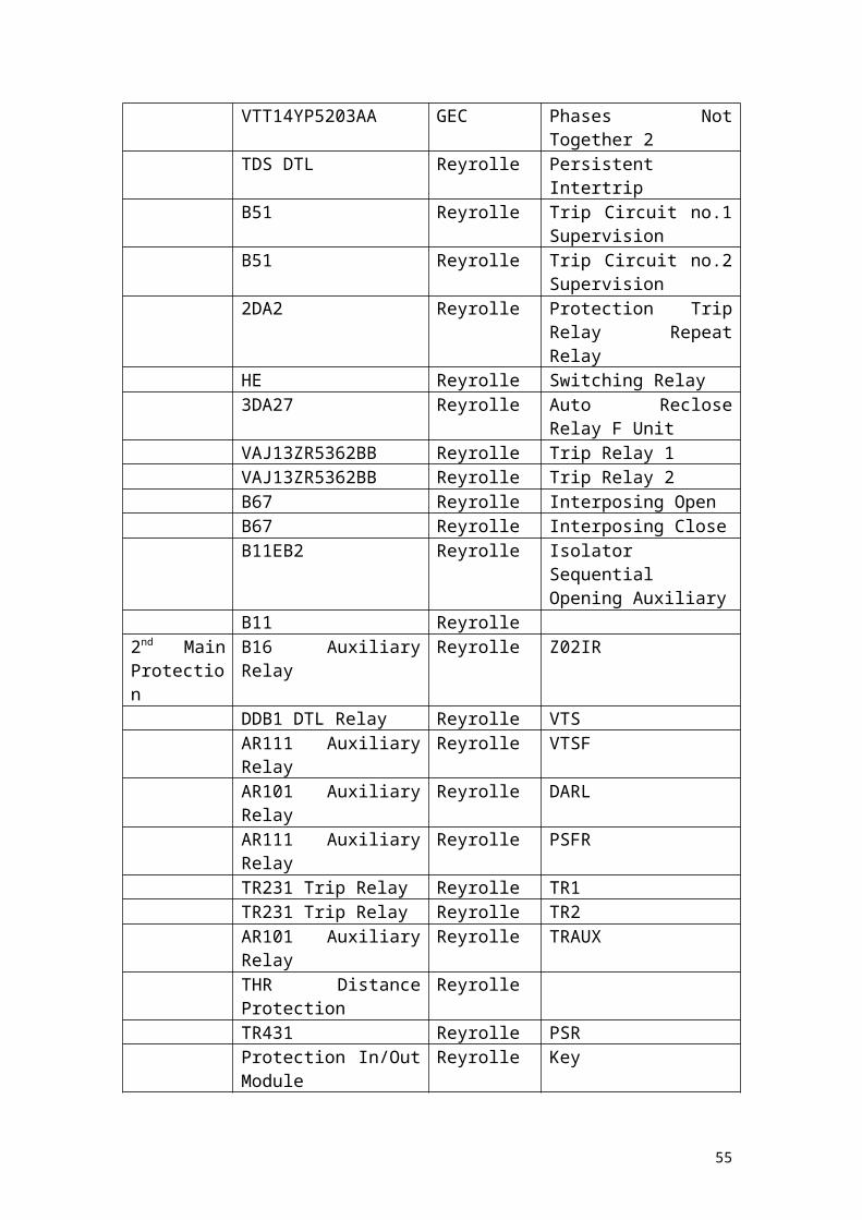
Keadby – Grimsby West Circuit.
What follows is a list of the protection equipment that is currently installed in the Reserve Bus Section 2 blockhouse at Keadby 400kV substation:
Rack Name Type Manufacturer Notes1st Main Protection
TR231 Trip Relay Reyrolle TR1
TR231 Trip Relay Reyrolle TR2AR101 Auxiliary Relay Reyrolle TRAUXP10PPBB101
Alstom
TR431 Reyrolle PSRProtection Selection Module
Reyrolle Key
B52 Auxiliary Relay Reyrolle PSSRTR512 Trip Relay Reyrolle USB
1st Intertrip TR131 Trip Relay Reyrolle IRTR1TR131 Trip Relay Reyrolle IRTR2Test Module Reyrolle Test + KeyB52 Auxiliary Relay Reyrolle PSSRAR111 Auxiliary Relay Reyrolle IRFR
Backup EF TR231 Trip Relay Reyrolle TR1TR231 Trip Relay Reyrolle TR2B52 Auxiliary Relay Reyrolle PSSRTJM10 Earth Fault Relay Reyrolle EFRTDS DTL Relay Reyrolle Auto ResetF14E Reyrolle Overcurrent and VT
Buchholz tripFSRL AEI Pickup RelayB67 Reyrolle Remote Reset?B52 Reyrolle O/C + E/F Protection
Supply SupervisionF8S Reyrolle VT Buchholz Repeat
RelayVTT14YP5218AA GEC Static Time Delay
Busbar Protection
F14E Reyrolle Busbar Protection Trip Relay 1
F14E Reyrolle Back Trip Receive Trip Relay 1
F14E Reyrolle Busbar Protection Trip Relay 2
F14E Reyrolle Back Trip Receive Trip Relay 2
B3(1 Per Phase)
Reyrolle High Impedance Discrim.
B28EB2 Reyrolle Busbar Back Trip Discrim.
42

2DAB Current Check Relay
Reyrolle BFCCK1
2DAB Current Check Relay
Reyrolle BFCCK2
B52 Reyrolle Busbar Protection Supply Supervision
B52 Reyrolle Back Trip Protection DC Supply Supervision
B28 Reyrolle Busbar Back Trip CheckB3(1 Per Phase)
Reyrolle High Impedance Check
Auto Reclose and CB
VAR82DP21C English Electric
RC, C, MC, CPX, VTF, P, LVT, BVT, CP
B51 Reyrolle Trip Circuit no.1 Supervision
B51 Reyrolle Trip Circuit no.2 Supervision
TDS DTL Relay Reyrolle Persistent Intertrip3DA27 Reyrolle Indication F Unit2DA2 Reyrolle Protection Trip RepeatF8E Reyrolle Auto Reclose SwitchingTDS DTL Relay Reyrolle Line Isolator Sequential
OpeningB67 Reyrolle Auto Reclose in ServiceB67 Reyrolle Auto Reclose out of
ServiceB67 Reyrolle Remote Trip RelayB67 Reyrolle Remote Close RelayB11 Reyrolle Isolator Sequential
Opening AUXRB34 Reyrolle ?B11 Reyrolle Auto Reclose in Progress
2nd Intertrip TR131 Trip Relay Reyrolle IRTR1TR131 Trip Relay Reyrolle IRTR2Test Module Reyrolle Test + KeyB52 Auxiliary Relay Reyrolle PSSRAR111 Auxiliary Relay Reyrolle IRFR
2nd Main Protection
AR101 Auxiliary Relay Reyrolle VMR
DDB1 DTL Relay Reyrolle VMRTDTR231 Trip Relay Reyrolle TR1TR231 Trip Relay Reyrolle TR2AR101 Auxiliary Relay Reyrolle TRAUXMicromhoSHNB 102
GEC
TR431 Reyrolle PSRProtection Selection Module
Reyrolle Key
B52 Auxiliary Relay Reyrolle PSSR
43

TR512 Trip Relay Reyrolle USBSouth Humber Bank OP TrippingTripping System 1
MVUA(MVUA11B1CR0785B)
Alstom DB1
MVAJ(MVAJ21D1GB0777B)
Alstom A1
MVAJ(MVAJ21D1GB0777B)
Alstom A2
MVAJ(MVAJ21D1GB0777B)
Alstom OTRR
MVAX(MVAX12B1CA0753A)
Alstom PSSR
Tripping System 2
MVUA(MVUA11B1CR0785B)
Alstom DB1
MVAJ(MVAJ21D1GB0777B)
Alstom A1
MVAJ(MVAJ21D1GB0777B)
Alstom A2
44
Circuit Selection.
Unfortunately it is not feasible, nor within the bounds of the project to examine all the circuits at Keadby 400kV Substation, and thus only a sample will be taken to be examined in depth.
The following circuits (with reasons) will be examined more thoroughly:
Keadby – Grimsby West since the project also examines Grimsby West 400kV Substation, tying them together seems logical.
Keadby – Cottam 2 since there is a Quadrature Booster on that circuit.
Finally, Keadby – Creyke Beck – Killingholme Circuit as it is a Teed Circuit. This one has been chosen over the other teed circuits as there is to be a change in the protection coming up and there will be an opportunity to add to the project by examining a brand new system.
Each circuit chosen will be examined separately.
45

Keadby – Cottam 2 Circuit.
As previously mentioned, this circuit is one of two circuits going to/coming from Cottam. Both circuits contain a Quadrature Booster and both are relatively new units.
From the list (starting on page 24) it is noted that the 1st and 2nd Main Protections are REL561 and THR Distance respectively. We will begin with an overview of the Main Protections and then move on to the remaining protection systems associated with this circuit.
REL561
REL561 is a Line Differential Protection, manufactured by ABB and can be used in many ways, but the principal use and, indeed, the only way used in this case is as a Current Differential Protection (evidenced on the drawing as showing only CT inputs) which takes measurements of current and angle and outputs according to the values measured. It is a form of Unit Protection.
The other modes are as Fuse Failure Supervision, Power Swing Detection, Earth-Fault Overcurrent Protection, Auto Reclosing, Synchronism and Energising Check, Breaker Failure Protection, Fault Locator and Event/Disturbance Recorder. None of these are used in this case, and thus will not be dealt with in any detail.
Dealing with the primary use of REL561, the Currents measured are filtered and the pure-wave components (sine and cosine) extracted using a Fourier method. Therefore there are a total of six components, given the three phase currents and these are sent as a message to the remote end every 5ms (delays due to signal propagation are automatically dealt with). In the event of loss of communication, REL561 could act as purely distance protection, but since that function is not used, the protection will simply go dead (naturally there would be an alarm, but there is nothing that would trip anything) and the system would therefore have to rely on the second main protection.
In addition to this, the basic function of REL561 also covers Supervision, CT Saturation and so on. The settings sheet for this circuit can be found in Appendix C, along with the circuit diagrams for the protection.
In summary, therefore, we have a Current Differential Protection, with constant communications with the other end. In the next section we will see how this works
Current Differential Protection and REL561
For Current Differential schemes, a carrier channel is used to send both Amplitude and Angle to the remote end for comparison. Transmission of the signal may be done either by Voice Frequency with FM Modulation or by Analogue to Digital Converters and using Digital transmission. Signal delays due to propagation are dealt with by introducing deliberate delays in the local signal before comparison. Any delays are dealt with automatically as each signal is time tagged.
46
A Trip operation is determined not only by a measured difference in the quantities, but also if the guard relays also operate where the guard relays detect step changes in operation (such as an overcurrent condition). A differential operation is simply an operation where it has been found that the quantities compared differ beyond a certain tolerance (the value of which will be found on the settings sheet).
With the REL561 unit, the premise is much the same, but the Fourier method explained previously is used as the comparison basis. Without delving into the theory too much, the Fourier Method is a transformation method working along the theory that any wave can be mathematically constructed from the fundamental waves (the classic Sine and Cosine waves) and addition of the various harmonics of the fundamental waves. When the wave is transformed using this method, peaks are seen that correspond to the fundamentals at the appropriate frequency (or wavelength) and also at the corresponding harmonics present in a given wave (the height of these peaks give us the weighting of that particular component in the overall wave). Upon transformation, the fundamental waves can be represented by Fourier Coefficients (say, a and b) which REL561 stores and uses these for comparison (with a time tag). Such a method almost eliminates any harmonic influences, as their coefficients calculated using a Fourier Transformation are more or less ignored. Given the speed of each evaluation of the constants a and b, (approximately 1ms for 5 such calculations) it is suggested that the actual transformation is not necessarily a full Fourier transformation but a Fast Fourier Transformation (same theory, but calculation is less onerous and thus quicker, but is an approximation as opposed to a definite value).
For evaluation of the components, two quantities are derived – the Differential Current and Bias Current, the former being the vector sum of the coefficients a and b and the latter being the scalar sum of a and b divided by 2. These values are compared with the stabilisation characteristic of REL561 and operation can be determined from this. The diagram on the next page shows this characteristic and the key to the diagram:
47

Where the graph is below the normal operation line, there should be no operation and where the situation arises where it is above that same line, operation should occur. CT saturation (where the Secondary winding effectively acts as a short circuit) is to be avoided if the protection is to operate correctly.
The key above also relates to the same quantities in the settings sheet.
We can relate the operation of the protection to the Circuit Diagrams:
The CTs are connected such that the star point points towards the remote end (that is, the star point is pointing towards Cottam) – a well established method and are brought into the relay room to terminal blocks (TB-X4875, TB-X4876 and TB-X4877 on drawing 872.02/106/sheet 1) and from there go into the scheme (drawing 872.02/106/sheet 4).
The CTs input into REL561 through wires A11, A31, A51 (the phases) and A70 (the neutral). These inputs feed into the protection and there the input is analysed by REL561. Given an event where a trip operation is required and the protection is switched in, the TRIP-GTRIP switch will close, putting 110V through K33A, through contacts 6 and 8 of 87PSR (since this will be closed if the protection is switched in on
48
the Protection Switching Relay at the top of 872.02/106/sheet 4) and energising the Trip Relays (86-1 and 86-2) along with the Auxiliary Trip Relay (86-X).Trip Relay 1 (86-1) will close between contacts 5 and 7 and send a signal to CB. Trip Coil 1 which will go through to trip the circuit breaker (X705, on 872.02/106/sheet 13). The switches between contacts 6 and 8 and 9 and 11 will close, enabling the first intertrip to operate through 43-2 to the OPTO ISOL on DIFF-TRTRIN which will lead to the send. In turn, the remote end will receive the intertrip and send a signal back to be received by REL561, closing the DIFF-TRTROUT switches, allowing operation of the Intertrip relays (85-1ITR1, 85-2ITR1 and 85-XITR1), closing contacts and allowing other schemes to begin such as CB Fail, Trip Relay Reset, Ferroresonance, Sequential Isolation, Delayed Auto Reclose and the Fault Recorder. The second intertrip works in a similar fashion to the first except that it is initiated from Trip Relay 86-2 and uses a different communication channel.
Acting alongside the actual protection we have the alarms, which are set off to indicate what has happened depending on which relays have operated. 872.02/106/sheet 20 shows all the connections for the alarms which can be picked up by the Substation Control System.
For communications which are required in order for some of the protection schemes to work (notably intertripping), the REL561 uses digital communication systems, in use constantly as it transmits data to the remote end every 5ms (each message is 22 bytes long). Under normal circumstances, losses due to attenuation limit the distance to approximately 32km maximum.
The settings for REL561 are explained below:
Name Value NotesDIFF PROTECTION SETTING ON This one is fairly obvious.CT Factor (CS) 1 This factor matches the primary currents
in the CTs with the remote end.Imin SAT 500% Minimum value of current for which
Saturation Detection will occur.Imin OP 20% Minimum value of current for which the
protection will operate.Idiff LV/1 40% Stabilisation Characteristic (see Graph).Idiff LV/2 60% Stabilisation Characteristic
(See Graph).ILV 1/2 Cross 500% The point of intersection of the two
stabilisation characteristics (see Graph).Trip Evaluate 3 of 4 For Tripping, 3 out of 4 messages must be
accepted.Trip Logic Operation 3ph Only 3 phase tripping.HSOC Off High Set Overcurrent detection is off –
this removes the necessity of the guard relays and allows tripping to be done without it first being enabled.
TM2 Diff. Comm Fail 5s Time to determine communication failure.TM1 System Reset 3s Time for reset after operation.
49

THR Distance Protection.
The Second Main Protection system on the Keadby – Cottam 2 circuit is THR Distance Protection. In this particular case both ends are set on blocking – meaning that the remote end is blocked from tripping the remote end circuit breaker in the event of an operation under certain circumstances – particularly important if the protection is looking backwards as well as forwards and picks up a fault behind it as there would be no need for the other end to trip.
Distance Protection works on the premise of impedance measurement and uses the value obtained to determine where the fault is (since the magnitude of the impedance will differ with respect to the fault – the higher the impedance the further away the fault is) and also to determine if operation is necessary. Thus both Voltage Transformers and Current Transformers are required in order for the protection to calculate the impedance. Furthermore, the detection is broken down into zones, which have a certain reach dependent upon the settings made and operation required (see settings sheet).
The impedance in question for the purposes of this protection is the impedance in the line that it is protecting (on the diagrams this is represented by the line, having a characteristic angle due to the nature of the line itself), meaning that the further away the protection looks, the higher the impedance will be. The measured impedance is compared with the impedance expected and if the measured value is less than that expected, it is assumed that there is a fault present in that section, and operation commences. Under normal conditions (i.e.: No faults) the measurements would indicate a point well outside the Zone 3 region (more towards R than X), and therefore the system will run smoothly without action. Sometimes the normal running conditions would impinge on Zone 3, and the characteristic of Zone 3 can be changed to give it a more lenticular shape thereby reducing the likelihood of a mal-operation.
Typically, distance protection operates over three zones in a consecutive manner (although this is most certainly not the only way to do this) such as that shown below:
50
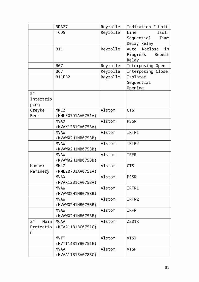
Diagram taken from Chapter 11, Network Protection and Automation Guide, Areva T&D, 2005.
The second diagram shows how blocking would work in such a scheme, which will be examined in greater detail later. Although the first diagram shows busbar zone protection, considering the origin of the diagram as a substation and the lines across the solid straight line from the origin as second and third remote substations respectively expands the idea.
Basically speaking, when faults are detected in zone 1, the operation is immediate and a signal is sent to the remote end (substation 2) and a trip occurs, effectively removing the fault from the system. If a fault is detected in zone 2, there is a time delay of approximately 0.5s before trip is initiated and if the fault is detected in zone 3, a delay of 1s is applied before tripping. The delays are to ensure that, in the event of one or more distance protection systems failing to pick the fault up, there will be a trip somewhere in order to remove the fault from the system. Ideally, however, zone 1 will pick up the faults and the trip will be immediate (to within the standard tolerances for fault clearance, typically 80ms from detection to operation of the circuit breaker).
It should be pointed out at this point, that the zones between the different substations overlap a great deal. For example zone 1 at substation 1 sees approximately 80% down the line and zone 1 at substation 2 also sees 80% down the line – thus there is an overlap of zone 1 from each substation for the central 60% of the line. This means that different operations will occur dependent on where the fault lies and may also affect any signalling to the remote end.
51
Zone two typically covers 150% of the line – that is, the whole line and looks 50% beyond substation 2. Zone three would typically cover up to 50% beyond substation 3. These characteristics can be exploited to provide a high level of protection and fault clearance given various circumstances. This also means that there could be a fault, say, Ratcliffe on Soar, Grendon or Eaton Soccon and zone 3 would detect this, but would only have a chance to trip under exceptional circumstances.
Another key feature of distance protection is that the detection equipment can be set to look backwards – that is to look behind the protection to detect faults. This can be useful in that substation 1 could see a fault behind it and thus signal substation 2 and tell the protection there (which would in theory see it as a zone 2 fault) NOT to trip as it can see the fault and will trip itself. A signal could then theoretically be sent backwards (to substation 0) and tell that to trip if it hadn't already done so. It could be said that the protection at substation 1 blocks substation 2 from tripping. Furthermore, it should also be mentioned that under no circumstances should distance protection be looking through a transformer and the settings should reflect this. It is important; however, that distance protection should not examine circuits beyond transformers, making the setting of Zone 3 in particular a not so trivial task.
This is more or less the way that the THR Distance protection is used on the Keadby-Cottam 2 circuit.
By it’s definition; THR (manufactured by Reyrolle) is not a unit protection.
From drawing 872.02/106/sheet 5, it can be demonstrated how the protection works if called upon to operate. Note that it will operate in conjunction with the first main protection (REL561), thus the trip coils will receive multiple signals due to each main protection operating, and the intertrip signals received (or not received in the case of blocking). Generally speaking, however, the trip relays that send the signals to the trip coils are fitted with ‘cut-throat’ contacts so that if the trip relay operates, it will not keep operating after the initial trip signal is received.
As before, the CT is arranged in such a manner that the star point is looking down the line towards Cottam. The inputs come from A311 (red phase), A331 (yellow phase), A351 (blue phase) and A370 (neutral – star point). These go in to TB-X4875, TB-X4876 and TB-X4877 respectively. All three on the star side also go in to the same terminal blocks respectively and the neutral (A370) comes out from that.
However, in this case, differing from the first main protection is the input from the VT, as this protection requires both Voltage and Current, in order to calculate the impedance. In this case it comes from a Line CVT where each phase (E320, red; E340, yellow; E360, blue and E380, neutral) enter the relay room at TB-X4874 and from there go into the protection. The protection will process the readings and comparison to the settings internally and in the event of a trip, TR1-1 (or TR2-1) will close, allowing 110V to flow into the Trip Relays (86-1, 86-2 and 86-X) to begin the tripping sequences. In this case, 86-1 will close between contacts 5 and 7, allowing a signal to be sent to Trip Coil 2 and contacts 6 and 8 and 9 and 11 will also close, allowing for an intertrip signal to be sent in the same manner as for the REL561 protection.
52
Blocking with THR Distance Protection.
The premise is quite simple. The THR Distance Protection set up at Keadby 400kV substation is such that there are four zones for the protection to cover – the first three are as convention – an immediate tripping zone covering the first 80% of the line, a delayed second zone (approximately 0.5s) which covers up to 150% (that is, the whole line and up to 50% towards substation 3.) and a delayed third zone (approximately 1s) which covers the line, the second line up to substation 3 and beyond.
The fourth zone is different in that it looks behind the protection (the other three zones can be said to be looking forward) – and could be set up similar to zone 1 in that it can cover up to 80% of the line behind it (the distance this zone sees is not too important except for the fact that it must overlap the first zone on the preceding substation, and look beyond zone two from the remote substation) and set for an immediate trip (the exact set up will be explained when the settings are dealt with), which can communicate to the other end it is looking at (behind) and tell that end to trip via communications in order to clear the fault. However, dependent on where the fault is behind the protection, zone 2 or zone 3 from substation 2 (which is in front) or zone 3 from substation 3 (which is also in front) could pick this fault up as they can see the fault and trip when it is not really required as the fault can be cleared at substation 1. In order to prevent substation 2 or 3 from tripping, a signal can be sent from the protection at substation 1 via a communication method that can tell the protection at substations 2 and 3 that the fault is behind it and it will clear the fault and there is no need to trip. In essence, the protection at substations 2 and 3 are blocked from tripping. For tripping to occur in a given zone, it is important to realise that the fault will appear inside the characteristic zone shape (be it circular or lenticular or otherwise).
The communications work in a similar way to intertripping, except the signal is to communicate a non-operation as opposed to an operation. It should be noted that both intertripping and blocking are used on this circuit for operations.
It is clear, therefore, that how this works is vital to understanding how the whole distance protection scheme for this circuit works. The settings for this THR unit follow:
53

Relay Function Relay Type Setting NotesSecond Main THR (BLK) Zone 1: A = 6.4
G = 0.7 E = x1
Settings for Zone 1
Zone 2: H = 1.9 S = x1
Settings for Zone 2
Zone 3: K = 6.3 M = x1 N = 0.1 P = Fwd R = 35ms
Settings for Zone 3
Used in blocking.Zone 4: C = 3.8 Settings for Zone 4
(looking backwards).
J = 0.5sL = 1.0sD = 750
Characteristics for time delay (Zone 2, Zone 3) and Angle.
HSOC = 400% Not used.B = 6.4F = 0.4
Residual Compensation settings.
Zone 1 = 4.48 sec ohmsZone 2 = 8.512 sec ohmsZone 3 = 28.224 sec ohms
Zone reaches (secondary Ohms).
Other Schemes.
There are other protection schemes associated with the circuit – which are related to the main protection, but not necessarily completely associated with them. For example, the auto reclose scheme would act after the main protection has opened the circuit breaker, or the circuit breaker fail scheme would only act if the main protection had actually tried to open the circuit breaker and failed to do so. There is also another scheme which can act with the main protection, or act on its own accord if necessary – the Ferroresonance scheme.
Ferroresonance Scheme.
Ferroresonance is a complex phenomenon that has been long known about but not well understood. It is characterised by a sudden onset of very high voltages with high levels of harmonics and can be damaging to equipment.
It is similar to normal resonance in that it occurs when the inductive and capacitive reactances of a circuit balance. In a series circuit it leads to a minimum impedance and in a parallel circuit it leads to a maximum impedance. The only mitigating factor is the presence of any pure resistance as this remains the same, regardless of frequency.
However, Ferroresonance is further distinguished by the following:
54
1. There exists several stable responses to changes in parameters.2. The response is dependent upon initial conditions.3. Resonance at a given frequency can occur over a wide range of
parameter values.4. The resonant frequency can be different for each stable response.
Ferroresonance occurs due to the fact that the inductance in the circuit is ferromagnetic – that is the core is made up of a ferromagnetic material (often Iron). A good example of this is the supergrid transformers, which have iron in their cores regardless of how they may be made (laminated or otherwise).
With a ferromagnetic core, the flux density in a coil will increase and therefore so will the magnetic induction – this can be much larger than the induction associated with the current in the coil itself. Furthermore, ferromagnetic materials can saturate and they can also exhibit hysteresis behaviour.
An iron core coil can be tested by applying a current and measuring the magnetic flux density. When this is done, a curve is generated and it can be seen that, as the current increases, the magnetic flux density also increases – but not linearly. There is a slow rise in magnetic flux density as current increases, which increases and becomes linear for a while before tailing off again – meaning that beyond a certain point, an increase in current will no longer increase the magnetic flux density. This results in saturation of the iron core.
This diagram shows how magnetic flux varies with current – a basic hysteresis loop. Taken from Network Protection and Automation Guide, Areva T&D, 2005.
By looking to Quantum theory we can see why this occurs. It can be said that the structure of Iron is crystalline – that is if we take a piece of iron and look at it under a microscope it could be seen that the Iron is made up of crystals all joined together in a haphazard fashion. In fact it is this structure that gives iron its strength since each crystal will be in a random direction there is no way to find an axis that is necessarily weaker than another. Indeed, the basic structure of metals in general follows this idea.
Each crystal structure will contain protons, neutrons and electrons, as expected. Some of the electrons will be bound to the crystalline structure, but some will be free to roam (this is a property of metals and is the principle reason why they are good conductors – some have more free electrons than others and thus are better conductors). Each electron, be it free or otherwise, will have certain properties due to
55

its position within the structure (the term position is used loosely here, as it is more concerned with energy levels than physical position).
Basic quantum theory assigns electrons ‘positions’ (the term is used loosely as it is not a physical position per se) based upon energy and angular momentum (or spin) – the idea of an atom where the electrons orbit the nucleus is no longer a valid assumption to make (although it is a useful visual aid) and the electrons obey sets of rules, which will not be examined here. More complex theories suggest other rules in that no two electrons can occupy the same state (Fermi-Dirac Statistics). It is in particular the spin that we are interested in, or more specifically, the magnetic spin (also known as the magnetic quantum number ml). In absence of any external influences we can take a step back and examine the crystalline structures as a whole relative to each other. The overall effect of the magnetic spin for one domain will assign it a random direction (within the framework of the rules) and the sum of all the directions will lead to zero overall, meaning no overall magnetisation of the material.
If we apply a magnetic field (via a current, which has a magnetic field associated with it – for a wire it is symmetrical and is around the wire in a cylindrical shape, direction given by the ‘right hand set’ rule) to this material the effect is quite startling. The individual electrons within each crystal will align with the other electrons in surrounding crystals, giving a net magnetisation – in other words the material will become magnetic. Of course, the amount of magnetisation will depend on the number of like-aligned electrons and this is dependent on the size and orientation of the magnetic field being applied.
There reaches a point where all of the electrons magnetic spin characteristics line up. At this point we have saturation of the material – and no further magnetisation can take place, regardless of any increase of the magnetic field.
Since there is a need for a magnetic field to align the electrons, simply removing the current will not change the magnetisation of the material much (it will decrease, but not return to zero). In order to reduce the magnetisation of the material to zero, a reverse magnetic field (that is, a reversal of the magnetising current) is required.
The gradient of the curve on the previous page is related to the inductance of the coil. It can therefore be seen that as we go above the saturation point, the inductance changes dramatically. This leads to the conclusion that the resonance frequency (where the capacitive and inductive reactances balance) will vary due to the fact that the inductance can vary dependent on the saturation of the coil. Thus a wide range of capacitive and inductive reactances can lead to resonance. This will lead to extremely high values of voltage and current present at a wide range of frequencies, of which the range can possibly be predicted, but the exact frequency when this occurs very difficult to predict. The damage is not difficult to predict however – in the event of ferroresonance occurring and not being dealt with, damage to plant (particularly transformers) is spectacular.
Fortunately, ferroresonance can be taken care of by design:
56

1. Use a delta connected primary VT (not necessarily practical)2. Prevent the system from becoming ungrounded (not necessarily
possible)3. Purchase a VT designed to operate a much lower induction values so
that the saturation point is at least twice the system voltage (in case of National Grid this would be both expensive and not necessarily possible, especially at 400kV.)
4. Introduce losses by means of load resistances (this is probably the easiest and cheapest solution but in the event of load resistance varying, this will not be a perfect solution)
The result of this is that for this system (Keadby – Cottam 2 circuit), ferroresonance may occur and thus there is a protection system designed to operate earth switches if it is detected (or if the conditions leading up to ferroresonance are detected).
The Ferroresonance protection comes from the VT (in this case CVT) on the Keadby – Cottam 2 circuit (Red, Yellow and Blue phases into TB-X4874). Upon detection of Ferroresonance (from the input of the phases and detection by 59FRD), the Ferroresonance Time Delay Relay 2FRD will drop, closing the switch between contacts 2 and 4, allowing the Earth Switch to be closed. The opening of the Earth Switch is controlled by time delay relays (57SR1, 57SR2 leading to 57SS1 and 57SS2) which will open the Earth Switch if the conditions are right (see 872.02/106/sheet 9).
Upon operation of the Ferroresonance protection, the Circuit Breaker and disconnector (X705 and X704 respectively) will have been opened, which are also conditions that must be satisfied before the Earth Switch (X701A) can close. Alarms will go off to the control system (L8370 from contacts 9 and 11 on the 2FRD relay) – the Ferroresonance detected alarm.
Of course, upon a normal operation requiring a trip of the circuit breaker, the Ferroresonance detection relay is called upon automatically (contacts 14 and 16 on 86-1 on 872.02/106/sheet 5 or sheet 4) and if ferroresonance is detected, will start the Earth Switch Closing as described above (the disconnector and the circuit breaker are already receiving signals from elsewhere). Technical Specification NGTS 3.24.80 shows how a Ferroresonance scheme works in detail. Note that Ferroresonance protection will not trip a circuit.
The settings for this scheme are as follows:
Relay Function Relay Type Setting NotesFerroresonance Detector Timer
DDB5 M1 = 200s, M2 = 0.010; t = M1 x M2 = 2sPCB Dil Switch = T.L. Oper
Will operate after a time lag of 2s.
Ferroresonance Earth Switch Closing Timer
DDB1 M1 = 400s, M2 = 0.010; t = M1 x M2 = 4sPCB Dil Switch = T.L. Oper
Will operate after a time lag of 4s.
Ferroresonance Earth Switch Opening Timer
DDB1 M1 = 400s, M2 = 0.010; t = M1 x M2 = 4sPCB Dil Switch = T.L. Oper
Will operate after a time lag of 4s.
57
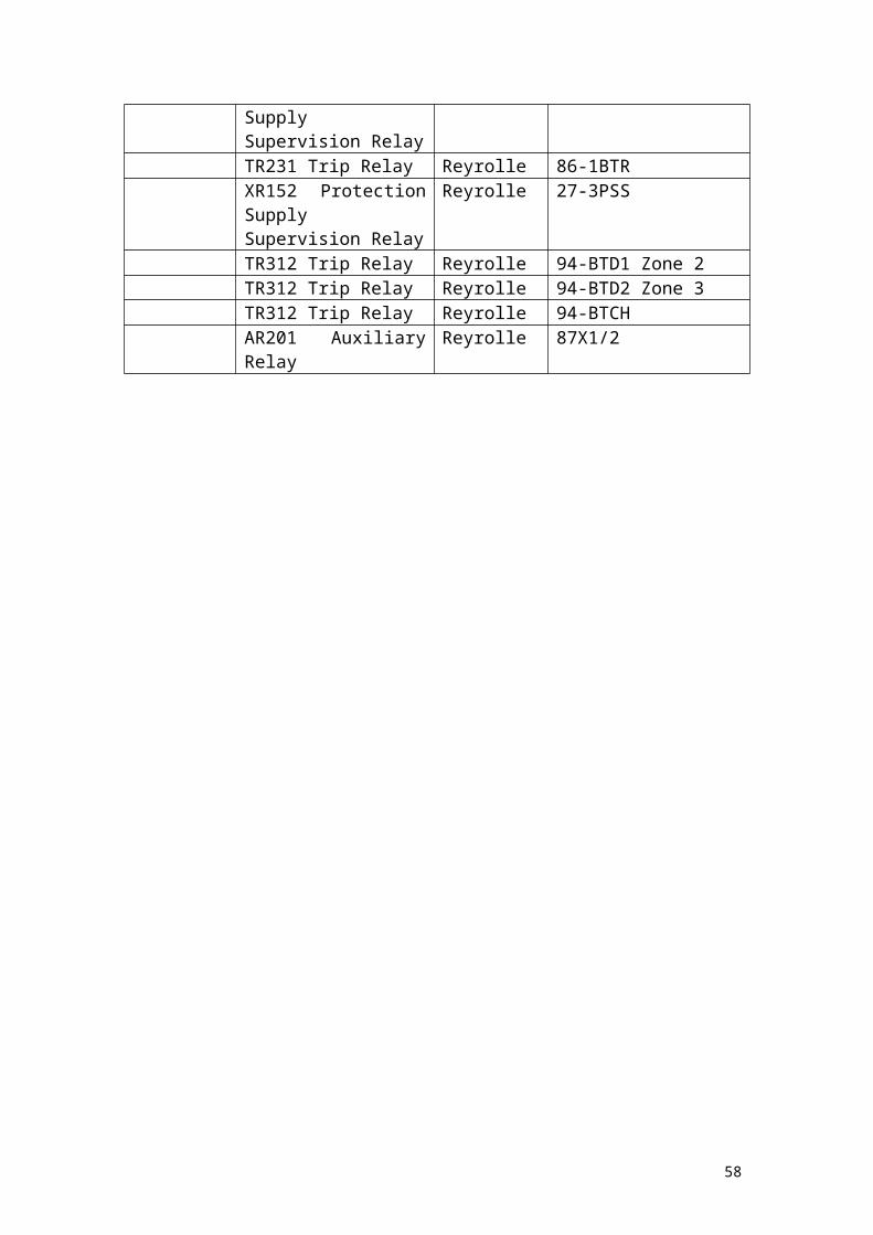
Auto Reclosing Scheme.
The Auto-Reclosing scheme relies on the fact that the Circuit Breaker and the disconnector have opened to clear a fault and are due to reclose onto either a fault (triggering another operation of the circuit breaker and disconnector, repeat until the auto reclose feature has locked out) or onto a healthy line and normal operations ensue.
An interesting feature of this scheme is that it works closely with the circuit breaker fail scheme and can lock out the protection scheme if the circuit breaker has failed (to prevent the protection calling upon a faulty circuit breaker to open and possibly causing catastrophic damage). Assuming a healthy protection system that has tripped out on a fault, the delayed auto reclose scheme will start and 79DAR will activate. There is a check first to determine synchronisation that will allow 79DARX to operate and will close the circuit breaker by sending a close signal to the circuit breaker disconnectors.
In the event of a circuit breaker failing, the close lockout relay will close and, with the other switches closed on that circuit, the protection lockout is brought in, and the circuit breaker scheme will look for an alternative. Technical Specification NGTS 3.24.16 shows how the DAR scheme should work in detail.
The settings for this scheme are shown below:
Relay Function Relay Type Settings NotesDAR MVTR59 Timers: Dead Time = 5s
Close Pulse = 2s Reclaim Timer = 2s ID Timer = 60sSoftware Functions: Function 3 and Function 8 DLC or Sync Check, all others nothing.Function 8 set to 1 – RL3 Operates for A/R in service
Circuit Breaker Fail Scheme (and Earth Fault Check Scheme).
This scheme comes in when a trip signal is sent to the breaker, but due to a fault with the equipment, the circuit breaker fails to operate.
The CT concerned with this scheme is also part of the Earth Fault Check scheme so both schemes will be described here. The star point looks down the line towards Cottam (as expected) and all 3 phases and the neutral connect into the protection through TB-X4880, TB-X4881 and TB-X4882.
This one is relatively simple to interpret. From 872.02/106/sheet 8, the inputs from the CTs go into 50-1CBF and 50-2CBF relays. Upon detection of a circuit breaker fail,
58
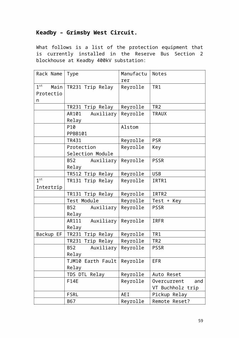
the switches from 50-1CBF and 50-2CBF close (contacts 1 and 2 and 3 and 4 respectively on both relays) and 2-1ACBF and 2-1BCBF operate to put a supply onto the back trip buswires (872.02/106/sheet 7) which will allow the discriminating and check relays to detect the fault and act accordingly to open alternative circuit breakers (from the ops diagram, this could be all the way back to X260 or X220 if necessary, with all the implications involved for other circuits attached (although NOC could auto switch the circuits across to the other busbar if required). Either way a circuit breaker failure would take out a significant portion of the substation and should be avoided if at all possible.
The Circuit Breaker fail scheme is also linked with the auto-isolation scheme and the backup protection scheme (not a protection unit like THR, or REL561, but rather a series of relays put together to form a scheme in the event that the two main schemes fail to pick up on various faults) through the Earth Fault Check system.
The Earth Fault Check system uses 50N-1EFC and 50N-2EFC to check for Earth Faults and upon detection of one will operate P.U. Delay switches which go to the Disconnector control system for disconnectors X742, X743A and X743B on 872.02/106/sheet 19 which will open these disconnectors. Note that by this time, the circuit breaker should be open as all of this is on a time delay. Technical Specification NGTS 3.24.39 shows how the Breaker Fail scheme should work in detail.
The settings for this scheme are below:
Relay Function Relay Type Setting NotesBreaker Fail Current Check 1
2DAB Is = In x >% = 20% (400A, 277MVA)I > Is: Pole A = 20A, Pole B = 20A, Pole C = 20A.
If current is greater than 20% of the pole currents then operate.
Breaker Fail Current Check 2
2DAB As above As above
Breaker Fail Timer 1A
DDB5 M1 = 130s, M2 = 0.0010; t = M1 x M2 = 0.130s
Operate after 0.130s
Breaker Fail Timer 1B
DDB5 As above As above
Breaker Fail Timer 2A
DDB5 As above As above
Breaker Fail Timer 2B
DDB5 As above As above
HV Differential Overcurrent Protection Scheme.
This scheme uses two CTs – either side of the Quadrature Booster in a form of unit protection. The inputs from the CTs (red, yellow, blue phases and neutral) go into the scheme via terminal blocks TB-X4880, TB-X4881 and TB-X4882 for the busbar side and TB-X4875, TB-X4876 and TB-X4877 for the line side. Since we are looking at two CTs looking over a piece of equipment this is considered to be a unit scheme.
59
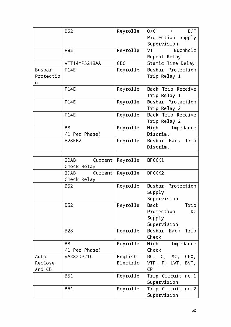
From 872.02/106/sheet 3 the inputs from the CTs enter the HV 3PH DIFF.OC PROT relay (87 OC) and can initiate a trip if the IDMT (Inverse Definite Minimum Time) switch is closed (contacts 11 and 12) as well as the INST (Instantaneous) switch is closed (contacts 21 and 22). The signal goes to 86-1, 86-2 and 86-X which sends the trip signal to the circuit breaker.
It should be mentioned what is meant by Inverse Definite Minimum Time at this point. With differential relays the time it takes for them to operate is proportional to the amount of current detected. The greater the current, the shorter the time taken for an operation:
Characteristics of Inverse Relays taken from Network Protection and Automation Guide 2005.
The equations relating the different characteristics to the curves are as follows:
60
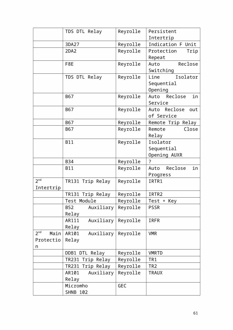
Equations relating to the Inverse Time Curves taken from Chapter 15, Network Automation and Protection Guide, 2005.
Where there is a minimum time there is an override of the curve – if there is a minimum time of 1s for example, then no matter how high the current, even if the curve would theoretically drop below 1s for operation, the relay will only operate after 1s.
The settings for this scheme are shown below:
Relay Function Relay Type Setting NotesQB Differential O/C
DCD314A Power System Frequency = 50HzPH Rating = 1APole Type (B Pole) = P/FE/F Mode Select = SEF
Obvious
P/F Characteristic Setting = 0.6P/F Characteristic TM = 0.15P/F Lowset Setting = 1.00P/F Highset 1 Setting = 0.7P/F Highset 2 Setting = 10.00P/F Characteristic Delay = 5.00Relay Reset Delay = INST
Current Setting
Time Multiplier
Current SettingCurrent SettingTime Delay
Reset TimeWaveform Pre Trigger = 10%Summary:Current Setting (1) = 0.6ACharacteristic = NITime Multiplier = 0.15TMCurrent Setting (2) = 0.7ACharacteristic = N/AOperating Time = INST
Current SettingNormal InverseTime MultiplierCurrent SettingNo CharacteristicInstantaneous
61

Backup Protection Scheme.
The Backup Protection Scheme takes its inputs from the Fault Recorder/Differential CTs that have their star point facing towards Cottam and the inputs (red, yellow, blue and neutral) come in through TB-X4875, TB-X4876 and TBX4877. The signal is processed through 51EF and this will put a supply on to 86EF which will send signals to the trip coils, disconnectors, Ferroresonance Scheme and the Trip Relay Reset Scheme. Given that the backup protection is for Earth Fault only and will not cover phase to phase faults, it is assumed that in the event that the two main protections fail the time taken for the failure to be detected any fault would have generated into an earth fault and thus the backup protection will see it. There does not appear to be any communication with the remote end in this scheme.
The settings for the Backup Scheme are as follows:
Relay Function Relay Type Settings NotesBU E/F DCD114A Power System Frequency =
50Hz
E/F rating = 1APole Type = E/FE/F CT Ratio = 2000:1Characteristic Delay = 5sSummary: Current Setting 0.5ACharacteristic = NITime Multiplier = 0.3TM
Self Explanatory
1A Relay
Obvious
Setting for operationNormal InverseThis relay will operate if the current detected is above 0.5A and the delay is 1.5s.
Phases Unbalanced and Overload Scheme.
As with the Backup protection, this scheme uses the Fault Recorder CTs for the inputs. There appears to be no tripping associated with this scheme, but when called upon for operation, alarms will be generated and sent to the Substation Control System.
The settings for the two relays concerned are shown below:
62

Relay Function Type Settings NotesO/L Alarm DCD114A Power System Frequency =
50HzObvious
E/F Rating = 1A 1A RelayE/F CT Ratio = 2000:1Pole Type = E/FE/F Characteristic Setting = 1.55E/F Characteristic Delay = 3sE/F Characteristic TM = 1.00E/F Characteristic = DTL This relay will
operate if the current detected is 1.55A after a 3s delay to generate an alarm.
Busbar Protection Scheme.
This is the last scheme before the Quadrature Booster is examined in detail. The Busbar Protection will be described in full as pertaining to Keadby 400kV Substation since there is only one system for the whole site.Busbar protection at Keadby 400kV Substation uses the Merz-Price principle of current differential where the CT and interconnections form an analogue of the Busbars and Feeders of the substation called Buswires. Relays across the Buswires would represent a fault in the larger system and therefore would only become energised when a fault occurs. This is shown in principle in the diagram below:
Diagram to show basic principle of Busbar Protection. Taken from Network Protection and Automation Guide.
In order to provide the maximum possible protection for the Busbars, ‘zones’ are used that overlap so that all areas are covered and this is shown in principle below:
63
Diagram to show the Busbar Protection ‘Zones’. Taken from Network Protection and Automation Guide.
At Keadby, which is a double busbar substation, the Main and Reserve Bars are treated as having separate zones, overlapping at the Bus Coupler circuit. Since Feeders can be on either busbar at any given time, auxiliary contacts are used on a ‘early make, late break’ principle that will change the shape of the zones as needed, but still ensuring that the overlaps are made correctly for that particular configuration of the substation.
Positioning of the CTs is therefore crucial to the correct operation of the protection, since there is a chance of a ‘short zone’ fault where the busbar protection operates, but the fault will still be fed from the feeder. This undesirable situation will occur if the CTs are Feeder side (or Line side) of the Circuit Breaker. In the event that the CTs are either side of the Circuit Breaker, then there will be no short zone and therefore no chance for a short zone fault to occur – the diagram below illustrates this in practice:
64
Diagram showing the possible positions of the CTs and how this could cause problems for Busbar Protection. Taken from Network Protection and Automation Guide.
Note that the diagram above shows the ideal position of the CTs to avoid short zones but this does not mean that this does not occur in substations. Where there are short zones for whatever reason, additional protection is required to prevent non-clearance of short zone faults.
In essence, the key to busbar protection is location and clearance of the correct section of busbar and this is done by using a ‘2 out of 2’ principle with busbar check and busbar discrimination relays. Given a busbar fault, all of the check relays within the substation will operate, but the discrimination relays will only operate if the fault is within the bus-zone that they are covering and when both relays operate within a given bus-zone, the relevant circuit breakers can operate to clear the fault. In extreme cases (and this has never occurred in memory) a distance protection that is set to look backwards could operate after their time delay and remove circuits feeding into the fault, but this would cause more problems than solve and could lead to the substation becoming ‘islanded’ from the system at large – a very undesirable situation.
The settings for both check and discriminating relays are fixed at 33mA.
Quadrature Booster Protection.
Although the scheme in general would work quite well on its own, the introduction of Quadrature Boosters to the circuit means that there must be a protection scheme to deal with any problems both mechanical and electrical that may occur with these
65

units. This is done in two stages – the overall Quadrature Booster Protection and the Quadrature Booster LV Earth Fault Protection.
Quadrature Booster Overall Protection.
It may be helpful at this point to define what a Quadrature Booster is and the purpose of it. A Quadrature Booster (which is also known as a Phase-Shifting Transformer) controls the flow of real power. It does this by taking the supply, shifting it by 900 and then reapplying the result to the original. The effect of this is to reduce the amount of real power going down the overhead lines therefore in essence allowing the system to apply more real power than would normally be allowed due to thermal ratings.
A Quadrature Booster consists of two units – a shunt unit where the phase shift takes place and a series unit where the phase shifted component is added. There is a tap system that can be used to control the magnitude of the quadrature component to increase this component or to decrease it as needed. The overall voltage is simply the vector sum of the real and quadrature voltages. The following diagram (courtesy of Wikipedia) shows how a Quadrature Booster is set up:
66

Schematic Diagram of Quadrature Booster Set up. Retrieved from "http://en.wikipedia.org/wiki/Quadrature_booster"
The protections associated with the Quadrature Booster are generally unit protection schemes, or are mechanical in nature. In essence the Quadrature Booster is a type of transformer (or maybe more exactly, two transformers) and for the most part, is treated exactly as such.
The Quadrature Booster has dedicated CTs for the protection system and the connections are made in TB-X4880, TB-X4881 and TB-X4882 for each phase and the neutral (from the star points of all three CTs) and TB-X4875, TB-X4876 and TB-X4877 for the second CT phases. The third CT inputs into TB-X4945 and all the CTs are connected to each other for the input into the protection relays 87CC-1 and 27CTS (872.02/106/Sheet 2). This overall protection scheme would appear to be a circulating current scheme where each CT has a common neutral, which is earthed, and the phases monitor the current. Each CT has the same ratio (in this case 2000:1) and essentially the premise is that the current will circulate and balance – in essence there is a differential system. The presence of a tap changer will also cause no problems since there are high impedance relays within the circuit. Where the current is not balanced this will lead to a current flow in the secondary of the CTs that is also not balanced and thus there will be current flowing in the relay, starting the protection response. Spill currents (where current flows in the relay even though the system is balanced) are unavoidable in any scheme, and are taken into account in the settings of the relay.
In the event there is a call for an overall trip, the relay 87CC will detect this and close a switch between contacts 1 and 3, putting a supply to the trip relays 86-1A, 86-1B and 86-1X.
All of the other protection systems associated with the Quadrature Booster will also send signals to the trip relays, such as oil surges on each phase and so on (all indicated on 872.02/106/sheet 2 and CSB3246/sheet 4), but these signals will only result in a
67
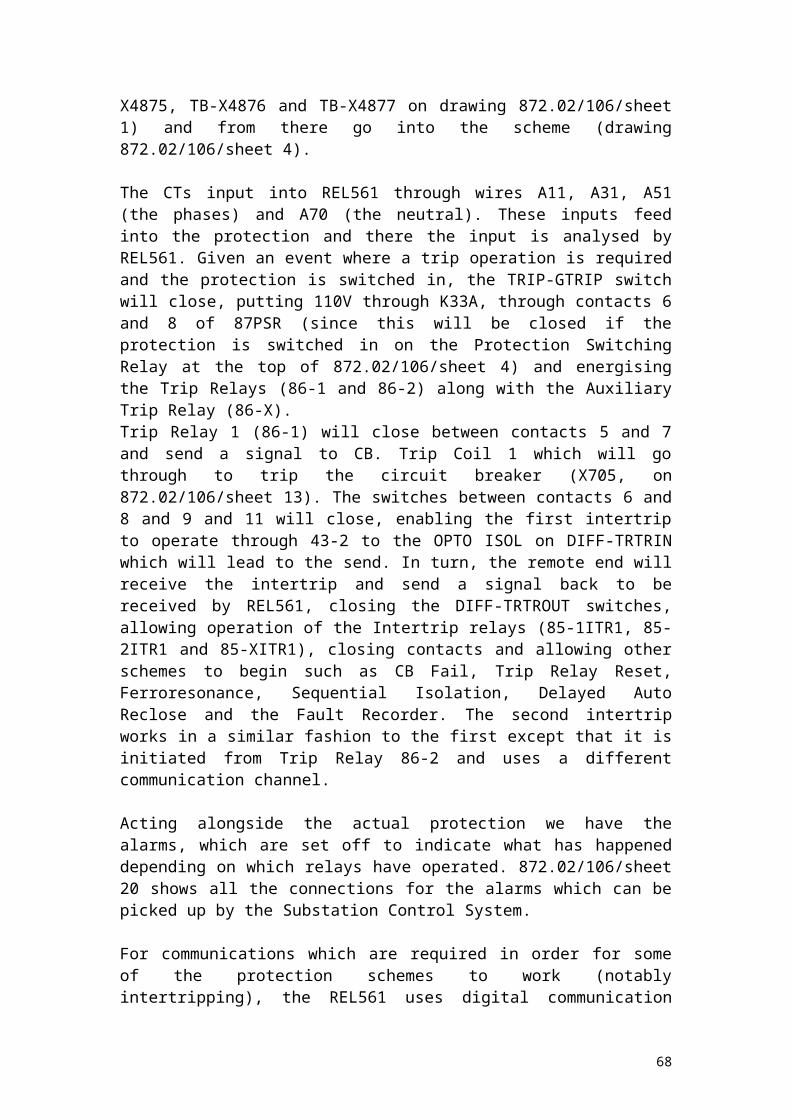
trip if the auxiliary switches on disconnectors X743A or X743B are closed (that is, one of these disconnectors must be closed if there is to be a trip due to one of these) which makes sense as these situations should only occur if the Quadrature Booster is in service. The relays concerned with each of these systems are as follows:
Relay Purpose63-SH BUOS Shunt Unit Buchholz Oil Surge63-S BUOS Series Unit Buchholz Oil Surge49-1CT Series/Shunt Unit Core Temperature High63-R TC/BUTS Tap Changer Selector (A Phase) Oil/Gas Surge63-Y TC/BUTS As above, but B Phase63-B TC/BUTS As above, but C Phase63-R TCD Tap Changer Diverter (A Phase) Oil Surge63-Y TCD As above but B Phase63-B TCD As above but C Phase63-R BUTR Tap Changer Selector Tie Resistor Oil Surge (A Phase)63-Y BUTR As above but B Phase63-B BUTR As above but C Phase
Where ‘BU’ appears in the relay name, the relay is associated with the Buchholz. Settings for these are to be found in the settings sheets in the appendix.
This takes care of most of the protection systems associated with the Quadrature Booster but there are two schemes left to consider, both quite similar – the LV Instantaneous Earth Fault Scheme and the LV Earth Fault Protection Scheme.
LV Earth Fault Schemes.
The LV Instantaneous Earth Fault scheme uses the neutral from the Quadrature Booster, which is earthed and a CT is taken from this and connects into the protection via TB-X4945. These inputs go into relay 50NEF and can trip the Quadrature Booster between contacts 11 and 12, providing that one of the two previously mentioned Disconnectors are closed.
The settings are shown below:
Relay Function Type Settings NotesQB LV E/F Inst. DCD114A Power System Frequency =
50HzObvious
E/F Rating = 1A 1A RelayE/F CT Ratio = 1000:1E/F Characteristic Setting = 0.1
0.1A for operation
E/F Characteristic TM = 1E/F Characteristic Delay = 0.02
Relay will operate if current detected is 0.1A after 0.02s
68

The LV Earth Fault Protection Scheme works in a similar way, using a CT on the neutral of the Quadrature Booster and inputting to TB-X4945. This time, the relay that is inputted to is 51NEXI which, if the switch between contacts 11 and 12 closes, and one of the disconnectors is closed as mentioned previously, then the Quadrature Booster will trip.
Relay Function Type Settings NotesQB LV E/F Delayed
DCD114A Power System Frequency = 50Hz
Obvious
E/F Rating = 1A 1A RelayPole Type = E/FCT Ratio = 1000:1Characteristic Delay = 5.00Summary:Current Setting = 0.1ACharacteristic = EITime Multiplier = 0.1TM
This relay will operate if the current detected exceeds the setting and the time delay is 0.5s
69

Keadby – Grimsby West Circuit.
As mentioned in the circuit selection section, this circuit was chosen simply as it connects to another substation that this project will examine.
In contrast to the Keadby – Cottam 2 circuit previously examined, the Keadby – Grimsby West circuit utilises somewhat older protection systems – notably P10 as the first main protection and SHNB as the second main protection. P10 is an example of Power Line Carrier protection and SHNB is an example of distance protection In this particular case, the distance protection is plain, without acceleration or blocking channels.
Power Line Carrier Protection.
This method of protection is being phased out over the country as National Grid turn to integrated technologies such as those developed by Siemens and the need for line traps decreases.
Power Line Carrier Protection (PLC) works using the power lines to signal the remote end and using the communications to decide if there is a need for an operation or not. To this end, in order to prevent interference from the signal with the actual power signal of 50Hz, another frequency is used, typically in the range of hundreds of kilohertz. Furthermore, to prevent the signal from mixing with the power signal and potentially causing mal-operations of equipment and relays (or even worse, causing damage to the equipment), Line Traps are used to filter the signal and ensure that it travels through the correct circuit – that is, to the protection and not to any other equipment. The high frequency chosen (for the Keadby – Grimsby West feeder it is 132 kHz, but could vary between sites that use this) unfortunately impinges on frequencies set aside by legislation for other purposes and therefore restrictions are in place to prevent the permanent use of this signal, making the system more complicated. To bypass the complications set by legislation, there are guards and starters that prevent transmission of the Power Line Carrier signal unless there is a disturbance and this feature will explained in greater detail later.
Line Traps.
Line Traps are used as filters for Power Line Carrier signals. These units can be seen on feeder circuits up and down the country and are essentially Inductive/Capacitive (LC) circuits in parallel for which the Inductance and Capacitance are carefully selected so that the power signal is left to pass unhindered and the Power Line Carrier sees an infinite resistance and is therefore forced to go through a different path and into the protection as intended – which is known as a band-block filter. To prevent the power signal from travelling down the path intended for the Power Line Carrier signal, a series LC circuit is used which is set to allow the higher frequency signal through, but effectively block the power signal. The following diagram shows the basis how this works:
70

Schematic Diagram of Band Pass Filter Set up. Adapted from " http://en.wikipedia.org/wiki/Image: Bandpass.gif”
The diagram above is not necessarily indicative of how the situation works on National Grid substations, but is a useful aid in describing the action of the filter.
Consider the horizontal line at the bottom of the diagram – this would be our circuit in which both the Power Line Carrier signal and our Power signal travel. Recall that the Power signal is the one that will be at a very high voltage and should be allowed to continue unhindered. Also assume that the signal is travelling from left to right. Up to the point where the parallel circuit is seen, both the Power Line Carrier signal and the Power signal are mixed. Although there will be little interference between the two there will be some and if allowed to continue beyond the line trap then problems could occur with other protection systems.
The parallel circuit is set in such a way that the Power Line Carrier signal is effectively blocked and thus has to find an alternative route. This would be through the series LC circuit that is set to accept the higher frequency signal, but block the lower frequency power signal. The circuit beyond the series circuit would then go into the protection system and the path can be considered complete. For transmission of the signal, the reverse should be true. In order to avoid interference between incoming and outgoing signals, two sets are used and this is the reason why two line traps are seen on such circuits and not just one.
With the difference between the frequencies of the two signals (Hz to hundreds of kHz) there is no requirement to deal with the fact that regardless of how well the band pass filter performs, there will always be some filter roll-off (e.g.: Gibbs Phenomenon, which will not be discussed here).
Power Line Carrier Protection and P10.
P10 (also known as Contraphase P10) compares the phase angles of the fault current at both ends of the line by modulating the high frequency signal that is transmitted as described earlier. The carrier range is 36dB and thus can operate on lines up to 200 miles in length.
71

P10 takes the input of the three phases through the CT and uses them to create a modulating wave, which is made up of positive and negative phase sequence currents (where positive phase sequence results in the phases being in order RYB and negative phase sequence results in the phases being in the order RBY) specifically 5I2 – I1
where I1 is the positive phase sequence current and I2 is the negative phase sequence current.
Under normal conditions where the system is healthy, negative phase sequence currents should be at or near zero as these currents only occur where there are faults in the system. In this circumstance no modulating signal is formed and therefore unmodulated carrier is sent periodically (noting the legislation restrictions) as a communications test to ensure that both ends can still receive/send signals.
Where there is a fault, negative phase sequence currents will be present and thus the modulating signal can be formed and transmitted to the remote end for comparison. The signal taken from the phase sequence currents is squared and transmitted (with the carrier frequency) to the remote end. The modulation is filtered out at the receiving end and the carrier is analysed with the carrier signal at that end and compared.
At both ends, therefore, there will be two signals – one will be it’s own signal and the other will be a received signal from the other end. These are put together and analysed as a whole and the key to this is that the protection is looking for gaps within this signal (to a pre-specified tolerance to avoid mal-operations). For faults within the protected area (an ‘in-zone fault’), gaps will be present and therefore the protection will operate and for faults outside the protected area (a ‘through fault’) the protection will not operate. The diagram below shows how this would work in practice:
72

Diagram of the basic principles of Power Line Carrier Protection. From Network Protection and Automation Guide.
Through fault currents at the two ends of the protected line are in antiphase and hence the signals add to give us the composite signal found on the left-hand side of the diagram. Where there is an internal fault, where the protection is required to trip the circuit breaker, the fault currents are in phase and the composite signal on the right hand side of the diagram is the result, producing gaps and allowing the protection to operate. Without any tolerances, the smallest gap (representing a phase shift of a very small magnitude) would operate the protection, but in reality, a tolerance is added (approximately 300, but this would depend on the circuit) to prevent spurious signals from needlessly operating the protection. This angle is known as the stability angle and prevents tripping for phase differences below this angle.
P10 works using this principle coupled with two starters (Negative Phase Sequence and Positive Phase Sequence) each with high and low set detectors and a marginal guard that will prevent any mal operations due to the resetting of the detectors.
In the event of a disturbance, both starters will have their low set detectors operating and will generate and send their signal to the other end (note that this will be occurring at the other end simultaneously). In the event of a through fault or a minor disturbance, the process will end here, although by doing this it has been established that the disturbance was either minor or not within the protected area. In the event of a
73

fault inside the protected area, both the high set and low set detectors for both starters will have operated and the operation of the high set detectors enables the equipment at both ends to compare the signals they have generated/received through a phase comparator. At this point, if there are gaps in the signal, then tripping of the circuit breakers will be allowed as the high set detectors have operated (both high and low set detectors are required to have operated for tripping to be possible) and this is where the marginal guard comes in. Since it is possible for the detectors to be reset at different times, it is possible that one end is still signalling and the other not, thus artificially generating gaps and causing unwarranted operation of the circuit breakers. The marginal guard simply ensures that there is signal seen for a length of time that will ensure that both detectors at both sides reset.
The use of the starters, detectors and guards are to ensure that not only does the protection work when required, but also that it doesn’t work when operation is not required and that the signalling is used to a minimum as dictated by legislation.
There are both impulse and non-impulse starters so that the protection can operate if a fault develops rapidly (which would be most of the time, theoretically) and if a fault develops over time (such as one due to degradation of equipment like the overhead line).
There are also signalling channels available (intertripping) for operation of the remote end circuit breaker for complete fault removal.
As with all unit protections, P10 only requires CT inputs (A11, A31, A51 and A70) which input into the protection system. From there, all the functions can be traced via the first protection drawing (42/117827). As the major functions of unit protection have already been discussed, they will not be repeated here.
The settings are shown below:
Relay Function Type Setting NotesFirst Main P10 Modulator Squarer =
7.5%PPS Impulse Starter = 30%
Positive Phase Sequence Starter
NPS Impulse Starter = 20%
Negative Phase Sequence Starter
NPS Non-Impulse Starter (xI2) = 3
Non impulse starter
Clock Test = On hour, every hourFrequency = 132 kHz High frequency
signal.
Distance Protection and SHNB (Micromho).
The second main protection on the Keadby – Grimsby West feeder is a distance protection of the Micromho type. The basic principles of how distance protection
74

works have already been covered earlier in this project and there is no need to cover it again. Having examined material available on THR and SHNB, the conclusion is that both relays are very similar and operate in more or less the same way – the only major difference being the way that THR and SHNB cover blocking and acceleration modes – THR utilises a fourth zone, whereas SHNB would use a reverse zone three. Therefore this section will look at how SHNB works in detail, and it can be accepted that, internally, THR works similarly.
The overall scheme is set to plain, which means that there are no blocking or acceleration schemes and each zone will operate as per the basic principles. As with all other distance protections, Micromho takes inputs from CT and VT connections and uses these to calculate impedance as mentioned previously.
This is not completely accurate, as the comparator within SHNB (and THR) actually receives two signals defined as follows:
The following diagram shows where these quantities arise:
Diagram to show mho characteristic. Adapted from Ground Distance Relaying paper by Alexander and Andrichak.
The diagram shows a basic mho characteristic on a Voltage plot (IX versus IR). Z is characteristic of the line itself and is programmed into the relay (see settings) and V and I are measured to produce the vectors shown here. Where IZ – V lies outside of the circle, the protection will not operate and where IZ – V lies inside the circle (or more accurately, the mho characteristic) the protection will operate. It is straightforward to show that if A lags B by any angle up to 1800, then the protection will operate.
The comparator itself does not take the values of A and B directly, they are converted from sine waves to square waves, by amplification and are used in a logic system to calculate if A lags B (operate) or vice-versa (restrain). A counter is placed within the logic system to account for noise that may interfere with the signals. This counter will increment or decrement by 1 for each signal it counts as operate (+) or restrain (-). If the counter gets to 4 or whatever the criterion for operation has been set at then the protection will operate.
75
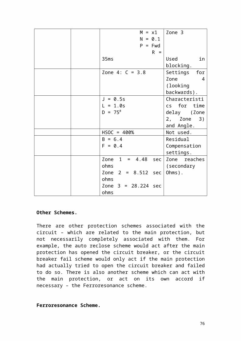
This principle works for any characteristic, be it the circular mho characteristics of zones 1 and 2 or even the lenticular characteristic that zone 3 may take. The equations may change slightly and the use of two or more comparators may be required, but the effect is the same.
Note that this is done on each phase and therefore there will be a comparator per phase per zone (and possibly more depending on the shape of zone three) each performing the tasks mentioned above.
Furthermore, zone three is often set in such a way that a small portion ‘looks’ backward into the substation – this is called an offset mho characteristic and was described in the previous section on distance protection. It provides back up protection for the busbars (although it has not operated for this purpose yet anywhere on the network). Set-ups that employ reverse zones are for blocking and acceleration schemes, which have already been mentioned.
The settings for the second main protection is shown below:
Relay Function Type Setting NotesSecond Main SHNB Coarse Settings: K1 = 4, K2
= 0.6Coarse settings for the zone reaches
Zone 1: K11 = 1, K12 = 0.2, K13 = 0.08, K14 = 1, K15 = 1, K16 = 0
Zone 1 reach
Zone 2: K21 = 2, K22 = 0.4, K23 = 1
Zone 2 reach
Zone 3: K31 = 5, K32 = 0.7, K33 = 1, K34 = 0.5
Zone 3 reach
A/B ratio = 0.84 Lenticular settingt2(ph) = 0.5s, t2 (E) = 0.5s. Operation time for
Zone 2t3(ph) = 1s, t3 (E) = 1s Operation time for
Zone 3Option Select: X = 1, Y = 1 Plain DistanceResidual Compensation: K3 = 2, K4 = 0.9, K5 = 0.06Relay Angle = 85deg Characteristic Line
Angle (from OHL)
76

Keadby - Killingholme – Creyke Beck Teed Circuit.
Of all the circuits discussed at Keadby 400kV substation this is probably the most interesting, having undergone a protection change with the installation of Siemens numerical protections (SIPROTEC). The introduction of the new technology has reduced the amount of protection relays to the three units, busbar protection and the operational tripping – everything else was removed under the protection change.
All three (First Main, Second Main and Backup) are controlled by 3 different units – 7SD523 which is the unit protection (line differential) and backup, 7SA522 (distance protection) and 7SJ64 which is the CB fail protection, CB Control, DAR and Fault Recorder.
All three devices are digital, using up to date technology comprising chiefly of 32-bit microprocessors and optic fibre communications, with a GPS wireless communication system as a second communications method. Faults within the equipment itself are generally automatically detected and dealt with internally. Virtually any parameter regarding protection can be set (one in particular would be that CT wiring becomes less important in that the star points no longer have to be polarity conscious as the protection can be told which direction the star point is in relative to the circuit it is protecting and each end is independent of the other, as long as the setting is correct).
Furthermore, the communications are set up so that one end out of the three can be taken out without compromising the integrity of the other two ends as the communications are set in a ring.
7SD523 – Line Differential Relay.
The 1st Main Protection on the new circuit is a line differential which is essentially a current differential system where the currents are compared with each other and a difference measured leads to an operation as there must be a fault somewhere in the protected section (same basic principle based upon Kirchhoff’s Laws). One of the ends is chosen to be the ‘timekeeper’ which determines the time base and the other ends use this to calculate any delays with respect to this ‘timekeeper’. A precision of 0.5ms can be achieved using these relays and the ‘rough synchronisation’ method mentioned. In addition, time stamping is also used which reduces the tolerances to <5s – quite sufficient for NGC purposes.
As mentioned previously, the Current Differential principle is such that the net flow of all currents flowing into the protected section are zero – this is not strictly true as this basic principle neglects reactive currents due to reactors and capacitors, as well as any magnetising currents that may be present. The equipment is designed to restrain against operation for any such deviations from zero.
The measured currents (restrain and differential) are compared by the protection against a 450 line (somewhat similar to the REL561 mentioned earlier, but without the two line characteristics) where there is a trip/no-trip condition – above the line (where Idiff > I rest) there is a trip and below it there is not. However, the setting is such that it is not possible (on paper!) for a spurious trip as the restrain current takes into account
77

the maximum possible errors in measurements. Each measurement taken is transmitted to the other end(s) so that all end(s) have all the information required for operation/non operation. Another feature of the SIPROTEC Line Differential relay is the ability to perform a charge comparison (I believe that this is unique to this relay) – this is simply a summation of charge flowing into the system (again, net charge would be zero under the conservation of energy/charge principle) using the following equation:
Since charge is a scalar quantity (measured in Coulombs under the SI system) this can be done at very high speed (much higher than a vector comparison of current) – the detraction from this being used as a protection system on its own is that charge comparison is influenced by charge currents from lines and shunt currents from transformers. 7SD523 also includes an overcurrent detection relay as a backup facility (the fact that it can double up as a distance protection is irrelevant as there is another relay that does this) and can be set to any characteristic (see the notes above for the mathematical relationships for Inverse, Very Inverse, Extremely Inverse etc.) and for any value required (see the settings in Appendix C).
A summary of the settings for the 7SD523 unit is shown below:
Relay Function Type Setting NotesFirst Main 7SD523 Functions in use: Differential
Unit Protection, Earth Fault Protection, Phases Unbalanced and Fault Recording
The functions used in the First Main Protection
Idiff pickup values: Low Set = 0.44A; High set = 2.30A
Low and High Set pickup values
Backup Earth Fault: Current Setting = 0.40A; Time dial = 0.39; Curve = Normal Inverse.
Earth Fault Current value. Normal Inverse with Time Delay (see IEC equations).
The nature of the SIPROTEC relays is such that analogue to digital converters are used and that the inputs and outputs from these are digital in nature (Binary inputs).
7SA522 – Distance Protection Relay.
The 2nd Main Protection is a Distance Protection relay that acts as any other distance protection relay such as THR etc. would act. However, this unit also incorporates backup protection (which means that there are, in essence, two backup protections on this circuit) and has the ability to set multiple zones either forward, reverse or non directional reaching, with either a polygonal or mho characteristic.As with the 7SD523, control of specific settings such as the CT star point can be set independent of the other end. Up to six zones can be set (Zones 1 through 5 and a Zone 1b, which is a controlled overreaching zone for auto reclose and/or teleprotection purposes etc.) – Zone 1 remains the instantaneous tripping zone, and
78

zones 2 and 3 remain the traditional zones as per other distance protection relays. The addition of zones 4 and 5 allow for greater flexibility in that these could be set backwards and used in a blocking scheme. Zones 4 and 5 are delayed as zones 2 and 3, and can be set to the time required. Note that the 7SA522 can also utilise power swing detection, to prevent operations for load jumps, short circuits and such like which could bring the load close to encroaching the zones. To do this, there is a power swing range zone which will prevent operation should the load swing into this region and beyond into the fault region, so long as the load swings back out. In the event of a fault, the load will not swing through this power swing region and therefore the protection will recognise this as a fault.
The following shows a brief summary of the settings for this protection:
Relay Function Type Setting NotesSecond Main 7SA522 Summary of functions in use:
Distance Protection, Backup Earth Fault Protection, Switch on to Fault (trip on closing), Phases unbalanced and Fault Locator.
The functions in use for this protection. Note that switch on to fault is also known as trip on close – which will trip the circuit if the fault has not been cleared and DAR is present.
Distance Protection Zones (all Ohms): Z1 = 7.9326, Z1B = 25.2378, Z2 = 25.2378, Z4 = 26.568, Z5 (rev) = 2.6568, Z5 (fwd) = 26.568, Z3 (rev, blocking) = 30.843.
The zone reaches. The impedances shown are in secondary ohms.
Earth Resistances: Z1, Z1B, Z2 = 5.626; Z4, Z5 (rev + fwd), Z3 = 6.5862
Earth path resistances for earth faults in distance protection – secondary ohms.
Timers: Z1, Z1B = 0s, Z2 = 0.5s; Z4, Z5 and Z3 = 1.00s
Timers – this is standard.
SOTF Pickup = 5.1A This is the current level for SOTF to retrip the circuit on close (no time delay).
Earth Fault overcurrent: Pickup = 0.4A, Time dial = 0.39s.
Backup protection settings – see IEC curves.
Zone characteristics: All quadrilateral
No mho characteristics – no tilt for Z1.
79
7SJ64 – Multi-Function Unit.
This is the third and final new unit on the circuit which controls the extra schemes of the protection beyond first and second main and backup (such as DAR, Synchronising, Sequential Isolation etc.). This unit offers the same level of control as the other two devices and can be set to Definite Minimum time or an inverse characteristic with or without time delay and/or direction.
The easiest method to illustrate the uses of the relay would be to examine the settings – shown below:
Relay Function Type Setting NotesCircuit Breaker Unit
7SJ645 Functions available: Auto Reclosing, DAR synchronising, Manual Synchronisation, Sequential Isolation, Circuit Breaker Fail, Trip Circuit Supervision, Fault Recorder
These are the functions available to the unit – this covers all the other schemes that the main protections do not and could control Busbar protection if programmed correctly (not used here).
Auto Reclose: Relay Dead time = 15.0s, Reclaim Time = 2.0s, Synchronising angle = 350
The most important quantity is the synchronising angle – this is to prevent damage to equipment.
Circuit Breaker Fail: Current Setting = 0.2A, Time Delay = 0.17s
If the circuit breaker fails, this will operate in 0.17s and execute switching out of other circuits (including busbars) to prevent any further damage.
DAR: tDead = 15.00s, tLockout = 2.00s, tReclaim = 2.00s, tIDLockout = 60s, TD10 = 10s, TD120 = 70s.
The DAR settings are much the same as for the other circuits – NGC standard.
The drawings show how the system works – which aside from the potential confusion arising from use of Binary Inputs/Outputs, are similar to the way other feeders do.
80
Grimsby West 400kV Substation
Overview
Grimsby West 400kV is situated just outside of the fishing port of Grimsby, near the village of Aylesby. The site itself is unremarkable, save that it is shared by YEDL, which has a 132kV substation located opposite. The substation is obscured by woodland, which provides a screen for nearby houses and fields.
Grimsby West is an outdoor substation, with a mixture of equipment ranging from oil based switchgear and air based switchgear. An interesting feature is that one of the circuit breakers (FEX-2 type) is currently under an OESB, which requires a clearance distance of the entire compound should it be called upon to operate. It is a single switch substation, with two circuits leading out (Keadby and South Humber Bank) and two 400/132kV transformers. The overview of the substation can be found in appendix D and the circuits at the substation are listed below:
Circuit Approximate date of Commissioning and supporting details
Grimsby West – Keadby June 1969 at Keadby 400kV, best estimates would be the same.
Grimsby West – South Humber Bank No commissioning files available on site.Grimsby West 400kV – 132kV (SGT1) No commissioning files available on site.Grimsby West 400kV – 132kV (SGT2) No commissioning files available on site.
The following tables show the inventory of the protection relays currently in use at Grimsby West 400kV.
81
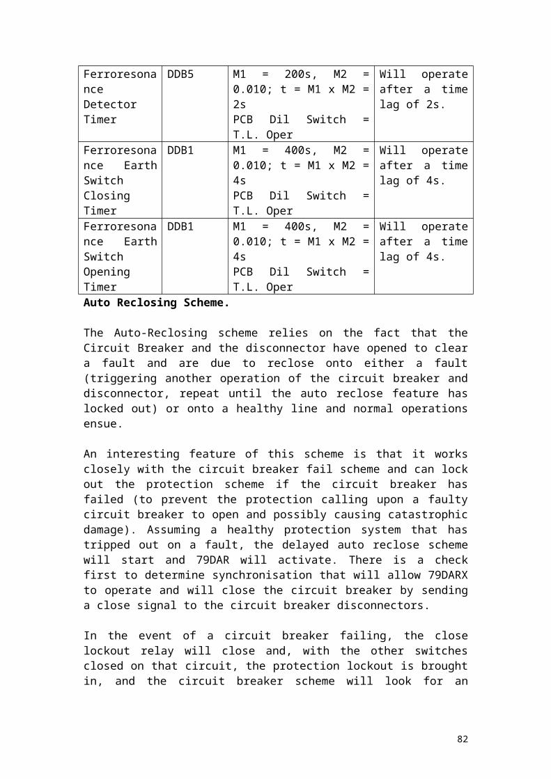
Mesh Corner 1 and 2.
The protection relays are exactly the same for both Mesh Corners at Grimsby West 400kV substation and therefore the following list shows the relays at Mesh Corner 1 and any common relays for both corners:
Rack Name Type Manufacturer NotesMesh Corner (Common?)
MVAG(MVAG21D1ADA9001A)
Alstom CBVB4/CBVA1
MVAW(MVAW21B1AB0543A)
Alstom DARIN1/DAROUT1
MVAA(MVAA21B1AA9004A)
Alstom INCHB1/CCB1
MVAA(MVAA21B1AA0753A)
Alstom OPHDA1/CDA1
MVAA(MVAA21B1AA0751A)
Alstom DARIS1/DAROS1
MVAA(MVAA21B1AA0753A)
Alstom OPLA1/OPHDB1
MVAG(MVAG21D1ADA9001A)
Alstom CBVB1/CBVA2
MVAW(MVAW21B1AB0543A)
Alstom DARIN2/DAROUT2
MVAA(MVAA21B1AA9004A)
Alstom INCHB2/CCB2
MVAA(MVAA21B1AA0753A)
Alstom OPHDA2/CDA2
MVAA(MVAA21B1AA0751A)
Alstom DARIS2/DAROS2
MVAA(MVAA21B1AA0753A)
Alstom OPLA2/OPHDB2
LFAA103 GEC 2 of theseMVAA(MVAA21B1AA0751A)
Alstom ASC1/ASC2
MVAA(MVAA21B1AA0751A)
Alstom CNTE1/CNTE2
MVAA(MVAA21B1AA0751A)
Alstom ASIP1/ASIP2
Sequential Isolation
MVAX(MVAX12B1CA0753A)
Alstom PSSR
MVAA(MVAA11B1AA0783C)
Alstom SDAR
MVTT(MVTT14B1BB0772C)
Alstom SDTDR
Auto-Isolation
MCAG(MCAG19C1AE0013A)
Alstom NEFI (X113)
MVAG(MVAG11B1APA9001A)
Alstom VTCI (X113)
82

MVTT(MVTT14B1BB0772C)
Alstom T10 (X113)
MVAA(MVAA11B1BA0731C)
Alstom TIR (X113)
MCAG(MCAG19C1AE0013A)
Alstom NEFI (X213)
MVAG(MVAG11B1APA9001A)
Alstom VTCI (X213)
MVTT(MVTT14B1BB0772C)
Alstom T10 (X213)
MVAA(MVAA11B1BA0731C)
Alstom TIR (X213)
CB Control MVAW(MVAW21B1AB0541A)
Alstom IPO
MVAA(MVAA11B1AA0533C)
Alstom CLOX
MVAA(MVAA11B1AA0531C)
Alstom FT1X, PNTX, FT2X (3 relays)
CB Fail MVAJ(MVAJ21D1BB0751B)
Alstom Z1 TRR, Z2 TRR (2 relays)
MVAX(MVAX12B1CA0753A)
Alstom PSSR 12, PSSR 22 (2 relays)
MVAJ(MVAJ 25D1FB0773C)
Alstom BFTR1, BFTR2 (2 relays)
MVAX(MVAX12B1CA0753A)
Alstom PSSR13, PSSR 23 (2 relays)
PCHN GEC BFCCK1, 2 / BFCCK 2, 1
CDTP101 UnmarkedMVAX(MVAX12B1CA0753A)
Alstom PSSR11
MVAJ(MVAJ21D1GB0780B)
Alstom BFTRR
MVAX(MVAX12B1CA0753A)
Alstom PSSR1
Mesh Corner 1
F14E Reyrolle 400kV Connections Trip 1 + 2 (2 relays)
TDS Reyrolle 400kV Connections CT Supervision alarm time lag
E/B50 (1 per phase) Reyrolle 400kV Connections CT Supervision
Unknown type 400kV Connections Differential Protection Relay 2
B52 Reyrolle Unknown (x2)3B3 (1 per phase) Reyrolle 400kV Connections
Differential Protection Relay 1
83
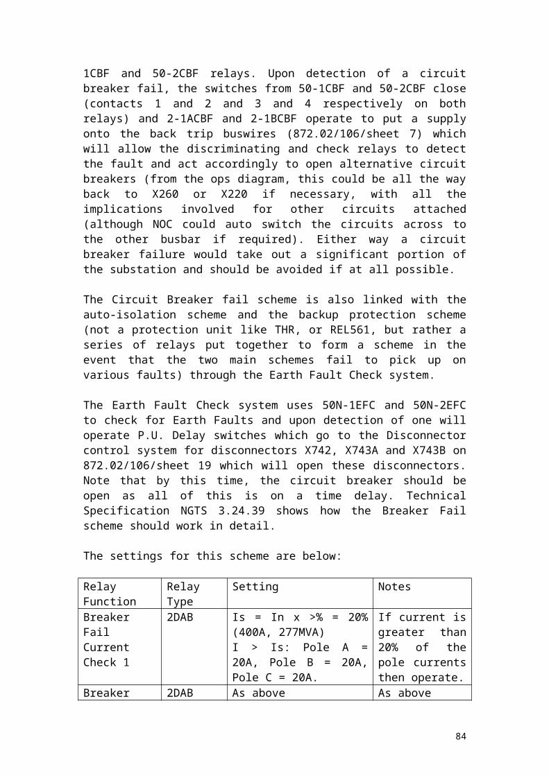
MVAX(MVAX12B1CA0753A)
Alstom PSSR
MVAJ(MVAJ55H1JB0846B)
Alstom TR3, TR3
84

SGT 1.
The list below shows the protection relays installed on the SGT1 circuit at Grimsby West 400kV substation:
Rack Name Type Manufacturer NotesSGT1 F14E Reyrolle Transformer trip 1 + 2
(2 relays)TDS Reyrolle Overcurrent stage 2 time
lagB12 Reyrolle Winding temperature
trip / Buchholz surgeB69 (3 phase) Reyrolle MHJVAJ(VAJZ13ZG2242BA)
GEC Tripping
Unknown type (3 phase) Transformer differential protection relay 2
TJV GEC 3 Phase Overcurrent3B3 (3 phase) Reyrolle Transformer differential
protection relay 1
85

Grimsby West – Keadby Circuit.
The following list shows the protection relays in use for the Grimsby West – Keadby circuit at Grimsby West 400kV Substation:
Rack Name Type Manufacturer NotesKeadby Common Protection
TDS Auto Reset
MVAA(MVAA11F1AA0551A)
Alstom RMRX
MVAA(MVAA11D1BA0803A)
Alstom TD120 Aux Relay
MVAA(MVAA11D1BA0805A)
Alstom FRD
VTT(VTT14YP5218AA)
GEC Static Time Delay
Keadby Backup Protection
MVAX(MVAX12B1C0753A)
Alstom PSSR1
MVAJ(MVAJ25D1FB0775C)
Alstom TR2
MVAJ(MVAJ25D1FB0773C)
Alstom TR1
MCGG(MCGG22D1CB0753C)
Alstom EFRIT EF
Keadby Feeder End Protection
MFAC(MFAC34F1AA9011A)
Alstom Voltage
MVAX(MVAX12B1CA0753A)
Alstom PSSR
MVAJ(MVAJ25D1F0775C)
Alstom TR2
MVAJ(MVAJ25D1F0773C)
Alstom TR1
Keadby 1st
MainTR231 Reyrolle TR1
TR231 Reyrolle TR2AR101 Reyrolle TRAUXP10 PPBB101TR431 Reyrolle PSR + KeyB52 Reyrolle PSSRTR512 Reyrolle USB
Keadby 2nd
MainAR101 Reyrolle UMR
DDB1 Reyrolle VMRTDTR231 Reyrolle TR1TR231 Reyrolle TR2AR101 Reyrolle TRAUX
86

Micromho SHNB102TR431 Reyrolle PSR + KeyB52 Reyrolle PSSRTR512 Reyrolle USB
2nd Intertrip TR131 Reyrolle IRTR1TR131 Reyrolle IRTR2CTS ReyrolleB52 Reyrolle PSSRAR111 Reyrolle IRFR
1st Intertrip TR131 Reyrolle IRTR1TR131 Reyrolle IRTR2CTS ReyrolleB52 Reyrolle PSSRAR111 Reyrolle IRFR
OP TrippingKeadby 1st MVAA
(MVAA11B1CR0785B)Alstom DBI
MVAJ(MVAJ21DGB0777B)
Alstom A1, A2, OTRR (3 relays)
MVAX(MVAX12B1CA0753A)
Alstom TSSR
MMLZ(MMLZ07D1AA0751A)
Alstom CTS
MVAA(MVAA11B1BA0786C)
Alstom OTRFR
MVAJ(MVAJ25D1FB0773C)
Alstom OTRTR
Keadby 2nd MVAA(MVAA11B1CR0785B)
Alstom DBI
MVAJ(MVAJ21DGB0777B)
Alstom A1, A2 (2 relays)
MMLZ(MMLZ07D1AA0751A)
Alstom CTS
MVAA(MVAA11B1BA0786C)
Alstom OTRFR
MVAJ(MVAJ25D1FB0773C)
Alstom OTRTR
87
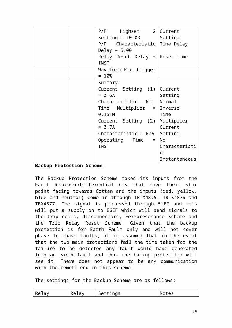
Grimsby West – South Humber Bank Circuit.
The relays are identical to the Keadby circuit relays with the following exceptions:
Rack Name Type Manufacturer Notes1st Main REL 561 ABB Plus associated relays2nd Main REZ 1 ABB Plus associated relays2nd Intertrip Unknown ABB ABB relays
88
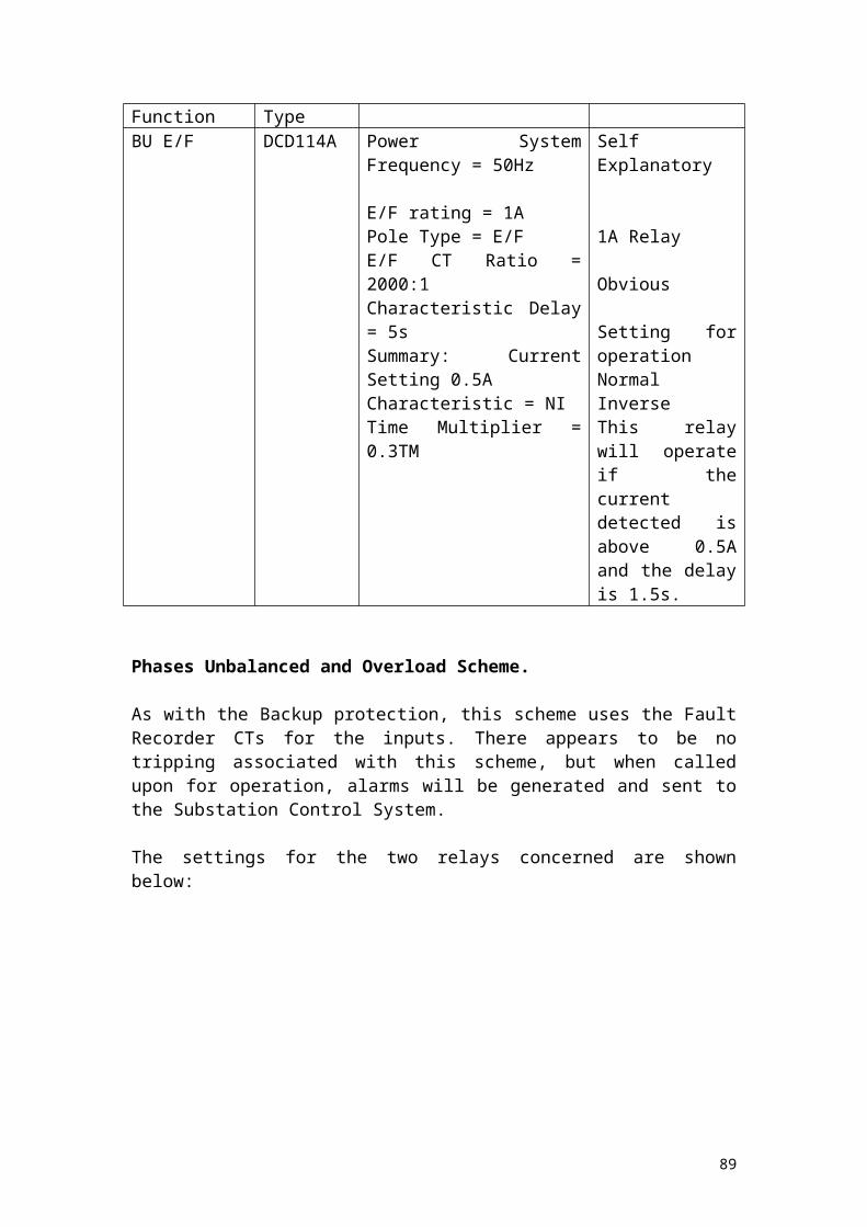
Circuit Selection.
Unfortunately it is not feasible, nor within the bounds of the project to examine all the circuits at Grimsby West 400kV Substation, and thus only a sample will be taken to be examined in depth. Therefore only Mesh Corner 1 (with mention of the Keadby Feeder) will be discussed.
89

Mesh Corner 1 and Keadby Feeder Circuit.
The main reason for the selection of this circuit is not only the fact that the feeder links to another substation examined in this project, but to also discuss the mesh corner protection.
The feeder itself is quite unremarkable – in fact examination of the Keadby – Grimsby West Circuit above shows that the settings are exactly the same and thus discussion here will be limited to the mesh corner protection.
The idea behind Mesh Corner substations was to allow flexibility in circuit selection and at the same time reduce the cost of the primary plant (the increase in the number of protection relays goes no way to offset the lower cost of the switchgear). In comparison to a double busbar station, the cost would be over half (but still a significant saving). This has rung somewhat true, but brings on a greater risk to the switchgear as more operations are required to switch circuits out and prevent large scale losses in the event of a fault. A fault on a feeder would result in local and remote breakers tripping in a double busbar substation, but on a mesh corner, there would be operation of up to four circuit breakers (two mesh breakers, remote end breaker, LV transformer breaker) before isolation of the faulted circuit can take place and the circuit breakers closed to restore system integrity. Thus the switchgear must be reliable. This leads to a greater focus on the protection ‘getting it right’ and making sure that the right piece of switchgear operates at the right time – it would be quite easy for something to go wrong and end up opening most if not all of the substation should a breaker fail or the timing be off. A fully working, reliable mesh corner substation however, more than justifies the inherent limitations introduced.
Grimsby West, however, is not a full Mesh Corner substation but rather utilises two Mesh Corners in a single switch method. All the switching that is required (obviously, not including operational switching for maintenance purposes which is always done either locally or remotely) is automatic, making the use of LFAA relays. One key thing to note about Mesh Corners is the CT positioning – the areas set up by the CTs for protection and switching purposes overlap so no piece of switchgear or circuit lies unprotected. This is incredibly important when considering a full 4-corner mesh substation, like Aldwarke 275kV.
The settings for the LFAA relays are confusing and therefore will not be reproduced or discussed here – but may be included in an addendum to another part of the project. Instead, included in Appendix D is the technical guidance notes TGN 104 and TGN 119, which deal with LFAA relays and mesh corner substations.
90

Aldwarke 275kV Substation
Overview
Aldwarke 275kV substation is situated near Rotherham next to the river Don on the site of a Corus steel works. The most notable features of the substation is that it supplies the steel works via 5 transformers (this is due to the nature of the steel works requirement for a supply – even though it is at a relatively low voltage (33kV) there is extensive protection on both sides due to the nature of their waveform as they use arc furnaces). There are two feeders out of the substation – to Brinsworth and West Melton as part of the Sheffield ring – a very important section of the National Grid system as there is much industry in the area. The surrounding area is principally industrial, with the steel works and other fabrication industries locally. There are a couple of retail parks a short distance away and a recreational field on the opposite bank of the river. Appendix A shows a location map for the substation.
The switchgear is mainly older OCB types, and there are in use some different types of isolators (these can be seen on the ops diagram in Appendix B) – these differ from the centre rotating post type in that there are two arms that swing together to complete the circuit.
The following table shows the circuits at Aldwarke 275kV substation with some commissioning details (limited, as the data was unavailable):
Circuit Approximate date of Commissioning and Supporting Details
SGT1A 1970 – Maintenance details – this is the earliest record on site.
SGT1B 1978 – CT Mag Curve testSGT2 UnknownSGT3 UnknownSGT4 UnknownAldwarke – West Melton UnknownAldwarke – Brinsworth UnknownMesh Corner 1 1970 – This must have been here for
SGT1AMesh Corner 2 As SGT1BMesh Corner 3 UnknownMesh Corner 4 UnknownOther Items of Interest Approximate date of Commissioning
and supporting detailsDAR October 2003 – DAR design intent
document.
The dates are not at all accurate, as commissioning records were unavailable on site. However, the site must have been around prior to 1970, given the equipment present and the age of the Corus Steel Factory. The following tables show the inventory of the protection relays at Aldwarke 275kV substation:
91

Aldwarke – West Melton.
The following list shows the relays in use on the Aldwarke – West Melton circuit at Aldwarke 275kV substation:
Rack Name Relay Type Manufacturer Notes1st Main MVAA
(MVAA11B1AA0783A)Alstom TRAUX
MVAJ(MVAJ25D1FB0773B)
Alstom TR2, TR1 (2 relays)
Microphase FM Migrated to EnergisMVAJ(MVAJ21D1BA0754A)
Alstom USB
MVAX(MVAX12B1CA0753A)
Alstom PSSR
MMLZ(MMLZ03B1AA0001A)
Alstom PIO
MVAJ(MVAJ34D1DB0754A)
Alstom PSR
1st Intertrip MMLZ(MMLZ07D1AA0751A)
Alstom CTS
MVAX(MVAX12B1CA0753A)
Alstom PSSR
MVAW(MVAW02H1NB0753A)
Alstom I/T TRIP
2nd Intertrip MMLZ(MMLZ07D1AA0751A)
Alstom CTS
MVAX(MVAX12B1CA0753A)
Alstom PSSR
MVAW(MVAW02H1NB0753A)
Alstom I/T TRIP
2nd Main MVAG(MVAG11BA5A0751B)
Alstom VMR
MVTT(MVTT14B1BA0772B)
Alstom VMRTD
MVAA(MVAA11B1AA0783A)
Alstom TRAUX
MVAJ(MVAJ25D1FB0773B)
Alstom TR1, TR2 (2 relays)
Micromho SHNB102MVAJ(MVAJ21D1BA0754A)
Alstom USB
MVAX(MVAX12B1CA0753A)
Alstom PSSR
MMLZ(MMLZ03B1AA0001A)
Alstom PIO
MVAJ(MVAJ34D1DB0754A)
Alstom PSR
Feeder End FGL Reyrolle CC Protection 3 Phase
92

VTT (11ZR2043C) GEC Static Time DelayFLD Reyrolle TrippingB52 Reyrolle Feeder End Supply
Supervision FailCF2 Reyrolle Phases Unbalanced
Backup CDG (31FP1512JJ5) GEC 2 Phase + EF O/CVAJ (X12SP1103D) GEC TrippingVAX (12AP1B) GEC DC Supply Supervision
FailFSL Overload Alarm Relay
93

SGT 4 (SGT3 and CB S30).
The following list shows the protection relays on the SGT 4 circuit, the SGT3 circuit and Mesh Breaker S30:
Rack Name Relay Type Manufacturer NotesSGT4 CDG (SPEC3FP1204G) GEC 2 Stage O/C (3 phase)
CAG (39AP3A5) GEC High Set O/C Main (3 phase)
CAG (39AP3A5) GEC High Set O/C 2nd (3 phase)
CAA (SPEC23BP163A) GEC Buchholz and Aux. Buchholz.
FAC (14AP111A5) GEC HV REF2DAB Current Check Reyrolle Tap Changer Diverter
MonitorAR111 Reyrolle Tap Changer Diverter
Monitor FaultCAA (11YP3604CB) GEC Winding TemperatureVAJ (X12SP2241HA) GEC Tripping (2 relays)
CB S30 C (Interposing) GEC Trip Circuit SupervisionCDG (31FP284BF) GEC 2 Phase + EF O/CVAJ (X12SP2241HA) GEC Tripping
SGT3 CDG (SPEC3FP1204G) GEC 3 Phase Overcurrent (Inverse)
VAT (SPEC14AP149T) GEC Definite Time O/C Stage 2
CAA (33BP20B) GEC Main and Aux. Buchholz
FAC Circulating Current Differential Relay
CAG (39AP11A) GEC Inst. O/C (High Set O/C 1) 3 Phase.
CAA (11YP3604CB) GEC AuxiliaryVAJ (X12SP132H) GEC Tripping (2 relays)CAG (39AP18A5) GEC 3 Phase High Set O/C 1
94

Aldwarke – Brinsworth.
The following list shows the protection relays on the Aldwarke – Brinsworth circuit:
Rack Name Relay Type Manufacturer Notes1st Main P10 PPBB101
MVAA(MVAA21B1AA0557A)
Alstom PSR AX + BX
MVAJ(MVAJ34D1DB0755A)
Alstom PSR
MVAX(MVAX12B1CA0753A)
Alstom PSSR
MVAA(MVAA16B1AA0763A)
Alstom USB1
MVAJ(MVAJ24D1FB0773B)
Alstom TR2 + TR1 (2 relays)
MVAA(MVAA11B1EL0783A)
Alstom TRAUX
1st Intertrip MVAJ(MVAJ14D1GB0771A)
Alstom IRTR1 + 2 (2 relays)
MVAA(MVAA11B1BL0753A)
Alstom IRFR
CTS Channel TestMVAX(MVAX12B1CA0753A)
Alstom PSSR
Bover Box (unknown) ABB Unknown purpose2nd Intertrip MVAJ
(MVAJ14D1GB0771A)Alstom IRTR 1 + 2 (2 relays)
MVAA(MVAA11B1B20753A)
Alstom IRFR
CTS Channel TestMVAX(MVAX12B1CA0753A)
Alstom PSSR
2nd Main MVTT(MVTT14B1BA0764A)
Alstom VTFTD
MVAA(MVAA11B1BA0782A)
Alstom VTFF
MVAA(MVAA11B1BA0782A)
Alstom DARLO
THR Distance ProtectionMVAA(MVAA21B1AA0557A)
Alstom PSR AX + BX
MVAJ(MVAJ34D1DB0755A)
Alstom PSR
MVAX(MVAX12B1CA0753A)
Alstom PSSR
MVAJ(MVAJ24D1FB0773B)
Alstom TR2 + TR1 (2 relays)
95

MVAA(MVAA11B1E20783A)
Alstom TRAUX
Backup CDG (16AP0008A5) GEC EFVAJ (X12SP1103D) GEC TRIPPINGVAX (12AP1B) GEC DC Supply FailF52 Reyrolle Overload Alarm Relay
Feeder End Protection
FGL Reyrolle Circulating Current (3 phase)
VTT (11ZR2043C) GEC Static Time DelayLTC3 Tripping relayB52 Reyrolle DC Supply FailCF2 Phases Unbalanced
96
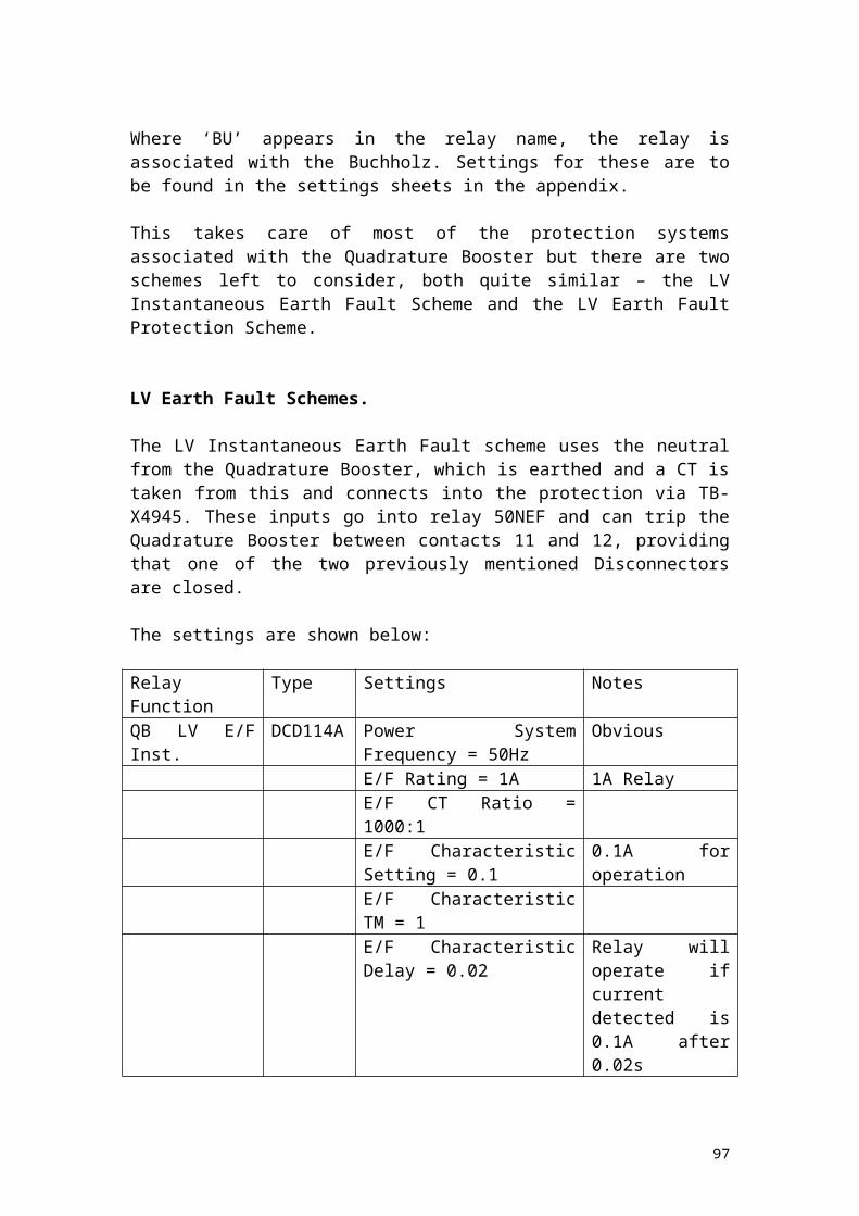
Mesh Corner 3 and CB S20.
The following list shows the protection relays on the Mesh Corner 3 circuit and Mesh Breaker S20:
Rack Name Relay Type Manufacturer NotesMesh Corner 3
FAC (34PP101A5) GEC MC3 CC1
FAC (34PP101A5) GEC MC3 CC2VAJ (X12SP133H) GEC Tripping 1VAJ (X12SP1101D) GEC Tripping 2MVAA(MVAA11B1BA0531A)
Alstom Unmarked
VAX (12AP1B) GEC BB Prot’n DC Supply Fail Zone 3 (2 relays)
VTT (31AP5B5) GEC BB SupervisoryVTT (11NR35A) GEC Static Time Delay
CB S20 CDG (31FP2844B5) GEC 2 Phase + EF O/CVAJ (X12SP2241DA) GEC TrippingVAX (31BP2022B) GEC Trip Circuit SupervisionVAX (31BP22B) GEC J
97
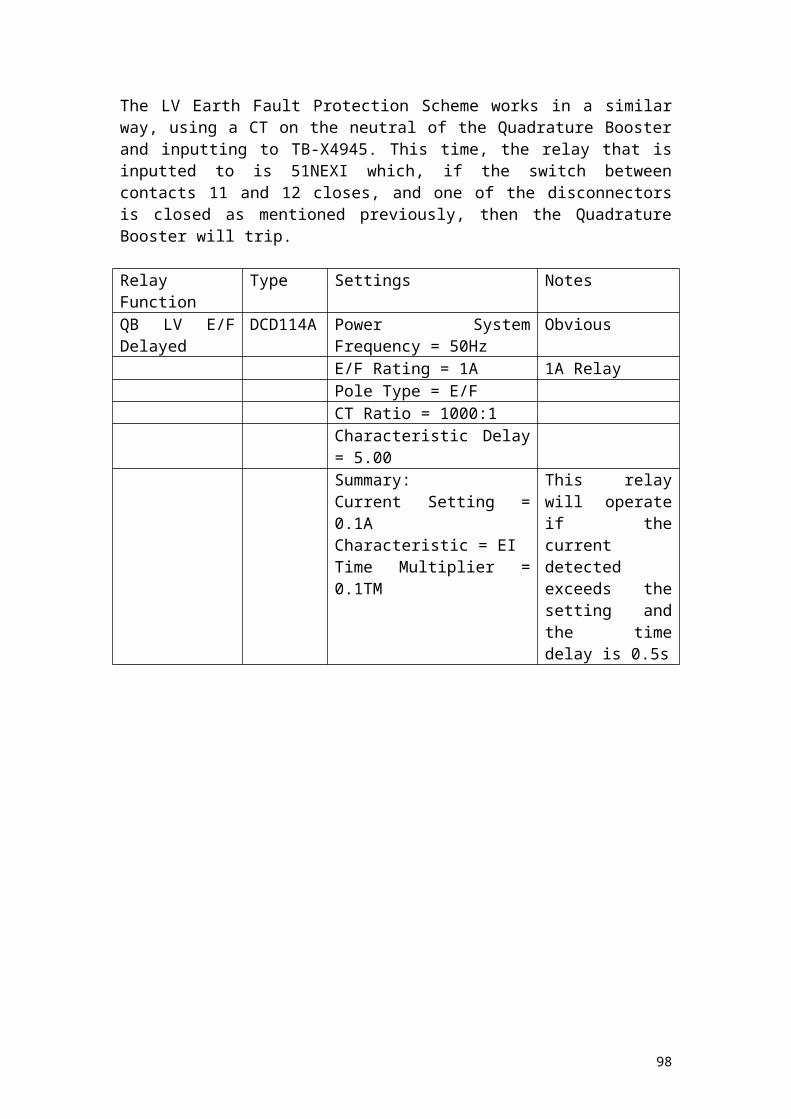
Mesh Corner 2, SGT 2 and CB S10.
The following list shows the protection relays on the Mesh Corner 2 circuit, SGT 2 and Mesh Breaker S20 circuits:
Rack Name Relay Type Manufacturer NotesMesh Corner 2
FV2 3 Phase Protection Relay
FGL Circulating CurrentVAJ (X12SP2241DA) GEC Tripping (2 relays)VAX (12NR1B) GEC DC Supply Supervision
(2 relays)VTX (31AP2005B5) GEC Busbar SupervisoryVTT (11NG2037A) GEC Trip Reset Timer (10s)VTT (11NR2035A) GEC Trip Reset Timer (70s)MVAA(MVAA11B1BA0531A)
Alstom Unmarked
SGT2 CAG (69DP2004A5) GEC Inst. O/C (2 relays)PBO 3 phase O/C relayCAA (11YP3604CB) GEC Winding TemperatureFGL REFCAG (39AF3A5) GEC Inst. O/CF2 Reyrolle Main + Aux. BuchholzAKA2 Stage 2 TimerVAJ (X12SP2241DA) GEC Tripping 1 + 2 (2 relays)
98
Mesh Corner 1, SGT 1A and CB S10.
The following list shows the protection relays on the Mesh Corner 1, SGT 1A and Mesh Breaker S10 circuits:
Rack Name Relay Type Manufacturer NotesCB S10 CDG (31FP2844B5) GEC 2 Phase O/C + EF
VAJ (X12SP2241DA) GEC TrippingVAX (31BP2022B) GEC Trip Circuit Supervision
(2 relays)MC 1 FV2 MC Protection Relay
FGL Circulating Current Protection (3 phase)
VAJ (X12SP2241DA) GEC Tripping (2 relays)VAX (12NR1B) GEC DC Supply Supervision
(2 relays)VTX (31AP2005B5) GEC Busbar SupervisoryVTT (11NG2037A) GEC Trip Reset Timer (10s)VTT (11NR2035A) GEC Trip Reset Timer (70s)MVAA(MVAA11B1BA0531A)
Alstom TRROR
SGT1A PBO O/C Relay (3 Phase)AKA Time Lag RelayFGL REFFGL O/C Relay (3 Phase)CAG (39AP18A) GEC Inst. O/C2DAB Reyrolle Tap Changer Diverter
MonitorAR111 Reyrolle Tap Changer Diverter
Monitor FaultVAJ (X12SP184H) GEC TrippingFSL High Set O/C (3 Phase)LTC2 Tripping (2 relays)
99

Mesh Corner 4, SGT 1B and CB S40.
The following list shows the protection relays on the Mesh Corner 4 circuit, SGT 1B and Mesh Breaker S40 circuits:
Rack Name Relay Type Manufacturer NotesSGT1A CAG (69DP2004A5) GEC O/C Guard and High Set
O/C 1PBO O/C Relay (3 Phase)CAA (11YP3604CB) GEC Winding TemperatureFGL REFCAG (39AP18A) GEC High Set O/C 2F2 Reyrolle Main + Aux. BuchholzAKA2 Time Lag RelayVAJ (X12SF2241DA) GEC Tripping (2 relays)
CB S40 CDG (31FP2844B5) GEC 2 Phase O/C + EFVAJ (X12SP2241DA) GEC TrippingVAX (31BP2022B) GEC Trip Circuit Supervision
(2 relays)MC4 FAC (34PP101A5) GEC CC1 (3 Phase)
FAC (34PP1A5) GEC CC2 (3 Phase)VAJ (X12SP133H) GEC TrippingVAJ (X12SP1101D) GEC TrippingMVAA(MVAA11B1BA0531A)
Alstom Unmarked (3 relays)
VAX (12AP1B) GEC JVTX (31AP5B5) GEC Busbar SupervisoryVAX (12AP1B) GEC DC Supply FailMVTT(MVTT14J1NC0751E)
Alstom TD10
VTT (11NR35A) GEC Static Time Delay
100

CB Fail and Auto Switching.
The following relays are with regard to CB Fail protection and the Auto switching relays, which are housed separately from the other circuits.
Rack Name Relay Type Manufacturer NotesS10 through S40 all the same
CTIG (68D6SA5C)
VTT (43D45A1A)VAX (12NR1B) GEC DC Supply Supervision
MC1 through MC4 all the same
VAJ (11BP2241DA) GEC BFTR
VAX (12NR1B) GEC DC Supply SupervisionVAJ (Z13AP2241AA) GEC TrippingVAX (12NR1B) GEC Trip Relay Reset DC
Supply SupervisionMesh Auto Switching
MVAA(MVAAJ1JA0851C)
Alstom IP 1, 2, 3 (3 relays, but only IP3 for MC1, SGT1B)
D25 GEC Switching relay (black box)
XR309 Reyrolle FRD (Not on MC1 or 2)
101

Circuit Selection.
Unfortunately it is not feasible, nor within the bounds of the project to examine all the circuits at Aldwarke 275kV Substation, and thus only a sample will be taken to be examined in depth. Therefore only Mesh Corner protection will be discussed.
102
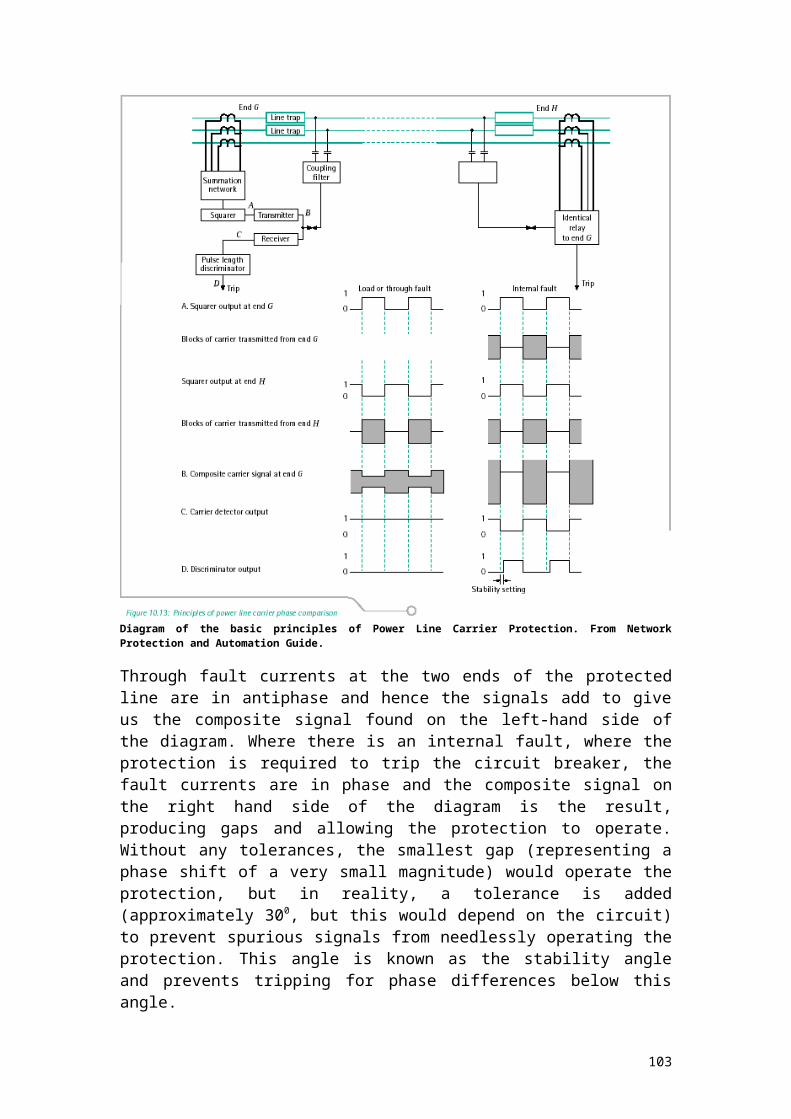
Aldwarke 275kV Substation and Mesh Corner Protection.
As previously mentioned, Mesh Corner Substations provide the same flexibility as Double Busbar Substations but use approximately half of the switchgear. This leads to a compact substation with the trade-off of a very complex protection system that replaces busbar protection (although in some ways it could be considered analogous to it).
The key, as mentioned previously, is that the CTs set up zones of protection between them, using buswires and auxiliary switches to ensure that the right CT is part of the right zone (no need for a feeder CT to be part of the zone if the feeder breaker is open for example) and the inputs feed directly into circulating current relays which can then determine, using the Merz-Price principle (an extension of Kirchhoff’s laws) to determine whether or not an operation is required. Auxiliary switches on plant (isolators and/or circuit breakers) dictate which CTs would be forming which zone with which other CTs dependent on which circuits are in use. This would appear on face value to be quite complex, but given the point that the zones must overlap, the arrangements of the CTs are limited.
From there, the DC circuits determine which breakers must operate and from there which isolators must operate to switch the (now dead) circuit out before automatically reclosing the breakers on to a (now healthy) circuit and allowing things to proceed normally. The DC circuits also determine if other schemes (ferroresonance etc.) need to be energised for operation and a glance at the settings shows quite clearly how this works for a given mesh corner (in this case, the mesh corner is number 3).
Intertripping is controlled (as in most cases) by the isolators – if the isolator is open, intertripping is blocked as there is no need for an intertrip to be sent to the remote end if the local line isolator is open – the circuit must be out for that isolator to be open.
The following table shows a summary of the settings for mesh corner protection for Mesh Corner 3 (and could be assumed to be the same or at least similar to the other corners):
Relay Function Type Setting NotesMesh Corner Protection 1
FAC34 175V, Resistance = 144 Ohms (this equals approximately 1.22A)
Voltage operated relay – wired across the CT wiring not with the CT wiring.
Mesh Corner Protection 2
FAC34 As above As above.
National Grid tends not to use voltage-operated relays in new installations, but older substations like Aldwarke may have them installed.
103

Conclusions/other comments.
A time constraint has prevented an in depth look at two of the three substations mentioned and this is disappointing, as there is a wealth of information regarding protection and a lot can be learned simply by observing the drawings and performing maintenance on the various circuits. This project was designed to be simply background information to some of the circuits at the three substations examined.
Having spent a lot of time at Keadby 400kV substation, the information was relatively easy to come by, whereas information at Grimsby West and Aldwarke was simply missing. Given more time, this information may have been found and in the event the opportunity arises to do so, an additional document will be created and submitted.
The basic ideas of protection revolve principally around conservation of energy and Ohm’s law (on one hand ‘what goes in must come out’ and on the other V = IZ) and this has not changed since the early days of the National Grid. Perhaps future developments may use the developing technology of today (such as Nanotechnology – ‘the substation in the box’) or make use of 20 th and 21st century physics (like the previously mentioned charge idea coupled with Quantum theory to make even quicker operation of equipment).
Equations and extensive theory were omitted, as it is perceived that future stages of the project will find it more relevant to use. This stage of the project should be treated as an in-depth qualitative overview. Telecoms and to an extent, intertripping have also been omitted, as a future stage should examine these more closely anyway – thus the Check Sync and Dead Line charging will feature in another part of the project as these were seen superfluous.
104

References.
Course Notes: P10, SHNB, Microphase, LFCB all from KeFax training courses
REL561 Manual, ABB
THR Distance Protection Manual, Reyrolle
Network Protection and Automation Guide, Areva T&D
Concepts of Modern Physics, Beiser (McGraw-Hill)
Keadby 400kV Feeder Circuit Protection System, Siemens
www.wikipedia.org.
Ground Distance Relaying Paper, Alexander and Andrichak.
National Grid Intranet for Relay Settings, Drawings etc.
105
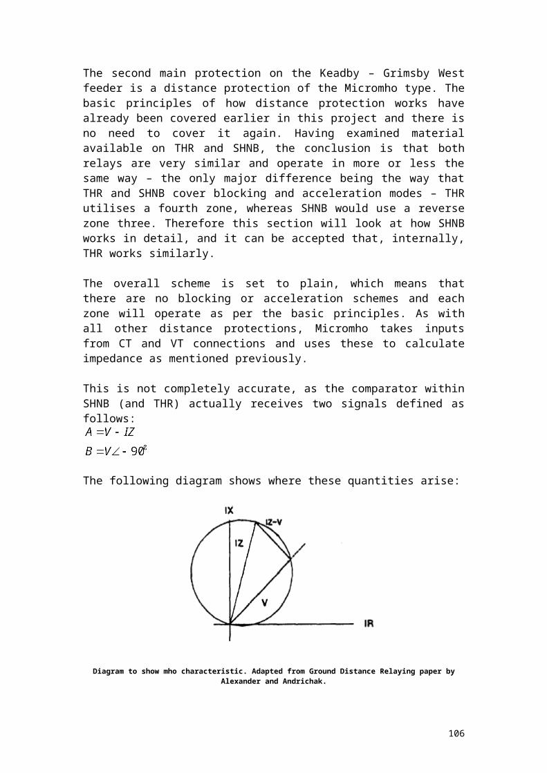
Acknowledgements.
I would like to take this opportunity to thank a number of people who have provided valuable assistance towards completing this project:
My Mentor, Tony Beck, who suggested the three substations done and answered many questions during the project.
My Delivery Engineer, Andy Howcroft, who allowed me to compare projects ‘to keep me on the right track’ and who provided answers to difficult questions.
Paul Wright, who also provided answers to difficult questions pertaining particularly to the protection systems in use at Keadby 400kV and Busbar protection.
The whole of the NE2 Keadby team for providing answers to questions, providing much insight into the history of Keadby 400kV and Grimsby 400kV.
Keith Way at Warwick, for assistance with EDDIS.
John Wilsher and Peter Smith, for their assistance in answering questions and for having the time and patience to read this!
The IS Team, Alan Apsey and Shaun Hughes for assisting me with Livelink access.
Areva T&D, VATech (and Siemens) for sending a catalogue of their products including technical specifications on all their protective relays and systems.
Disclaimer:
I declare that this work is completely my own, with references clearly defined where necessary. Any other similar works unreferenced within are coincidental.
106
Recommended


![Report on Ichchhapore substation Substation...2014/07/06 · Date:02/02/2018 Report on Ichchhapore substation Substation: SubstationEquipment: 1] PowerTransformer: A](https://img.pdfslide.us/doc/110x75/6082a7423c38c8542368e070/report-on-ichchhapore-substation-substation-20140706-date02022018-report.jpg)