Projectile Aerodynamic Jump Due to Lateral Impulsives
by Gene R. Cooper
ARL-TR-3087 September 2003 Approved for public release; distribution is unlimited.

NOTICES
Disclaimers The findings in this report are not to be construed as an official Department of the Army position unless so designated by other authorized documents. Citation of manufacturer’s or trade names does not constitute an official endorsement or approval of the use thereof. Destroy this report when it is no longer needed. Do not return it to the originator.
Army Research Laboratory Aberdeen Proving Ground, MD 21005-5066
ARL-TR-3087 September 2003
Projectile Aerodynamic Jump Due to Lateral Impulsives
Gene R. Cooper
Weapons and Materials Research Directorate, ARL Approved for public release; distribution is unlimited.
ii
Report Documentation Page Form Approved OMB No. 0704-0188
Public reporting burden for this collection of information is estimated to average 1 hour per response, including the time for reviewing instructions, searching existing data sources, gathering and maintaining the data needed, and completing and reviewing the collection information. Send comments regarding this burden estimate or any other aspect of this collection of information, including suggestions for reducing the burden, to Department of Defense, Washington Headquarters Services, Directorate for Information Operations and Reports (0704-0188), 1215 Jefferson Davis Highway, Suite 1204, Arlington, VA 22202-4302. Respondents should be aware that notwithstanding any other provision of law, no person shall be subject to any penalty for failing to comply with a collection of information if it does not display a currently valid OMB control number. PLEASE DO NOT RETURN YOUR FORM TO THE ABOVE ADDRESS. 1. REPORT DATE (DD-MM-YYYY)
September 2003 2. REPORT TYPE
Final 3. DATES COVERED (From - To)
November 2002–October 2003 5a. CONTRACT NUMBER
5b. GRANT NUMBER
4. TITLE AND SUBTITLE
Projectile Aerodynamic Jump Due to Lateral Impulsives
5c. PROGRAM ELEMENT NUMBER
5d. PROJECT NUMBER
1L1622618.H80 5e. TASK NUMBER
6. AUTHOR(S)
Gene R. Cooper
5f. WORK UNIT NUMBER
7. PERFORMING ORGANIZATION NAME(S) AND ADDRESS(ES)
U.S. Army Research Laboratory ATTN: AMSRL-WM-BC Aberdeen Proving Ground, MD 21005-5066
8. PERFORMING ORGANIZATION REPORT NUMBER
ARL-TR-3087
10. SPONSOR/MONITOR'S ACRONYM(S)
9. SPONSORING/MONITORING AGENCY NAME(S) AND ADDRESS(ES)
11. SPONSOR/MONITOR'S REPORT NUMBER(S)
12. DISTRIBUTION/AVAILABILITY STATEMENT
Approved for public release; distribution is unlimited.
13. SUPPLEMENTARY NOTES
14. ABSTRACT
The linear theory for spinning projectiles is extended to account for the application of a simple lateral square impulse activated during free flight. Analytical results are shown to produce simple contributions to the familiar aerodynamic jump formulation. Inquiries regarding jump smearing caused by nonzero impulse length are addressed and answered. The formulation shows for sufficiently long-range target interception; lateral impulse trajectory response for a guided projectile is independent of when the impulse is activated during the yaw cycle. Simple mathematical limits show the presented results reducing to those previously found for a zero-spin projectile acted upon by a singular lateral impulse.
15. SUBJECT TERMS
linear theory, aerodynamic jump, analytic solutions, square impulse
16. SECURITY CLASSIFICATION OF: 19a. NAME OF RESPONSIBLE PERSON Gene R. Cooper
a. REPORT UNCLASSIFIED
b. ABSTRACT UNCLASSIFIED
c. THIS PAGE UNCLASSIFIED
17. LIMITATION OF ABSTRACT
UL
18. NUMBER OF PAGES
32
19b. TELEPHONE NUMBER (Include area code) 410-278-3684
Standard Form 298 (Rev. 8/98) Prescribed by ANSI Std. Z39.18
iii
Contents
List of Figures iv
1. Introduction 1
2. Projectile Dynamic Model 1
3. Projectile Linear Theory 5
4. Projectile Linear Theory Solution 7
5. Pulse Force and Moment Conditions 10
6. Lateral Pulse Smearing 15
7. Lateral Pulse Response Magnitude and Phase Angle 17
8. Target Interception 17
9. Conclusions 20
10. References 21
Appendix A. Flight Coefficients for a 40-mm Projectile 23
List of Symbols 25
Distribution List 27
iv
List of Figures
Figure 1. Projectile position coordinate definition. ........................................................................2 Figure 2. Projectile orientation definition.......................................................................................2 Figure 3. Jump component-j due to lateral impulse vs. impulse duration. ...................................16 Figure 4. Jump component-k due to lateral impulse vs. impulse duration. ..................................16 Figure 5. Magnitude of jump due to lateral impulse vs. impulse duration. ..................................18 Figure 6. Magnitude of jump due to lateral impulse vs. spin rate. ...............................................18 Figure 7. Phase angle of jump due to lateral impulse vs. spin rate...............................................19
1
1. Introduction
The continuing development of microelectromechanical systems is pointing to the possibility of mounting complete sensor systems on medium- and small-caliber projectiles as part of an actively controlled smart munition. Two important technical challenges in achieving this goal are the development of small, rugged sensor suites, and control mechanisms. With regard to the development of control mechanisms, several concepts have emerged that produce controllable impulsive lateral forces on a projectile body. For example, Harkins and Brown (1) considered the use of a set of lateral pulse jets or squibs to reduce dispersion of a rocket by firing squibs to minimize projectile pitch and yaw rate. For the notional cases evaluated, dispersion was reduced by a factor of 5. Jitpraphai and Costello (2) considered the same type of control mechanism and used a trajectory tracking flight control system to improve impact point performance of a direct fire rocket equipped with a ring of squibs. Amitay et al. (3) considered the use of synthetic jet actuators as a control mechanism on lifting bodies. For a spinning projectile incorporating a synthetic jet actuator for control, the synthetic jet actuator is activated over a small portion of a roll cycle leading to a train of lateral pulse forces acting on the projectile near the synthetic jet actuator cavity.
The design of flight control systems for fin-stabilized configurations is well established in the missile community and the control response to force and moment inputs is reasonably well understood. Generally these configurations are treated largely in the same manner as airplanes. While the uncontrolled dynamics of spinning projectiles, both fin stabilized and spin stabilized, have been extensively studied in the ballistics community, issues with regard to control response have received considerably less attention due to the lack of practical application of control technology to spinning projectiles. Using projectile linear theory, this report analytically investigates several aspects of the response of a spinning projectile to lateral pulse forces including swerve response magnitude and phase angle, impulse force smearing, and yaw cycle pulse timing. The report begins with a discussion of the basic projectile dynamic model followed by judicious simplifications to these equations that result in the projectile linear theory equations. The solution of the projectile linear theory equations are used to shed light on intuitive and subtle factors that influence swerve response of a projectile exposed to lateral impulsive loads.
2. Projectile Dynamic Model
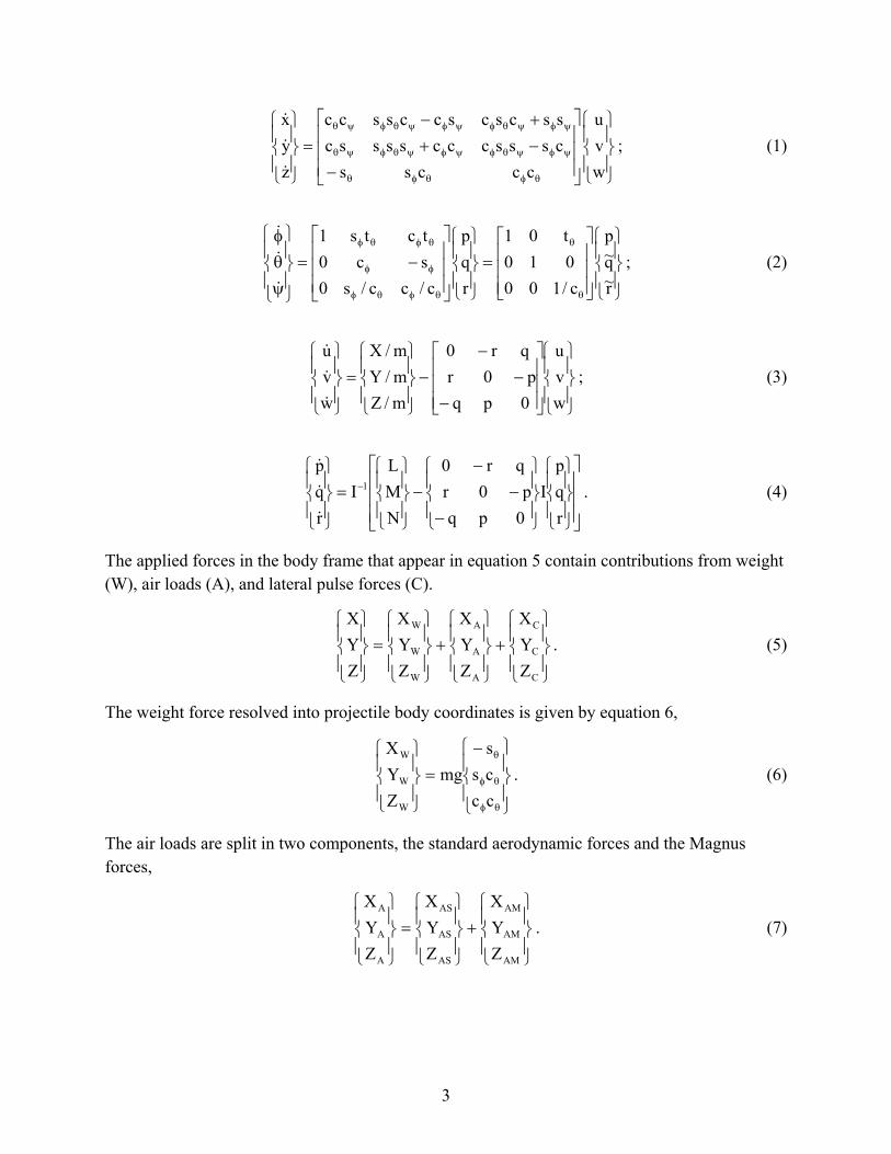
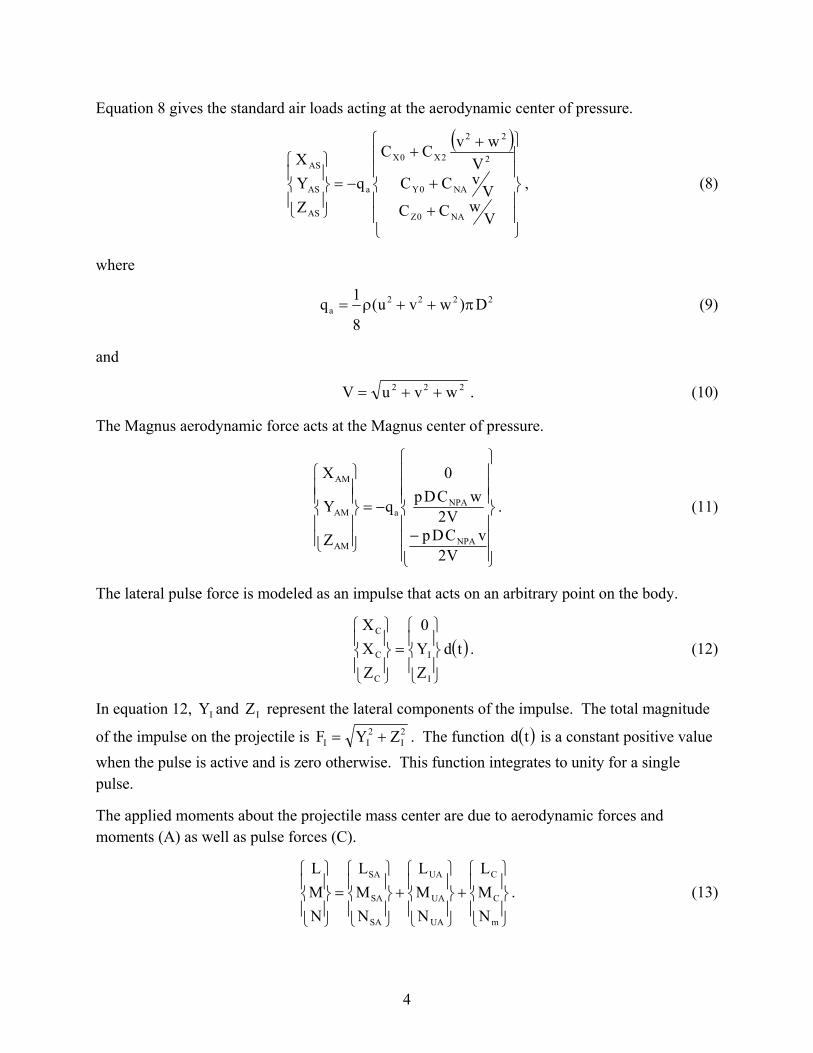
It is well known that the motion of most projectile configurations can be captured using a rigid body 6 degrees of freedom dynamic model (4, 5). The degrees of freedom include three position components of the mass center of the projectile as well as three Euler orientation angles of the
2
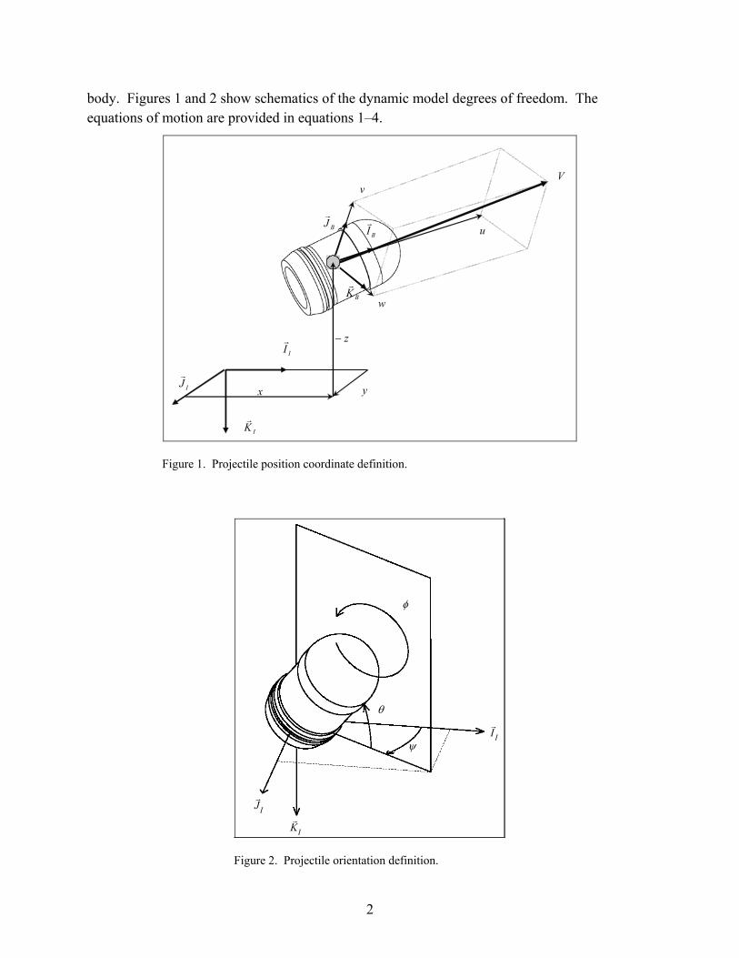
body. Figures 1 and 2 show schematics of the dynamic model degrees of freedom. The equations of motion are provided in equations 1–4.
IIr
IKr
IJr
BKr
BJr
BIr
yx
w
V
u
v
z−
Figure 1. Projectile position coordinate definition.
IIr
ψ
IJr
IKr
φ
θ
Figure 2. Projectile orientation definition.
3
−−++−
=
θφθφθ
ψφψθφψφψθφψθ
ψφψθφψφψθφψθ
wvu
cccsscssscccsssscsscscsccsscc
zyx
&
&
&
; (1)
=
−=
ψθφ
θ
θ
θφθφ
φφ
θφθφ
r~q~p
c/100010t01
rqp
c/cc/s0sc0tcts1
&
&
&
; (2)
−−
−−
=
wvu
0pqp0r
qr0
m/Zm/Ym/X
wvu
&
&
&
; (3)
−−
−−
=
−
rqp
I0pqp0r
qr0
NML
Irqp
1
&
&
&
. (4)
The applied forces in the body frame that appear in equation 5 contain contributions from weight (W), air loads (A), and lateral pulse forces (C).
+
+
=
C
C
C
A
A
A
W
W
W
ZYX
ZYX
ZYX
ZYX
. (5)
The weight force resolved into projectile body coordinates is given by equation 6,
−=
θφ
θφ
θ
cccss
mgZYX
W
W
W
. (6)
The air loads are split in two components, the standard aerodynamic forces and the Magnus forces,
+
=
AM
AM
AM
AS
AS
AS
A
A
A
ZYX
ZYX
ZYX
. (7)
4
Equation 8 gives the standard air loads acting at the aerodynamic center of pressure.
( )
+
+
++
−=
VwCC
VvCCV
wvCC
qZYX
NA0Z
NA0Y
2
22
2X0X
a
AS
AS
AS
, (8)
where
2222a D)wvu(
8
1q π++ρ= (9)
and
222 wvuV ++= . (10)
The Magnus aerodynamic force acts at the Magnus center of pressure.
−
−=
V2vCDp
V2wCDp
0
q
Z
Y
X
NPA
NPAa
AM
AM
AM
. (11)
The lateral pulse force is modeled as an impulse that acts on an arbitrary point on the body.
( )tdZY0
ZXX
I
I
C
C
C
=
. (12)
In equation 12, IY and IZ represent the lateral components of the impulse. The total magnitude
of the impulse on the projectile is 2I
2II ZYF += . The function ( )td is a constant positive value
when the pulse is active and is zero otherwise. This function integrates to unity for a single pulse.
The applied moments about the projectile mass center are due to aerodynamic forces and moments (A) as well as pulse forces (C).
+
+
=
m
C
C
UA
UA
UA
SA
SA
SA
NML
NML
NML
NML
. (13)
5
The aerodynamic moments caused by standard and Magnus air loads are computed with a cross product between the distance vector from the mass center to the force application point and the force itself. An unsteady aerodynamic damping moment is also present, which provides a damping source for angular motion.
+
=
V2DCr
V2DCq
V2pDC
C
DqNML
MQ
MQ
LPDD
a
UA
UA
UA
. (14)
All aerodynamic coefficients and the center of pressures are a function of the Mach number of the projectile mass center. The dynamic model previously described is highly nonlinear due to both three-dimensional rotational kinematics expressions and the presence of complex aerodynamic forces. The applicability of the equations of motion previously shown, have been validated over the past 60 years at aeroballistic ranges throughout the world (5).
3. Projectile Linear Theory
Pressed with the need to predict the trajectory and stability of a ballistic shell so that useful performance data could be generated with primitive computers, early ballisticians vigorously investigated mathematical simplifications to the equations of motion of a projectile. What emerged over time was a set of simplified and solvable, yet accurate, linear differential equations, which today is commonly termed “projectile linear theory.”
The governing equations developed previously are expressed in the body reference frame. In projectile linear theory, the lateral translational and rotational velocity components are transformed to a nonrolling reference frame. The nonrolling frame or so-called fixed plane frame proceeds with only precession and nutation rotations from an inertial reference frame. Components of linear and angular body velocities in the fixed plane frame can be computed from the body frame components of the same vector through a single-axis rotational transformation. For example, the body frame components of the projectile mass center velocity are transformed to the fixed plane frame by
φφ−
φφ=
w
v
u
cossin0
sincos0
001
w~v~u~
. (15)
6
It should be noted that the ~ superscript indicates the vector components are described in the fixed plane reference frame. In projectile linear theory, a change of variables from station line velocity component, u , to total velocity, V , is performed. Equations 16 and 17 relate V and u and their derivatives.
222222 w~v~uwvuV ++=++= ; (16)
V
dtw~dw~
dtv~dv~
dtduu
Vdtdww
dtdvv
dtduu
dtdV ++
=++
= . (17)
A change of variables from time, t , to dimensionless arc length, s , is also made. Equation 18, as defined by Murphy (4), gives the dimensionless arc length,
dtVD1s
t
0∫= . (18)
Equations 19 and 20 relate time and arc length derivatives of a given quantity ζ . Dotted terms refer to time derivatives, and primed terms denote dimensionless arc length derivatives.
ζ′
=ζ
VD& , (19)
ζ′
′+ζ ′′
=ζ
VV
VD 2
&& . (20)
In projectile linear theory, several assumptions regarding the relative size of different quantities are made to simplify the analysis. Euler yaw and pitch angles are small so that: θθ ≈)sin( ,
1)cos( ≈θ , ψ≈ψ)sin( , and 1)cos( ≈ψ and the aerodynamic angle of attack is small so that Vw~=α and Vv~=β . The projectile is mass balanced such that 0III YZXZXY === and
YZZYYYYZZ IIIII ≡=⇒= . The projectile is aerodynamically symmetric such that 0CC 0Z0Y == . Quantities V and φ are large compared to v,r,q,ψ,θ, and w , such that
products of small quantities and their derivatives are negligible. Application of these assumptions results in equations 21–29.
Dx =′ ; (21)
ψ+=′ Dv~VDy ; (22)
θ−=′ Dw~VDz ; (23)
7
pVD
=φ′ ; (24)
q~VD
=θ′ ; (25)
r~VD
=ψ′ ; (26)
VDgVm2
SDCV XO θ−
ρ−=′ ; (27)
pI4
CDSVI2CDSp
X
LP3
X
LDD2 ρ
+ρ
=′ ; (28)
+
+
−
−−
−−
=
′′′′
I
I
I
I
NM
GZY
r~q~w~v~
EFDB
DC
FEDC
DB
0DA0D00A
r~q~w~v~
; (29)
( )
( )
−
−
=
0y
x
y
MQ5
y
CGCOPNA4
0y
CGMAGYPA5
NA3
VIIDpI16CDρπ
I8SLSLCDρπ
VI16SLSLCDpρπ
m8CDρπ
FECBA
. (30)
These equations are a coupled set of linear differential equations except for the fact that the total velocity, V , appears in the coefficients of many of the dynamic equations.
4. Projectile Linear Theory Solution
Linear theory offers physical insight into the projectile flight dynamics because closed form solutions can be readily obtained (4). Using the assumption that V changes slowly with respect
8
to the other variables, it is thus considered to be constant, 0VV ≈ , when it appears as a coefficient in all dynamic equations except its own. Moreover, pitch attitude of the projectile is regarded as constant in the velocity equation, uncoupling the velocity equation from the system. The angle-of-attack dynamics or epicyclic motion in equation 29, together with the roll dynamics in equation 28 are uncoupled and form a linear system of differential equations. In projectile linear theory, the Magnus force in equations 25 and 26 is typically regarded as small in comparison to the other aerodynamic forces and is shown only for completeness. In further manipulation of the equations, all Magnus forces will be dropped. Magnus moments will be retained however, due to the magnitude amplification resulting from the cross product between Magnus force and its respective moment arm.
The solution to the differential equation equation 27, for the forward velocity, is
( )
−+=
−−1ea
beVsVsa2
V
Vsa220
VV , (31)
where
m2CDSa 0X
Vρ
= (32)
and
0V Dgb θ= . (33)
When 00 =θ , the velocity solution reduces to the familiar exponential decay form (4).
The roll dynamic equation is a nonhomogeneous linear differential equation with the following solution:
( ) 0p
psb0
p
p0 V
ba
e Vba
psp p −
+= , (34)
where
XX
LDD2
p I2CDSa ρ
= (35)
and
XX
LP3
p I4CDSb ρ
= . (36)
9
In order to develop the swerve closed form solution, the epicyclic equations must first be solved because the lateral translation and rotational velocity components are contained in the attitude differential equations, and the attitudes are contained within the swerve differential equations.
The epicyclic differential equations consist of a set of four coupled nonhomogeneous differential equations. The homogeneous solution is easily formed using the free vibration modes and mode shapes, and the results are given by the intrinsic complex expression,
( ) ( ) ( )( )
( ) ( ) ( )( )
++−+−+±−−
++++−+±+−=
B2FAEi2C4FAEFiAE
B2FAEi2C4FAEFiAE
s
s
s
s
222
22
s
f
s
f
. (37)
The sum and product of fs and ss give the relations found in the next expression,
( ) ( )
Φλ+Φλ−λλ−ΦΦΦ+Φλ+λ
=
+−+
−
fssf
sfsf
sf
sf
BFACEAFAE
. (38)
Two more simplifications based on size are introduced. First, neglect the product of damping and secondly, the product EA is neglected because the density ratio is assumed small. A solution may now be obtained for both the fast and the slow damping factors and turning rates for the translational and rotational velocities.
−
+
−−
+
−−
=λEAF
B2FA21
C4F
F12
EA
2f; (39)
−+=Φ C4FF2
1 2f
; (40)
−
+
−−
−
−−
=λEAF
B2FA21
C4F
F12
EA
2s; (41)
10
−−=Φ C4FF2
1 2s
. (42)
5. Pulse Force and Moment Conditions
The pulse force applied to the projectile is taken to be a lateral impulsive force, and this force is due to an actuator attached to the projectile body (equation 29). For this investigation, the force actuator is modeled as a scaled square wave pulse so that the resulting force and moment components in the nonrolling frame are as follows:
n
B0
nnn0
I L2
sVpDcosLsssgnsssgnVF
Y
φ+
−−−
−
=
∗
; (43)
n
B0
nnn0
I L2
sVpDsinLsssgnsssgnVF
Z
φ+
−−−
−
=
∗
; (44)
n
B0
nnn0
I LD2
sVpDsinLsssgnsssgnVM
M
φ+
−−−
−
−=
∗
; (45)
n
B0
nnn0
I LD2
sVpDcosLsssgnsssgnVM
N
φ+
−−−
−
=
∗
, (46)
for a square wave pulse of length nL that is initiated at ns represented as
2
0
d
Vm
FDF =∗
(47)
and
11
20y
rd2
VI
XFDM =∗
. (48)
Note that the last two expressions become equivalent to delta function impulses in the limit of 0Ln → .
Once the simplified mode shapes of equation 29 are obtained, the initial conditions for r~ and ,q~ ,w~ ,v~ are used to complete the solution. Equations 49 and 50 are the analytical solutions
for the fixed plane translation velocities v~ and w~ , expressed in phase-amplitude form.
( )
( ) ( ) ( )
( ) ( ) ; 2
1LsssgnφF
2LsssgnsssgnφF
sΦ,sΦF
)Θssin(ΦeV)Θscos(ΦeV(s)v~
nnB3
nnnB2
sf1
V2Ssλ
2V1Fsλ
1sf
+−−
+
−−−−
+
+
−+−=
(49)
( ) ( )
( ) , 2
1Lsssgn2πφF
2Lsssgnsssgn
2πφF
2πsΦ,
2πsΦF
)Θscos(ΦeV)Θssin(ΦeV(s)w~
nnB3
nnnB2
sf1
V2Ssλ
2V1Fsλ
1sf
+−−
−+
−−−−
−+
−−+
−−−=
(50)
where
2
fsf
00f0f
2
fsf
00f0ff
1
Dr~Ev~Fw~Dq~Ew~v~FV
Φ−ΦΦ
−−
Φ−Φ
+
Φ−ΦΦ
−Φ+Φ
Φ−
= (51)
12
2
fss
00s0s
2
sss
00s0ss
2
Dr~Ev~Fw~Dq~Ew~v~FV
Φ−ΦΦ
−−
Φ−Φ
+
Φ−ΦΦ
−Φ+Φ
Φ−
= ; (52)
−Φ+Φ
Φ−
−−
Φ−Φ
=Θ−
Dq~Ew~v~F
Dr~Ev~Fw~
tan00f0ff
00f0f1
1V ; (53)
−−
Φ−Φ
−Φ+Φ
Φ−
=Θ−
Dr~Ev~Fw~
Dq~Ew~v~Ftan
00s0s
00s0ss1
2V ; (54)
( )
( )( ) ( )
( ) ( )( )( )
( )( ) ( )
( ) ( )( )( )
;ΦΦ
FG
ΦΦPΦΦsΦsinEPΦ
sΦcosPΦΦFPΦeG
ΦΦΦPΦsΦsinEΦP
sΦcosΦPΦFΦPeG
sΦ,sΦF
sf
fsss
ss
ss2sssλ
fsff
ff
f2fffsλ
sf1
s
f
−
−−
−+
+−−
−
−−
−+
+−−
=
(55)
13
( )( ) ( ) ( )[ ]
( )( )
( ) ( ) ( )[ ]( )( )
( ) ( ) ( ) ( )[ ]( )( ) ;
LΦPΦPφsPcos FEMφsPsinFPFV
LΦPΦΦcosΩ FEMsinΩFFΦeV
LΦPΦΦcosΩ FEMsinΩFFΦeVφF
nsf
BB0
nsfs
ssfssλ
0
nffs
fffssλ
0B2
ns
nf
−−++++−
+
−−++−
−
−−++−
=
∗∗∗
∗∗∗−
∗∗∗−
(56)
( )
( )( ) ( )( )
( ) ( )( )( )
( )( ) ( )( )
( ) ( )( )( ) ;
LΦPΦΦcos∆ FEMsin∆FΦF
sinΩFΦFcosΩFEMeeV
LΦPΦΦcos∆ FEMsin∆FΦF
sinΩFFΦcosΩFEMeeV
φF
nsfs
fff
sssLλ
sLsλ0
nffs
fff
fffLλ
sLsλ0
B3
ns
nns
nf
nnf
−−
+−−−
−++
−
−−
+−−−
−++
=
∗∗∗
∗∗∗
−−
∗∗∗
∗∗∗
−−
(57)
0VpDP = ; (58)
ssP,ssP sBnssfBnff Φ−φ−
Φ−−=ΩΦ+φ+
Φ−=Ω ; (59)
snfsfnff LP,LP Ω−
Φ−=∆Ω+
Φ−=∆ . (60)
Swerving motion is measured along the earth-fixed IJ and IK axes. To an observer standing behind the gun tube, these axes are oriented such that positive IJ is to the right and positive IK is pointed downward. The swerving motion results from a combination of the normal aerodynamic forces, as the projectile pitches and yaws, plus the forces and moments due to the applied impulse. Differentiating equations 22 and 23 with respect to nondimensional arc length, generates the swerve equations such that
14
0n
Bnnn
Vv~A
L2
pscosLsssgnsssgnF
Dy
−
φ+
−−−
−
=
″
∗
(61)
and
( ) ( )( ) ( )
0n
Bnnn
V
w~AG
L2
pssinLsssgnsssgnF
D
z −+
φ+−−−−=
″
∗
. (62)
Integrating these equations is straightforward, but the solutions are judged to be too long to be listed here. However, the asymptotic limit of these solutions, ∞→s , is of special interest. For a stable projectile, the swerve caused by epicyclical vibration decays as the projectile progresses downrange and does not affect the long-term lateral motion of the projectile. When a lateral pulse is applied to the projectile at arc length ns , its effect on the target impact point is predominantly due to induced jump, provided the target distance is sufficient to allow the transients to decay. Projectile linear theory shows that the long-term center of mass solution, or swerve, contains terms that remain bounded with arc length s plus terms that are linear with s , and if gravity is included the solution will have even higher order diverging terms. These higher order terms are typically denoted as gravity drop. The linear terms are called jump terms, which are caused by initial conditions at the gun muzzle, lateral pulse forces, and aerodynamic characteristics. Mathematically, setting gravity to zero and subsequently evaluating the following limits formally defines total jump.
Ks
Js
ΓsD
z(s) and,ΓsD
y(s) limlim ==∞→∞→
. (63)
The total jump vector Γ is expressed as the sum of two vectors. The first vector represents the jump attributable to muzzle conditions, and the lateral pulse is represented by the second, thus resulting in the following expression:
( ) ( )
Π
ΠΛ+
−−
−+
++
−−+
+++
−=
Γ
Γ
sin
cos
DrEvFw
DqEwFv
BFACEA
CEABFA
VCEABFA
A
000
000
0
22K
J , (64)
for which
15
( ) ( )( ) ( )
( ) ( )( ) ( )
( ) ( ) 0,LasφsPYZtanφsP2LPYZtanΠ
,CEABFA
MCEAAFBCECAFBAZ
,CEABFA
FFCEBAMBFAAY
nBn1
Bnn1
22
22
22
→−−→−−−=
++++−+++
=
+++−++
=
−−
∗∗
∗∗
and
( )( ) 0.LasZY
2LP2LPsinZYΛ n
22
n
n22 →+→+= (65)
The quantities Λ and Π are the magnitude and phase angle of the jump vector attributed to the lateral pulse. It is interesting to note that the jump terms induced by the lateral pulse are not dependent on the lateral state of the projectile ( ) ( ) ( ) ( )( )sr~ and ,sq~,sw~,sv~ , thus this particular contribution to jump is not coupled to the projectile’s angle of attack. Equation 65 extends the work by Guidos and Cooper (6) who considered nonspinning projectiles subject to a singular
delta function impulse. Limiting 0P,Ln →
in equations 64 and 65 produces expressions
that agree with their previous predictions.
6. Lateral Pulse Smearing
In order to better understand the swerve response due to a lateral pulse, results for a representative spin-stabilized 40-mm projectile configuration are calculated and discussed in this and the next two sections. Nominal values for the aerodynamic coefficients, the projectile physical parameters, and flight characteristics are given in the Appendix. All results presented use these values unless specified differently. Diversions from these nominal values are clear from the context of the particular chart under examination.
Plots showing the effect of smearing are given in Figures 3 and 4 for the applied force 510 3.838F −∗ ×= and moment arms
+→−= 635.0 to 635.0DXr . Negative values of rX
indicate that the application point of the pulse force is aft of the mass center while positive values indicate the pulse force is forward of the mass center. To illustrate the smearing effects, the roll position, Nφ , of the lateral impulse force is assumed to act primarily along the nonrolling Y-axis. This means the arc length, Ns , corresponding to the center of the pulse satisfies the
16
-20
0
20
40
60
80
0 20 40 60 80 100 120 140Ln
Λ C
os Π
x 1
0 6
Xr/D = +0.635
Xr/D = +0.318
Xr/D = 0.0
Xr/D = -0.318
Xr/D = -0.635
N2YZtan&10838.3F15
π=Π−×=−∗
Figure 3. Jump component-j due to lateral impulse vs. impulse duration.
-1.5
-1.0
-0.5
0.0
0.5
0 20 40 60 80 100 120 140
Ln
Λ S
in Π
x 1
0 6
Xr/D = +0.635
Xr/D = +0.318Xr/D = +0.0
Xr/D = -0.318
Xr/D = -0.635
N2YZtan&10838.3F15
π=Π−×=−∗
Figure 4. Jump component-k due to lateral impulse vs. impulse duration.
17
expression L2,1,0N,N2s BNN =π=φ+φ′=φ . To ensure this force is acting nominally along the nonrolling Y-axis, the activation point begins at 2Lss nNn −= so that the duration of the impulse brackets N2N π=φ . Increasing pulse length, nL , causes the jump components to cyclically decay while its value at 0Ln = corresponds to a lateral impulse that is proportional to the delta function ( )nss −δ . Values of nL where the jump is zero represent situations where the duration of the lateral pulse coincides with a roll cycle. This accounts for the post multiplier,
0
n
V2DLpsin , in equation 65 having π2 zero crossings and causes the cyclical jump results in
Figures 3 and 4. Notice for the cases presented the response due to a pulse in the IJ direction is predominantly along IJ ; however, a smaller out-of-phase component of swerve is also generated.
7. Lateral Pulse Response Magnitude and Phase Angle
Figure 5 has charts showing the absolute value of Λ as a function of the pulse length nL for the
previous parameter values 5
10838.3F−∗
×= and
+→−= 635.0 to 635.0DXr . Here again
the impulse is assumed to bracket N2N π=φ . The maximum value occurs at 0Ln = , which is the delta function result, as is justified from equation 65. Consideration of Λ as a function of
spin rate p is displayed in Figure 6 for several pulse durations
→= 40to0Ln . This figure
shows that the rate at which the aerodynamic jump magnitude decreases, with spin rate, is strongly dependent on the pulse duration. Again, this is attributed to cancellation (i.e., smearing) effects, which become more pronounced with increasing values of nL .
Figure 7 gives the phase angle, Π , (equation 65) as a function of spin rate for the same values of the moment arm length DXr previously discussed. Notice that the phase angle linearly increases with spin rate, indicating that spin-stabilized projectiles are most susceptible to an out-of-phase swerve response due to lateral pulse forces.
8. Target Interception
The last topic discussed in this report examines the relationship between a given change in
aerodynamic jump,
Γ∆Γ∆
K
J , and the impulse needed to create this change. This may be desirable
18
0
20
40
60
80
0 20 40 60 80 100 120 140Ln
Mag
nitu
de
Λ x
10
6
Xr/D = +0.635
Xr/D = +0.318
Xr/D = 0.0
Xr/D = -0.318
Xr/D = -0.635
N2YZtan&10838.3F15
π=Π−×=−∗
Figure 5. Magnitude of jump due to lateral impulse vs. impulse duration.
0
5
10
15
20
25
0 100 200 300 400 500 600
Spin Rate p (1/sec.)
Jum
p M
agni
tude
Λ
x 1
0 6 Ln = 0
Ln = 10Ln =
Ln = 30Ln = 40
Spin Rate p (1/s)
N2YZtan&10838.3F15
π=Π−×=−∗
Figure 6. Magnitude of jump due to lateral impulse vs. spin rate.
19
-3
-2
-1
0
1
0 100 200 300 400 500 600
Spin Rate p (1/sec.)
Phas
e A
ngle
Π (D
egre
es)
Xr/D = -0.636
Xr/D = -0.318Xr/D = 0.0
Xr/D = +0.635
Xr/D = +0.318
N2YZtan&10838.3F15
π=Π−×=−∗
Spin Rate p (1/s)
Figure 7. Phase angle of jump due to lateral impulse vs. spin rate.
when the activated impulse is strong enough to force a projectile to strike its target, located at a
relative position
Γ∆Γ∆
K
J , with a single impulse. Hence, equation 64 requires
ΠΠΛ=
Γ∆Γ∆
cossin
K
J . (66)
Solving this system for Π and insisting that Π remains real valued yields the following two equations for target interception:
( )
Σ+Σ
Γ∆+Γ∆=
2
K
2
J0
KJn
0
n2
V2
sDpV2sDpsin , (67)
and
N2tanV2LDp
VsDp
KKJJ
KJJK1
0
nB
0
n π+
ΣΓ∆+ΣΓ∆ΣΓ∆−ΣΓ∆
+−=φ+ − . (68)
20
Using equation 65, the impulse force IF can be determined from equation 67, for a given moment arm rX , and then equation 68 solved for Bφ will guarantee target impact, provided the
relative target position,
Γ∆Γ∆
K
J , is known.
9. Conclusions
An analytical approach for quantifying the effect of a lateral square impulse disturbing a projectile during free flight has been presented. All of the analysis was based on projectile linear theory, which produces simple closed form solutions for the assumed square pulse disturbance. These solutions are then used to calculate the projectile swerving motion, so that the long-term effects of the lateral impulse are readily determined. The primary interest regarding target interception is the projectile’s aerodynamic jump. Changes to aerodynamic jump caused by the lateral impulse forces were shown to produce easy-to-understand additive contributions to the usual aerodynamic jump of a free-flight projectile with no applied impulse.
The important question concerning smearing effects originating from a finite length pulse has been addressed where pulse-induced control authority is shown to diminish as nL1 . Calculations also show the additional aerodynamic jump magnitude, Σ , decreases with spin rate p when subjected to various pulse lengths nL .
21
10. References
1. Harkins, T. E.; Brown, T. G. Using Active Damping as a Precision-Enhancing Technology for 2.75-Inch Rockets; ARL-TR-1772; U.S. Army Research Laboratory: Aberdeen Proving Ground, MD, 1999.
2. Jitpraphai, T.; Costello, M. Dispersion Reduction of a Direct Fire Rocket Using Lateral Pulse Jets. Journal of Spacecraft and Rockets 2001, 38 (6), 929–936.
3. Amitay, M.; Smith, D.; Kibens, V.; Parekh, D.; Glezer, A. Aerodynamic Flow Control Over an Unconventional Airfoil Using Synthetic Jet Actuators. AIAA Journal 2001, 39 (3), 361–370.
4. Murphy, C. H. Free Flight Motion of Symmetric Missiles; BRL-TR-1216; U.S. Army Ballistic Research Laboratories: Aberdeen Proving Ground, MD, 1963.
5. McCoy, R. L. Modern Exterior Ballistics: the Launch and Flight Dynamics of Symmetric Projectiles; Schiffer Publishing Ltd.: Atglen, PA, 1999.
6. Guidos, B.; Cooper, G. Linearized Motion of a Fin-Stabilized Projectile Subjected to a Lateral Impulse. Journal of Spacecraft and Rockets 2002, 39 (3).

22
INTENTIONALLY LEFT BLANK.
23
Appendix A. Flight Coefficients for a 40-mm Projectile
The numerical values used for the graphical presentations given in this report are shown in the following matrices:
Aerodynamic coefficients:
−
−
−=
800.1
042.0
295.0
329.2
672.2
279.0
C
C
C
C
C
C
MQ
LP
YPA
NA
2X
0X
a .
(A-1)
Physical parameters:
×
×
=
−
−
.ft0713.0
.ft239.0
.ft237.0
.ft137.0
.ftSlug1072.2
.ftSlug1085.2
Slug0116.0
SL
SL
SL
D
I
I
m
25
25
CG
MAG
COP
Y
X
a .
(A-2)
24
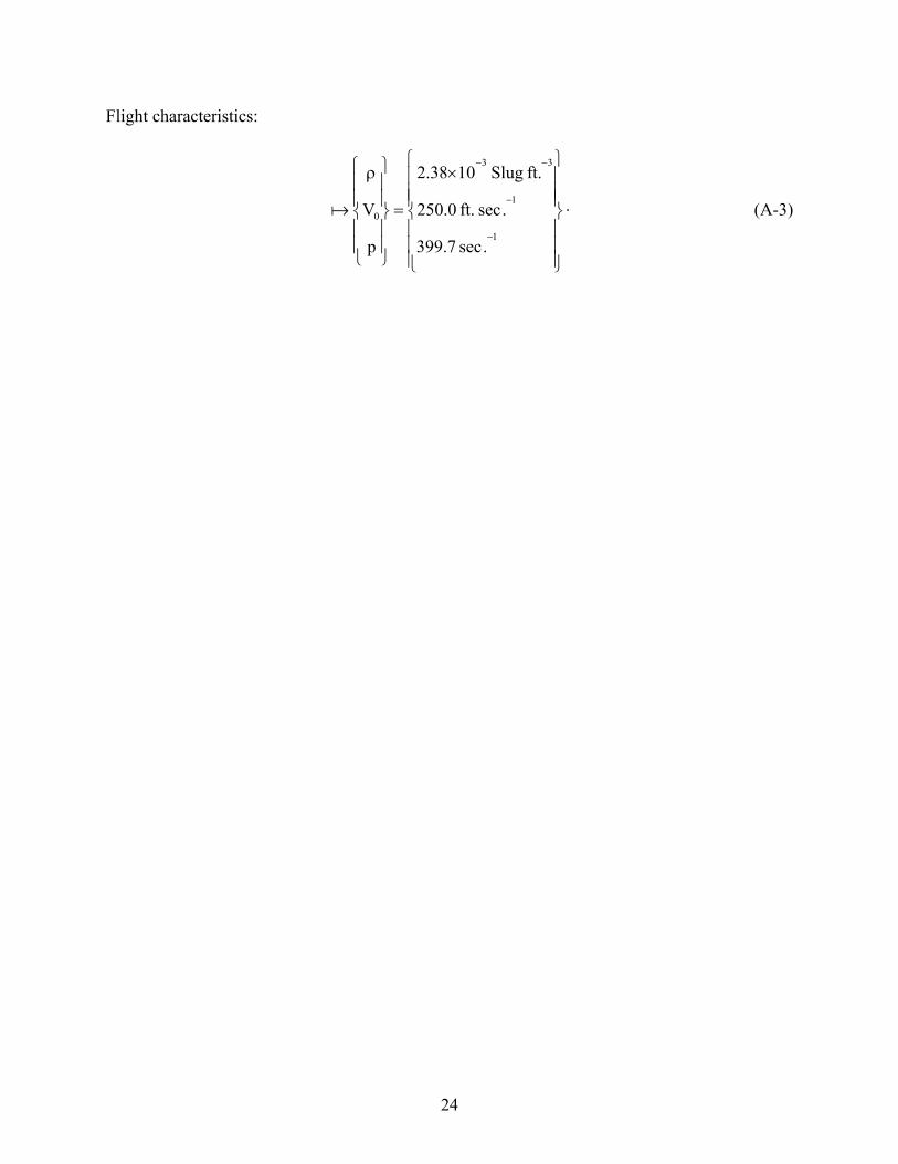
Flight characteristics:
×
=
ρ
−
−
−−
1
1
33
0
.sec7.399
.sec.ft0.250
.ftSlug1038.2
p
Va .
(A-3)
25
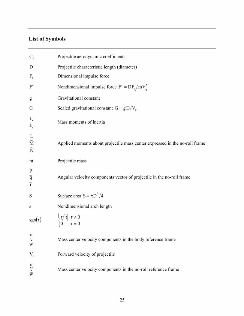
List of Symbols
iC Projectile aerodynamic coefficients
D Projectile characteristic length (diameter)
dF Dimensional impulse force
∗F Nondimensional impulse force 2
0d VmFDF =∗
g Gravitational constant
G Scaled gravitational constant 0VDgG =
Y
X
II
Mass moments of inertia
N~M~L
Applied moments about projectile mass center expressed in the no-roll frame
m Projectile mass
r~q~p
Angular velocity components vector of projectile in the no-roll frame
S Surface area 4DS2
π=
s Nondimensional arch length
( )τsgn
=τ≠τττ
000
wvu
Mass center velocity components in the body reference frame
0V Forward velocity of projectile
w~v~u
Mass center velocity components in the no-roll reference frame
26
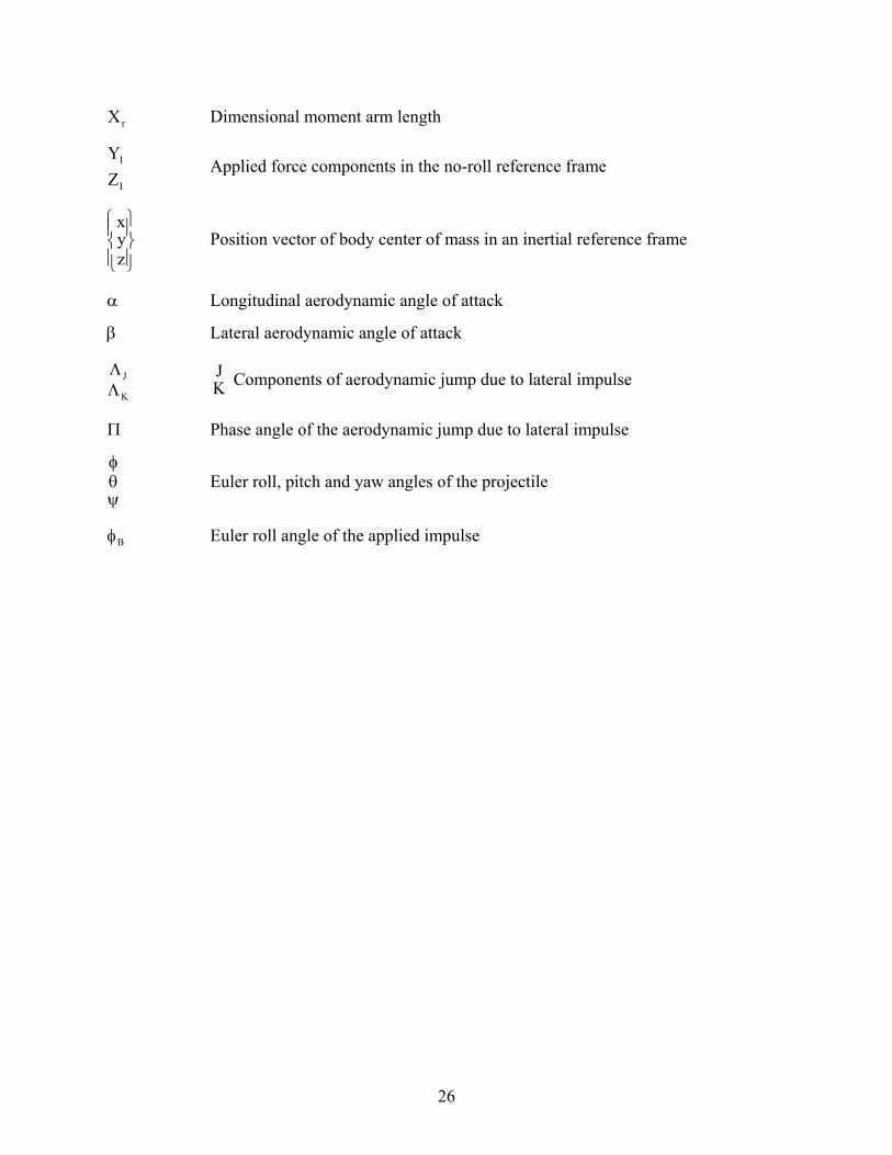
rX Dimensional moment arm length
I
I
ZY
Applied force components in the no-roll reference frame
zyx
Position vector of body center of mass in an inertial reference frame
α Longitudinal aerodynamic angle of attack
β Lateral aerodynamic angle of attack
K
JΛΛ K
J Components of aerodynamic jump due to lateral impulse
Π Phase angle of the aerodynamic jump due to lateral impulse
ψθφ
Euler roll, pitch and yaw angles of the projectile
Bφ Euler roll angle of the applied impulse
NO. OF NO. OF COPIES ORGANIZATION COPIES ORGANIZATION
27
2 DEFENSE TECHNICAL INFORMATION CENTER DTIC OCA 8725 JOHN J KINGMAN RD STE 0944 FT BELVOIR VA 22060-6218 1 COMMANDING GENERAL US ARMY MATERIEL CMD AMCRDA TF 5001 EISENHOWER AVE ALEXANDRIA VA 22333-0001 1 INST FOR ADVNCD TCHNLGY THE UNIV OF TEXAS AT AUSTIN 3925 W BRAKER LN STE 400 AUSTIN TX 78759-5316 1 US MILITARY ACADEMY MATH SCI CTR EXCELLENCE MADN MATH THAYER HALL WEST POINT NY 10996-1786 1 DIRECTOR US ARMY RESEARCH LAB AMSRL D DR D SMITH 2800 POWDER MILL RD ADELPHI MD 20783-1197 1 DIRECTOR US ARMY RESEARCH LAB AMSRL CS IS R 2800 POWDER MILL RD ADELPHI MD 20783-1197 3 DIRECTOR US ARMY RESEARCH LAB AMSRL CI OK TL 2800 POWDER MILL RD ADELPHI MD 20783-1197 3 DIRECTOR US ARMY RESEARCH LAB AMSRL CS IS T 2800 POWDER MILL RD ADELPHI MD 20783-1197
ABERDEEN PROVING GROUND 2 DIR USARL AMSRL CI LP (BLDG 305) AMSRL CI OK TP (BLDG 4600)

NO. OF NO. OF COPIES ORGANIZATION COPIES ORGANIZATION
28
8 PROJECT MANAGER TANK MAIN ARMAMENT SYS SFAE GCSS TMA R MORRIS C KIMKER E KOPACZ R DARCY D GUZIEWICZ P CARDELL C CORDING R MCDANOLDS PICATINNY ARSENAL NJ 07806-5000 1 COMMANDER US ARMY TACOM ARDEC SFAE GCSS ARMS R KOWALSKI PICATINNY ARSENAL NJ 07806-5000 1 COMMANDER US ARMY TACOM ARDEC AMSTA AR FSA P P MAGNOTTI PICATINNY ARSENAL NJ 07806-5000 1 COMMANDER US ARMY TACOM ARDEC AMSTA DSA MO J TERHUNE PICATINNY ARSENAL NJ 07806-5000 1 COMMANDER US ARMY TACOM ARDEC AMSTA AR FSP G R NIXON PICATINNY ARSENAL NJ 07806-5000 1 COMMANDER US ARMY TACOM ARDEC SFAE GCSS CR R BILLINGTON PICATINNY ARSENAL NJ 07806-5000
3 COMMANDER US ARMY TACOM ARDEC AMSTA AR CCH A R CARR M LUCIANO A MUSALLI PICATINNY ARSENAL NJ 07806-5000 2 COMMANDER US ARMY TACOM ARDEC AMSTA AR CCL B R MAZESKI D AHMAD PICATINNY ARSENAL NJ 07806-5000 2 COMMANDER US ARMY TACOM ARDEC AMSTA AR QAC D RIGOGLIOSO R ROESER PICATINNY ARSENAL NJ 07806-5000 2 COMMANDER US ARMY TACOM ARDEC AMSTA AR CCH A G KOLASA A MOLINA PICATINNY ARSENAL NJ 07806-5000 13 COMMANDER US ARMY TACOM ARDEC AMSTA AR FSF T C LIVECCHIA J GRAU B WONG A FARINA G MALEJKO E VAZQUEZ W TOLEDO L YEE R TROHANOWSKY S HAN W KOENIG H HUDGINS S CHUNG PICATINNY ARSENAL NJ 07806-5000

NO. OF NO. OF COPIES ORGANIZATION COPIES ORGANIZATION
29
3 COMMANDER US ARMY TACOM ARDEC AMSTA AR FSF D K PFLEGER R TESTA E LAROSA PICATINNY ARSENAL NJ 07806-5000 1 COMMANDER US ARMY TACOM ARDEC AMSTA AR FSP I R COLLETT PICATINNY ARSENAL NJ 07806-5000 5 COMMANDER US ARMY TACOM ARDEC AMSTA AR CCH B R SAYER F CHANG G EUSTICE S PATEL G WAGNECZ PICATINNY ARSENAL NJ 07806-5000 7 COMMANDER US ARMY TACOM SFAE GCSS W COL J MORAN LTC S COOPER LTC R GROLLER J NEFF J FLECK S GOODMAN J FLORENCE WARREN MI 48397-5000 1 DIRECTOR US ARMY ARMOR CTR ATZK TD A POMEY FT KNOX KY 40121 1 DIRECTOR US ARMY ARMOR CTR ATZK TS W MEINSHAUSEN FT KNOX KY 40121
2 NGIC J MORGAN J NIX CHARLOTTESVILLE VA 22902 1 DARPA TTO S WALKER 3701 FAIRFAX DR ARLINGTON VA 22203-1714 2 DARPA ATO M MATTICE 3701 FAIRFAX DR ARLINGTON VA 22203-1714 1 COMMANDER US ARMY MICOM AMSMI RD ST T VANDIVER REDSTONE ARSENAL AL 35898-5247 2 DIRECTOR HQ IOC AMSIO SMT W HARRIS M RIVERS ROCK ISLAND IL 61299-6000 3 DIRECTOR BENET LABORATORIES AMSTA AR CCB J VASILAKIS R HASENBEIN G PFLEGL WATERVLIET NY 12189 1 DIRECTOR MARINE CORPS PROGRAMS DEPT NAV SURF WAR CEN DIV CRANE ATTN M OMALLEY 700 AMMUNITION RD FALLBROOK CA 92028-3187
NO. OF COPIES ORGANIZATION
30
6 COMMANDER US ARMY TACOM ARDEC AMSTA AR FSF T R LIESKE J MATTS J WHITESIDE A SOWA F MIRABELLE B TILGHMAN PICATINNY ARSENAL NJ 07806-5000 5 ALLIANT TECHSYSTEMS C AAKHUS R DOHRN J GILES M JANTSCHER K SOENCKSEN 600 2ND ST NE HOPKINS MN 55343-8367 5 ALLIANT TECHSYSTEMS ALLEGANY BALLISTICS LAB W NYGA S OWENS J PARRIL A YURKO D MORRIS 210 STATE RT 956 ROCKET CENTER WV 26726-3548 2 ARROW TECH ASSOC W HATHAWAY R WHYTE 1233 SHELBURNE RD SUITE D 8 PIERSON HOUSE S BURLINGTON VT 05403 2 GENERAL DYNAMICS CORP J BUZZETT F TAN 10101 9TH ST NORTH ST PETERSBURG FL 33702
Recommended