Programmable Serial Interface Card Driver for
NMEA 0183
USER MANUAL
Rev. P1.56
Novebmer 2011
DeltaV is a trademark of Emerson Process Management, Inc © Emerson Process Management, Inc. 1998, 1999.
All rights reserved. Printed in the U.S.A. While this information is presented in good faith and believed to be accurate Mynah Technologies does not
guarantee satisfactory results from reliance upon such information. Nothing contained herein is to be construed as a warranty or guarantee, express or implied, regarding the performance, merchantability, fitness or any other matter with respect to the products, nor as a recommendation to use any product or process in conflict with any patent. Mynah Technologies reserves the right, without notice, to alter or improve the designs or specifications of the products described herein.

Powerful Solutions for Digital Plants
MYNAH Technologies ● 504 Trade Center Blvd. ● Chesterfield, Missouri 63005●Telephone (636) 728-2000 ● Fax (636) 728-2001
www.mynah.com
1
1 INTRODUCTION
1.1 Scope This document is the User Manual for the NMEA 0183 serial communication driver firmware
for the Emerson Process Management (EPM) DeltaV Control System; it provides information required to install, configure, and maintain the driver firmware on the DeltaV Programmable Serial Interface Card (PSIC). The reader should be familiar with EPM’s DeltaV PSIC and connected devices using the NMEA 0183 protocol.
The section Document Format briefly describes the contents of each section of this manual.
System Specifications outlines hardware and software requirements for the Driver firmware.
1.2 Document Format This document is organized as follows:
Introduction Describes the scope and purpose of this document.
Theory of Operation Provides a general functional overview of the NMEA 0183 Driver.
Flashing Firmware Describes flashing procedures for the NMEA 0183 Driver firmware on to the DeltaV PSIC.
Configuration Information Describes procedures and guidelines for configuring the DeltaV PSIC.
Operational Check Provides tips and assistance to ensure PSIC is properly setup and configured.
DeltaV–Field Device Electrical Interface
Describes the electrical interface between DeltaV PSIC and the external Device. Also describes the cable pin assignments for RS232 and RS-422/485 communications.
Technical Support Describes who to call if you need assistance.

Powerful Solutions for Digital Plants
MYNAH Technologies ● 504 Trade Center Blvd. ● Chesterfield, Missouri 63005●Telephone (636) 728-2000 ● Fax (636) 728-2001
www.mynah.com
2
1.3 System Specifications The following table lists the minimum system requirements for the NMEA 0183 Driver: Table 1: System Specifications
Firmware Driver Firmware v1.55 or later
Protocol Compatibility Communications with the external devices are
based on the following document:
The NMEA 0183 Protocol, Compiled by Klaus
Betke, May 2000.
Also Reference the following:
National Marine Electronics Association:
Http://www.nmea.org
Software Requirements DeltaV System Software (Release 6.2 or later) installed on a hardware-appropriate Windows workstation configured as a ProfessionalPlus for DeltaV
Serial Interface Port License (VE4102) if required.
Minimum DeltaV Hardware Requirements
DeltaV Series 2 Serial Module, Hardware Rev 1.1r or later
DeltaV M3, M5, M5+, MD, MD Plus or MX Controller, Power Supply and 8 wide controller carrier

Powerful Solutions for Digital Plants
MYNAH Technologies ● 504 Trade Center Blvd. ● Chesterfield, Missouri 63005●Telephone (636) 728-2000 ● Fax (636) 728-2001
www.mynah.com
3
2 THEORY OF OPERATION
DeltaV comprises an I/O sub-system, in which the PSIC is one type of card. The purpose
of the PSIC is to serially integrate third-party devices, allowing data to be read into and
written out from DeltaV. Each PSIC has 2 communication ports that can be configured as
Master or Slave, using RS-232, RS-485 (Half Duplex), or RS-422 (Full Duplex). Various
communications parameters, such as baud rate, are configurable.
The PSIC can communicate with external devices using RS232, RS485 or RS422.
However, only one external device may be connected to a PSIC port. The Port may be
configured as Master or Slave, and there are 16 datasets available under each port.
In Slave mode, the PSIC only receives NMEA 0183 messages (sentences), parses the
data and stores the values into message specific dataset registers. Datasets must be
configured to match identifiers of expected incoming messages. Messages with
unmatched identifiers are discarded.
In Master mode, the PSIC provides all the Slave functionality. In addition, one or more
datasets may be configured to send NMEA messages out to external devices. Such
messages are considered proprietary. Control Modules in DeltaV are expected to create
the message payload conforming to the NMEA 0183 format (i.e., comma separated
values) and write it into the output dataset. The PSIC driver then takes this message and
appends the NMEA header and checksum to it and sends it out.
Note that this driver is not a general NMEA talker. It only generates a specific
proprietary sentence as described in Sections 4.3.3 and 4.3.4 below.

Powerful Solutions for Digital Plants
MYNAH Technologies ● 504 Trade Center Blvd. ● Chesterfield, Missouri 63005●Telephone (636) 728-2000 ● Fax (636) 728-2001
www.mynah.com
4
3 Flashing the firmware
The driver software distribution contains 8 files. These files must be copied to the DeltaV
directory on your ProPlus Workstation. The path is:
\DeltaV\ctl\ProgSerial\IOD-1196 NMEA 0183
Note that you will have to create this subdirectory. The following shows a completed copy
operation:
After copy completion, you are ready to program (or upgrade) the Programmable Serial
Card with the supplied custom driver software. The steps are as follows:

Powerful Solutions for Digital Plants
MYNAH Technologies ● 504 Trade Center Blvd. ● Chesterfield, Missouri 63005●Telephone (636) 728-2000 ● Fax (636) 728-2001
www.mynah.com
5
1. Click on the Start button and select DeltaV-> Installation-> Controller Upgrade Utility as shown below, and the following dialog will appear:
2. Click on the Upgrade I/O Modules radio button, and then click Next.

Powerful Solutions for Digital Plants
MYNAH Technologies ● 504 Trade Center Blvd. ● Chesterfield, Missouri 63005●Telephone (636) 728-2000 ● Fax (636) 728-2001
www.mynah.com
6
3. The above dialog will appear, listing all the available Controllers in your network. From
this dialog, select the appropriate Controller and then Click Next.
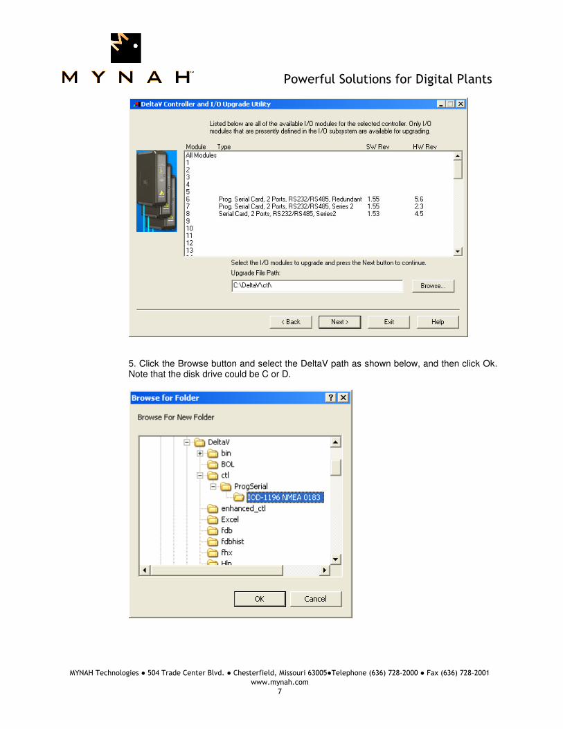
4. The following dialog will appear, listing all the I/O modules in your selected Controller.
The shown list of I/O modules is an example only. Your list will be different. Note: The first time a standard Serial card is upgraded to the NMEA Driver, the
dialog will be as shown below (card 8). When upgrading an existing Programmable Serial Card, skip Steps 5 and 6, and go to Step 7.
Powerful Solutions for Digital Plants
MYNAH Technologies ● 504 Trade Center Blvd. ● Chesterfield, Missouri 63005●Telephone (636) 728-2000 ● Fax (636) 728-2001
www.mynah.com
7
5. Click the Browse button and select the DeltaV path as shown below, and then click Ok.
Note that the disk drive could be C or D.

Powerful Solutions for Digital Plants
MYNAH Technologies ● 504 Trade Center Blvd. ● Chesterfield, Missouri 63005●Telephone (636) 728-2000 ● Fax (636) 728-2001
www.mynah.com
8
6. Select the I/O module again as shown below and then click Next. Go to Step 9.

Powerful Solutions for Digital Plants
MYNAH Technologies ● 504 Trade Center Blvd. ● Chesterfield, Missouri 63005●Telephone (636) 728-2000 ● Fax (636) 728-2001
www.mynah.com
9
7. If you are upgrading an existing Programmable Serial Card, the dialog will be as shown below. From this dialog, select the Programmable Serial Card I/O Module in the list.
For example, we will select I/O Module 8. This will give you a dialog, from which you will
select the file path to where the driver software is located. This path will be: \DeltaV\ctl\ProgSerial\IOD-1196 NMEA 0183 Once you are in the specified directory, you will need to select the following file:
NMEA.S2F
This is shown in the following dialog.

Powerful Solutions for Digital Plants
MYNAH Technologies ● 504 Trade Center Blvd. ● Chesterfield, Missouri 63005●Telephone (636) 728-2000 ● Fax (636) 728-2001
www.mynah.com
10
8. After selecting the .S2F file, Click on Open. This dialog will close and you will be back to the following:

Powerful Solutions for Digital Plants
MYNAH Technologies ● 504 Trade Center Blvd. ● Chesterfield, Missouri 63005●Telephone (636) 728-2000 ● Fax (636) 728-2001
www.mynah.com
11
9. In this dialog, Click Next again. You will get the following dialog, confirming the Controller and I/O Module to program.
Powerful Solutions for Digital Plants
MYNAH Technologies ● 504 Trade Center Blvd. ● Chesterfield, Missouri 63005●Telephone (636) 728-2000 ● Fax (636) 728-2001
www.mynah.com
12
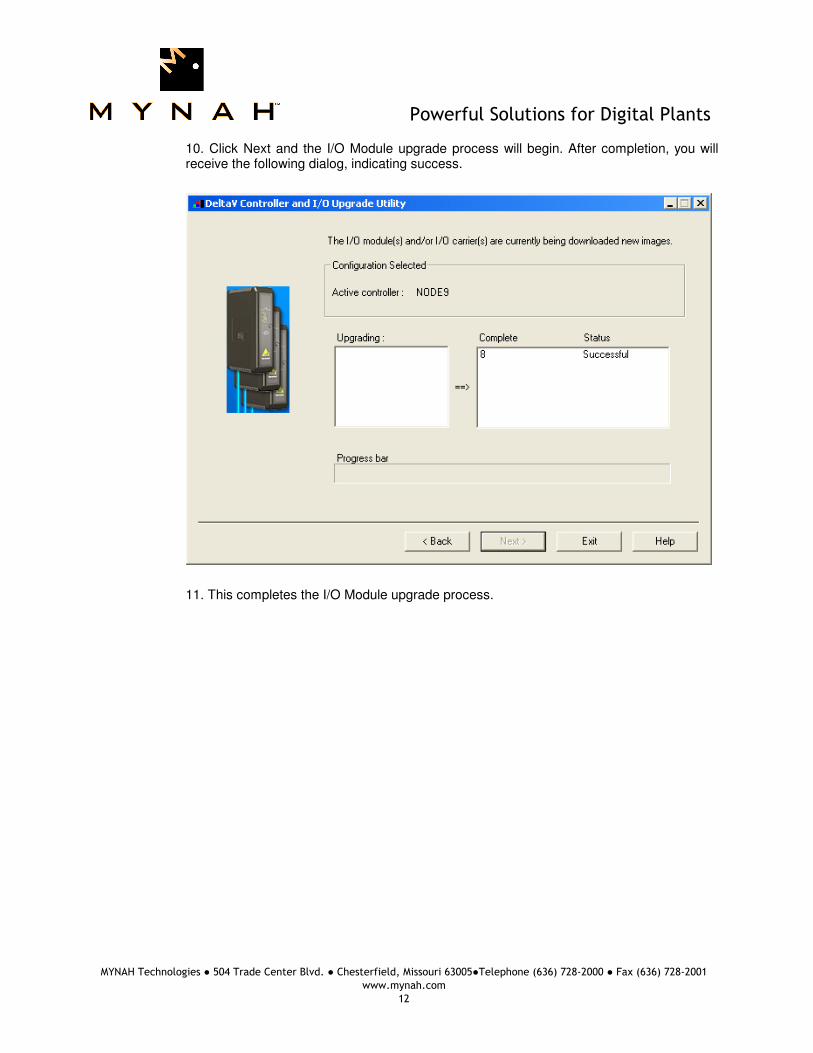
10. Click Next and the I/O Module upgrade process will begin. After completion, you will receive the following dialog, indicating success.
11. This completes the I/O Module upgrade process.

Powerful Solutions for Digital Plants
MYNAH Technologies ● 504 Trade Center Blvd. ● Chesterfield, Missouri 63005●Telephone (636) 728-2000 ● Fax (636) 728-2001
www.mynah.com
13
4 CONFIGURATION INFORMATION
4.1 Port Configuration
First, enable the port. Then click on the Advanced Tab and select Master or Slave. Next, click on the Communications Tab and specify the Port type. Configure the parameters to match the external NMEA 0183 Receiver or Talker device.
4.2 Device Configuration
Specify a device corresponding to the external device. The device address is not used.
4.3 Dataset Configuration
Datasets may be configured as Input or Output. Each input dataset is individually configured to receive a specific NMEA 0182 message. Output datasets are configured in Master mode only to send proprietary messages out to external devices.
4.3.1 Input Dataset Configuration: Configure input datasets as follows: Table 1 - Input Dataset Direction Input
DeltaV Data Type Floating Point w/status
Device Data Type Message ID – see below
Start Address 0
Number of Values 50
Special Data 1 0 or message number
Special Data 2 0
Special Data 3 0
Special Data 4 0
Special Data 5 0

Powerful Solutions for Digital Plants
MYNAH Technologies ● 504 Trade Center Blvd. ● Chesterfield, Missouri 63005●Telephone (636) 728-2000 ● Fax (636) 728-2001
www.mynah.com
14
Specific sentences are supported. These are identified below. Specify the sentence ID in the dataset Device Data Type. Details of data received in each sentence and stored in dataset registers are described in Appendix. Table 2 - Message ID, Name and Description ID Message Name Description 0 N/A Proprietary Message Id, This is used only for Output
Datasets to send a message from DeltaV to external devices.
1 AAM Waypoint Arrival Alarm 2 ALM GPS Almanac Data. This ID comprises more than one
message. A dataset is selected for each expected message. Specify message number in Special Data 1 of the dataset.
3 APA Autopilot Sentence “A” 4 APB Autopilot Sentence “B” 5 BEC Bearing and distance to Waypoint – Dead Reckoning 6 BOD Bearing – Waypoint to Waypoint 7 BWC Bearing and distance to Waypoint – latitude, N/S,
Longitude, E/W, UTC, Status 8 BWR Bearing and distance to Waypoint – Rhumb Line latitude,
N/S, Longitude, E/W, UTC, Status 9 BWW Bearing – Waypoint to Waypoint 10 DBK Depth below Keel 11 DBS Depth below surface 12 DBT Depth below Transducer 13 DPT Heading – Deviation and Variation 14 FSI Frequency Set Information 15 GGA Global Positioning System Fix Data, Time, Position and
fix related data for a GPS receiver 16 GLC Geographic Position, Loran-C 17 GLL Geographic Position – Latitude/Longitude 18 GSA GPS DOP and active satellites 19 GSV Satellites in view. This ID comprises more than one
message. A dataset is selected for each expected message. Specify message number in Special Data 1 of the dataset.
20 GTD Geographic Location in Time Differences 21 HDG Heading – Deviation and Variation 22 HDM Heading – Magnetic 23 HDT Heading – True 24 HSC Heading Steering command 25 LCD Loran-C Signal Data 26 MSK MSK Receiver Interface (for DGPS Beacon Receivers) 27 MTW Water Temperature 28 MWD Weather 29 MWV Wind Speed and Angle 30 OSD Own ship data 31 ROO Waypoints in active route 32 RMA Recommended Minimum Navigation Information
Powerful Solutions for Digital Plants
MYNAH Technologies ● 504 Trade Center Blvd. ● Chesterfield, Missouri 63005●Telephone (636) 728-2000 ● Fax (636) 728-2001
www.mynah.com
15
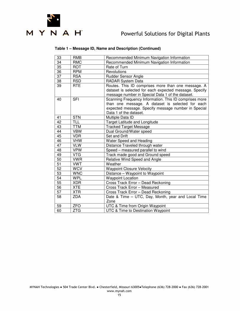
Table 1 – Message ID, Name and Description (Continued)
33 RMB Recommended Minimum Navigation Information 34 RMC Recommended Minimum Navigation Information 35 ROT Rate of Turn 36 RPM Revolutions 37 RSA Rudder Sensor Angle 38 RSD RADAR System Data 39 RTE Routes. This ID comprises more than one message. A
dataset is selected for each expected message. Specify message number in Special Data 1 of the dataset.
40 SFI Scanning Frequency Information. This ID comprises more than one message. A dataset is selected for each expected message. Specify message number in Special Data 1 of the dataset.
41 STN Multiple Data ID 42 TLL Target Latitude and Longitude 43 TTM Tracked Target Message 44 VBW Dual Ground/Water speed 45 VDR Set and Drift 46 VHW Water Speed and Heading 47 VLW Distance Traveled through water 48 VPW Speed – measured parallel to wind 49 VTG Track made good and Ground speed 50 VWR Relative Wind Speed and Angle 51 VWT Weather 52 WCV Waypoint Closure Velocity 53 WNC Distance – Waypoint to Waypoint 54 WPL Waypoint Location 55 XDR Cross Track Error – Dead Reckoning 56 XTE Cross Track Error – Measured 57 XTR Cross Track Error – Dead Reckoning 58 ZDA Date & Time – UTC, Day, Month, year and Local Time
Zone 59 ZFO UTC & Time from Origin Waypoint 60 ZTG UTC & Time to Destination Waypoint

Powerful Solutions for Digital Plants
MYNAH Technologies ● 504 Trade Center Blvd. ● Chesterfield, Missouri 63005●Telephone (636) 728-2000 ● Fax (636) 728-2001
www.mynah.com
16
4.3.2 Input Dataset Example: This is an example of an Input dataset configured to receive the data from a GLL (ID=17) message. Step 1
Step 2

Powerful Solutions for Digital Plants
MYNAH Technologies ● 504 Trade Center Blvd. ● Chesterfield, Missouri 63005●Telephone (636) 728-2000 ● Fax (636) 728-2001
www.mynah.com
17
Step 3

Powerful Solutions for Digital Plants
MYNAH Technologies ● 504 Trade Center Blvd. ● Chesterfield, Missouri 63005●Telephone (636) 728-2000 ● Fax (636) 728-2001
www.mynah.com
18
The GLL message has the following format and information: $GPGLL,1002.00739,N,15957.77057,W,210316.69,A,A*70<0D><0A 1002.00739 Lattitude N N or S – North or South 15957.77057 Longitude W E or W – East or West 210316 Time in UTC format A Status A – Data Valid, V-Data invalid
This data is parsed and stored in dataset registers (shown below in DeltaV Diagnostics). The letters N, W and A are converted to numbers with A=101, B=102, etc. In this example, R2 is 114 indicating N, R4 is 123 indicating W, and R6 is 101 indicating A.

Powerful Solutions for Digital Plants
MYNAH Technologies ● 504 Trade Center Blvd. ● Chesterfield, Missouri 63005●Telephone (636) 728-2000 ● Fax (636) 728-2001
www.mynah.com
19
4.3.3 Output Dataset Configuration: Output datasets may be configured only in Master mode to send proprietary messages to the external device. Configure output datasets as follows: Direction Output
DeltaV Data Type String w/status
Device Data Type 0
Start Address 0
Number of Values 100
Special Data 1 0
Special Data 2 0
Special Data 3 0
Special Data 4 0
Special Data 5 0
4.3.4 Output Dataset Example: Output datasets may be configured only in Master mode. Configure output datasets as follows: Step 1

Powerful Solutions for Digital Plants
MYNAH Technologies ● 504 Trade Center Blvd. ● Chesterfield, Missouri 63005●Telephone (636) 728-2000 ● Fax (636) 728-2001
www.mynah.com
20
Step 2
Step 3
Powerful Solutions for Digital Plants
MYNAH Technologies ● 504 Trade Center Blvd. ● Chesterfield, Missouri 63005●Telephone (636) 728-2000 ● Fax (636) 728-2001
www.mynah.com
21
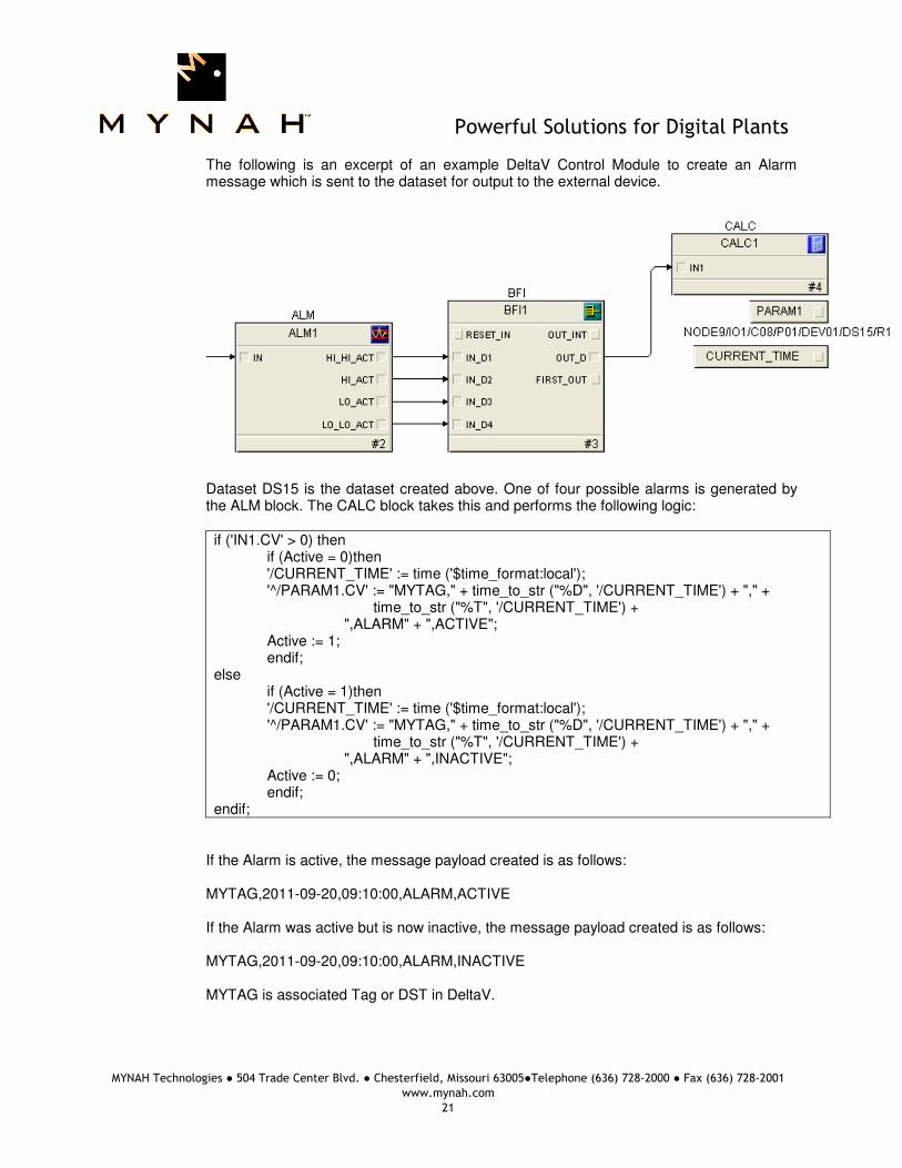
The following is an excerpt of an example DeltaV Control Module to create an Alarm message which is sent to the dataset for output to the external device.
Dataset DS15 is the dataset created above. One of four possible alarms is generated by the ALM block. The CALC block takes this and performs the following logic: if ('IN1.CV' > 0) then if (Active = 0)then '/CURRENT_TIME' := time ('$time_format:local'); '^/PARAM1.CV' := "MYTAG," + time_to_str ("%D", '/CURRENT_TIME') + "," + time_to_str ("%T", '/CURRENT_TIME') + ",ALARM" + ",ACTIVE"; Active := 1; endif; else if (Active = 1)then '/CURRENT_TIME' := time ('$time_format:local'); '^/PARAM1.CV' := "MYTAG," + time_to_str ("%D", '/CURRENT_TIME') + "," + time_to_str ("%T", '/CURRENT_TIME') + ",ALARM" + ",INACTIVE"; Active := 0; endif; endif;
If the Alarm is active, the message payload created is as follows: MYTAG,2011-09-20,09:10:00,ALARM,ACTIVE If the Alarm was active but is now inactive, the message payload created is as follows: MYTAG,2011-09-20,09:10:00,ALARM,INACTIVE MYTAG is associated Tag or DST in DeltaV.

Powerful Solutions for Digital Plants
MYNAH Technologies ● 504 Trade Center Blvd. ● Chesterfield, Missouri 63005●Telephone (636) 728-2000 ● Fax (636) 728-2001
www.mynah.com
22
The PSIC sends outputs to the external device only when a change of value is detected. On receipt of a new message from the DeltaV Controller, the PSIC reformats the message as follows: $PDALM, MYTAG,2011-09-20,09:10:00,ALARM,ACTIVE*XX where XX is the message checksum.

Powerful Solutions for Digital Plants
MYNAH Technologies ● 504 Trade Center Blvd. ● Chesterfield, Missouri 63005●Telephone (636) 728-2000 ● Fax (636) 728-2001
www.mynah.com
23
5 Operational Check
5.1 Scope The following sections provide some assistance to ensure the interface is working
properly.
5.2 Verify Hardware and Software Version Number
The user can verify that the driver has been installed using the DeltaV Diagnostics tool. The Diagnostics tool will show the Hardware Revision No. (HwRev) and the Software Revision No. (SwRev).
To begin the DeltaV Diagnostic tool select Start-> DeltaV-> Operator-> Diagnostics. In
the Diagnostics tool expand the Controller, I/O and then double click on the Programmable Serial Interface Card that has the driver installed.
The following information will be displayed: : : : HwRev Hardware Revision 1.1 (or later) SwRev Software Revision P1.55 (or later)
5.3 Verify Configuration • Verify port configuration: The serial port must be enabled. User needs to make sure
communication settings such as baud rate, parity, and number of data bits match the field device settings.
• Verify dataset configuration: The datasets configured must be as shown above.
5.4 Verify I/O Communication With Control Studio User can create I/O modules in the control studio to verify correct values are read from the PSIC. For AI and DI data, the values should be changed in the field device and verified that the new data are correctly reported in DeltaV. Similarly, verify that the AO and DO data is being written correctly from DeltaV to the field device.
5.5 Using Diagnostics
• Verify PSIC communication: Select the PSIC on Diagnostics and press the right mouse button. Select Display Real -Time Statistics from the drop down menu. If the Programmable Serial Interface Card is functioning then the user will see the Valid Responses counter and the Async and/or Sync Transactions counters incrementing. There will not be any error counting up.
• Verify port statistics: Select the Port on the Programmable Serial Interface Card and
press the right mouse button. Then select Display Port Statistics form the drop down menu. Verify that the port communications statistics are being displayed properly and are counting as expected for the protocol’s functionality.

Powerful Solutions for Digital Plants
MYNAH Technologies ● 504 Trade Center Blvd. ● Chesterfield, Missouri 63005●Telephone (636) 728-2000 ● Fax (636) 728-2001
www.mynah.com
24
• Verify dataset values: Select a dataset and press the right mouse button. Select View Dataset Registers from the Drop down window. Verify that the dataset values are displayed as expected.
• Verify that there are no errors at the dataset level.
5.6 LED Indication
The Yellow LED for the port should be on solid when all communications on that port are valid. The Yellow LED should be blinking if there is some valid communications and some communications with errors on that port. The Yellow LED should be OFF if there are no valid communications on that port.
Powerful Solutions for Digital Plants
MYNAH Technologies ● 504 Trade Center Blvd. ● Chesterfield, Missouri 63005●Telephone (636) 728-2000 ● Fax (636) 728-2001
www.mynah.com
25
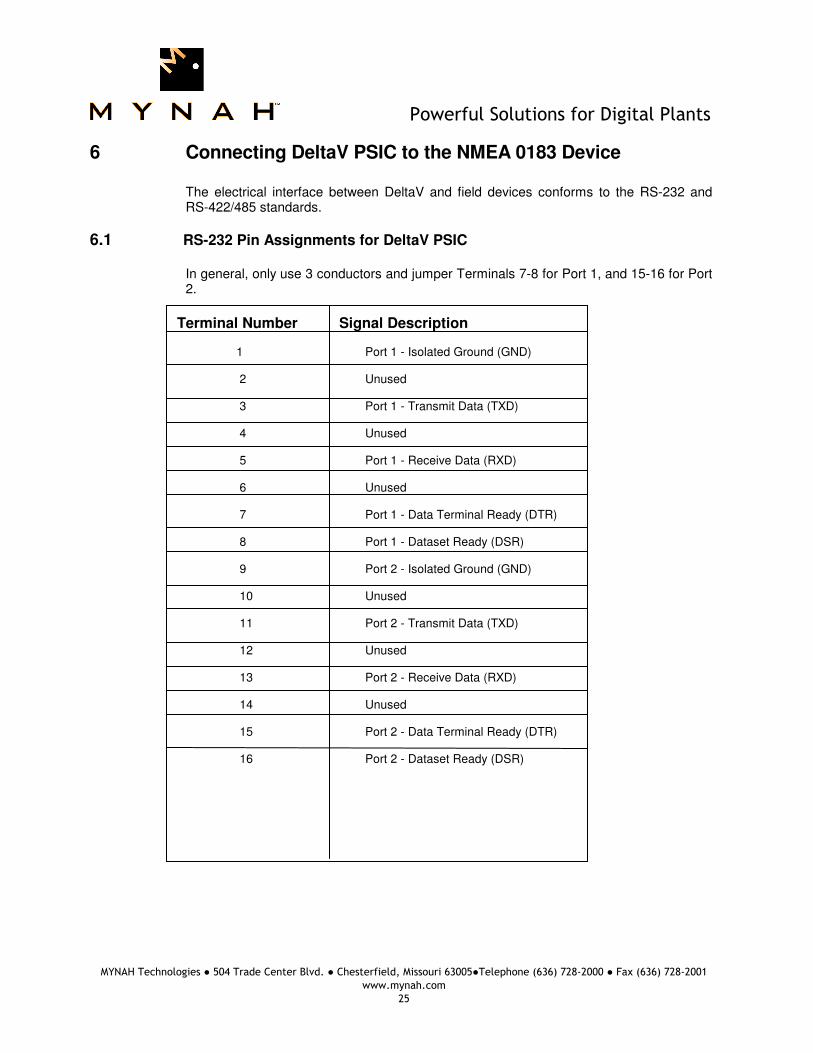
6 Connecting DeltaV PSIC to the NMEA 0183 Device
The electrical interface between DeltaV and field devices conforms to the RS-232 and RS-422/485 standards.
6.1 RS-232 Pin Assignments for DeltaV PSIC
In general, only use 3 conductors and jumper Terminals 7-8 for Port 1, and 15-16 for Port 2.
Terminal Number Signal Description 1 Port 1 - Isolated Ground (GND) 2 Unused 3 Port 1 - Transmit Data (TXD) 4 Unused 5 Port 1 - Receive Data (RXD) 6 Unused 7 Port 1 - Data Terminal Ready (DTR) 8 Port 1 - Dataset Ready (DSR) 9 Port 2 - Isolated Ground (GND) 10 Unused 11 Port 2 - Transmit Data (TXD) 12 Unused 13 Port 2 - Receive Data (RXD) 14 Unused 15 Port 2 - Data Terminal Ready (DTR) 16 Port 2 - Dataset Ready (DSR)

Powerful Solutions for Digital Plants
MYNAH Technologies ● 504 Trade Center Blvd. ● Chesterfield, Missouri 63005●Telephone (636) 728-2000 ● Fax (636) 728-2001
www.mynah.com
26
6.2 RS-422/485 Pin Assignments for DeltaV PSIC
Terminal Number Signal Description 1 Port 1 - Isolated Ground (GND) 2 Port 1 Half Duplex Data+/Full Duplex TXD+ 3 Unused 4 Port 1 - Half Duplex Data -/ Full Duplex TXD- 5 Unused 6 Port 1 - Full Duplex RXD+ 7 Unused 8 Port 1 - Full Duplex RXD- 9 Port 2 - Isolated Ground (GND) 10 Port 2 - Half Duplex Data+ / Full Duplex TXD+ 11 Unused 12 Port 2 - Half Duplex Data-/ Full Duplex TXD- 13 Unused 14 Port 2 - Full Duplex RXD+ 15 Unused 16 Port 2 - Full Duplex RXD-

Powerful Solutions for Digital Plants
MYNAH Technologies ● 504 Trade Center Blvd. ● Chesterfield, Missouri 63005●Telephone (636) 728-2000 ● Fax (636) 728-2001
www.mynah.com
27
7 Technical Support
For technical support or to report a defect, please give MYNAH Technologies a call at (636) 728-2000. If a defect is discovered, please document it in as much detail as possible and then fax your report to us at (636) 728-2001. You can also send us your questions via e-mail. Our addresses are: [email protected] Thank you for using DeltaV.

Powerful Solutions for Digital Plants
MYNAH Technologies ● 504 Trade Center Blvd. ● Chesterfield, Missouri 63005●Telephone (636) 728-2000 ● Fax (636) 728-2001
www.mynah.com
28
8 Appendix – Sentence Details
The following is a description of the message data received and parsed into dataset registers. All numeric (integer and floating point) values are converted and stored into dataset registers directly. For single character data, the translation is as follows: Single character received
Data stored in DeltaV dataset register
0 0 1 1 2 2 3 3 4 4 5 5 6 6 7 7 8 8 9 9 A 101 B 102 C 103 --- --- Z 126 a 201 b 202 c 203 --- --- z 226
AAM Waypoint Arrival Alarm
R1 Status – Arrival circle entered R2 Status – Perpendicular passed at waypoint R3 Arrival circle radius R4 Units of radius, nautical miles R5 Waypoint ID
ALM GPS Almanac Data. This ID comprises more than one message.
A dataset is selected for each expected message. Specify message number in Special Data 1 of the dataset. R1 Total number of messages R2 Message number R3 Satellite PRM number (1-32) R4 GPS week number R5 SV health R6 Eccentricity R7 Almanac Reference time R8 Inclination angle R9 Rate of right Ascension R10 Root of semi-major axis
Powerful Solutions for Digital Plants
MYNAH Technologies ● 504 Trade Center Blvd. ● Chesterfield, Missouri 63005●Telephone (636) 728-2000 ● Fax (636) 728-2001
www.mynah.com
29
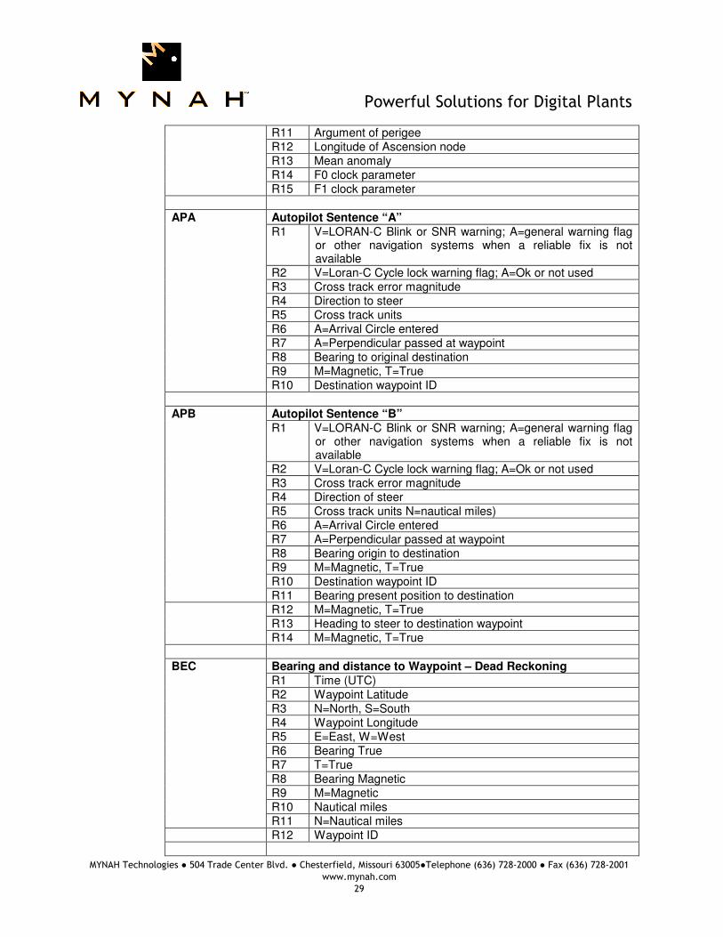
R11 Argument of perigee R12 Longitude of Ascension node R13 Mean anomaly R14 F0 clock parameter R15 F1 clock parameter
APA Autopilot Sentence “A”
R1 V=LORAN-C Blink or SNR warning; A=general warning flag or other navigation systems when a reliable fix is not available
R2 V=Loran-C Cycle lock warning flag; A=Ok or not used R3 Cross track error magnitude R4 Direction to steer R5 Cross track units R6 A=Arrival Circle entered R7 A=Perpendicular passed at waypoint R8 Bearing to original destination R9 M=Magnetic, T=True R10 Destination waypoint ID
APB Autopilot Sentence “B”
R1 V=LORAN-C Blink or SNR warning; A=general warning flag or other navigation systems when a reliable fix is not available
R2 V=Loran-C Cycle lock warning flag; A=Ok or not used R3 Cross track error magnitude R4 Direction of steer R5 Cross track units N=nautical miles) R6 A=Arrival Circle entered R7 A=Perpendicular passed at waypoint R8 Bearing origin to destination R9 M=Magnetic, T=True R10 Destination waypoint ID R11 Bearing present position to destination
R12 M=Magnetic, T=True R13 Heading to steer to destination waypoint R14 M=Magnetic, T=True
BEC Bearing and distance to Waypoint – Dead Reckoning
R1 Time (UTC) R2 Waypoint Latitude R3 N=North, S=South R4 Waypoint Longitude R5 E=East, W=West R6 Bearing True R7 T=True R8 Bearing Magnetic R9 M=Magnetic R10 Nautical miles R11 N=Nautical miles
R12 Waypoint ID

Powerful Solutions for Digital Plants
MYNAH Technologies ● 504 Trade Center Blvd. ● Chesterfield, Missouri 63005●Telephone (636) 728-2000 ● Fax (636) 728-2001
www.mynah.com
30
BOD Bearing – Waypoint to Waypoint R1 Bearing Degrees, TRUE R2 T = True R3 Bearing Degrees, Magnetic R4 M = Magnetic R5 TO Waypoint R6 FROM Waypoint
BWC Bearing and distance to Waypoint – latitude, N/S, Longitude,
E/W, UTC, Status R1 Time (UTC)
R2 Waypoint Latitude R3 N = North, S = South R4 Waypoint Longitude R5 E = East, W = West R6 Bearing, True R7 T = True R8 Bearing, Magnetic R9 M = Magnetic R10 Nautical Miles R11 N = Nautical Miles R12 Waypoint ID
BWR Bearing and distance to Waypoint – Rhumb line latitude, N/S, Longitude, E/W, UTC, Status
R1 Time (UTC) R2 Waypoint Latitude R3 N = North, S = South R4 Waypoint Longitude R5 E = East, W = West R6 Bearing, True R7 T = True R8 Bearing, Magnetic R9 M = Magnetic R10 Nautical Miles R11 N = Nautical Miles R12 Waypoint ID
BWW Bearing – Waypoint to Waypoint
R1 Bearing Degrees, TRUE R2 T = True R3 Bearing Degrees, Magnetic R4 M = Magnetic R5 TO Waypoint R6 FROM Waypoint

Powerful Solutions for Digital Plants
MYNAH Technologies ● 504 Trade Center Blvd. ● Chesterfield, Missouri 63005●Telephone (636) 728-2000 ● Fax (636) 728-2001
www.mynah.com
31
DBK Depth below Keel
R1 Depth, feet R2 f = feet R3 Depth, meters R4 M = meters R5 Depth, Fathoms R6 F = Fathoms
DBS Depth below surface
R1 Depth, feet R2 f = feet R3 Depth, meters R4 M = meters R5 Depth, Fathoms R6 F = Fathom
DBT Depth below Transducer
R1 Depth, feet R2 f = feet R3 Depth, meters R4 M = meters R5 Depth, Fathoms R6 F = Fathom
DPT Heading – Deviation and Variation
R1 Depth, meters R2 Offset from transducer;
Positive means distance from transducer to water line, Negative means distance from transducer to keel
FSI Frequency Set Information
R1 Transmitting Frequency R2 Receiving Frequency R3 Communications Mode (NEA Syntax 2) R4 Power Level
GGA Global Positioning System Fix Data, Time, Position and fix
related data for a GPS receiver R1 Time (UTC) R2 Latitude R3 N or S (North or South) R4 Longitude R5 E or W (East or West) R6 GPS Quality Indicator,
0 – fix not available, 1 – GPS fix, 2 – Differential GPS fix
R7 Number of satellites in view, 00 – 12 R8 Horizontal Dilution of precision R9 Antenna Altitude above/below mean-sea-level (geoid) R10 Units of antenna altitude, meters

Powerful Solutions for Digital Plants
MYNAH Technologies ● 504 Trade Center Blvd. ● Chesterfield, Missouri 63005●Telephone (636) 728-2000 ● Fax (636) 728-2001
www.mynah.com
32
R11 Geoidal separation, the difference between the WGS-84 earth ellipsoid and the mean-sea-level (geoid), “-“ means mean-sea-level below ellipsoid
R12 Units of geoidal separation, meters R13 Age of differential GPS data, time in seconds since last
SC104 R14 Differential reference station ID, 0000-1023
GLC Geographic Position, Loran-C
R1 GRI Microseconds/10 R2 Master TOA Microseconds R3 Master TOA Signal Status R4 Time Difference 1 Microseconds R5 Time Difference 1 Signal Status R6 Time Difference 2 Microseconds R7 Time Difference 2 Signal Status R8 Time Difference 3 Microseconds R9 Time Difference 3 Signal Status R10 Time Difference 4 Microseconds R11 Time Difference 4 Signal Status R12 Time Difference 5 Microseconds R13 Time Difference 5 Signal Status
GLL Geographic Position – Latitude/Longitude
R1 Latitude R2 N or S (North or South) R3 Longitude R4 E or W (East or West) R5 Time (UTC) R6 Status A – Data Valid, V – Data Invalid
GSA GPS DOP and active satellites
R1 Selection mod R2 Mode R3 ID of 1st satellite use for fix R4 ID of 2nd satellite use for fix R5 ID of 3rd satellite use for fix R6 ID of 4th satellite use for fix R7 ID of 5th satellite use for fix R8 ID of 6th satellite use for fix R9 ID of 7th satellite use for fix R10 ID of 8th satellite use for fix R11 ID of 9th satellite use for fix R12 ID of 10th satellite use for fix R13 ID of 11th satellite use for fix R14 ID of 12th satellite use for fix R15 PDOP in meters R16 HDOP in meters R17 VDOP in meters
Powerful Solutions for Digital Plants
MYNAH Technologies ● 504 Trade Center Blvd. ● Chesterfield, Missouri 63005●Telephone (636) 728-2000 ● Fax (636) 728-2001
www.mynah.com
33
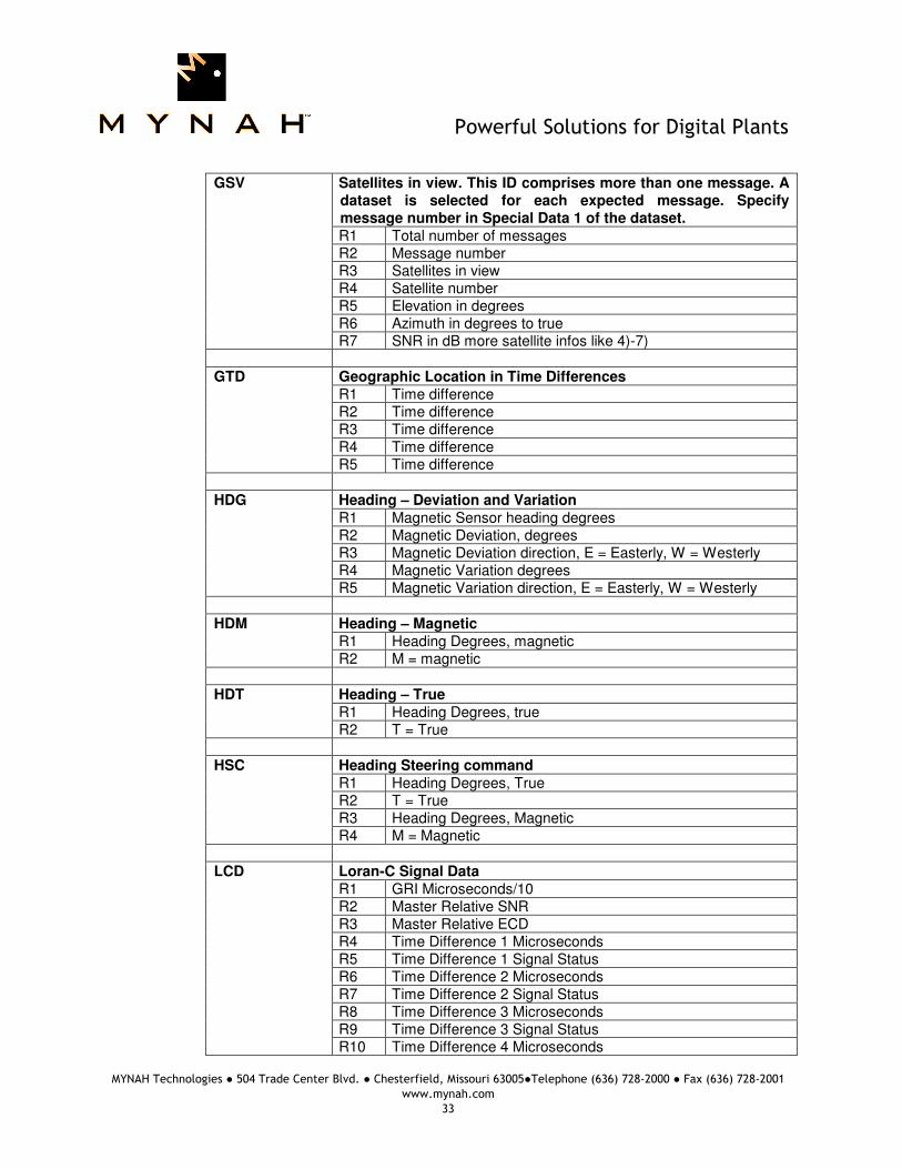
GSV Satellites in view. This ID comprises more than one message. A
dataset is selected for each expected message. Specify message number in Special Data 1 of the dataset. R1 Total number of messages R2 Message number R3 Satellites in view R4 Satellite number R5 Elevation in degrees R6 Azimuth in degrees to true R7 SNR in dB more satellite infos like 4)-7)
GTD Geographic Location in Time Differences
R1 Time difference R2 Time difference R3 Time difference R4 Time difference R5 Time difference
HDG Heading – Deviation and Variation
R1 Magnetic Sensor heading degrees R2 Magnetic Deviation, degrees R3 Magnetic Deviation direction, E = Easterly, W = Westerly R4 Magnetic Variation degrees R5 Magnetic Variation direction, E = Easterly, W = Westerly
HDM Heading – Magnetic
R1 Heading Degrees, magnetic R2 M = magnetic
HDT Heading – True
R1 Heading Degrees, true R2 T = True
HSC Heading Steering command
R1 Heading Degrees, True R2 T = True R3 Heading Degrees, Magnetic R4 M = Magnetic
LCD Loran-C Signal Data
R1 GRI Microseconds/10 R2 Master Relative SNR R3 Master Relative ECD R4 Time Difference 1 Microseconds R5 Time Difference 1 Signal Status R6 Time Difference 2 Microseconds R7 Time Difference 2 Signal Status R8 Time Difference 3 Microseconds R9 Time Difference 3 Signal Status R10 Time Difference 4 Microseconds

Powerful Solutions for Digital Plants
MYNAH Technologies ● 504 Trade Center Blvd. ● Chesterfield, Missouri 63005●Telephone (636) 728-2000 ● Fax (636) 728-2001
www.mynah.com
34
R11 Time Difference 4 Signal Status R12 Time Difference 5 Microseconds R13 Time Difference 5 Signal Status
MSK MSK Receiver Interface (for DGPS Beacon Receivers)
R1 Frequency in kHz (283.5 to 325.0) R2 Frequency Selection
M1 = Manual A1 = Automatic (field 1 empty)
R3 MSK bit rate (100 or 200) R4 Bit Rate Selection
M2 = Manual A2 = Automatic (field 3 empty)
R5 Period of output of performance status message, 0 to 100 seconds ($CRMSS)
MTW Water Temperature
R1 Degrees R2 Unit of Measurement, Celsius
MWD Weather
Format Unknown MWV Wind Speed and Angle
R1 Wind Angle, 0 to 360 Degrees R2 Reference, R = Relative, T = True R3 Wind Speed R4 Wind Speed Units, K/M/N R5 Status, A = Data Valid
OSD Own ship data
R1 Heading, degrees true R2 Status, A = Data Valid R3 Vessel Course, degrees True R4 Course Reference R5 Vessel Speed R6 Speed Reference R7 Vessel Set, degrees True R8 Vessel drift (speed) R9 Speed Units
ROO Waypoints in active route
R1 Waypoint ID RX More waypoints
Powerful Solutions for Digital Plants
MYNAH Technologies ● 504 Trade Center Blvd. ● Chesterfield, Missouri 63005●Telephone (636) 728-2000 ● Fax (636) 728-2001
www.mynah.com
35
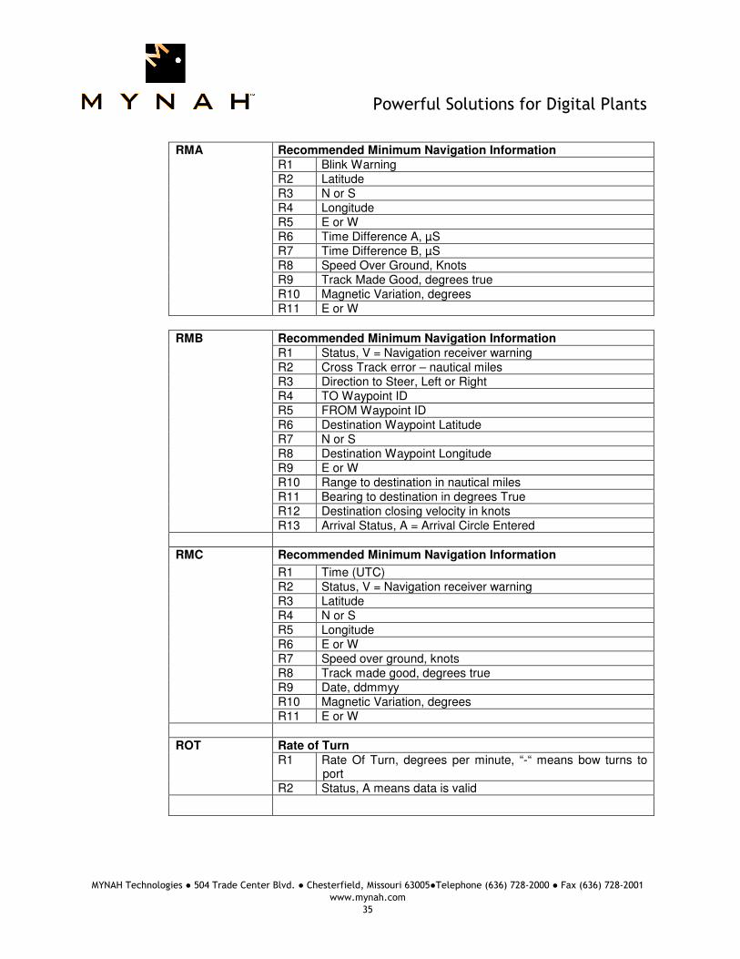
RMA Recommended Minimum Navigation Information
R1 Blink Warning R2 Latitude R3 N or S R4 Longitude R5 E or W R6 Time Difference A, µS R7 Time Difference B, µS R8 Speed Over Ground, Knots R9 Track Made Good, degrees true R10 Magnetic Variation, degrees R11 E or W
RMB Recommended Minimum Navigation Information R1 Status, V = Navigation receiver warning R2 Cross Track error – nautical miles R3 Direction to Steer, Left or Right R4 TO Waypoint ID R5 FROM Waypoint ID R6 Destination Waypoint Latitude R7 N or S R8 Destination Waypoint Longitude R9 E or W R10 Range to destination in nautical miles R11 Bearing to destination in degrees True R12 Destination closing velocity in knots R13 Arrival Status, A = Arrival Circle Entered
RMC Recommended Minimum Navigation Information
R1 Time (UTC) R2 Status, V = Navigation receiver warning R3 Latitude R4 N or S R5 Longitude R6 E or W R7 Speed over ground, knots R8 Track made good, degrees true R9 Date, ddmmyy R10 Magnetic Variation, degrees R11 E or W
ROT Rate of Turn
R1 Rate Of Turn, degrees per minute, “-“ means bow turns to port
R2 Status, A means data is valid
Powerful Solutions for Digital Plants
MYNAH Technologies ● 504 Trade Center Blvd. ● Chesterfield, Missouri 63005●Telephone (636) 728-2000 ● Fax (636) 728-2001
www.mynah.com
36
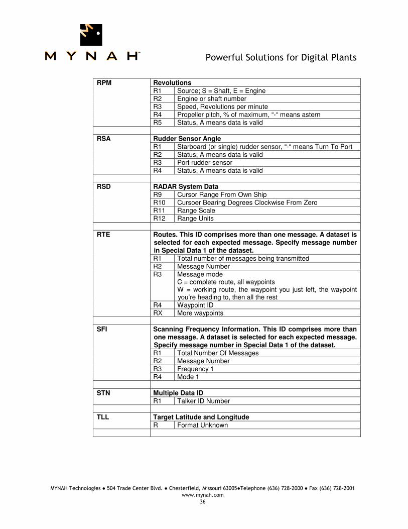
RPM Revolutions
R1 Source; S = Shaft, E = Engine R2 Engine or shaft number R3 Speed, Revolutions per minute R4 Propeller pitch, % of maximum, “-“ means astern R5 Status, A means data is valid
RSA Rudder Sensor Angle
R1 Starboard (or single) rudder sensor, “-“ means Turn To Port R2 Status, A means data is valid R3 Port rudder sensor R4 Status, A means data is valid
RSD RADAR System Data
R9 Cursor Range From Own Ship R10 Cursoer Bearing Degrees Clockwise From Zero R11 Range Scale R12 Range Units
RTE Routes. This ID comprises more than one message. A dataset is
selected for each expected message. Specify message number in Special Data 1 of the dataset. R1 Total number of messages being transmitted R2 Message Number R3 Message mode
C = complete route, all waypoints W = working route, the waypoint you just left, the waypoint you’re heading to, then all the rest
R4 Waypoint ID RX More waypoints
SFI Scanning Frequency Information. This ID comprises more than
one message. A dataset is selected for each expected message. Specify message number in Special Data 1 of the dataset. R1 Total Number Of Messages R2 Message Number R3 Frequency 1 R4 Mode 1
STN Multiple Data ID
R1 Talker ID Number TLL Target Latitude and Longitude
R Format Unknown

Powerful Solutions for Digital Plants
MYNAH Technologies ● 504 Trade Center Blvd. ● Chesterfield, Missouri 63005●Telephone (636) 728-2000 ● Fax (636) 728-2001
www.mynah.com
37
TTM Tracked Target Message
R1 Target Number R2 Target Distance R3 Bearing from own ship R4 Bearing Units R5 Target speed R6 Target Course R7 Course Units R8 Distance of closest-point-of-approach R9 Time until closest-point-of-approach “-“ means increasing R10 “-“ means increasing R11 Target name R12 Target Status R13 Reference Target
VBW Dual Ground/Water speed
R1 Longitudinal water speed, “-“ means astern R2 Transverse water speed, “-“ means port R3 Status, A = data valid R4 Longitudinal ground speed, “-“ astern R5 Transverse ground speed, “-“ means port R6 Status, A = data valid
VDR Set and Drift
R1 Degrees True R2 T = True R3 Degrees Magnetic R4 M = Magnetic R5 Knots (speed of current) R6 N = Knots
VHW Water Speed and Heading
R1 Degrees True R2 T = True R3 Degrees Magnetic R4 M = Magnetic R5 Knots (speed of current) R6 N = Knots R7 Kilometers (speed of vessel relative to the water) R8 K = Kilometers
VLW Distance Traveled through water
R1 Total cumulative distance R2 N = Nautical Miles R3 Distance since Reset R4 N = Nautical Miles

Powerful Solutions for Digital Plants
MYNAH Technologies ● 504 Trade Center Blvd. ● Chesterfield, Missouri 63005●Telephone (636) 728-2000 ● Fax (636) 728-2001
www.mynah.com
38
VPW Speed – measured parallel to wind
R1 Speed, “-“ means downwind R2 N = Knots R3 Speed, “-“ means downwind R4 M = Meters per second
VTG Track made good and Ground speed
R1 Track Degrees R2 T = True R3 Track Degrees R4 M = Magnetic R5 Speed Knots R6 N = Knots R7 Speed Kilometers Per Hour R8 K = Kilometers Per Hour
VWR Relative Wind Speed and Angle
R1 Wind Direction magnitude in degrees R2 L or R - Wind direction Left/Right of bow R3 Speed R4 N = Knots R5 Speed R6 M = Meters Per Second R7 Speed R8 K = Kilometers Per Hour
VWT Weather (format same as VWR) WCV Waypoint Closure Velocity
R1 Velocity R2 N = Knots R3 Waypoint ID
WNC Distance – Waypoint to Waypoint
R1 Distance, Nautical Miles R2 N = Nautical Miles R3 Distance, Kilometers R4 K = Kilometers R5 TO Waypoint R6 FROM Waypoint
WPL Waypoint Location
R1 Latitude R2 N or S (North or South) R3 Longitude R4 E or W (East or West) R5 Waypoint Name
Powerful Solutions for Digital Plants
MYNAH Technologies ● 504 Trade Center Blvd. ● Chesterfield, Missouri 63005●Telephone (636) 728-2000 ● Fax (636) 728-2001
www.mynah.com
39
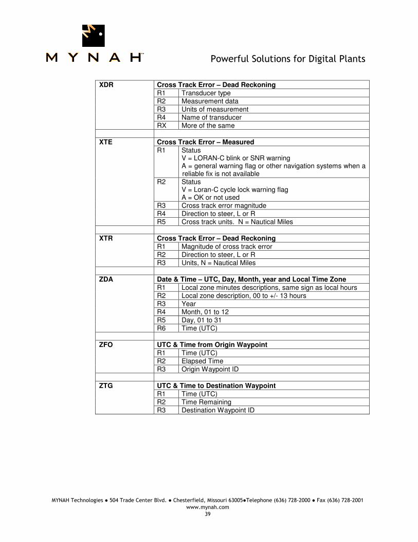
XDR Cross Track Error – Dead Reckoning
R1 Transducer type R2 Measurement data R3 Units of measurement R4 Name of transducer RX More of the same
XTE Cross Track Error – Measured
R1 Status V = LORAN-C blink or SNR warning A = general warning flag or other navigation systems when a reliable fix is not available
R2 Status V = Loran-C cycle lock warning flag A = OK or not used
R3 Cross track error magnitude R4 Direction to steer, L or R R5 Cross track units. N = Nautical Miles
XTR Cross Track Error – Dead Reckoning
R1 Magnitude of cross track error R2 Direction to steer, L or R R3 Units, N = Nautical Miles
ZDA Date & Time – UTC, Day, Month, year and Local Time Zone
R1 Local zone minutes descriptions, same sign as local hours R2 Local zone description, 00 to +/- 13 hours R3 Year R4 Month, 01 to 12 R5 Day, 01 to 31 R6 Time (UTC)
ZFO UTC & Time from Origin Waypoint
R1 Time (UTC) R2 Elapsed Time R3 Origin Waypoint ID
ZTG UTC & Time to Destination Waypoint
R1 Time (UTC) R2 Time Remaining R3 Destination Waypoint ID

Powerful Solutions for Digital Plants
MYNAH Technologies ● 504 Trade Center Blvd. ● Chesterfield, Missouri 63005●Telephone (636) 728-2000 ● Fax (636) 728-2001
www.mynah.com
40
9 Revision History
Revision Number
Checked By
Approved By
Date Description
1.55 NFW NFW Sept, 2011 Internal Release 1.56 NFW NFW Nov, 2011 Added NMEA sentence format details.
Recommended