cEa SEriES
CEILING EXPOSED HORIZONTAL FAN COIL UNITS
Producing Quality Heating & Cooling Equipment For Over 50 Years
United Electric Company, L.P.
501 Galveston St. • Wichita Falls, TX 76301 • 940-397-2100 • Fax: 940-397-2166 • www.magicaire.com
MAGIC AIRE CE SERIES FAN COILS ARE ETLLISTED TO U.S. AND CANADIAN SAFETY STANDARDS
AND ARE ASSEMBLED TO ORDER FOR COMPETITIVE DELIVERY.
The Premium Quality Fan Coil Units for
Horizontal Application Hydronic or Electric Heat
CEA 1.0 06/16/2008

B1
B
STAMPEDRA LOUVER
STAMPEDRA LOUVERAND FILTER
SUPPLYAIR
SUPPLYAIR
HINGED SERVICEACCESS PANEL(TYP)
DAMPER
FILTER (TYP)
8.5"
BOTTOM RA ONLY(OPTION “B”)
B
SOLIDBOTTOM ANDACCESS PANEL
SUPPLYAIR
RA GRILLE
REAR RA ONLY(OPTION “R”)
BOTTOM RA, REAR OA(OPTIONS “D” AND “F”)
B
STAMPEDRA LOUVER
SUPPLYAIR
DAMPER
BOTTOM RA, TOP OA(OPTIONS “E” AND “G”) TOP
OA DUCTCOLLAR
NOTES:1. Legend: RA = Return Air OA = Outside Air2. Refer to Nomenclature page for cabinet options. Refer
to Coil Option Schedule for available coil combinations.3. For cabinet options “E” and “G”, damper function is
0 - 50% RA and 50 - 100% OA nominal.
Page 2CEA 1.0 6/16/2008
CE Series
Decorative, slim cabinet designed for exposed ceiling applications. Unit includes double deflection discharge grille. Cabinet is galva-nealed steel with baked powder Polar Ice color coating for the ultimate in durability. All panels are lined with acoustic and thermal glass fiber insulation. Filters are one inch throwaway and are accessed through the hinged bottom service panel. Optional mixed air damper for 100% outside air requirements.
SNOISNEMID GNIPPIHSTHGIEW EZISRETLIF
LANOITPOTCUD.CSID
.NNOC
LANOITPOTCUDRAER
.NNOCLEDOM A B 1B
CEA02 "33 6"3 8"2 021 x 181x01 15x57.6 18x5.8
CEA04 "33 6"3 8"2 109 x 181x01 18x57.6 18x5.8
CEA06 "24 6"3 8"2 147 x 172x01 27x57.6 36x5.8
CEA08 "15 6"3 8"2 551 x 163x01 36x57.6 36x5.8
CEA10 "06 6"3 28" 171 x 154x01 45x57.6 45x5.8
CEA12 "96 6"3 8"2 252 x 145x01 54x57.6 54x5.8
.TWS.D.O"8/5SNOITCENNOCLIOCLLA
.T.P.M"4/3SNOITCENNOCNIARDLLA
KNOCKOUTS FOR PIPINGREAR
6"
3"
2"
A
TOP VIEW
FRONT
12"
FRONT VIEW
MOUNTINGHOLES X 4
REAR
KNOCKOUTSFOR PIPING
OPTIONALOA DUCTCOLLAR

Page 3CEA 1.0 6/16/2008
GUIDE SPECIFICATIONS
Magic Aire Fan Coil Unit HVAC Guide Specifications
Size Range: 200 to 1200 Nominal CFMMagic Aire Model CE
Part 1 — General1.01 SYSTEM DESCRIPTIONHorizontal, 2-pipe or 4-pipe, room fan coil unit with painted finish cabinet for exposed installation or ducting.
1.02 QUALITY ASSURANCEUnit shall be tested in accordance with ARI Standard 440 and base unit ETL certified. Each coil shall be factory tested for leakage at 450 psig air pressure with coil submerged in water. Insulation and adhesive shall meet NFPA-90A requirements for flame spread and smoke generation. All equipment wiring shall comply with NEC requirements.
1.03 DELIVERY, STORAGE AND HANDLINGEach unit shall be individually packaged from point of manufacture. Unit shall be handled and stored in accordance with the manufacturer’s instructions.
Part 2 — Product2.01 EQUIPMENTGeneral:Factory-assembled, horizontal, blow-thru type fan coil for exposed ceiling or ducted installations. Unit shall be complete with water coil(s), fan(s), motor(s), drain pan, and all required wiring, piping, controls and special features.
A. Base Unit: 1. Casing to consist of heavy gauge galvanized steel insulated
with 1/2” fiberglass Tufskin insulation. Units shall pass 500 hour salt spray test as described in ASTM B-117.
2. Cabinet shall include a removable bottom access panel with stamped return-air grille or ducted return air, filter rack and 1-in. fiberglass throwaway filter. The panel shall be fastened with slotted head, positive-locking quarter-turn fasteners. The cabinet shall be coated with a Polar Ice baked finish.
3. The drain pan shall be constructed of galvanized steel extending the entire length and width of the coil(s) and shall be pitched for drainage. The drain connection shall be ¾” FPT.
B. Fans: Direct-driven, double-width fan wheels with forward curved
blades shall be statically and dynamically balanced. The housing shall be constructed of heavy gauge galvanized steel with die-formed inlet cones. Fan wheels shall be constructed of galvanized steel.
C. Coils: 1. Standard base unit shall be equipped with a 3-row, 4-row
or 5-row coil for installation in a 2 or 4-pipe system. Hydronic coil options include split heating/cooling coils in combinations not exceeding 5 rows.
2. Factory installed electric resistance heating coils in may be 1.5 to 10kW depending on unit size and voltage.
3. All coils shall have 3/8-in. copper tubes and aluminum fins. Coil fins are mechanically bonded to tube joints. The copper tubes comply with the ASTM B-75. The fin thickness is 0.0045-in and tube thickness is 0.014-in. All coils are tested with air under water.
4. Unit with electric heat shall have electric resistance heaters mounted on the entering air side of the water coil. Heaters shall include high limit cutout with auto reset and contactor.
5. When fan motor and electric heater are selected at the same voltage and connected to a single power source, a junction box and fuse shall be factory furnished and installed to protect the motor and control circuit.
D. Controls and Safeties: Unit shall be furnished with an optional 3-speed, 4-position
fan switch on a wall plate for field mounting. The fan motor(s) shall be equipped with integral automatic temperature reset for motor protection.
E. Operating Characteristics: 1. A unit with single hydronic coil installed in a 2-pipe system
shall be capable of providing heating or cooling as determined by the operating mode of the central water supply system.
2. A unit with two hydronic coils installed in a 4-pipe system shall be capable of providing heating and cooling, controlled as determined by field-provided and installed valves and controls.
3. Electrical Requirements: The unit power supply shall be single phase, 60 Hz. The
standard unit is 120 volt, but 208/240V and 277V options are available.
F. Motor(s): Fan motors shall be 3-speed; permanent split capacitor type,
with sleeve type bearings and factory-sealed oil reservoirs to ensure lubrication.

Page 4CEA 1.0 6/16/2008
MODEL NOMENCLATURE
CEA Model Number NomenclaturePosition 1 2 3 4 5 6 7 8 9 10 11 12 13 14
Example C E A 0 6 B A R A 1 A A A M
Model Series M -- Not UsedCEA--
DRAIN PAN OPTIONSA --
Unit Size B --02 --04 -- RETURN AIR CABINET06 -- B -- Bottom Return Only08 --10 --12 --
0 --B --C -- R -- Rear Return OnlyD --
CONTROLSHEATING COIL A --
B --A -- C --1 -- D --2 -- E --
F --CONTROLS NOTES:
B-- 1. Svc disconnect switch is for non-electric heat
C-- units only.
D--E-- MOTOR POWER SUPPLYF-- 1 --G-- 2 --H-- 3 --J-- 4 --K-- 5 --HEATING COIL NOTES: MOTOR POWER SUPPLY NOTES:
tsum dleiF .yrotcaf ta V042 rof deriw eb llahs tinU .1 .snoitanibmoc elbaliava rof eludehcS noitpO EC ot refeR .1
.V802 ot )dedivorp fi( pat remrofsnart hctiws tsum dleiF .yrotcaf yb V042 ta deriw eb llahs slortnoc taeh cirtcelE .2
switch transformer tap for 208V operation.
3. Maximum of 5 total rows allowed (cooling coil rows plus heating FUTURE USEcoil rows). A -- Not Used4. Nominal kW is at 240V. 208V heaters are derated from 240V.
COIL CONFIGURATION
A -- Right Hand (Cooling & Heating Coil) or N/A1.5 2.0 2.5 3.0 4.0 5.0 6.0 8.0 10.0 L -- Left Hand (Cooling & Heating Coil)
02 X X X M -- Opp Cnx- Right Hand Cooling04 X X X N -- Opp Cnx- Left Hand Cooling06 X X X X X R -- Right Hand (Cooling & Heating Coil)08 X X X X X S -- Left Hand (Cooling & Heating Coil)10 X X X X X T -- Opp Cnx- Right Hand Cooling12 X X X U -- Opp Cnx- Left Hand Cooling
:SETON NOITARUGIFNOC LIOC.V772 rof elbaliava ton taeh cirtcelE
1. Electric heat is available only in Pre-Heat.
2. "Left Hand" and "Right Hand" defined as looking at the filters
in the direction of airflow.
Heat Position
Pre-Heat
Re-Heat
Connection Hand
Galvanized Stainless Steel
Junction Box Only
24V Control + Timer + Svc Disconnect Switch
24V Fan Control24V Fan Control w/ Svc Disconnect SwitchSvc Disconnect Switch Only24V Control + Timer
D -- Bottom Return Air/Rear Outside Air w/oActuator
PRIMARY COIL TYPE AND CAPACITY
N/AMetering
None N/A
TypeNone
RowsN/A
Type
Horizontal Direct Drive Unit,Uncased
400 CFM600 CFM800 CFM
5.0MFC 0021.01.52.0
1200 CFM 3.0
Nominal Tons
N/AChilled Water/2-Pipe
N/AN/A
1000 CFM 2.5
3
Rows
45
Hot Water21
Nominal kW1.1 kW
kW @ 208VElectric Heat
1.5 kW
3.0 kW4.0 kW
1.5 kW1.9 kW2.3 kW3.0 kW
2.5 kW2.0 kW
High Static120/1/60208/240/1/60
3.8 kW Std. Static120/1/60
208/240/1/60277/1/604.5 kW
6.0 kW7.5 kW
5.0 kW6.0 kW8.0 kW
10.0 kW
Nominal kW
CE Electric Heat Schedule
(120V Only) (208/240V Only)Unit Size
G -- Bottom Return Air/Top Outside Air with Actuator
E -- Bottom Return Air/Top Outside Air w/o Actuator
F -- Bottom Return Air/Rear Outside Air withActuator

Page 5CEA 1.0 6/16/2008
CE SeriesCOIL OPTION SCHEDULE
1.5 2.0 2.5 3.0 4.0 5.0 6.0 8.0 10.0
XX
XX
XX
XX
X X
X X
XXXXX
XXXXX
XXXXX
XXXXXXX
XXXXXXX
XXXXXXX
XX X X X
X X X X X
X X X X X
Notes:
1. Legend: CHW Chilled Water
HW Hot Water
EH Electric Heat
2. Option Schedule indicates available combinations. Refer to nomenclature to specify unit for order.
3. Electric heat not available for 277V.
4. Electric heat - select one option.
5. Coil options: 3 row minimum coil required; 5 rows total maximum; 4-pipe unit configurations are "split" style coils with both coils in same finblock and
are available in 1/3, 1/4, and 2/3 arrangements, preheat or reheat.
02-04
06-10
12
CHW/EH
02-12CHW/HW
5-Row None woR-2woR-1woR-4woR-3
CE Coil Option Schedule
Configuration
Electric Heat - Nominal kW
)ylnO V042/802()ylnO V021(
Cooling Coil/2-Pipe HW Heating Coil (4-Pipe)
Unit Sizes

Page 6CEA 1.0 6/16/2008
CE SeriesELECTRICAL DATA
CHA - CEA Electrical Data - 120V
1201412101014121010
1/10std
1.4 14
1/8hi-static
1.6 14
1/8std
1.8 14
1/4hi-static
3.1 14
1/10 x 2std
1.4 14
1/8 x 2hi-static
1.6 14
Notes:*1. Minimum Wire Gauge is based upon 75C wire at the unit. On 208/240V units the size is based upon the 240V Ratings.2. Size 12 units have two fan motors.
12*2
2.8 3.5 15
NONE NONE 3.8 4.8 15
NONE
2.0 1506
NONE NONE 3.1 3.9 15
0810
NONE
0204
MINWIRESIZE
AWG*1
MOTOR FLA
TOTALELECTRIC HT
(KW)120
1/15std
0.751.5
1/10hi-static
1.1
NONE
120
NONE12.516.72
2.5
NONE
NONE
NONE
NONE
16.712.5
NONE NONE
NONE
21.5
2.5 20.8
2.3
1.1 1.4
UNIT FLA
120
0.813.3
13.6 17.017.8
27.0
1.8
22.2
1.4
21.9 27.4
MINIMUMCIRCUIT
AMPACITY120
16.621.8
0.9
2530
15
15
15202530
120
15
MaximumOvercurrent
PD (A)
20
UNITSIZE
MOTORHP
NONE 1.8
1.6
Voltage
17.421.620.8
ELECTRICHEAT AMPS

Page 7CEA 1.0 6/16/2008
CE SeriesELECTRICAL DATA
CHA - CEA Electrical Data 208/240V
240-208V 240 208 240 208 240 208 240 208 240 208
021/10
hi-static4151518.08.06.06.06.0
0.5 0.5 0.6 0.6 15 15 143 2.25 12.5 10.8 13.0 11.3 16.3 14.2 20 15 124 3.00 16.7 14.4 17.2 14.9 21.5 18.7 25 20 105 3.76 20.8 18.1 21.3 18.6 26.7 23.2 30 25 10
0.6 0.6 0.8 0.8 15 15 143 2.25 12.5 10.8 13.1 11.4 16.4 14.3 20 15 124 3.00 16.7 14.4 17.3 15.0 21.6 18.8 25 20 105 3.76 20.8 18.1 21.4 18.7 26.8 23.3 30 25 10
0.6 0.6 0.8 0.8 15 15 143 2.25 12.5 10.8 13.1 11.4 16.4 14.3 20 15 124 3.00 16.7 14.4 17.3 15.0 21.6 18.8 25 20 105 3.76 20.8 18.1 21.4 18.7 26.8 23.3 30 25 106 4.51 25.0 21.7 25.6 22.3 32.0 27.8 35 30 88 6.01 33.3 28.9 33.9 29.5 42.4 36.9 45 40 8
0.8 0.8 1.0 1.0 15 15 143 2.25 12.5 10.8 13.3 11.6 16.6 14.5 20 15 124 3.00 16.7 14.4 17.4 15.2 21.8 19.0 25 20 105 3.76 20.8 18.1 21.6 18.8 27.0 23.5 30 25 106 4.51 25.0 21.7 25.8 22.4 32.2 28.0 35 30 88 6.01 33.3 28.9 34.1 29.7 42.6 37.1 45 40 8
0.9 0.9 1.1 1.1 15 15 143 2.25 12.5 10.8 13.4 11.7 16.8 14.7 20 15 124 3.00 16.7 14.4 17.6 15.3 22.0 19.2 25 20 105 3.76 20.8 18.1 21.7 19.0 27.2 23.7 30 25 106 4.51 25.0 21.7 25.9 22.6 32.4 28.2 35 30 88 6.01 33.3 28.9 34.2 29.8 42.8 37.2 45 40 8
10 7.51 41.7 36.1 42.6 37.0 53.2 46.3 60 50 61.6 1.6 2.0 2.0 15 15 14
3 2.25 12.5 10.8 14.1 12.4 17.6 15.5 20 20 124 3.00 16.7 14.4 18.3 16.0 22.8 20.1 25 25 105 3.76 20.8 18.1 22.4 19.7 28.0 24.6 30 25 106 4.51 25.0 21.7 26.6 23.3 33.3 29.1 35 30 88 6.01 33.3 28.9 34.9 30.5 43.7 38.1 45 40 8
10 7.51 41.7 36.1 43.3 37.7 54.1 47.1 60 50 61.2 1.2 1.5 1.5 15 15 14
6 4.51 25.0 21.7 26.2 22.9 32.8 28.6 35 30 88 6.01 33.3 28.9 34.5 30.1 43.2 37.6 45 40 8
10 7.51 41.7 36.1 42.9 37.3 53.6 46.6 60 50 61.5 1.5 1.9 1.9 15 15 14
6 4.51 25.0 21.7 26.5 23.2 33.2 29.0 35 30 88 6.01 33.3 28.9 34.9 30.4 43.6 38.0 45 40 8
10 7.51 41.7 36.1 43.2 37.7 54.0 47.1 60 50 6
Notes:*1. Minimum Wire Gauge is based upon 75C wire at the unit. On 208/240V units the size is based upon the 240V Ratings.2. Size 12 units have two fan motors.
NONE
NONE NONE
0.77
0.9
NONE
MINWIRESIZE
AWG*1
MOTOR FLA
TOTALELECTRIC HT
(KW)
ELECTRICHEAT AMPS
MINIMUMCIRCUIT
AMPACITYUNIT FLA
MaximumOvercurrent
PD (A)
12*2
NONE NONE1/10 x 2hi-static
0.77
NONE
1/10 x 2std
0.6
NONE NONE
1/10hi-static
0.6
NONE
0810
1/4hi-static
1.6
NONE
1/8hi-static
1/8std
NONE
06
04
1/10std
0.6
NONE
NONE
1/15std
0.5
NONE NONE
UNITSIZE
MOTORHP
Voltage
NONE NONE
Page 8CEA 1.0 6/16/2008
CE SeriesELECTRICAL DATA
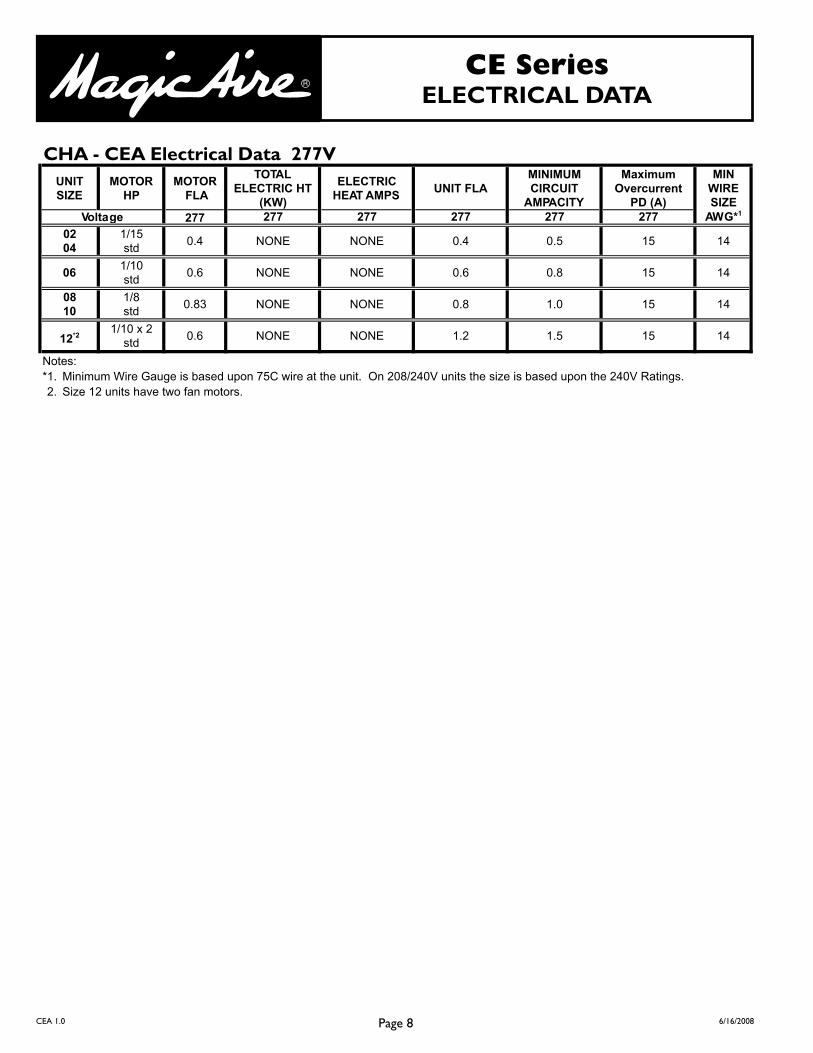
CHA - CEA Electrical Data 277V
2770204
1/15std
0.4 14
061/10std
0.6 14
0810
1/8std
0.83 14
12*21/10 x 2
std0.6 14
Notes:*1. Minimum Wire Gauge is based upon 75C wire at the unit. On 208/240V units the size is based upon the 240V Ratings.2. Size 12 units have two fan motors.
0.4 0.5 15
MOTOR FLA
TOTALELECTRIC HT
(KW)
MINIMUMCIRCUIT
AMPACITY
MaximumOvercurrent
PD (A)
NONE
MINWIRESIZE
AWG*1277 277 277 277 277
ELECTRICHEAT AMPS
UNIT FLA
15
15
NONE NONE 0.8 1.0 15
NONE NONE 1.2 1.5
UNITSIZE
MOTORHP
Voltage
0.6 0.8
NONE NONE
NONE
Page 9CEA 1.0 6/16/2008
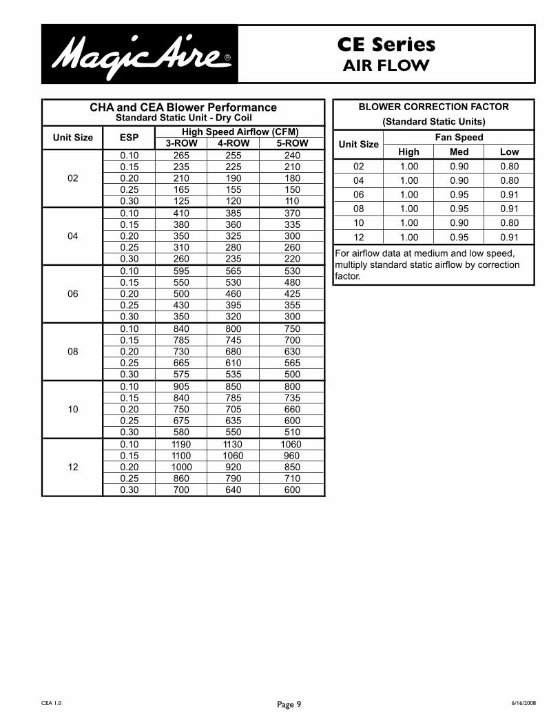
CE SeriesAIR FLOW
High Med Low
02 1.00 0.90 0.80
04 1.00 0.90 0.80
06 1.00 0.95 0.91
08 1.00 0.95 0.91
10 1.00 0.90 0.80
12 1.00 0.95 0.91
BLOWER CORRECTION FACTOR
For airflow data at medium and low speed, multiply standard static airflow by correction factor.
Fan SpeedUnit Size
(Standard Static Units)
3-ROW 4-ROW 5-ROW0.10 265 255 2400.15 235 225 2100.20 210 190 1800.25 165 155 1500.30 125 120 1100.10 410 385 3700.15 380 360 3350.20 350 325 3000.25 310 280 2600.30 260 235 2200.10 595 565 5300.15 550 530 4800.20 500 460 4250.25 430 395 3550.30 350 320 3000.10 840 800 7500.15 785 745 7000.20 730 680 6300.25 665 610 5650.30 575 535 5000.10 905 850 8000.15 840 785 7350.20 750 705 6600.25 675 635 6000.30 580 550 5100.10 1190 1130 10600.15 1100 1060 9600.20 1000 920 8500.25 860 790 7100.30 700 640 600
10
12
02
04
06
08
CHA and CEA Blower PerformanceStandard Static Unit - Dry Coil
Unit Size ESPHigh Speed Airflow (CFM)
Page 10CEA 1.0 6/16/2008
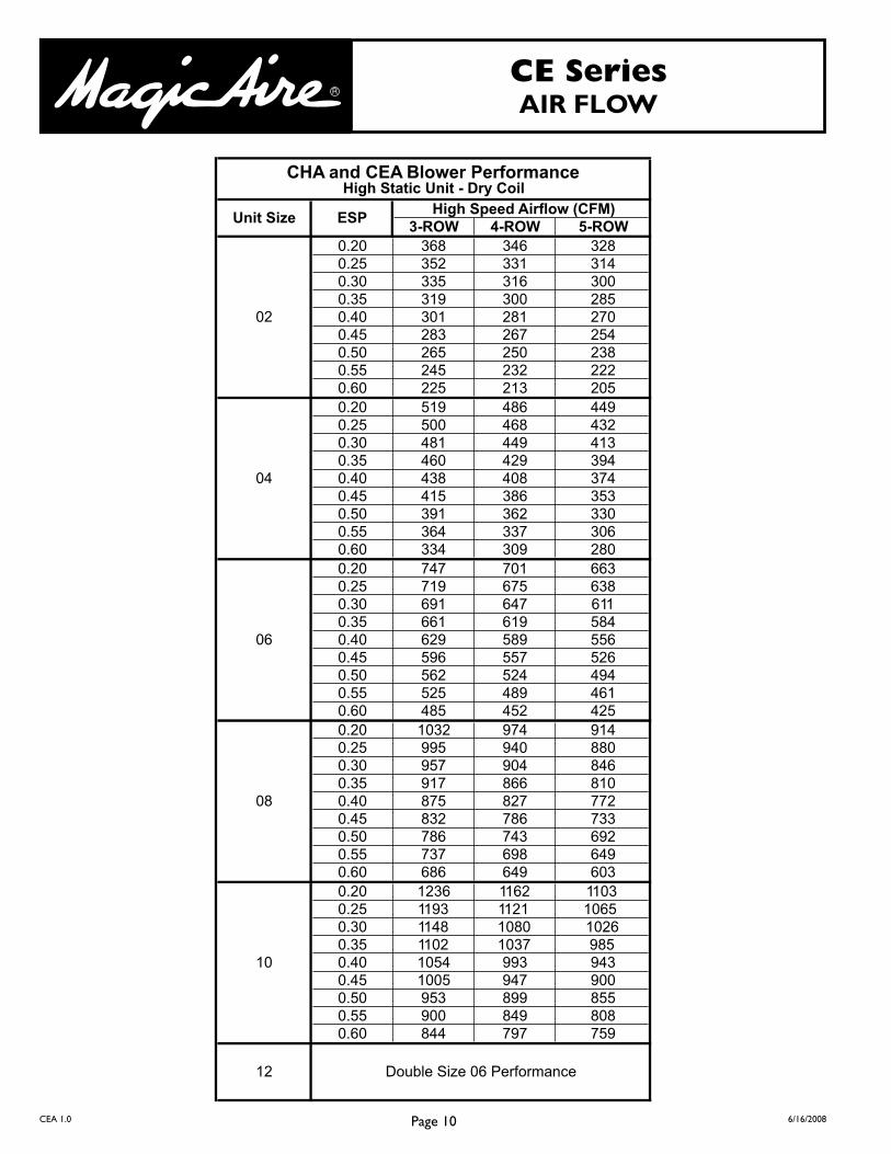
CE SeriesAIR FLOW
3-ROW 4-ROW 5-ROW0.20 368 346 3280.25 352 331 3140.30 335 316 3000.35 319 300 2850.40 301 281 2700.45 283 267 2540.50 265 250 2380.55 245 232 2220.60 225 213 2050.20 519 486 4490.25 500 468 4320.30 481 449 4130.35 460 429 3940.40 438 408 3740.45 415 386 3530.50 391 362 3300.55 364 337 3060.60 334 309 2800.20 747 701 6630.25 719 675 6380.30 691 647 6110.35 661 619 5840.40 629 589 5560.45 596 557 5260.50 562 524 4940.55 525 489 4610.60 485 452 4250.20 1032 974 9140.25 995 940 8800.30 957 904 8460.35 917 866 8100.40 875 827 7720.45 832 786 7330.50 786 743 6920.55 737 698 6490.60 686 649 6030.20 1236 1162 11030.25 1193 1121 10650.30 1148 1080 10260.35 1102 1037 9850.40 1054 993 9430.45 1005 947 9000.50 953 899 8550.55 900 849 8080.60 844 797 759
06
08
12 Double Size 06 Performance
10
02
04
CHA and CEA Blower PerformanceHigh Static Unit - Dry Coil
High Speed Airflow (CFM)ESPUnit Size
Page 11CEA 1.0 6/16/2008
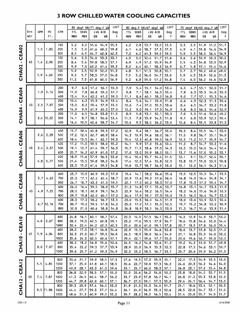
3 ROW CHILLED WATER COOLING CAPACITIES
LWT LWT LWT
CH
A02
- C
EA
02C
HA
04 -
CE
A04
CH
A06
- C
EA
06C
HA
08 -
CE
A08
CH
A10
- C
EA
10C
HA
12 -
CE
A12

Page 12CEA 1.0 6/16/2008
4 ROW CHILLED WATER COOLING CAPACITIESC
HA
02 -
CE
A02
CH
A04
- C
EA
04C
HA
06 -
CE
A06
CH
A08
- C
EA
08C
HA
10 -
CE
A10
CH
A12
- C
EA
12
LWT LWT LWT

Page 13CEA 1.0 6/16/2008
1 ROW HEATING
CH
A02
- C
EA
02C
HA
04 -
CE
A04
CH
A06
- C
EA
06C
HA
08 -
CE
A08
CH
A10
- C
EA
10C
HA
12 -
CE
A12
CH
A02
- C
EA
02C
HA
04 -
CE
A04
CH
A06
- C
EA
06C
HA
08 -
CE
A08
CH
A10
- C
EA
10C
HA
12 -
CE
A12
2 ROW HEATING

Page 14CEA 1.0 6/16/2008
3 ROW HEATING
SROTCAFNOITCERROCGNITAEHRETAWTOH
gniretnE)F(pmeTriA
)F(pmeTretaWgniretnE
001 o 011 o 021 o 031 o 041 o 051 o 061 o 071 o 081 o
05 o 914. 005. 975. 566. 247. 838. 719. 000.1 900.1
55 o 673. 064. 445. 926. 807. 197. 378. 369. 480.1
06 o 533. 914. 005. 975. 566. 247. 838. 719. 000.1
56 o 092. 673. 064. 445. 926. 807. 197. 378. 639.
07 o 152. 533. 914. 005. 975. 566. 247. 838. 179.
57 o 502. 092. 673. 064. 445. 926. 807. 197. 738.
08 o 761. 152. 533. 914. 005. 975. 566. 247. 388.
CH
A04
- C
EA
04C
HA
08 -
CE
A08
CH
A12
- C
EA
12
CH
A02
- C
EA
02C
HA
06 -
CE
A06
CH
A10
- C
EA
10

Page 15CEA 1.0 6/16/2008
4 ROW HEATING
SROTCAFNOITCERROCGNITAEHRETAWTOH
gniretnE)F(pmeTriA
)F(pmeTretaWgniretnE
001 o 011 o 021 o 031 o 041 o 051 o 061 o 071 o 081 o
05 o 914. 005. 975. 566. 247. 838. 719. 000.1 900.1
55 o 673. 064. 445. 926. 807. 197. 378. 369. 480.1
06 o 533. 914. 005. 975. 566. 247. 838. 719. 000.1
56 o 092. 673. 064. 445. 926. 807. 197. 378. 639.
07 o 152. 533. 914. 005. 975. 566. 247. 838. 179.
57 o 502. 092. 673. 064. 445. 926. 807. 197. 738.
08 o 761. 152. 533. 914. 005. 975. 566. 247. 388.
CH
A04
- C
EA
04C
HA
08 -
CE
A08
CH
A12
- C
EA
12
CH
A02
- C
EA
02C
HA
06 -
CE
A06
CH
A10
- C
EA
10

Page 16CEA 1.0 6/16/2008
S – SUPPLY R – RETURN
CEA COIL CONNECTION DIMENSIONS
Left Hand Shown (Right Hand is Mirror Image)
– CHILLED WATER – HOT WATER
4.125
3-1, 4-1, 3-2 Split Coil3.688
CB
S
1.750
2.250
R
S
R 4.125
S
S
R
R
1.750
2.250
3.688
ED
1-3, 1-4, 2-3 Split Coil
A
3.688
4.125
3, 4, 5 Row Coil
S R
COIL A B C D E
3 ROW 834.5
4 ROW 313.6
5 ROW 881.7
3-1 ROW
CEA UNIT SIZE
02THROUGH
12
005.4 052.6
4-1 ROW 005.4 521.7
3-2 ROW 573.5 521.7
1-3 ROW 834.5 133.6
1-4 ROW 313.6 881.7
2-3 ROW 834.5 881.7

Page 17CEA 1.0 6/16/2008
Producing Quality Heating & Cooling Equipment For Over 50 Years
United Electric Company, L.P.
501 Galveston St. • Wichita Falls, TX 76301 • 940-397-2100 • Fax: 940-397-2166 • www.magicaire.com
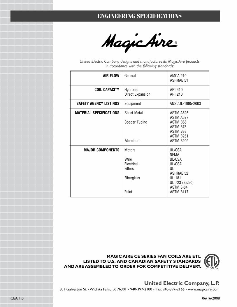
MAGIC AIRE CE SERIES FAN COILS ARE ETLLISTED TO U.S. AND CANADIAN SAFETY STANDARDS
AND ARE ASSEMBLED TO ORDER FOR COMPETITIVE DELIVERY.
EnginEEring SpEcificationS
United Electric Company designs and manufactures its Magic Aire products in accordance with the following standards:
WOLFRIA lareneG 102ACMA15EARHSA
YTICAPACLIOC cinordyHnoisnapxEtceriD
014IRA012IRA
SGNITSILYCNEGAYTEFAS Equipment ANSI/UL-1995-2003
SNOITACIFICEPSLAIRETAM lateMteehS
gnibuTreppoC
munimulA
525AMTSA725AMTSA
86BMTSA57BMTSA88BMTSA
152BMTSA902BMTSA
STNENOPMOCROJAM srotoM
eriWlacirtcelE
sretliF
ssalgrebiF
tniaP
ASC/LUAMEN
ASC/LUASC/LU
LU25EARHSA
181LU)05/52(327LU
48-EMTSA711BMTSA
CEA 1.0 06/16/2008
Recommended