PROCESS MODELING THE SUPERPLASTIC FORMING BEHAVIOR OF INCONEL ALLOY 718SPF
BY
Gaylord D. Smith and Stanley R. Gregory Into Alloys International, Inc.
3200 Riverside Drive Huntington, WV 257051771
and
Yan Ma, Yong Li and Terence G. Langdon Departments of Materials Science and Mechanical Engineering
University of Southern California Los Angeles, CA 90089-1453
ABSTRACT
For aerospace design engineers to adopt INCONEL” alloy 718SPF” as a material for engine and airframe construction utilizing superplastic forming to produce the components, it is important to characterize both the process and the subsequent alloy’s characteristics. This paper seeks to show the compatibility of alloy 718SPF to current superplastic forming practice and equipment and to provide processing parameters as well as post forming microstructures.
Alloy 718SPF flow stress versus strain data were obtained at 954°C for varying strain rates and the data used to calculate “ml’ values (a measure of strain rate sensitivity). Flow stress is seen to decrease with decreasing strain rate. Also, grain size stability over the temperature range 927°C to 982°C is established.
Alloy 718SPF, as is typical of all nickel-base alloys, is prone to cavitation. Data for the number of cavities and the overall percentage area of cavitation as a function of true strain for several strain rates were determined using an image analysis software package and the results presented. Also under similar conditions, the average roundness coefficient (a measure of cavity growth by diffusion) and the cavity angle distribution are computed for various strain rates. Parameters for reducing cavitation based on the use of back pressure and total strain limits are also presented.
INCONEL and 718SPF are trademarks of the Into group of companies.
Superalloys 718,625,706 and Various Derivatives Edited by E.A. Loria
The Minerals, Metals &Materials Society, 1997
303
Introduction
There is a need for complex shaped parts for commercial and military aircraft applications which requires high nickel alloys to withstand a combination of high temperature, hot gas corrosion and high stress. Conventional methods of fabricating these components can require extensive welding and fabrication methods resulting in higher than desired costs and excessive part inventories. Superplastic forming, now highly sophisticated and used extensively for producing titanium and aluminum alloy aircraft parts, would be an ideal solution for producing nickel alloy components as well. However, for this to occur, a minimum level of technology must exist for an alloy which both meets the technical requirements of the end-use and is amenable to the superplastic forming practices and equipment now in commercial use. This paper seeks to show the applicability of alloy 718SPF to this manufacturing method by describing the superplastic forming characteristics of this alloy and the microstructure of the finished part. The merits of alloy 718 for commercial and military aircraft airframe and engine components have been long established and are widely known.
Combining superplastic forming capabilities with the properties of alloy 718SPF opens up major opportunities for engine design improvements and production economics. This combination will help gas turbine engine manufacturers create part designs that are not currently feasible. Superplastic forming has the unique capability to allow the manufacture of large, complex and detailed parts, thus combining many small parts. This increases part integrity by minimizing joining and joining problems, and reduces tooling costs and inventory complexities. Most importantly, superplastic forming of alloy 718SPF allows designers to fabricate components, now made with aluminum or titanium alloys, that meet higher strength, fatigue and temperature requirements.
INCONEL allov 718SPF Characteristics
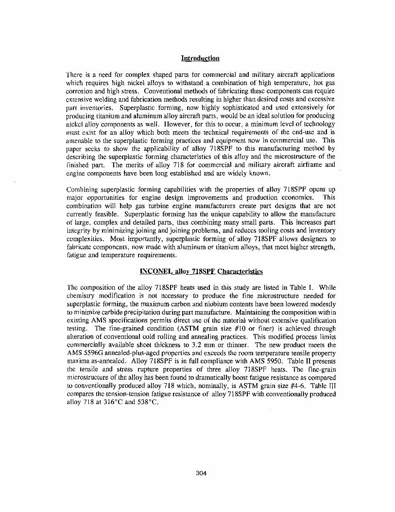
The composition of the alloy 718SPF heats used in this study are listed in Table I. While chemistry modification is not necessary to produce the fine microstructure needed for superplastic forming, the maximum carbon and niobium contents have been lowered modestly to minimize carbide precipitation during part manufacture. Maintaining the composition within existing AMS specifications permits direct use of the material without extensive qualification testing. The fine-grained condition (ASTM grain size #lO or finer) is achieved through alteration of conventional cold rolling and annealing practices. This modified process limits commercially available sheet thickness to 3.2 mm or thinner. The new product meets the AMS 5596G annealed-plus-aged properties and exceeds the room temperature tensile property maxima as-annealed. Alloy 718SPF is in full compliance with AMS 5950. Table II presents the tensile and stress rupture properties of three alloy 718SPF heats. The fine-grain microstructure of the alloy has been found to dramatically boost fatigue resistance as compared to conventionally produced alloy 718 which, nominally, is ASTM grain size #4-6. Table III compares the tension-tension fatigue resistance of alloy 718SPF with conventionally produced alloy 718 at 316°C and 538°C.
304
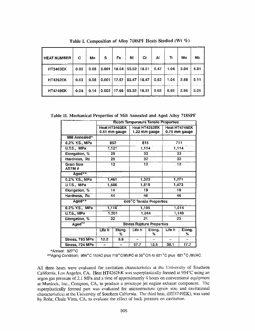
Table I. Composition of Alloy 718SPF Heats Studied (Wt %)
HT4262EK 0.03 0.08 0.001 17.97 53.47 18.47 0.52 1.04 2.88 5.11
HT4749EK 0.04 0.14 0.002 17.66 53.32 18.31 0.65 0.95 2.96 5.05
Table II. Mechanical Properties of Mill Annealed and Aged Alloy 718SPI
*Anneal: 927“C **Aging Condition: 954’C Ih/AC plus 719’C/8h/FC at 56’C/h to 621 “C plus 621 ‘C /8h/AC.
All three heats were evaluated for cavitation characteristics at the University of Southern California, Los Angeles, CA. Heat HT4262EK was super-plastically formed at 954°C using an argon gas pressure of 2.1 MPa and a time of approximately 4 hours on conventional equipment at Murdock, Inc., Compton, CA, to produce a prototype jet engine exhaust component. The superplastically formed part was evaluated for microstructure (grain size and cavitational characteristics) at the University of Southern Calfornia. The third heat, (HT4749EK), was used by Rohr, Chula Vista, CA, to evaluate the effect of back pressure on cavitation.
305
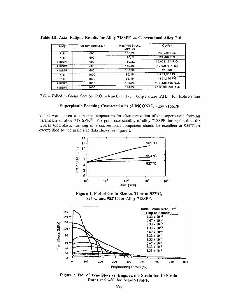
Table III. Axial Fatigue Results for Alloy 718SPF vs. Conventional Alloy 718.
F.G. = Failed in Gauge Section R.O. = Run Out Tab = Grip Failure P.H. = Pin Hole Failure
Superplastic Forming Characteristics of INCONEL alloy 718SPF
954°C was chosen as the aim temperature for characterization of the super-plastic forming parameters of alloy 718 SPF. (‘) The grain size stability of alloy 718SPF during the time for typical super-plastic forming of a conventional component should be excellent at 954°C as exemplified by the grain size data shown in Figure I.
14 12
r 10 t 8 i? 6 g 4 s 2
0 I
Time (set)
Figure 1. Plot of Grain Size vs. Time at 927”C, 954°C and 982°C for Alloy 718SPF.
160
140
3 120
g loo 1.33 x 10⁻³ 2 6.67 x lOA c 80 3.33 x 10⁴ ci 133 x 10-4
fz 60 40 6.67 3.33 x x 1O-5 IO-5
20 0
0 100 200 300 400 500 600 700 800
Engineering Strain (%)
Figure 2. Plot of True Stess vs. Engineering Strain for 10 Strain Rates at 954°C for Alloy 718SPF.
306
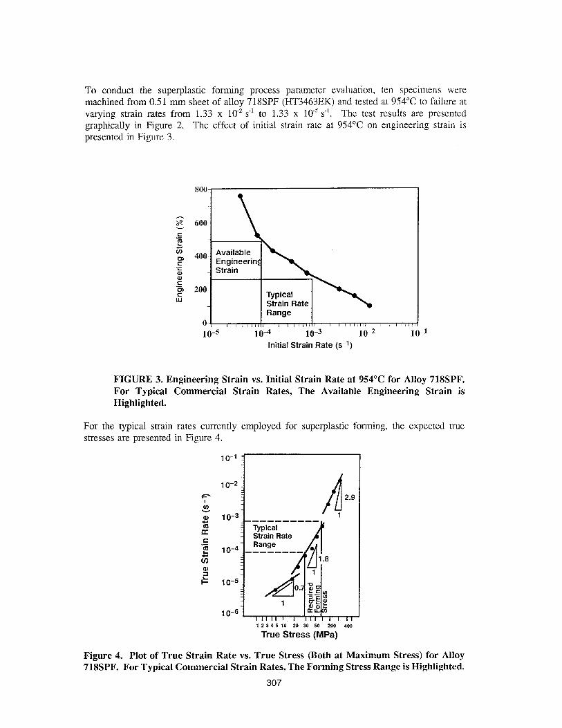
To conduct the superplastic forming process parameter evaluation, ten specimens were machined from 0.51 mm sheet of alloy 718SPF (HT3463EK) and tested at 954°C to failure at varying strain rates from 1.33 x lO-‘s-’ to 1.33 x 10m5 s-l. The test results are presented graphically in Figure 2. The effect of initial strain rate at 954°C on engineering strain is presented in Figure 3.
10-5 10-4 10-j 10-Z 10-l Initial Strain Rate (s-l)
FIGURE 3. Engineering Strain vs. Initial Strain Rate at 954°C for Alloy 718SPF. For Typical Commercial Strain Rates, The Available Engineering Strain is Highlighted.
For the typical strain rates currently employed for super-plastic forming, the expected true stresses are presented in Figure 4.
Range o- j , /(,,{, / , /,(/,I , , ,,//,I/
2.9
Figure 4. Plot of True Strain Rate vs. True Stress (Both at Maximum Stress) for Alloy 718SPF. For Typical Commercial Strain Rates, The Forming Stress Range is Highlighted.
307
True Stress (MPa)
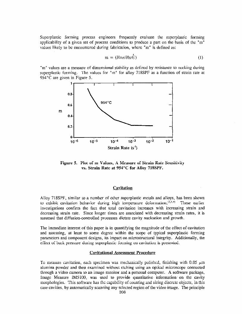
Superplastic forming process engineers frequently evaluate the superplastic forming applicability of a given set of process conditions to produce a part on the basis of the “m” values likely to be encountered during fabrication, where “m” is defined as:
m = @ln&lni) (1)
“rn’ values are a measure of dimensional stability as defined by resistance to necking during superplastic forming. The values for “m” for alloy 71 SSPF as a function of strain rate at 954°C are given in Figure 5.
1
0.8
0.6
m 0.4
0.2
0
I I I I
1 o-5 1 o-4 10-3
Strain Rate (s-l)
10-2 11
-
-
~
-
O-1
Figure 5. Plot of m Values, A Measure of Strain Rate Sensitivity vs. Strain Rate at 954°C for Alloy 718SPF.
Cavitation
Alloy 718SPF, similar to a number of other superplastic metals and alloys, has been shown to exhibit cavitation behavior during high temperature deformation.(2*3*4) These earlier investigations confirm the fact that total cavitation increases with increasing strain and decreasing strain rate. Since longer times are associated with decreasing strain rates, it is assumed that diffusion-controlled processes dictate cavity nucleation and growth.
The immediate interest of this paper is in quantifying the magnitude of the effect of cavitation and assessing, at least to some degree within the scope of typical superplastic forming parameters and component designs, its impact on microstructural integrity. Additionally, the effect of back pressure during superplastic forming on cavitation is presented.
Cavitational Assessment Procedure
To measure cavitation, each specimen was mechanically polished, finishing with 0.05 pm alumina powder and then examined without etching using an optical microscope connected through a video camera to an image monitor and a personal computer. A software package, Image Measure IM5100, was used to provide quantitative information. on the cavity morphologies. This software has the capability of counting and sizing discrete objects, in this case cavities, by automatically scanning any selected region of the video image. The principle
308
of operation is that each cavity is outlined and measured, and when the entire region, termed the measurement window, has been scanned, the computer automatically calculates and provides quantitative information on the extent and the morphology of the cavitation.
In the present investigation, about 500 windows were measured for each specimen. The following parameters were obtained: (1) the total number of cavities within approximately 500 measurement windows, (2) the cavity size distribution in terms of area, (3) the orientation of each cavity, defined as the angle between the maximum diameter and the tensile axis and (4) a roundness coefficient for each cavity, defined as 4aArea/(Perimeter)‘, where a value of 1 defines a perfect circle and values less than 1 defines a deviation from a circle.
PrototvDe ComDonent Evaluation
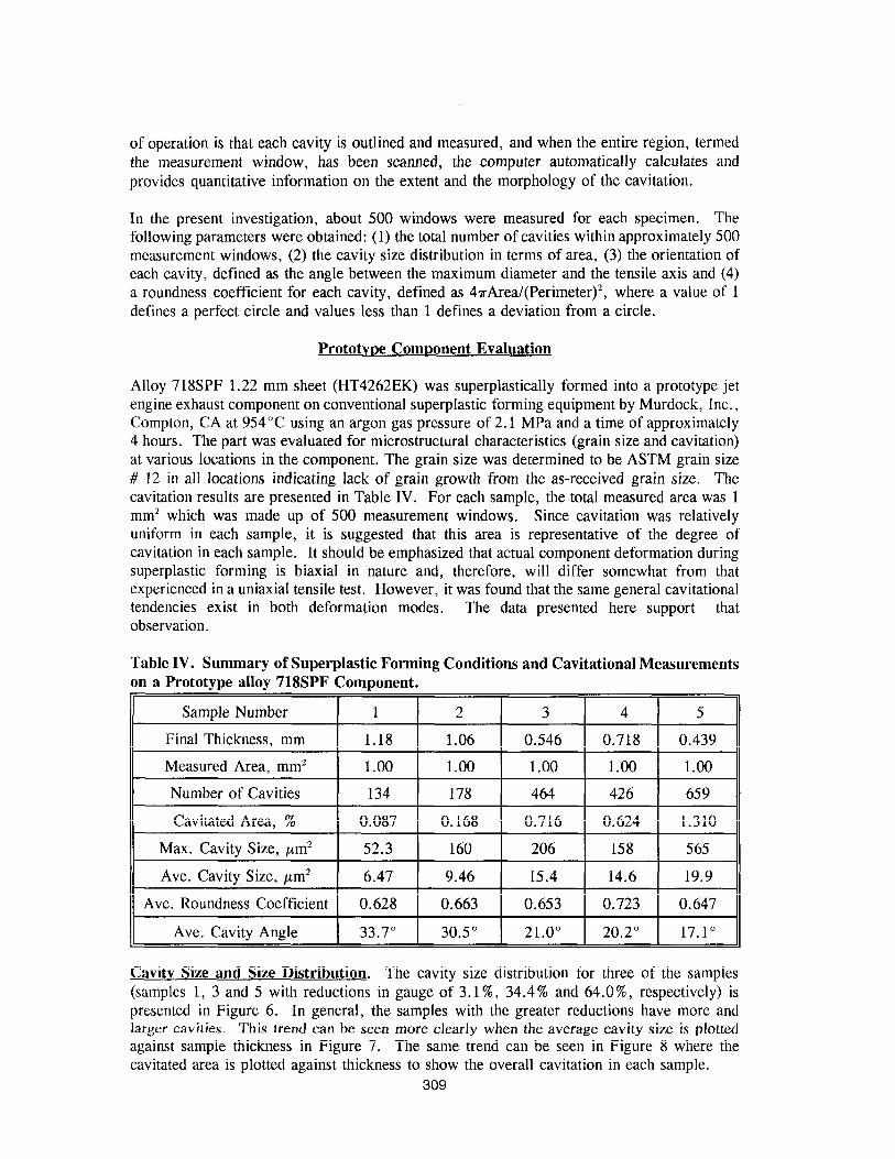
Alloy 718SPF 1.22 mm sheet (HT4262EK) was superplastically formed into a prototype jet engine exhaust component on conventional superplastic forming equipment by Murdock, Inc., Compton, CA at 954°C using an argon gas pressure of 2.1 MPa and a time of approximately 4 hours. The part was evaluated for microstructural characteristics (grain size and cavitation) at various locations in the component. The grain size was determined to be ASTM grain size # 12 in all locations indicating lack of grain growth from the as-received grain size. The cavitation results are presented in Table IV. For each sample, the total measured area was 1 mm2 which was made up of 500 measurement windows. Since cavitation was relatively uniform in each sample, it is suggested that this area is representative of the degree of cavitation in each sample. It should be emphasized that actual component deformation during superplastic forming is biaxial in nature and, therefore, will differ somewhat from that experienced in a uniaxial tensile test. However, it was found that the same general cavitational tendencies exist in both deformation modes. The data presented here support that observation.
Table IV. Summary of Superplastic Forming Conditions and Cavitational Measurements on a Prototype alloy 718SPF Component.
II Ave. Cavity Angle
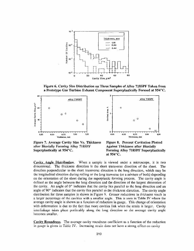
Cavitv Size and Size Distribution. The cavity size distribution for three of the samples (samples 1, 3 and 5 with reductions in gauge of 3.1%, 34.4% and 64.0%, respectively) is presented in Figure 6. In general, the samples with the greater reductions have more and larger cavities. This trend can be seen more clearly when the average cavity size is plotted against sample thickness in Figure 7. The same trend can be seen in Figure 8 where the cavitated area is plotted against thickness to show the overall cavitation in each sample.
309
Thickness, mm
0 20 40 60 80
Cavity Size, pm2
Figure 6. Cavity Size Distribution on Three Samples of Alloy 718SPF Taken from a Prototype Gas Turbine Exhaust Component Superplastically Formed at 954°C.
30
alloy 718SPF
n
Figure 7. Average Cavity Size Vs. Thickness after Biaxially Forming Alloy 71SSPF Superplastically at 954” C.
2
alloy 716SPF
Figure 8. Percent Cavitation Plotted Against Thickness after Biaxially Forming Alloy 718SPF Superplastically at 954°C.
Cavitv Anple Distribution. When a sample is viewed under a microscope, it is two dimensional. The thickness direction is the short transverse direction of the sheet. The direction perpendicular to the short transverse direction is the long direction, which may be the longitudinal direction during rolling or the long tranverse (or a mixture of both) depending on the orientation of the sheet during the superplastic forming process. The cavity angle is defined as the angle between the long direction and the direction of the largest dimension of the cavity. An angle of 0” indicates that the cavity lies parallel to the long direction and an angle of 90” indicates that the cavity lies parallel to the thickness direction. The cavity angle distribution for three samples is shown in Figure 9. Greater reductions in thickness result in a larger percentage of the cavities with a smaller angle. This is seen in Table IV where the average cavity angle is shown as a function of reduction in gauge. This change of orientation with deformation is due to the fact that more cavities link when the strain is larger. Cavity interlinkage takes place preferably along the long direction so the average cavity angle becomes smaller.
Cavitv Roundness. The average cavity roundness coefficient as a function of the reduction in gauge is given in Table IV. Increasing strain does not have a strong effect on cavity
310
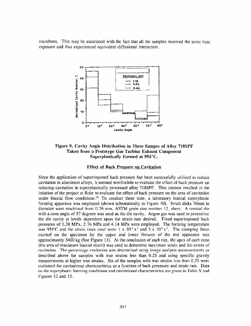
roundness. This may be associated with the fact that all the samples received the same time exposure and thus experienced equivalent diffusional interaction.
00 15” 30” 450 60” 75” 90’
Cavity Angie
Figure 9. Cavity Angle Distribution in Three Sampes of Alloy 718SPF Taken from a Prototype Gas Turbine Exhaust Component
Superplastically Formed at 954°C.
Effect of Back Pressure on Cavitation
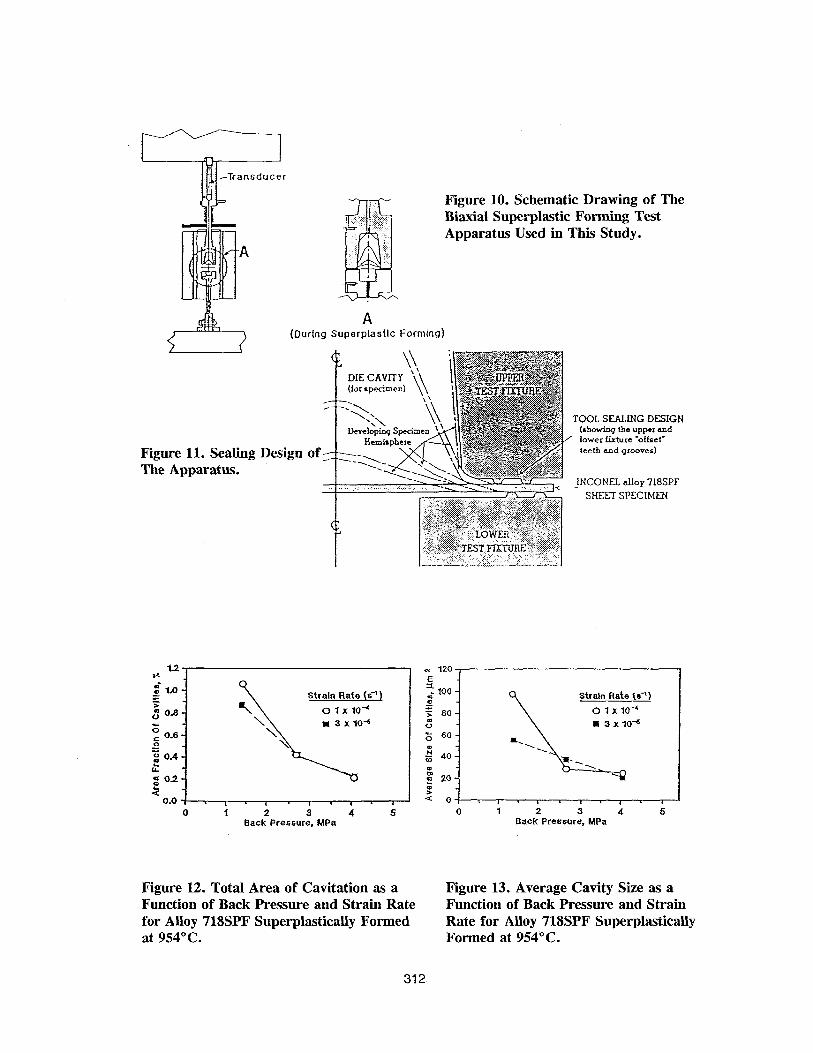
Since the application of superimposed back pressure has been successfully utilized to reduce cavitation in aluminum alloys, it seemed worthwhile to evaluate the effect of back pressure on reducing cavitation in superplastically processed alloy 718SPF. This interest resulted in the initation of the project at Rohr to evaluate the effect of back pressure on the area of cavitation under biaxial flow conditions. w To conduct these tests, a laboratory biaxial superplastic forming apparatus was employed (shown schematically in Figure 10). Small disks 76mm in diameter were machined from 0.76 mm, ASTM grain size number 12, sheet. A conical die with a cone angle of 57 degrees was used as the die cavity. Argon gas was used to pressurize the die cavity at levels dependent upon the strain rate desired. Fixed superimposed back pressures of 1.38 MPa, 2.76 MPa and 4.14 MPa were employed. The forming temperature was 954°C and the strain rates used were 1 x lOA s’ and 3 x 10⁻⁵s~‘. The clamping force exerted on the specimen by the upper and lower fixtures of the test apparatus was approximately 3400 kg (See Figure 11). At the conclusion of each run, the apex of each cone (the area of maximum biaxial strain) was used to determine maximum strain and the extent of cavitation. The percentage cavitation was determined using image analysis measurements as described above for samples with true strains less than 0.25 and using specific gravity measurements at higher true strains. Six of the samples with true strains less than 0.25 were evaluated for cavitational characteristics as a function of back presssure and strain rate. Data on the super-plastic forming conditions and cavitational characteristics are given in Table V and Figures 12 and 13.
311
Transducer
Figure 11. Sealing The Apparatus.
Design
Figure 10. Schematic Drawing of The Biaxial Superplastic Feting Test Apparatus Used in This Study.
A (During Superplasllc Forming)
I DIE CAVITY (for Ppe.imen)
TOOL SEALING DESIGN (shodnq the upper and
’ lower fixture -offset’ teeth and grooves)
JNCONEL alloy 718SPF
SHEET SPECIMEN
Strain Rate (s-‘l
0 1 2 3 4 5 Back Pressure, MPa
Strain Rate (C’)
01x10~
m 3x10”
0 1 2 3 4 5 Back Pressure, MPa
Figure 12. Total Area of Cavitation as a Figure 13. Average Cavity Size as a Function of Back Pressure and Strain Rate Function of Back Pressure and Strain for Alloy 718SPF Superplastically Formed Rate for Alloy 718SPF Superplastically at 954°C. Formed at 954°C.
312
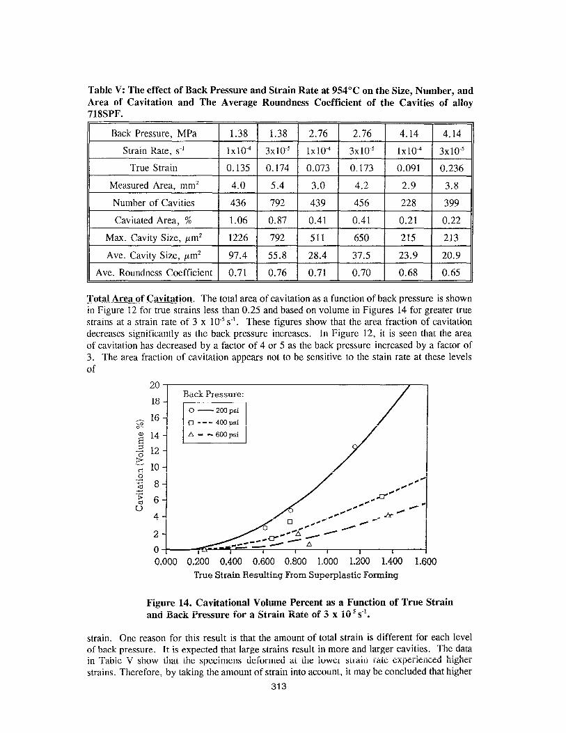
Table V: The effect of Back Pressure and Strain Rate at 954°C on the Size, Number, and Area of Cavitation and The Average Roundness Coefficient of the Cavities of alloy 718SPF.
Max. Cavity Size, pm*
Ave. Cavity Size, pm* 97.4 55.8 28.4 37.5 23.9 20.9
Ave. Roundness Coefficient 0.71 0.76 0.71 0.70 0.68 0.65
Total Area of Cavitation. The total area of cavitation as a function of back pressure is shown in Figure 12 for true strains less than 0.25 and based on volume in Figures 14 for greater true strains at a strain rate of 3 x 10e5 s’. These figures show that the area fraction of cavitation decreases significantly as the back pressure increases. In Figure 12, it is seen that the area of cavitation has decreased by a factor of 4 or 5 as the back pressure increased by a factor of 3. The area fraction of cavitation appears not to be sensitive to the stain rate at these levels of
20
18
2
0 0.000 0.200 0.400 0.600 0.800 1.000 1.200 1.400 1.600
True Strain Resulting From Superplastic Forming
Figure 14. Cavitational Volume Percent as a Function of True Strain and Back Pressure for a Strain Rate of 3 x 10m5s”.
strain. One reason for this result is that the amount of total strain is different for each level of back pressure. It is expected that large strains result in more and larger cavities. The data in Table V show that the specimens deformed at the lower strain rate experienced higher strains. Therefore, by taking the amount of strain into account, it may be concluded that higher
313
strain rates lead to less total areas of cavitation. This is the same conclusion found in the uniaxial tensile tests conducted without the use of back pressure.
7. The average size of cavities as a function of back pressure is illustrated in Figure 13. It is evident that the average cavity size decreases as the back pressure increases and that the strain rate appears to have no significant effect on the average cavity size. From Table V, it appears that there is a trend toward smaller cavities at slower strain rates. Considering that the area fractions of cavities are almost the same for each pair of back pressure samples, the cavity density must become greater with decreasing strain rate.
1.
2.
3.
4.
5.
1.
2.
3.
4.
5.
Conclusions
Alloy 718SPF can be produced with an ASTM grain size #lO or smaller and subsequently super-plastically formed at 954°C using an argon gas pressure of 2.1 MPa. Total elongation increases and forming stresses decrease markedly with decreasing strain rate and increasing temperature.
The alloy retains its original tensile properties after super-plastic forming through strains up to approximating 200% and achieves AMS 5596G annealed plus aged tensile properties through standard aging heat treatments.
Under biaxial strain conditions, the amount of cavitation increases in total area and average cavity size with increasing deformation.
Under biaxial strain conditions, cavity interlinkage is generally perpendicular to the thickness direction thus reducing the average cavity angle as the amount of deformation is increased.
The imposition of a back pressure results in a significant reduction in total area of cavitation and average cavity size.
References
M. W. Mahoney, “Superplastic Properties of INCONEL alloy 718” (Paper presented at the International Symposium on the Metallurgy and Applications of INCONEL alloy 718, Pittsburgh, PA, June 1989, published by ASM).
B. P. Kashyap and A. K. Mukherjee, Reseach Mechanics, 17 (1986), 293.
J. Pilling and N. Ridley, Reseach Mechanics, 23 (1988), 31.
X. G. Jiang, J. C. Earthman and F. S. Mohamed, Journal of Materials Science, 29 (1994), 5499.
R. B. LeHolm and J. D. Bhatt, “Effects of Back Pressure in Suppressing Cavitation in INCONEL alloy 718SPF” (Final Report: Contract No. 110989, June 1996).
314
Recommended