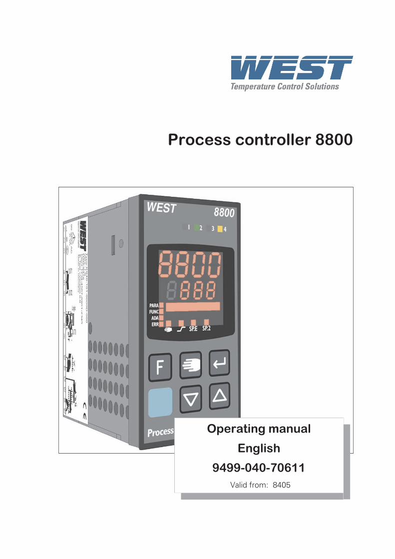
Process controller 8800
Operating manual
English
9499-040-70611
Valid from: 8405
© West Instruments • Printed in GermanyAll rights reserved. No part of this document may bereproduced or published inany form or by any means without prior written permission from the copyrightowner.A publication of West Instruments, The Hyde Business Park,Brighton BN2 4JU, England
8800/8840 Configurator
More efficiency in engineering, more overview in operating:The projecting environment for the West controllers 8800/8840
Description of symbols:
g General information
a General warning
l Attention: ESD sensitive devices
ATTENTION!
Mini V
ersion
andUpdate
s on
www.westi
nstrum
ents.co
m
8800 process controller 3
Contents
1 Mounting . . . . . . . . . . . . . . . . . . . . . . . . . . . . . . 6
2 Electrical connections . . . . . . . . . . . . . . . . . . . . . . . 7
2.1 Connecting diagram . . . . . . . . . . . . . . . . . . . . . . . 7
2.2 Terminal connection. . . . . . . . . . . . . . . . . . . . . . . . . 8
3 Operation . . . . . . . . . . . . . . . . . . . . . . . . . . . . . 12
3.1 Front view . . . . . . . . . . . . . . . . . . . . . . . . . . . . 12
3.2 Behaviour after power-on . . . . . . . . . . . . . . . . . . . . . 13
3.3 Operating level . . . . . . . . . . . . . . . . . . . . . . . . . . . 13
3.4 Error list / Mainenance manager . . . . . . . . . . . . . . . . . 14
3.5 Self-tuning . . . . . . . . . . . . . . . . . . . . . . . . . . . . . 17
3.5.1 Preparation for self-tuning . . . . . . . . . . . . . . . . . . . . . . . 17
3.5.2 Optimization after start-up or at the set-point . . . . . . . . . . . . . . 18
3.5.3 Selecting the method ( ConF/ Cntr/ tunE) . . . . . . . . . . . . . 18
3.5.4 Self-tuning start . . . . . . . . . . . . . . . . . . . . . . . . . . . . . 22
3.5.5 Self-tuning cancellation . . . . . . . . . . . . . . . . . . . . . . . . 22
3.5.6 Acknowledgement procedures in case of unsuccessful self-tuning . 23
3.5.7 Examples for self-tuning attempts . . . . . . . . . . . . . . . . . . 24
3.6 Manual self-tuning . . . . . . . . . . . . . . . . . . . . . . . . . 25
3.7 Second PID parameter set . . . . . . . . . . . . . . . . . . . . . 26
3.8 Alarm handling. . . . . . . . . . . . . . . . . . . . . . . . . . . 27
3.9 Operating structure . . . . . . . . . . . . . . . . . . . . . . . . . 29
4 Configuration level . . . . . . . . . . . . . . . . . . . . . . . . 30
4.1 Configuration survey . . . . . . . . . . . . . . . . . . . . 30
4.2 Configuration parameters . . . . . . . . . . . . . . . . . . . . 31
4.3 Set-point processing . . . . . . . . . . . . . . . . . . . . . . . . 49
4.3.1 Set-point gradient / ramp . . . . . . . . . . . . . . . . . . . . . . . . 49
4.4 Switching behaviuor . . . . . . . . . . . . . . . . . . . . . . . . 50
4.4.1 Standard ( CyCl= 0 ) . . . . . . . . . . . . . . . . . . . . . . . . . 50
4.4.2 Switching attitude linear ( CyCl= 1 ) . . . . . . . . . . . . . . . . . 50
4.4.3 Switching attitude non-linear ( CyCl= 2 ) . . . . . . . . . . . . . . . 51
4.4.4 Heating and cooling with constant period ( CyCl= 3 ) . . . . . . . . 52
4 8800 process controller
4.5 Configuration examples . . . . . . . . . . . . . . . . . . . . . . 53
4.5.1 On-Off controller / Signaller (inverse) . . . . . . . . . . . . . . . . . 53
4.5.2 2-point controller (inverse) . . . . . . . . . . . . . . . . . . . . . . . 54
4.5.3 3-point controller (relay & relay) . . . . . . . . . . . . . . . . . . . . 55
4.5.4 3-point stepping controller (relay & relay) . . . . . . . . . . . . . . . 56
4.5.5 Continuous controller (inverse) . . . . . . . . . . . . . . . . . . . . . 57
4.5.6 ∆ - Y - Off controller / 2-point controller with pre-contact . . . . . . 58
4.5.7 8800 process controller with measured value output . . . . . . . . . . 59
4.5.8 Continuous controller with integrated positioner ( Cntr/ C.Fnc = 6 ) 60
5 Parameter setting level . . . . . . . . . . . . . . . . . . . . . . 61
5.1 Parameter survey . . . . . . . . . . . . . . . . . . . . . . . . 61
5.2 Parameters . . . . . . . . . . . . . . . . . . . . . . . . . . . . . 62
5.3 Input scaling . . . . . . . . . . . . . . . . . . . . . . . . . . . . 65
5.3.1 Input Inp.1 and InP.3 . . . . . . . . . . . . . 65
5.3.2 Input InP.2. . . . . . . . . . . . . . . . . . . . . . . . . . . . . . . 66
6 Calibration level . . . . . . . . . . . . . . . . . . . . . . . . . 67
7 Special functions . . . . . . . . . . . . . . . . . . . . . . . . . 70
7.1 DAC®– motor actuator monitoring . . . . . . . . . . . . . . . 70
7.2 O2 measurement . . . . . . . . . . . . . . . . . . . . . . . . . . 72
7.2.1 Connection . . . . . . . . . . . . . . . . . . . . . . . . . . . . . . . 72
7.2.2 Configuration: . . . . . . . . . . . . . . . . . . . . . . . . . . . . . . 73
7.3 Linearization . . . . . . . . . . . . . . . . . . . . . . . . . . . . 74
7.4 8800 process controller as Modbus master . . . . . . . . . . . . 75
8 8800/8840 configurator . . . . . . . . . . . . . . . . . . . . . . 76
9 Versions . . . . . . . . . . . . . . . . . . . . . . . . . . . . . . 77
10 Technical data . . . . . . . . . . . . . . . . . . . . . . . . . . 78
11 Safety hints . . . . . . . . . . . . . . . . . . . . . . . . . . . . 81
11.1 Resetting to factory setting. . . . . . . . . . . . . . . . . . . . . 82
12 Notes . . . . . . . . . . . . . . . . . . . . . . . . . . . . . . . . 83
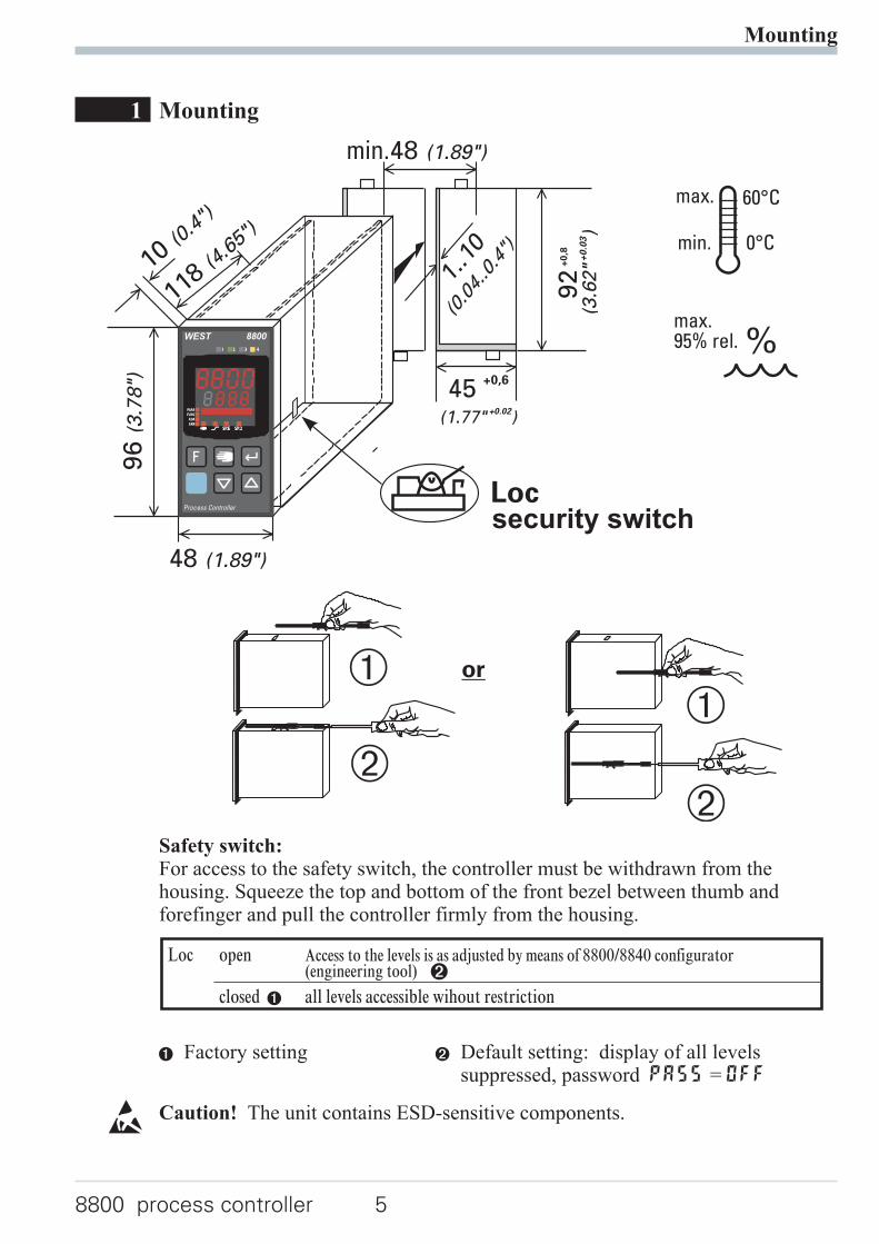
1 Mounting
Safety switch:For access to the safety switch, the controller must be withdrawn from thehousing. Squeeze the top and bottom of the front bezel between thumb andforefinger and pull the controller firmly from the housing.
1 Factory setting 2 Default setting: display of all levelssuppressed, password PASS = OFF
l Caution! The unit contains ESD-sensitive components.
Mounting
8800 process controller 5
or
%max.95% rel.
max. 60°C
0°Cmin.
96(3
.78")
48 (1.89")
Loc
min.48 (1.89")
10 (0.4
")
1..10
(0.04..0.4")
118 (4.6
5")
45 +0,6
(1.77" )+0.02
92+
0,8
(3.6
2"
)+
0.0
3
*
Ü
*
Ü
security switch
WEST 8800
Process Controller
Loc open Access to the levels is as adjusted by means of 8800/8840 configurator(engineering tool) 2
closed 1 all levels accessible wihout restriction
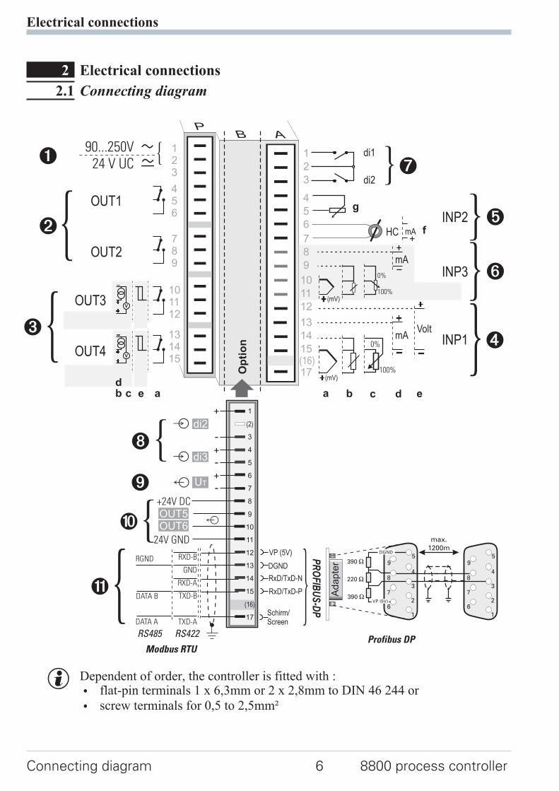
2 Electrical connections
2.1 Connecting diagram
g Dependent of order, the controller is fitted with :
w flat-pin terminals 1 x 6,3mm or 2 x 2,8mm to DIN 46 244 or
w screw terminals for 0,5 to 2,5mm²
Electrical connections
Connecting diagram 6 8800 process controller
1
3
4
5
6
7
8
9
10
11
12
13
14
15
17
(2)
(16)
mA
(mV)
(mV)
Volt
mA
INP2
INP3
INP1
di2
di1123
456
789
101112
131415
Op
tio
n
1
2
3
4
5
6
7
8
9
10
11
12
13
14
15
17(16)
OUT1
OUT2
OUT3
OUT4
90...250V
24 V UC
0%
100%
V
V
mAHC
di2
di3
UT
RXD-B
GND
RXD-A
TXD-B
TXD-A
RS485 RS422
Modbus RTU
RGND
DATA B
DATA A
9
0
8
3
2
17
6
5
4
a b c d e
f
g
ab cd
e
+24V DC
24V GND
OUT5OUT6
!
VP (5V)
DGND
RxD/TxD-N
RxD/TxD-P
PR
OF
IBU
S-D
P
Schirm/Screen
59
48
37
26
1
59
48
37
26
1
390 [
390 [
220 [
DGND
VP (5V)
max.1200m
Adapte
r
Profibus DP
2.2 Terminal connection
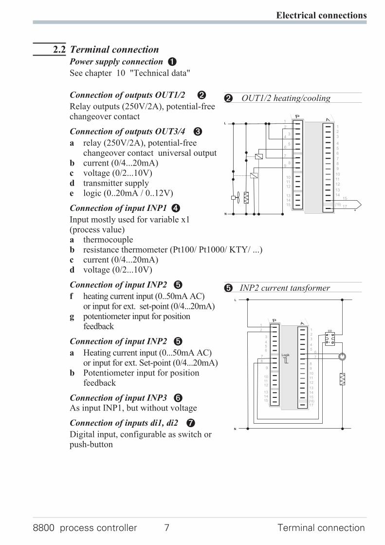
Power supply connection 1
See chapter 10 "Technical data"
Connection of outputs OUT1/2 2
Relay outputs (250V/2A), potential-freechangeover contact
Connection of outputs OUT3/4 3
a relay (250V/2A), potential-freechangeover contact universal output
b current (0/4...20mA)c voltage (0/2...10V)d transmitter supplye logic (0..20mA / 0..12V)
Connection of input INP1 4
Input mostly used for variable x1(process value)a thermocoupleb resistance thermometer (Pt100/ Pt1000/ KTY/ ...)c current (0/4...20mA)d voltage (0/2...10V)
Connection of input INP2 5
f heating current input (0..50mA AC)or input for ext. set-point (0/4...20mA)
g potentiometer input for positionfeedback
Connection of input INP2 5
a Heating current input (0...50mA AC)or input for ext. Set-point (0/4...20mA)
b Potentiometer input for positionfeedback
Connection of input INP3 6As input INP1, but without voltage
Connection of inputs di1, di2 7
Digital input, configurable as switch orpush-button
Electrical connections
8800 process controller 7 Terminal connection
6
9
101112
131415
1
2
3
4
5
6
7
8
9
10
11
12
13
14
17(16)
L
N
+
5
43
2
1
8
7
15
2 OUT1/2 heating/cooling
L
N
+
_SSR
3
456
9
101112
131415
1
2
3
4
5
8
9
10
11
12
13
14
15
17(16)
2
1
8
76
7Logik
5 INP2 current tansformer
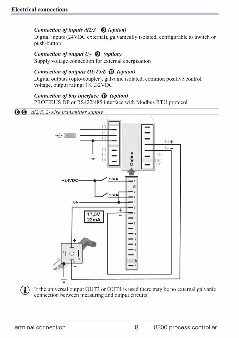
Connection of inputs di2/3 8 (option)
Digital inputs (24VDC external), galvanically isolated, configurable as switch orpush-button
Connection of output UT 9 (option)
Supply voltage connection for external energization
Connection of outputs OUT5/6 0 (option)
Digital outputs (opto-coupler), galvanic isolated, common positive controlvoltage, output rating: 18...32VDC
Connection of bus interface ! (option)
PROFIBUS DP or RS422/485 interface with Modbus RTU protocol
g If the universal output OUT3 or OUT4 is used there may be no external galvanicconnection between measuring and output circuits!
Electrical connections
Terminal connection 8 8800 process controller
131415
Op
tio
n
17(16)
1
3
4
5
6
7
8
9
10
11
12
13
14
15
17
(2)
(16)
+24VDC
5mA
5mA
0V
1
2
3
K
+
-
+-17,5V
22mA
14
13 +-
15
OUT3
10
11
12
J
J
89 di2/3, 2-wire transmitter supply
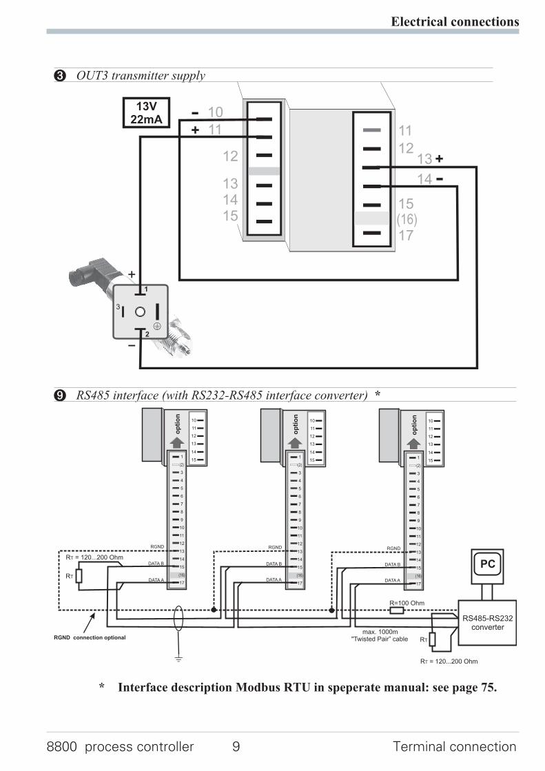
* Interface description Modbus RTU in speperate manual: see page 75.
Electrical connections
8800 process controller 9 Terminal connection
1
2
3
K
+
-
+
-
13V22mA
131415
11
1213
17(16)
14
15
12
11
10
3 OUT3 transmitter supply
1
3
4
5
6
7
8
9
10
11
12
13
14
15
17
(2)
(16)
op
tio
n
1
3
4
5
6
7
8
9
10
11
12
13
14
15
17
(2)
(16)
op
tio
n
1
3
4
5
6
7
8
9
10
11
12
13
14
15
17
(2)
(16)
op
tio
n
11
12
13
14
15
10
11
12
13
14
15
10
11
12
13
14
15
RGND RGND RGND
RT
RS485-RS232converter
PC
DATA A
DATA B
DATA A
DATA B
DATA A
DATA B
J
max. 1000m"Twisted Pair” cable
10
RT
R=100 Ohm
RGND connection optional
R = 120...200 OhmT
R = 120...200 OhmT
9 RS485 interface (with RS232-RS485 interface converter) *
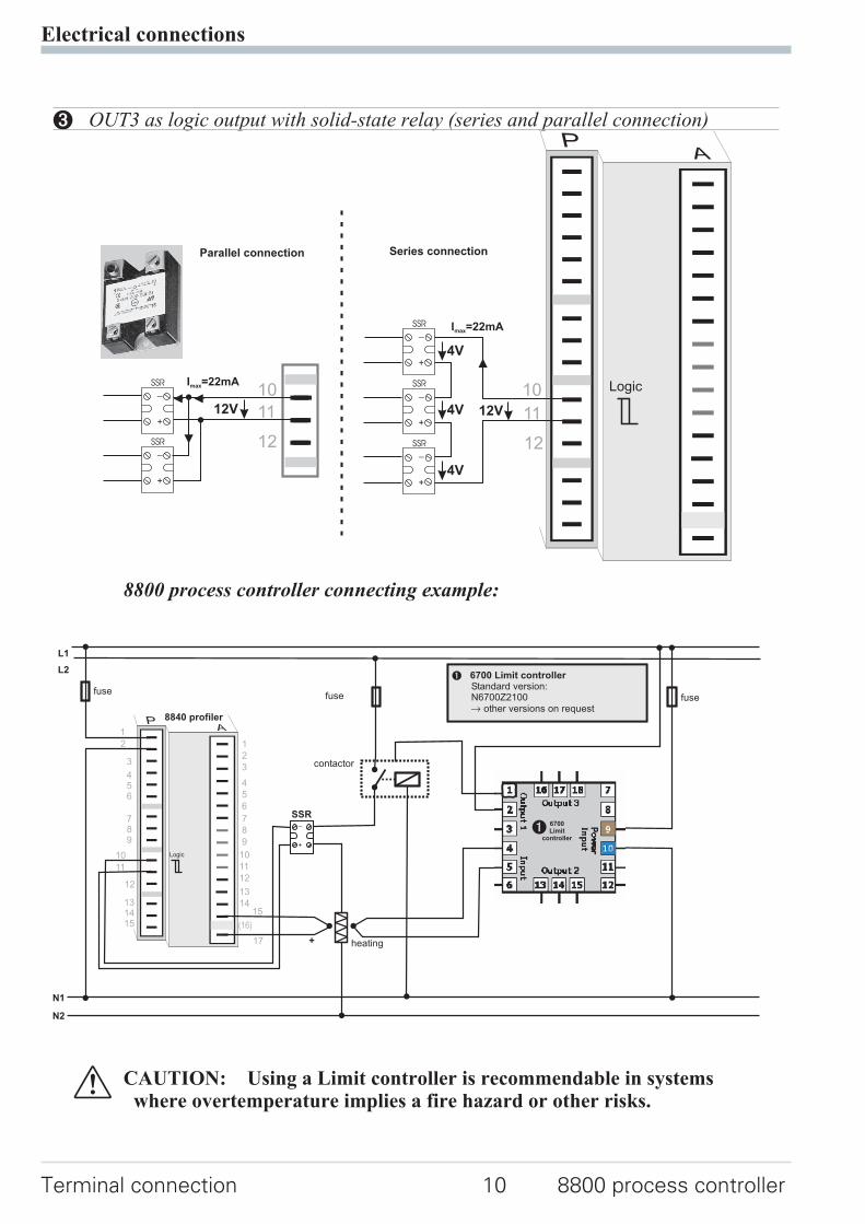
8800 process controller connecting example:
a CAUTION: Using a Limit controller is recommendable in systemswhere overtemperature implies a fire hazard or other risks.
Electrical connections
Terminal connection 10 8800 process controller
12
+
_SSR
+
_SSR
+
_SSR
Series connectionParallel connection
+
_SSR
+
_SSR
4V
4V
4V 12V
I =22mAmax
I =22mAmax
12V 11
1010
11
12
Logic
3 OUT3 as logic output with solid-state relay (series and parallel connection)
+
_
L1
L2
N1
N2
fusefuse fuse
SSR
contactor
heating+
3
456
789
11
131415
1
2
3
4
5
6
7
8
9
10
11
12
13
14
17
(16)
15
2
1
12
10 Logic
8840 profiler
1
N6700Z21
6700 Limit controllerStandard version:
00other versions on requestr
6700Limit
controller
1
3 Operation
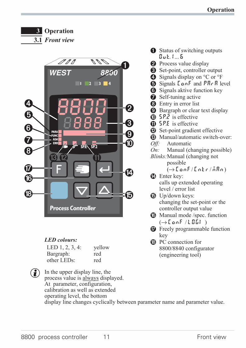
3.1 Front view
LED colours:
LED 1, 2, 3, 4: yellowBargraph: redother LEDs: red
g In the upper display line, theprocess value is always displayed.At parameter, configuration,calibration as well as extendedoperating level, the bottomdisplay line changes cyclically between parameter name and parameter value.
Operation
8800 process controller 11 Front view
(
1
2
3
4
5
6
$
78
%
&
(
/
6
778
3
4
5
90
§" !§""
1 Status of switching outputsOuT.1... 6
2 Process value display
3 Set-point, controller output
4 Signals display on °C or °F
5 Signals ConF and PArA level
6 Signals aktive function key
7 Self-tuning active
8 Entry in error list
9 Bargraph or clear text display
0 SP.2 is effective
! SP.E is effective
" Set-point gradient effective
§ Manual/automatic switch-over:Off: AutomaticOn: Manual (changing possible)Blinks:Manual (changing not
possible
(r ConF/ Cntr/ MAn)
$ Enter key:calls up extended operatinglevel / error list
% Up/down keys:changing the set-point or thecontroller output value
& Manual mode /spec. function
(→ ConF / LOGI )
/ Freely programmable functionkey
( PC connection for8800/8840 configurator(engineering tool)
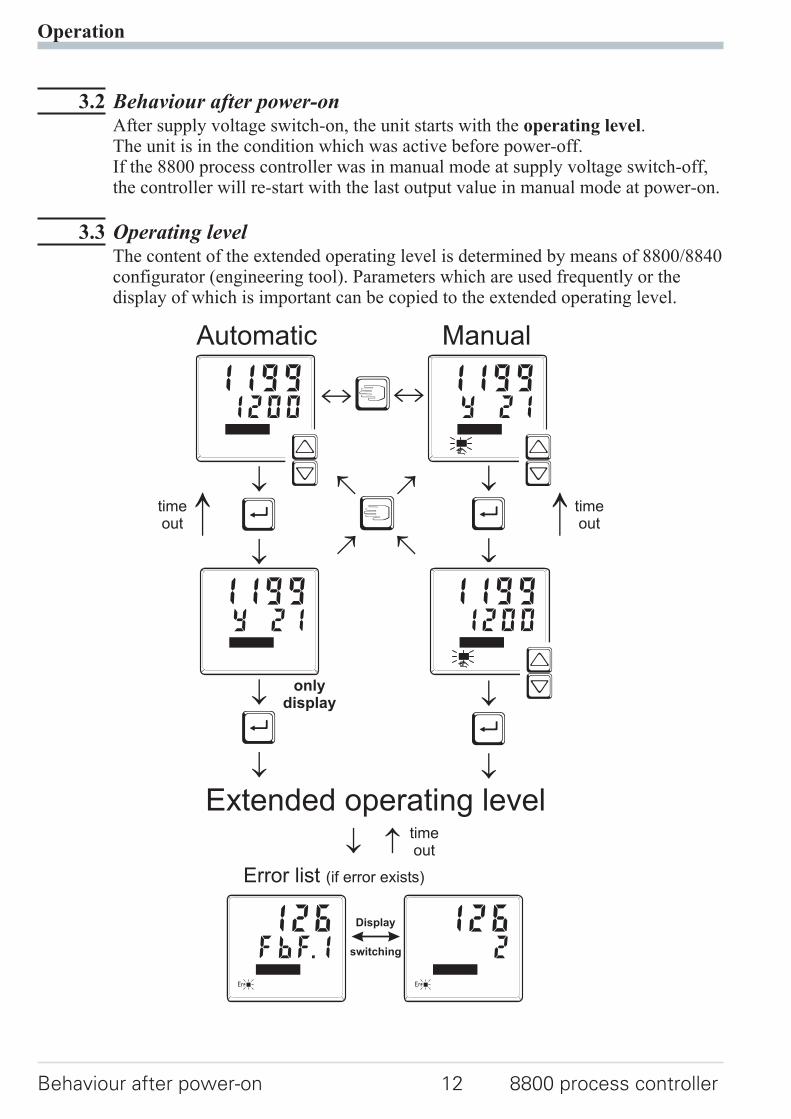
3.2 Behaviour after power-onAfter supply voltage switch-on, the unit starts with the operating level.The unit is in the condition which was active before power-off.If the 8800 process controller was in manual mode at supply voltage switch-off,the controller will re-start with the last output value in manual mode at power-on.
3.3 Operating levelThe content of the extended operating level is determined by means of 8800/8840configurator (engineering tool). Parameters which are used frequently or thedisplay of which is important can be copied to the extended operating level.
Operation
Behaviour after power-on 12 8800 process controller
Ò
ÒÙ
Ù
Ù
Ù
Automatic
Extended operating level
Manual
ii
onlydisplay
switching
Display
Error list (if error exists)
Y 211199
12001199
ÈÌ
ÈÌ
Y 211199
12001199
ÈÌ
FbF.1126
Err
2126
Err
timeout
timeout
timeout
3.4 Error list / Mainenance managerWith one or several errors, the extended operating levelalways starts with the error list. Signalling an actual entryin the error list (alarm, error) is done by the Err LED in the
display. To reach the error list press Ù twice.
Error list:
Operation
8800 process controller 13 Error list / Mainenance manager
°C°F
Err LED status Signification Proceed as followsblinks
(status2)Alarm due to existingerror
- Determine the error type in the error list- After error correction the unit changes to status1
lit(status1)
Error removed, alarmnot acknowledged
- Acknowledge the alarm in the error list pressing key ÈorÌ- The alarm entry was deleted (status0).
off(status0)
No error, all alarmentries deleted
- -Not visible except when acknowledging
Name Description Reason Possible remedial actionE.1 Internal error,
cannot be removed- E.g. defective EEPROM - Contact West service
- Return unit to our factoryE.2 Internal error, can be
reset- e.g. EMC trouble - Keep measurement and power supply
cables in separate runs- Ensure that interference suppression
of contactors is providedE.3 Configuration error,
can be reset- wrong configuration- missing configuration
- Check interaction of configuration /parameters
E.4 Hardware error - Codenumber andhardware are notidentical
- Contact West service- Elektronic-/Optioncard must be
exchangedFbF.1 Sensor break INP1 - Sensor defective
- Faulty cabling- Replace INP1 sensor- Check INP1 connection
Sht.1 Short circuit INP1 - Sensor defective- Faulty cabling
- Replace INP1 sensor- Check INP1 connection
POL.1 INP1polarity error - Faulty cabling - Reverse INP1 polarityFbF.2 Sensor break INP2 - Sensor defective
- Faulty cabling- Replace INP2 sensor- Check INP2 connection
Sht.2 Short circuit INP2 - Sensor defective- Faulty cabling
- Replace sensor INP2- Check INP2 connection
POL.2 INP2 polarity - Faulty cabling - Reverse INP2 polarityFbF.3 Sensor break INP3 - Sensor defective
- Faulty cabling- Replace INP3 sensor- Check INP3 connection
Sht.3 Short circuit INP3 - Sensor defective- Faulty cabling
- Replace sensor INP3- Check INP3 connection
POL.3 INP3 polarity - Faulty cabling - Reverse INP3 polarity
Operation
Error list / Mainenance manager 14 8800 process controller
Name Description Reason Possible remedial actionHCA Heating current
alarm (HCA)- Heating current circuit
interrupted, I< HC.A orI>HC.A (dependent ofconfiguration)
- Heater band defective
- Check heating current circuit- If necessary, replace heater band
SSr Heating currentshort circuit (SSR)
- Current flow in heatingcircuit with controlleroff
- SSR defective
- Check heating current circuit- If necessary, replace solid-state relay
LooP Control loop alarm(LOOP)
- Input signal defective ornot connected correctly
- Output not connectedcorrectly
- Check heating or cooling circuit- Check sensor and replace it, if
necessary- Check controller and switching
deviceAdA.H Self-tuning heating
alarm(ADAH)
- See Self-tuning heatingerror status
- see Self-tuning heating error status
AdA.C Self-tuning heatingalarm cooling(ADAC)
- See Self-tuning coolingerror status
- see Self-tuning cooling error status
LiM.1 stored limit alarm 1 - adjusted limit value 1exceeded
- check process
Lim.2 stored limit alarm 2 - adjusted limit value 2exceeded
- check process
Lim.3 stored limit alarm 3 - adjusted limit value 3exceeded
- check process
Inf.1 time limit valuemessage
- adjusted number ofoperating hours reached
- application-specific
Inf.2 duty cycle message(digital ouputs)
- adjusted number of dutycycles reached
- application-specific
E.5
Internal error in DPmodule
- self-test error- internal communication
interrupted
- Switch on the instrument again- Contact West service
dp.1
No access by busmaster
- bus error- connector problem- no bus connection
- Check cable- Check connector- Check connections
dp.2Faulty configuration - Faulty DP
configuration telegram- Check DP configuration telegram in
master
dp.3Inadmissibleparameter settingtelegram sent
- Faulty DP parametersetting telegram
- Check DP parameter settingtelegram in master
dp.4
No datacommunication
- Bus error- Address error- Master stopped
- Check cable connection- Check address- Check master setting
g Saved alarms (Err-LED is lit) can be acknowledged and deleted with the digitalinput di1/2/3, the è-key or the Ò-key.Configuration, see page 37: ConF / LOGI / Err.r
g If an alarm is still valid that means the cause of the alarm is not removed so far(Err-LED blinks), then other saved alarms can not be acknowledged and deleted.
Self-tuning heating ( ADA.H) and cooling ( ADA.C) error status:
DAC function ( DAC) error status:
Operation
8800 process controller 15 Error list / Mainenance manager
Errorstatus
Description Behaviour
0 No error3 Faulty control action Re-configure controller (inversei direct)4 No response of process
variableThe control loop is perhaps not closed: check sensor, connectionsand process
5 Low reversal point Increase (ADA.H) max. output limiting Y.Hi or decrease(ADA.C) min. output limitingY.Lo
6 Danger of exceededset-point (parameterdetermined)
If necessary, increase (inverse) or reduce (direct) set-point
7 Output step changetoo small (∆y > 5%)
Increase (ADA.H) max. output limiting Y.Hi or reduce(ADA.C) min. output limiting Y.Lo
8 Set-point reserve toosmall
Acknowledgment of this error message leads to switch-over toautomatic mode.If self-tuning shall be continued,increase set-point (invers), reduce set-point (direct)or decrease set-point range(rPArA /SEtp /SP.LO and SP.Hi )
9 Impulse tuning failed The control loop is perhaps not closed: check sensor, connectionsand process
Errorstatus
Description Behaviour
0 No error3 Output is blocked Check the drive for blockage4 Wrong method of operation Wrong phasing, defect motor capacitor5 Fail at Yp measurement Check the connection to the Yp input6 Calibration error Manual calibration necessary
3.5 Self-tuningFor determination of optimum process parameters, self-tuning is possible.After starting by the operator, the controller makes an adaptation attempt,whereby the process characteristics are used to calculate the parameters for fastline-out to the set-point without overshoot.
The following parameters are optimized when self-tuning:Parameter set 1:
Pb1 - Proportional band 1 (heating) in engineering units [e.g. °C]ti1 - Integral time 1 (heating) in [s]
r only, unless set to OFF
td1 - Derivative time 1 (heating) in [s]r only, unless set to OFF
t1 - Minimum cycle time 1 (heating) in [s]r only, unless Adt0 was set to “no self-tuning” duringconfiguration by means of 8800/8840 configurator®.
Pb2 - Proportional band 2 (cooling) in engineering units [e.g. °C]ti2 - Integral time 2 (cooling) in [s]
r only, unless set to OFFtd2 - Derivative time 2 (cooling) in [s]
r only, unless set to OFF
t2 - Minimum cycle time 2 (cooling) in [s]r only, unless Adt0 was set to “no self-tuning” duringconfiguration by means of 8800/8840 configurator® .
Parameter set 2: analogous to parameter set 1 (see page25)
3.5.1 Preparation for self-tuning
w Adjust the controller measuring range as control range limits. Set valuesrnG.L and rnG.H to the limits of subsequent control.
(ConfigurationrControllerrlower and upper control range limits)
ConF r Cntr r rnG.L and rnG.H
w Determine which parameter set shall be optimized.-The instantaneously effective parameter set is optimized.
r Activate the relevant parameter set (1 or 2).
w Determine which parameter set shall be optimized (see tables above).
w Select the self-tuning methodsee chapter 3.5.3-Step attempt after start-up-Pulse attempt after start-up-Optimization at the set-point
Operation
Self-tuning 16 8800 process controller
3.5.2 Optimization after start-up or at the set-point
The two methods are optimization after start-up and at the set-point.As control parameters are always optimal only for a limited process range,various methods can be selected dependent of requirements. If the processbehaviour is very different after start-up and directly at the set-point, parametersets 1 and 2 can be optimized using different methods. Switch-over betweenparameter sets dependent of process status is possible (see page 25).
Optimization after start-up: (see page25 )Optimization after start-up requires a certain separation between process valueand set-point. This separation enables the controller to determine the controlparameters by evaluation of the process when lining out to the set-point.This method optimizes the control loop from the start conditions to the set-point,whereby a wide control range is covered.We recommend selecting optimization method “Step attempt after start-up”with tunE = 0 first. Unless this attempt is completed successfully, werecommend a “Pulse attempt after start-up”.
Optimization at the set-point: (see page 18)For optimizing at the set-point, the controller outputs a disturbance variable to theprocess. This is done by changing the output variable shortly. The process valuechanged by this pulse is evaluated. The detected process parameters areconverted into control parameters and saved in the controller.This procedure optimizes the control loop directly at the set-point. The advantageis in the small control deviation during optimization.
3.5.3 Selecting the method ( ConF/ Cntr/ tunE)
Selection criteria for the optimization method:
Step attempt after start-up Pulse attempt after start-up Optimization at the set-point
tunE= 0 sufficient set-point reserve isprovided
sufficient set-point reserve is notprovided
tunE= 1 sufficient set-point reserve isprovided
sufficient set-point reserve is notprovided
tunE= 2 always step attempt afterstart-up
Sufficient set-point reserve:
inverse controller: (with process value < set-point- (10% of rnGH - rnGL)direct controller: (with process value > set-point + (10% of rnGH - rnGL)
Step attempt after start-up
Condition: - tunE = 0 and sufficient set-point reserve provided or- tunE = 2
The controller outputs 0% correcting variable or Y.Lo and waits, until the processis at rest (see start-conditions on page 16).Subsequently, a correcting variable step change to 100% is output.
Operation
8800 process controller 17 Self-tuning
The controller attempts to calculate the optimum control parameters from theprocess response. If this is done successfully, the optimized parameters are takenover and used for line-out to the set-point.
With a 3-point controller, this is followed by “cooling”.After completing the 1st step as described, a correcting variable of -100% (100%cooling energy) is output from the set-point. After successfull determination ofthe “cooling parameters”, line-out to the set-point is using the optimizedparameters.
Pulse attempt after start-upCondition: - tunE = 1 and sufficient set-point reserve provided.
The controller outputs 0% correcting variable or Y.Lo and waits, until the processis at rest (see start conditions page 16)Subsequently, a short pulse of 100% is output (Y=100%) and reset.The controller attempts to determine the optimum control parameters from theprocess response. If this is completed successfully, these optimized parametersare taken over and used for line-out to the set-point.
With a 3-point controller, this is followed by “cooling”.After completing the 1st step as described and line-out to the set-point, correctingvariable "heating" remains unchanged and a cooling pulse (100% cooling energy)is output additionally. After successful determination of the “coolingparameters”, the optimized parameters are used for line-out to the set-point.
Optimization at the set-point
Conditions:w A sufficient set-point reserve is not provided at self-tuning start (see page 17).
w tunE is 0 or 1
w With Strt = 1 configured and detection of a process value oscillation by
more than ± 0,5% of (rnG.H - rnG.L) by the controller, the controlparameters are preset for process stabilization and the controller realizes anoptimization at the set-point (see figure “Optimization at the set-point”).
w when the step attempt after power-on has failed
w with active gradient function ( PArA/ SETP/ r.SP≠ OFF), the set-pointgradient is started from the process value and there isn't a sufficient set-pointreserve.
Operation
Self-tuning 18 8800 process controller
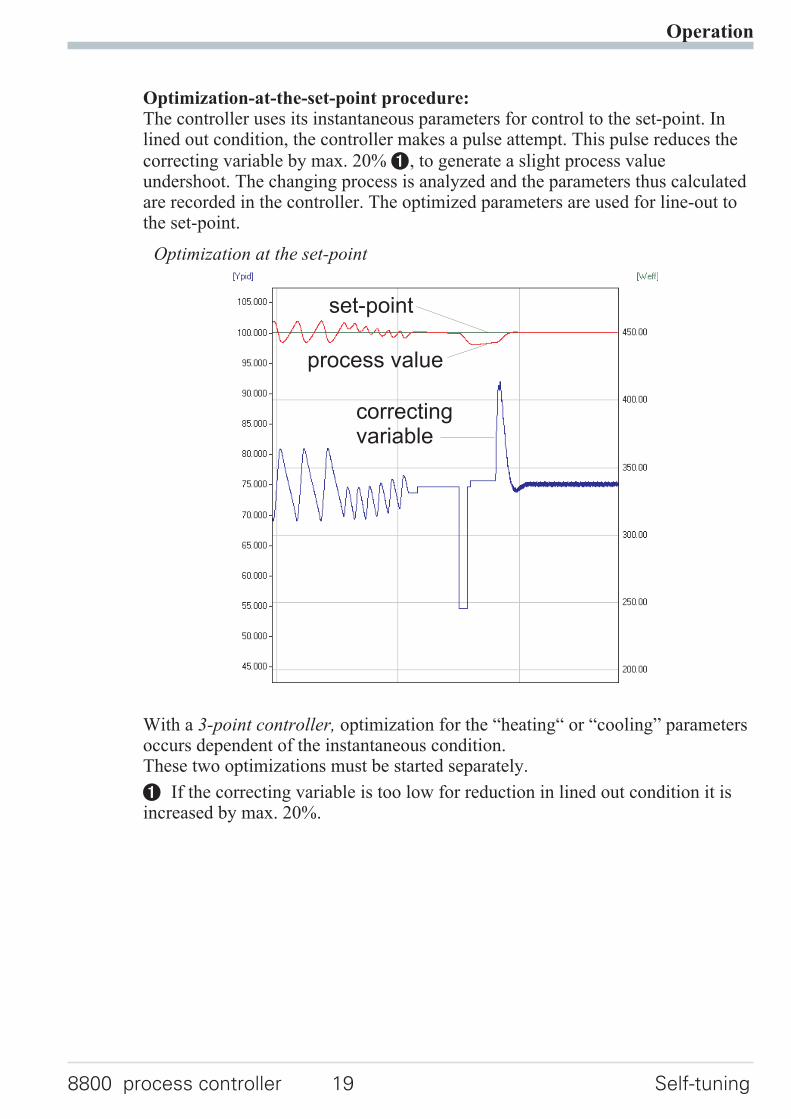
Optimization-at-the-set-point procedure:The controller uses its instantaneous parameters for control to the set-point. Inlined out condition, the controller makes a pulse attempt. This pulse reduces the
correcting variable by max. 20% 1, to generate a slight process valueundershoot. The changing process is analyzed and the parameters thus calculatedare recorded in the controller. The optimized parameters are used for line-out tothe set-point.
With a 3-point controller, optimization for the “heating“ or “cooling” parametersoccurs dependent of the instantaneous condition.These two optimizations must be started separately.
1 If the correcting variable is too low for reduction in lined out condition it isincreased by max. 20%.
Operation
8800 process controller 19 Self-tuning
set-point
process value
correctingvariable
Optimization at the set-point
Optimization at the set-point for 3-point stepping controller
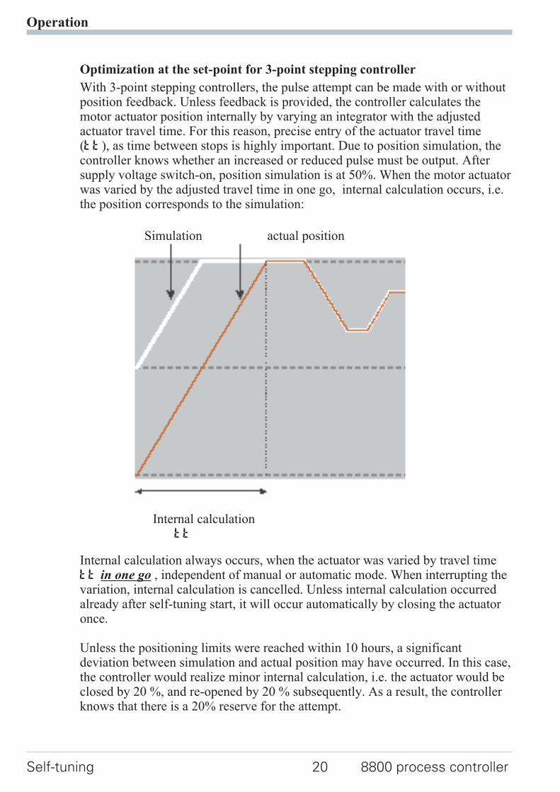
With 3-point stepping controllers, the pulse attempt can be made with or withoutposition feedback. Unless feedback is provided, the controller calculates themotor actuator position internally by varying an integrator with the adjustedactuator travel time. For this reason, precise entry of the actuator travel time(tt), as time between stops is highly important. Due to position simulation, thecontroller knows whether an increased or reduced pulse must be output. Aftersupply voltage switch-on, position simulation is at 50%. When the motor actuatorwas varied by the adjusted travel time in one go, internal calculation occurs, i.e.the position corresponds to the simulation:
Simulation actual position
Internal calculationtt
Internal calculation always occurs, when the actuator was varied by travel timett in one go , independent of manual or automatic mode. When interrupting thevariation, internal calculation is cancelled. Unless internal calculation occurredalready after self-tuning start, it will occur automatically by closing the actuatoronce.
Unless the positioning limits were reached within 10 hours, a significantdeviation between simulation and actual position may have occurred. In this case,the controller would realize minor internal calculation, i.e. the actuator would beclosed by 20 %, and re-opened by 20 % subsequently. As a result, the controllerknows that there is a 20% reserve for the attempt.
Operation
Self-tuning 20 8800 process controller
3.5.4 Self-tuning start
Start condition:w For process evaluation, a stable condition is required. Therefore, the
controller waits until the process has reached a stable condition afterself-tuning start.The rest condition is considered being reached, when the process value
oscillation is smaller than ± 0,5% of (rnG.H - rnG.L).
w For self-tuning start after start-up, a 10% difference from (SP.LO ... SP.Hi)is required.
g Self-tuning start can be blocked via 8800/8840 configurator® (engineering tool)( P.Loc).
Strt = 0 Only manual start by pressing keys Ù and Èsimultaneously or via interface is possible.
Strt = 1 Manual start by press keys Ù and È simultaneouslyvia interface and automatic start after power-on and detection
of process oscillations.
3.5.5 Self-tuning cancellation
By the operator:
Self-tuning can always be cancelled by the operator. For this, press Ù and Èkey simultaneously.With controller switch-over to manual mode after self-tuningstart, self-tuning is cancelled. When self-tuning is cancelled, the controller willcontinue operating using the old parameter values.
By the controller:If the Err LED starts blinking whilst self-tuning is running, successful self-tuningis prevented due to the control conditions. In this case, self-tuning was cancelledby the controller. The controller continues operating with the old parameters inautomatic mode. In manual mode it continues with the old controller outputvalue.
3.5.6 Acknowledgement procedures in case of unsuccessful self-tuning
Operation
8800 process controller 21 Self-tuning
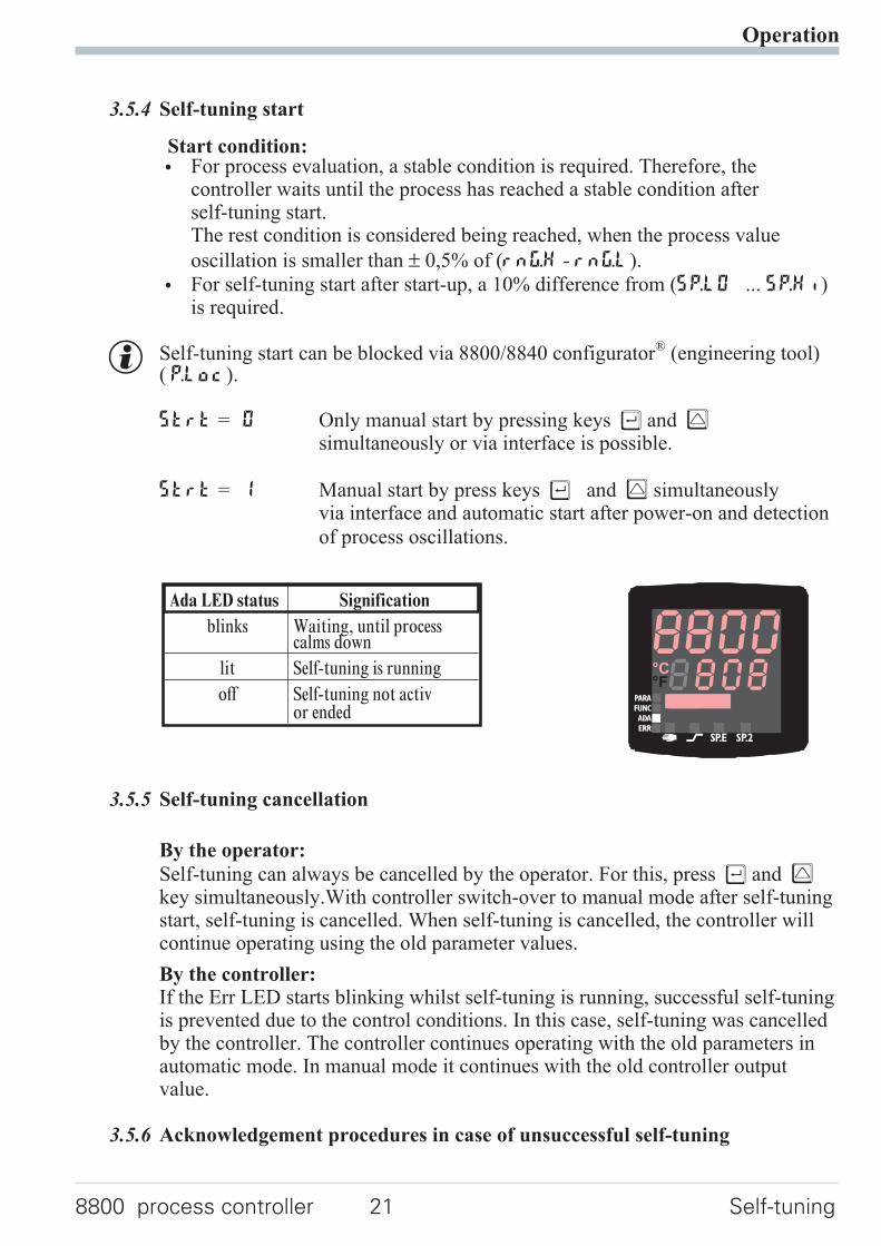
Ada LED status Signification
blinks Waiting, until processcalms down
lit Self-tuning is running
off Self-tuning not activor ended
°C°F
1. Press keys Ù and È simultaneously:The controller continues controlling using the old parameters in automaticmode. The Err LED continues blinking, until the self-tuning error wasacknowledged in the error list.
2. Press key Ò (if configured):The controller goes to manual mode. The Err LED continues blinking,until the self-tuning error was acknowleged in the error list.
3. Press key Ù :Display of error list at extended operating level. After acknowledgementof the error message, the controller continues control in automatic mode usingthe old parameters.
Cancellation causes:
r page 15: "Error status self-tuning heating ( ADA.H) and cooling ( ADA.C)"
Operation
Self-tuning 22 8800 process controller
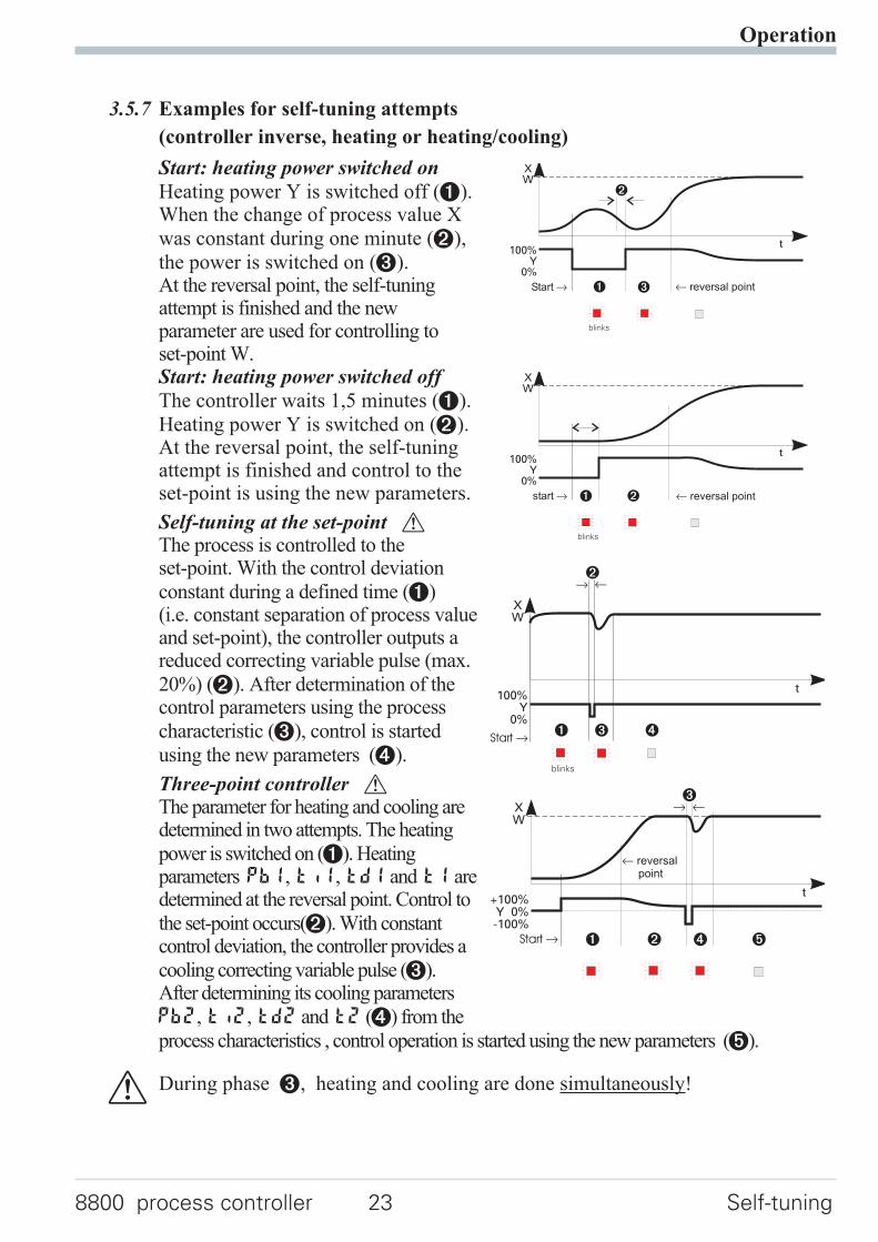
3.5.7 Examples for self-tuning attempts
(controller inverse, heating or heating/cooling)
Start: heating power switched on
Heating power Y is switched off (1).When the change of process value X
was constant during one minute (2),
the power is switched on (3).At the reversal point, the self-tuningattempt is finished and the newparameter are used for controlling toset-point W.Start: heating power switched off
The controller waits 1,5 minutes (1).
Heating power Y is switched on (2).At the reversal point, the self-tuningattempt is finished and control to theset-point is using the new parameters.
Self-tuning at the set-point aThe process is controlled to theset-point. With the control deviation
constant during a defined time (1)(i.e. constant separation of process valueand set-point), the controller outputs areduced correcting variable pulse (max.
20%) (2). After determination of thecontrol parameters using the process
characteristic (3), control is started
using the new parameters (4).
Three-point controller aThe parameter for heating and cooling aredetermined in two attempts. The heating
power is switched on (1). Heatingparameters Pb1, ti1, td1 and t1 aredetermined at the reversal point. Control to
the set-point occurs(2). With constantcontrol deviation, the controller provides a
cooling correcting variable pulse (3).After determining its cooling parameters
Pb2, ti2, td2 and t2 (4) from the
process characteristics , control operation is started using the new parameters (5).
a During phase 3, heating and cooling are done simultaneously!
Operation
8800 process controller 23 Self-tuning
t
2
100%Y
0%
XW
Start r 1 3 t reversal point
blinks
t100%
Y0%
XW
start r 1 2 t reversal point
blinks
t
2
100%Y
0%
XW
1 3
blinks
4
r t
Start r
t+100%Y 0%-100%
XW
t reversalpoint
Start r 1 2
3
4 5
r t
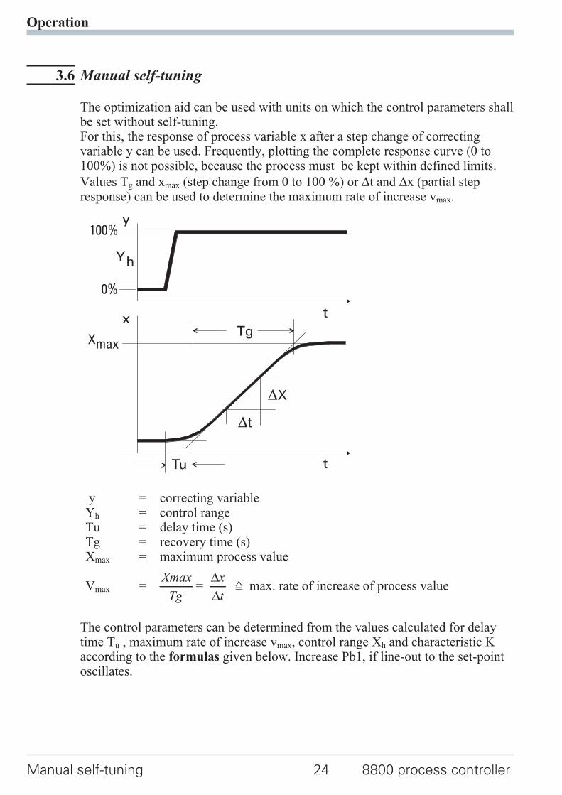
3.6 Manual self-tuning
The optimization aid can be used with units on which the control parameters shallbe set without self-tuning.For this, the response of process variable x after a step change of correctingvariable y can be used. Frequently, plotting the complete response curve (0 to100%) is not possible, because the process must be kept within defined limits.
Values Tg and xmax (step change from 0 to 100 %) or ∆t and ∆x (partial stepresponse) can be used to determine the maximum rate of increase vmax.
y = correcting variableYh = control rangeTu = delay time (s)Tg = recovery time (s)Xmax = maximum process value
Vmax =Xmax
Tg=
∆∆
x
t= max. rate of increase of process value
The control parameters can be determined from the values calculated for delaytime Tu , maximum rate of increase vmax, control range Xh and characteristic Kaccording to the formulas given below. Increase Pb1, if line-out to the set-pointoscillates.
Operation
Manual self-tuning 24 8800 process controller
Tu
Tg
t
x
y100%
0%
t
Yh
Xmax
X
t
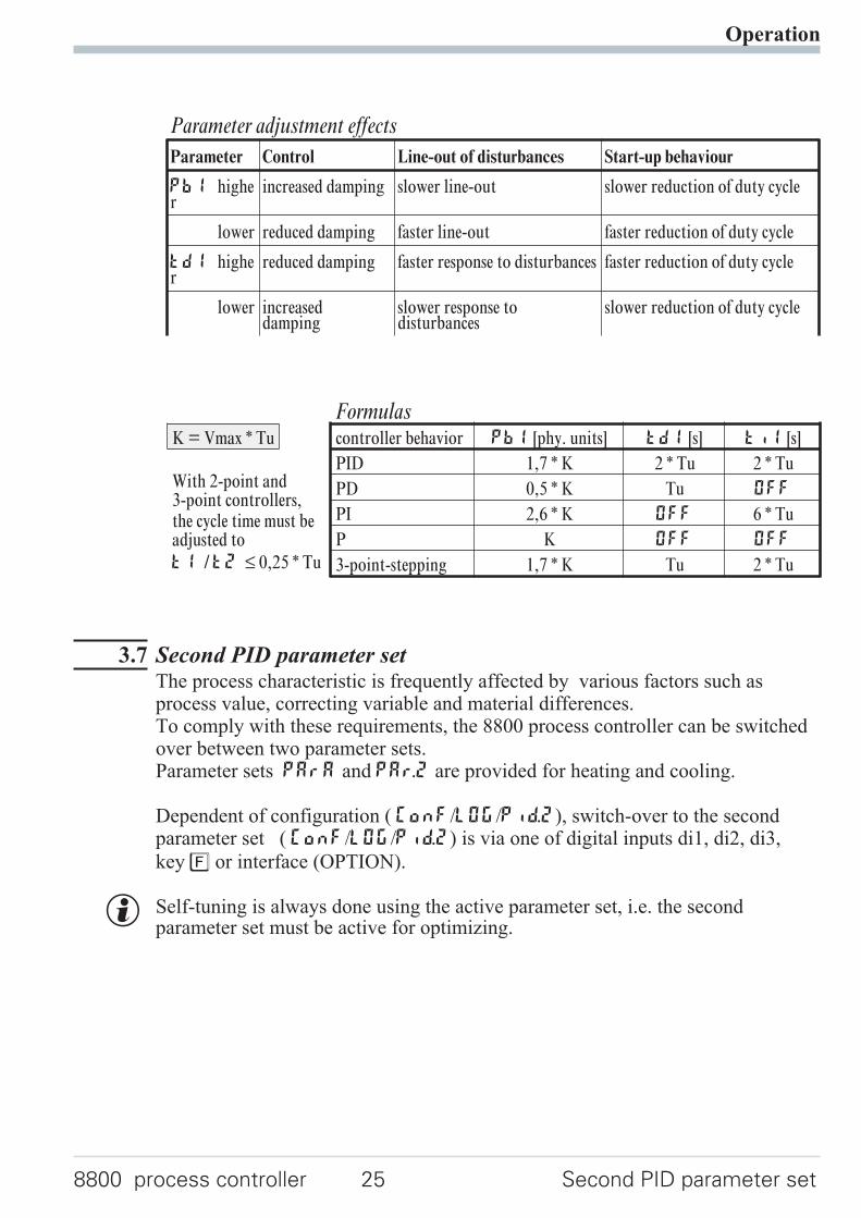
3.7 Second PID parameter setThe process characteristic is frequently affected by various factors such asprocess value, correcting variable and material differences.To comply with these requirements, the 8800 process controller can be switchedover between two parameter sets.Parameter sets PArA and PAr.2 are provided for heating and cooling.
Dependent of configuration ( ConF/LOG/Pid.2), switch-over to the secondparameter set ( ConF/LOG/Pid.2) is via one of digital inputs di1, di2, di3,
key è or interface (OPTION).
g Self-tuning is always done using the active parameter set, i.e. the secondparameter set must be active for optimizing.
Operation
8800 process controller 25 Second PID parameter set
FormulasK = Vmax * Tu controller behavior Pb1 [phy. units] td1 [s] ti1 [s]
With 2-point and3-point controllers,the cycle time must beadjusted to
t1 /t2 ≤ 0,25 * Tu
PID 1,7 * K 2 * Tu 2 * Tu
PD 0,5 * K Tu OFF
PI 2,6 * K OFF 6 * Tu
P K OFF OFF
3-point-stepping 1,7 * K Tu 2 * Tu
Parameter adjustment effects
Parameter Control Line-out of disturbances Start-up behaviour
Pb1 higher
increased damping slower line-out slower reduction of duty cycle
lower reduced damping faster line-out faster reduction of duty cycle
td1 higher
reduced damping faster response to disturbances faster reduction of duty cycle
lower increaseddamping
slower response todisturbances
slower reduction of duty cycle
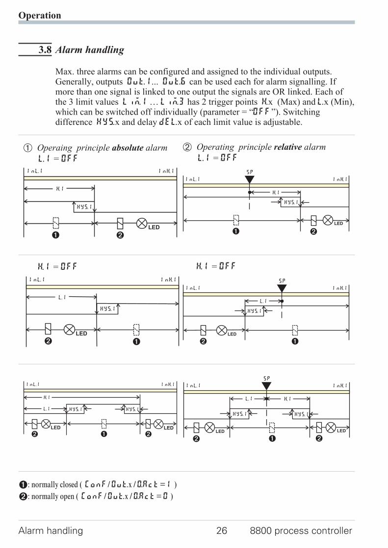
3.8 Alarm handling
Max. three alarms can be configured and assigned to the individual outputs.Generally, outputs OuT.1... OuT.6 can be used each for alarm signalling. Ifmore than one signal is linked to one output the signals are OR linked. Each ofthe 3 limit values Lim.1 … Lim.3 has 2 trigger points H.x (Max) and L.x (Min),which can be switched off individually (parameter = “OFF”). Switchingdifference HYS.x and delay dEl.x of each limit value is adjustable.
1: normally closed ( ConF/Out.x /O.Act=1 )
2: normally open ( ConF/Out.x /O.Act=0 )
Operation
Alarm handling 26 8800 process controller
H.1
LED
HYS.1
InL.1 InH.1
21
Ü Operaing principle absolute alarm
L.1 = OFF
LED
HYS.1
H.1
InL.1 InH.1
SP
21
* Operating principle relative alarm
L.1 = OFF
L.1
LED
HYS.1
InL.1 InH.1
2 1
H.1 = OFF
L.1
LED
HYS.1
InL.1 InH.1
SP
2 1
H.1 = OFF
L.1
LED LED
HYS.1 HYS.1
H.1
InL.1 InH.1
22 1
L.1
LED LED
HYS.1 HYS.1
H.1
InL.1 InH.1
SP
2 21
g The variable to be monitored can be selected seperately for each alarm viaconfigurationThe following variables can be monitored:
w process value
w control deviation xw (process value - set-point)
w control deviation xw + suppression after start-up or set-point changeAfter switching on or set-point changing, the alarm output is suppressed,
until the process value is within the limits for the first time. At the latest afterexpiration of time 10 ti1, the alarm is activated. (ti1 = integral time 1;
parameter r Cntr)
If ti1 is switched off (ti1 = OFF), this is interpreted as Î, i.e. the alarmis not activated, before the process value was within the limits once.
w Measured value INP1
w Measured value INP2
w Measured value INP3
w effective set-point Weff
w correcting variable y (controller output)
w Deviation from SP internal
w Process value - x2
g If measured value monitoring + alarm status storage is chosen ( ConF / Lim /Fnc.x = 2/4), the alarm relay remains switched on until the alarm is resetted inthe error list ( Lim 1..3 = 1).
Operation
8800 process controller 27 Alarm handling
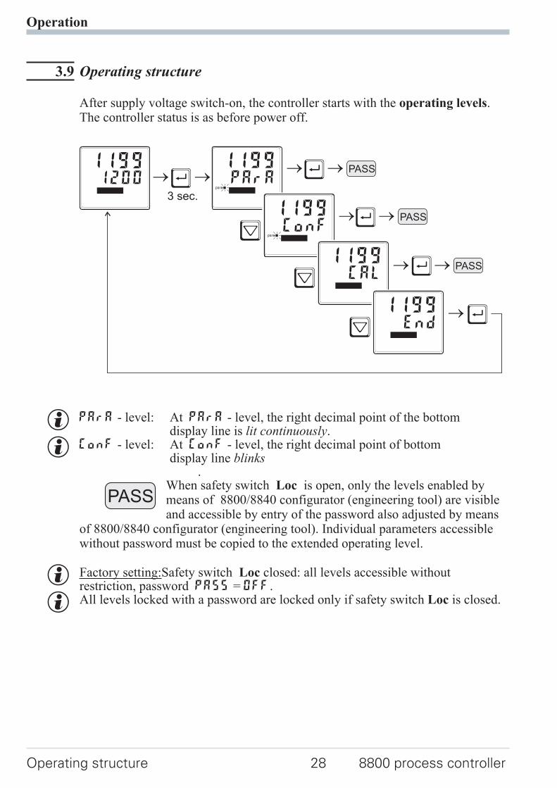
3.9 Operating structure
After supply voltage switch-on, the controller starts with the operating levels.The controller status is as before power off.
g PArA - level: At PArA - level, the right decimal point of the bottomdisplay line is lit continuously.
g ConF - level: At ConF - level, the right decimal point of bottomdisplay line blinks
.When safety switch Loc is open, only the levels enabled bymeans of 8800/8840 configurator (engineering tool) are visibleand accessible by entry of the password also adjusted by means
of 8800/8840 configurator (engineering tool). Individual parameters accessiblewithout password must be copied to the extended operating level.
g Factory setting:Safety switch Loc closed: all levels accessible withoutrestriction, password PASS = OFF.
g All levels locked with a password are locked only if safety switch Loc is closed.
Operation
Operating structure 28 8800 process controller
Ù
Ù
Ù
Ù
Ù
Ì
Ì
Ì
3 sec.
PASS12001199
PArA1199
para
ConF1199
para
CAL1199
End1199
PASS
PASS
PASS
4 Configuration level
4.1 Configuration survey
Adjustment:
w The configuration can be adjusted by means of keys ÈÌ .
w Transition to the next configuration is by pressing key Ù .
w After the last configuration of a group, donE is displayed and followed byautomatic change to the next group
Return to the beginning of a group is by pressing the Ù key for 3 sec.
Configuration level
8800 process controller 29 Configuration survey
ConF Configuration level
ÈÌ
Cntr
Con
trol
and
self
-tun
ing
InP.1
Inpu
t1
InP.2
Inpu
t2
InP.3
Inpu
t3
Lim
Lim
itva
lue
func
tion
s
OUt.1
Out
put
1
OUt.2
Out
put
2
OUt.3
Out
put
3
OUt.4
Out
put
4
Out.5
Out
put
5
Out.6
Out
put
6
LOGI
Dig
ital
inpu
ts
Othr
Dis
play
,ope
rati
on,
inte
rfac
e
SP.Fn I.Fnc I.Fnc I.Fnc Fnc.1 O.Act
See
outp
ut1
O.tYP O.tYP
See
outp
ut1
See
outp
ut1
L_r bAud
C.tYP StYP StYP S.Lin Src.1 Y.1 O.Act O.Act SP.2 Addr
C.Fnc S.Lin Corr S.Typ Fnc.2 Y.2 Y.1 Y.1 SP.E PrtY
C.dif Corr In.F Corr Src.2 Lim.1 Y.2 Y.2 Y.2 dELY
mAn In.F Fnc.3 Lim.2 Lim.1 Lim.1 Y.E dp.Ad
C.Act Src.3 Lim.3 Lim.2 Lim.2 mAn bc.up
FAIL HC.AL dAc.A Lim.3 Lim.3 C.oFF O2
rnG.L LP.AL LP.AL dAc.A dAc.A m.Loc Unit
rnG.H dAc.A HC.AL LP.AL LP.AL Err.r dP
CYCL HC.SC HC.AL HC.AL Pid.2 LEd
tunE P.End HC.SC HC.SC I.Chg dISP
Strt FAi.1 P.End P.End di.Fn C.dEl
FAi.2 FAi.1 FAi.1
FAi.3 FAi.2 FAi.2
FAi.3 FAi.3
OuT.0 OuT.0
Out.1 Out.1
O.Src O.Src
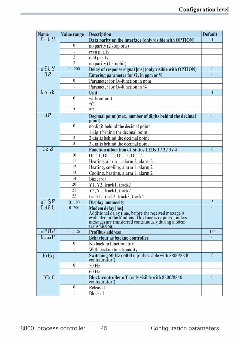
4.2 Configuration parameters
Configuration level
Configuration parameters 30 8800 process controller
Cntr
Name Value range Description DefaultSP.Fn Basic configuration of setpoint processing 0
0 set-point controller can be switched over to external set-point(->LOGI/SP.E)
8 standard controller with external offset (SP.E)C.tYP Calculation of the process value 0
0 standard controller (process value = x1)1 ratio controller (x1/x2)2 difference (x1 - x2)3 Maximum value of x1and x2. It is controlled with the bigger
value. At sensor failure it is controlled with the remainingactual value.
4 Minimum value of x1and x2. It is controlled with the smallervalue. At sensor failure it is controlled with the remainingactual value.
5 Mean value (x1, x2). With sensor error, controlling iscontinued with the remaining process value.
6 Switching between x1 and x2 (->LOGI/I.ChG)7 O2 function with constant sensor temperature8 O2 function with measured sensor temperature
C.Fnc Control behaviour (algorithm) 1
0 on/off controller or signaller with one output1 PID controller (2-point and continuous)2 ∆ / Y / Off, or 2-point controller with partial/full load
switch-over3 2 x PID (3-point and continuous)4 3-point stepping controller5 3-point stepping controller with position feedback Yp6 continuous controller with integrated positioner
C.dif Output action of the PID controller derivative action 0
0 Derivative action acts only on the measured value.1 Derivative action only acts on the control deviation
(set-point is also differentiated)mAn Manual operation permitted 0
0 no1 yes (rLOGI /mAn)
C.Act Method of controller operation 0
0 inverse, e.g. heating1 direct, e.g. cooling
FAIL Behaviour at sensor break 1
0 controller outputs switched off1 y = Y22 y = mean output. The maximum permissible output can be
adjusted with parameterYm.H. To prevent determination ofinadmissible values, mean value formation is only if thecontrol deviation is lower than parameterL.Ym.
Configuration level
8800 process controller 31 Configuration parameters
Name Value range Description DefaultrnG.L -1999...9999 X0 (low limit range of control) 1 -100
rnG.H -1999...9999 X100 (high limit range of control) 1 1200
CYCL Characteristic for 2-point- and 3-point-controllers 0
0 standard1 water cooling linear2 water cooling non-linear3 with constant cycle (see page 51)
tunE Auto-tuning at start-up (see page 16 ) 0
0 At start-up with step attempt, at set-point with impulseattempt
1 At start-up and at set-point with impulse attempt. Setting forfast controlled systems (e.g. hot runner control)
2 Always step attempt at start-upStrt Start of auto-tuning 0
0 Manual start of auto-tuning1 Manual or automatic start of auto-tuning at power on or
when oscillating is detectedAdt0 Optimization of T1, T2 (only visible with 8800/8840
configurator!)0
0 Automatic optimization1 No optimization
1 rnG.L and rnG.H are indicating the range of control on which e.g. theself-tuning is refering
InP.1
Name Value range Description DefaultI.fnc INP1 function selection 7
0 No function (following INP data are skipped)1 Heating current input2 External set-point SP.E (switch-over ->LOGI/SP.E)3 Position feedback Yp4 Second process value x2 (ratio, min, max, mean)5 External positioning value Y.E
(switch-overrLOGI /Y.E)6 No controller input (e.g. limit signalling instead)7 Process value x1
Configuration level
Configuration parameters 32 8800 process controller
Name Value range Description DefaultS.tYP Sensor type selection 1
0 thermocouple type L (-100...900°C) , Fe-CuNi DIN1 thermocouple type J (-100...1200°C) , Fe-CuNi2 thermocouple type K (-100...1350°C), NiCr-Ni3 thermocouple type N (-100...1300°C), Nicrosil-Nisil4 thermocouple type S (0...1760°C), PtRh-Pt10%5 thermocouple type R (0...1760°C), PtRh-Pt13%6 thermocouple type T (-200...400°C), Cu-CuNi7 thermocouple type C (0...2315°C), W5%Re-W26%Re8 thermocouple type D (0...2315°C), W3%Re-W25%Re9 thermocouple type E (-100...1000°C), NiCr-CuNi
10 thermocouple type B (0/100...1820°C), PtRh-Pt6%18 special thermocouple20 Pt100 (-200.0 ... 100,0 °C)21 Pt100 (-200.0 ... 850,0 °C)22 Pt1000 (-200.0 ... 850.0 °C)23 special 0...4500 Ohm (preset to KTY11-6)24 special 0...450 Ohm30 0...20mA / 4...20mA 140 0...10V / 2...10V 141 special -2,5...115 mV 142 special -25...1150 mV 150 potentiometer 0...160 Ohm 151 potentiometer 0...450 Ohm 152 potentiometer 0...1600 Ohm 153 potentiometer 0...4500 Ohm 1
S.Lin Linearization (only atS.tYP= 23 (KTY 11-6), 24(0...450 ), 30 (0..20mA), 40 (0..10V), 41 (0...100mV) and42 (special -25...1150 mV))
0
0 none1 Linearization to specification. Creation of linearization table
with 8800/8840 configurator (engineering tool) possible.The characteristic for KTY 11-6 temperature sensors ispreset.
Corr Measured value correction / scaling 0
0 Without scaling1 Offset correction (at CAL level)2 2-point correction (at CAL level)3 Scaling (at PArA level)
In.f -1999...9999 Alternative value for error at INP1 OFF
fAI1 Forcing INP1 (only visible with 8800/8840 configurator!) 0
0 No forcing1 Forcing via serial interface
1 with current and voltage input signals, scaling is required (see chapter 5.3)
Configuration level
8800 process controller 33 Configuration parameters
InP.2
Name Value range Description DefaultI.Fnc Function selection of INP2 1
0 no function (subsequent input data are skipped)1 heating current input2 External set-point SP.E (switch-over ->LOGI/SP.E)3 Position feedback Yp4 Second process value x2 (ratio, min, max, mean)5 External positioning value Y.E
(switch-overrLOGI /Y.E)6 no controller input (e.g. transmitter input instead)7 Process value x1
S.tYP Sensor type selection 30
30 0...20mA / 4...20mA 131 0...50mA AC 150 Potentiometer ( 0...160 Ohm) 151 Potentiometer ( 0...450 Ohm) 152 Potentiometer ( 0...1600 Ohm) 153 Potentiometer ( 0...4500 Ohm) 1
Corr Measured value correction / scaling 00 Without scaling1 Offset correction (at CAL level)2 2-point correction (at CALlevel)3 Scaling (at PArA level)
In.F -1999...9999 Alternative value for error at INP2 OFF
fAI2 Forcing INP2 (only visible with 8800/8840 configurator!) 0
0 No forcing1 Forcing via serial interface
1 with current and voltage input signals, scaling is required (see chapter 5.3)
InP.3
Name Value range Description DefaultI.Fnc Function selection of INP3 1
0 no function (subsequent input data are skipped)1 heating current input2 External set-point SP.E (switch-over ->LOGI/SP.E)3 Yp input4 Second process value X25 External positioning value Y.E
(switch-overrLOGI /Y.E)6 no controller input (e.g. transmitter input instead)7 Process value x1
Configuration level
Configuration parameters 34 8800 process controller
Name Value range Description DefaultS.tYP Sensor type selection 30
0 thermocouple type L (-100...900°C) , Fe-CuNi DIN1 thermocouple type J (-100...1200°C) , Fe-CuNi2 thermocouple type K (-100...1350°C), NiCr-Ni3 thermocouple type N (-100...1300°C), Nicrosil-Nisil4 thermocouple type S (0...1760°C), PtRh-Pt10%5 thermocouple type R (0...1760°C), PtRh-Pt13%6 thermocouple type T (-200...400°C), Cu-CuNi7 thermocouple type C (0...2315°C), W5%Re-W26%Re8 thermocouple type D (0...2315°C), W3%Re-W25%Re9 thermocouple type E (-100...1000°C), NiCr-CuNi
10 thermocouple type B (0/100...1820°C), PtRh-Pt6%18 special thermocouple20 Pt100 (-200.0 ... 100,0 °C)21 Pt100 (-200.0 ... 850,0 °C)22 Pt1000 (-200.0 ... 850.0 °C)23 special 0...4500 Ohm (preset to KTY11-6)24 special 0...450 Ohm30 0...20mA / 4...20mA 141 special -2,5...115 mV 142 special -25...115 0mV 150 potentiometer 0...160 Ohm 151 potentiometer 0...450 Ohm 152 potentiometer 0...1600 Ohm 153 potentiometer 0...4500 Ohm 1
S.Lin Linearization(only atS.tYP= 23,24,30,41 and 42 adjustable)
0
0 none1 Linearization to specification. Creation of linearization table
with 8800/8840 configurator (engineering tool) possible.The characteristic for KTY 11-6 temperature sensors ispreset.
Corr Measured value correction / scaling(only atS.tYP= 23,24,30,41 and 42 adjustable)
0
0 Without scaling1 Offset correction (at CAL level)2 2-point correction (at CAL level)3 Scaling (at PArA level)4 Automatic calibration (DAC)
In.F -1999...9999 Alternative value for error at INP3 OFF
fAI3 Forcing INP3 (only visible with 8800/8840 configurator!) 0
0 No forcing1 Forcing via serial interface
1 with current and voltage input signals, scaling is required (see chapter 5.3)
Configuration level
8800 process controller 35 Configuration parameters
Lim
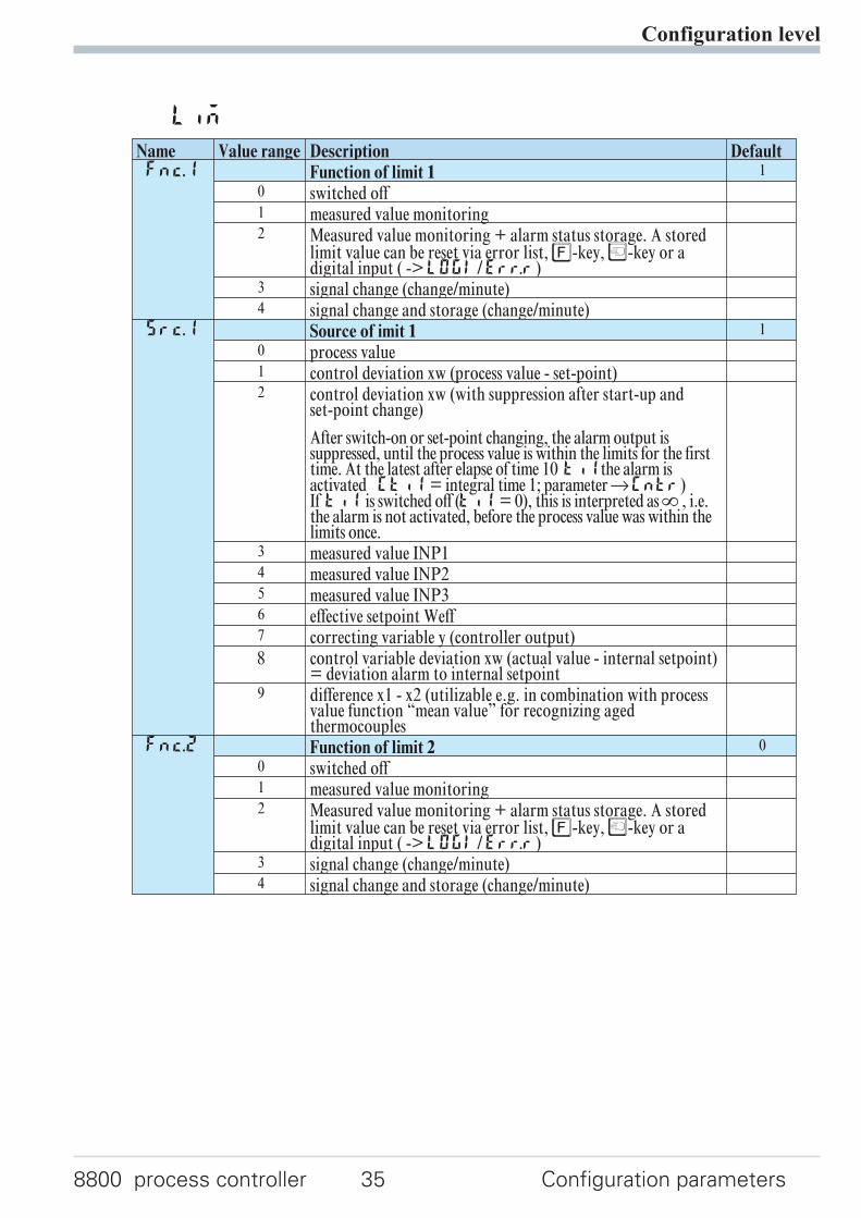
Name Value range Description DefaultFnc.1 Function of limit 1 1
0 switched off1 measured value monitoring2 Measured value monitoring + alarm status storage. A stored
limit value can be reset via error list,è-key,Ò-key or adigital input ( ->LOGI/Err.r)
3 signal change (change/minute)4 signal change and storage (change/minute)
Src.1 Source of imit 1 1
0 process value1 control deviation xw (process value - set-point)2 control deviation xw (with suppression after start-up and
set-point change)
After switch-on or set-point changing, the alarm output issuppressed, until the process value is within the limits for the firsttime. At the latest after elapse of time 10 ti1the alarm isactivated (ti1= integral time 1; parameterrCntr)If ti1 is switched off (ti1= 0), this is interpreted asÎ , i.e.the alarm is not activated, before the process value was within thelimits once.
3 measured value INP14 measured value INP25 measured value INP36 effective setpoint Weff7 correcting variable y (controller output)8 control variable deviation xw (actual value - internal setpoint)
= deviation alarm to internal setpoint9 difference x1 - x2 (utilizable e.g. in combination with process
value function “mean value” for recognizing agedthermocouples
Fnc.2 Function of limit 2 0
0 switched off1 measured value monitoring2 Measured value monitoring + alarm status storage. A stored
limit value can be reset via error list,è-key,Ò-key or adigital input ( ->LOGI/Err.r)
3 signal change (change/minute)4 signal change and storage (change/minute)
Configuration level
Configuration parameters 36 8800 process controller
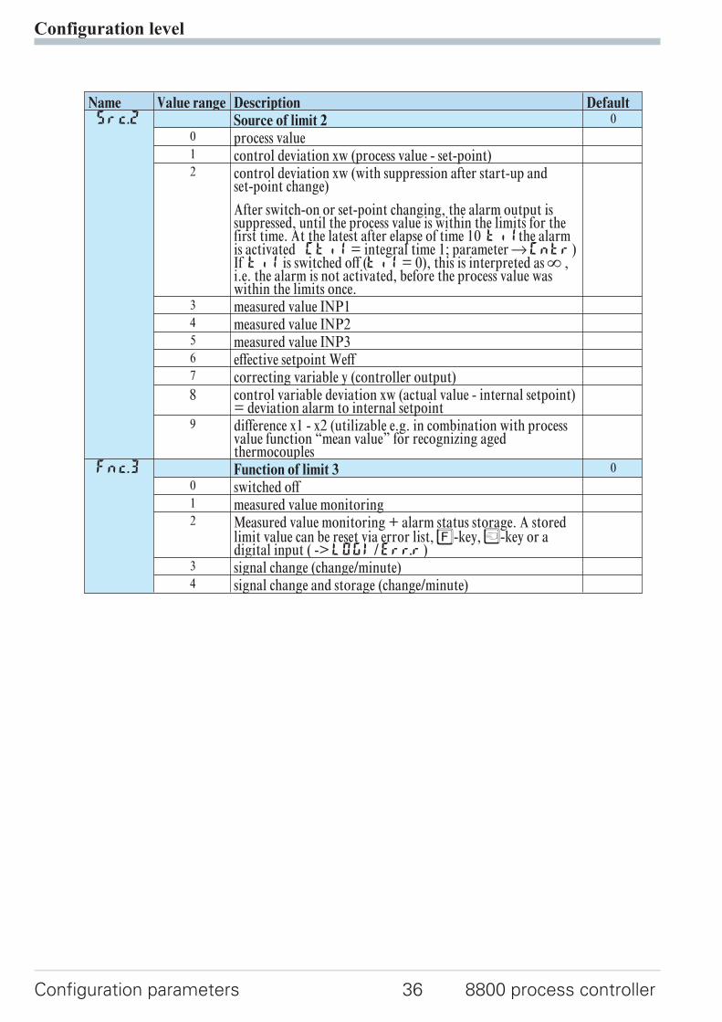
Name Value range Description DefaultSrc.2 Source of limit 2 0
0 process value1 control deviation xw (process value - set-point)2 control deviation xw (with suppression after start-up and
set-point change)
After switch-on or set-point changing, the alarm output issuppressed, until the process value is within the limits for thefirst time. At the latest after elapse of time 10 ti1the alarmis activated (ti1= integral time 1; parameterrCntr)If ti1 is switched off (ti1= 0), this is interpreted asÎ ,i.e. the alarm is not activated, before the process value waswithin the limits once.
3 measured value INP14 measured value INP25 measured value INP36 effective setpoint Weff7 correcting variable y (controller output)8 control variable deviation xw (actual value - internal setpoint)
= deviation alarm to internal setpoint9 difference x1 - x2 (utilizable e.g. in combination with process
value function “mean value” for recognizing agedthermocouples
Fnc.3 Function of limit 3 0
0 switched off1 measured value monitoring2 Measured value monitoring + alarm status storage. A stored
limit value can be reset via error list,è-key,Ò-key or adigital input ( ->LOGI/Err.r)
3 signal change (change/minute)4 signal change and storage (change/minute)
Configuration level
8800 process controller 37 Configuration parameters
Name Value range Description DefaultSrc.3 Source of limit 3 0
0 process value1 control deviation xw (process value - set-point)2 control deviation xw (with suppression after start-up and
set-point change)
After switch-on or set-point changing, the alarm output issuppressed, until the process value is within the limits for thefirst time. At the latest after elapse of time 10 ti1 the alarmis activated (ti1= integral time 1; parameterrCntr)If ti1 is switched off (ti1= 0), this is interpreted asÎ ,i.e. the alarm is not activated, before the process value waswithin the limits once.
3 measured value INP14 measured value INP25 measured value INP36 effective setpoint Weff7 correcting variable y (controller output)8 control variable deviation xw (actual value - internal setpoint)
= deviation alarm to internal setpoint9 difference x1 - x2 (utilizable e.g. in combination with process
value function “mean value” for recognizing agedthermocouples
HC.AL Alarm heat current function (INP2) 0
0 switched off1 Overload short circuit monitoring2 Break and short circuit monitoring
LP.AL Monitoring of control loop interruption for heating 0
0 switched off / inactive1 active.
If ti1=0 LOOP alarm is inactive!dAc.A DAC alarm function 0
0 DAC alarm switched off / inactive1 DAC alarm active
Hour OFF...999999 Operating hours (only visible with 8800/8840 configurator!) OFF
Swit OFF...999999 Output switching cycles (only visible with 8800/8840configurator!)
OFF
Out.1
Name Value range Description DefaultO.Act Method of operation of output OUT1 0
0 direct / normally open1 inverse / normally closed
Y.1 Controller output Y1 1
0 not active1 active
Configuration level
Configuration parameters 38 8800 process controller
Name Value range Description DefaultY.2 Controller output Y2 0
0 not active1 active
Lim.1 Limit 1 signal 0
0 not active1 active
Lim.2 Limit 2 signal 0
0 not active1 active
Lim.3 Limit 3 signal 0
0 not active1 active
dAc.A Valve monitoring (DAC) 0
0 not active1 active
LP.AL Interruption alarm signal (LOOP) 0
0 not active1 active
HC.AL Heat current alarm signal 0
0 not active1 active
HC.SC Solid state relay (SSR) short circuit signal 0
0 not active1 active
FAi.1 INP1 error signal 0
0 not active1 active
FAi.2 INP2 error signal 0
0 not active1 active
FAi.3 INP3 error signal 0
0 not active1 aktiv
fOut Forcing OUT1 (only visible with 8800/8840 configurator!) 0
0 No forcing1 Forcing via serial interface
Out.2
Configuration parameters Out.2 = Out.1 except for: Default Y.1 = 0 Y.2 = 1
Configuration level
8800 process controller 39 Configuration parameters
Out.3
Name Value range Description DefaultO.tYP Signal type selection OUT3 0
0 relay / logic (only visible with current/logic voltage)1 0 ... 20 mA continuous (only visible with
current/logic/voltage)2 4 ... 20 mA continuous (only visible with
current/logic/voltage)3 0...10 V continuous (only visible with current/logic/voltage)4 2...10 V continuous (only visible with current/logic/voltage)5 transmitter supply (only visible without OPTION)
O.Act Method of operation of output OUT3 (only visible whenO.TYP=0)
1
0 direct / normally open1 inverse / normally closed
Y.1 Controller output Y1 (only visible when O.TYP=0) 0
0 not active1 active
Y.2 Controller output Y2 (only visible when O.TYP=0) 0
0 not active1 active
Lim.1 Limit 1 signal (only visible when O.TYP=0) 1
0 not active1 active
Lim.2 Limit 2 signal (only visible when O.TYP=0) 0
0 not active1 active
Lim.3 Limit 3 signal (only visible when O.TYP=0) 0
0 not active1 active
dAc.A Valve monitoring (DAC) (only visible when O.TYP=0) 0
0 not active1 active
LP.AL Interruption alarm signal (LOOP) (only visible whenO.TYP=0)
0
0 not active1 active
HC.AL Heating current alarm signal (only visible when O.TYP=0) 0
0 not active1 active
HC.SC Solid state relay (SSR) short circuit signal (only visiblewhen O.TYP=0)
0
0 not active1 active
Configuration level
Configuration parameters 40 8800 process controller
Name Value range Description DefaultFAi.1 INP1 error (only visible when O.TYP=0) 1
0 not active1 active
FAi.2 INP2 error (only visible when O.TYP=0) 0
0 not active1 active
FAi.3 INP3 error (only visible when O.TYP=0) 0
0 not active1 aktiv
Out.0 -1999...9999 Scaling of the analog output for 0% (0/4mA or 0/2V, onlyvisible when O.TYP=1..5)
0
Out.1 -1999...9999 Scaling of the analog output for 100% (20mA or 10V, onlyvisible when O.TYP=1..5)
100
O.Src Signal source of the analog output OUT3 (only visible whenO.TYP=1..5)
1
0 not used1 controller output y1 (continuous)2 controller output y2 (continuous)3 process value4 effective set-point Weff5 control deviation xw (process value - set-point)6 measured value position feedback Yp7 measured value INP18 measured value INP29 measured value INP3
fOut Forcing OUT3 (only visible with 8800/8840 configurator!) 0
0 No forcing1 Forcing via serial interface
Out.4
Name Value range Description DefaultO.tYP Signal type selection OUT4 0
0 relay / logic (only visible with current/logic voltage)1 0 ... 20 mA continuous (only visible with
current/logic/voltage)2 4 ... 20 mA continuous (only visible with
current/logic/voltage)3 0...10 V continuous (only visible with current/logic/voltage)4 2...10 V continuous (only visible with current/logic/voltage)5 transmitter supply (only visible without OPTION)
O.Act Method of operation of output OUT4 (only visible whenO.TYP=0)
0
0 direct / normally open1 inverse / normally closed
Configuration level
8800 process controller 41 Configuration parameters
Name Value range Description DefaultY.1 Controller output Y1 (only visible when O.TYP=0) 0
0 not active1 active
Y.2 Controller output Y2 (only visible when O.TYP=0) 0
0 not active1 active
Lim.1 Limit 1 signal (only visible when O.TYP=0) 0
0 not active1 active
Lim.2 Limit 2 signal (only visible when O.TYP=0) 0
0 not active1 active
Lim.3 Limit 3 signal (only visible when O.TYP=0) 0
0 not active1 active
dAc.A Valve monitoring (DAC) (only visible when O.TYP=0) 0
0 not active1 active
LP.AL Interruption alarm signal (LOOP) (only visible whenO.TYP=0)
0
0 not active1 active
HC.AL Heat current alarm signal (only visible when O.TYP=0) 0
0 not active1 active
HC.SC Solid state relay (SSR) short circuit signal (only visiblewhen O.TYP=0)
0
0 not active1 active
FAi.1 INP1 error (only visible when O.TYP=0) 0
0 not active1 active
FAi.2 INP2 error (only visible when O.TYP=0) 0
0 not active1 active
FAi.3 INP3 error (only visible when O.TYP=0) 0
0 not active1 aktiv
Out.0 -1999...9999 Scaling of the analog output for 0% (0/4mA or 0/2V, onlyvisible when O.TYP=1..5)
0
Out.1 -1999...9999 Scaling of the analog output for 100% (20mA or 10V, onlyvisible when O.TYP=1..5)
100
Configuration level
Configuration parameters 42 8800 process controller
Name Value range Description DefaultO.Src Signal source of the analog output OUT4 (only visible when
O.TYP=1..5)0
0 not used1 controller output y1 (continuous)2 controller output y2 (continuous)3 process value4 effective set-point Weff5 control deviation xw (process value - set-point)6 measured value position feedback Yp
fOut Forcing OUT1 (only visible with 8800/8840 configurator!) 0
0 No forcing1 Forcing via serial interface
Out.5
Configuration parameters Out.2 = Out.1 except for: Default Y.1 = 0 Y.2 = 0
Out.6
Configuration parameters Out.2 = Out.1 except for: Default Y.1 = 0 Y.2 = 0
g Method of operation and usage of output Out.1 to Out.6:Is more than one signal chosen active as source, those signals are
OR-linked.
LOGI
Name Value range Description DefaultL_r Local / Remote switching (Remote: adjusting of all values
by front keys is blocked)0
0 no function (switch-over via interface is possible)1 always active2 DI1 switches3 DI2 switches (only visible with OPTION)4 DI3 switches (only visible with OPTION)5 è - key switches
SP.2 Switching to second setpointSP.2 0
0 no function (switch-over via interface is possible)2 DI1 switches3 DI2 switches (only visible with OPTION)4 DI3 switches (only visible with OPTION)5 è - key switches
Configuration level
8800 process controller 43 Configuration parameters
Name Value range Description DefaultSP.E Switching to external setpointSP.E 0
0 no function (switch-over via interface is possible)1 always active2 DI1 switches3 DI2 switches (only visible with OPTION)4 DI3 switches (only visible with OPTION)5 è - key switches
Y2 Y/Y2 switching 0
0 no function (switch-over via interface is possible)2 DI1 switches3 DI2 switches (only visible with OPTION)4 DI3 switches (only visible with OPTION)5 è - key switches6 Ò - key switches
Y.E Switching to fixed control outputY.E 0
0 no function (switch-over via interface is possible)1 always activated (manual station)2 DI1 switches3 DI2 switches (only visible with OPTION)4 DI3 switches (only visible with OPTION)5 è - key switches6 Ò - key switches
mAn Automatic/manual switching 0
0 no function (switch-over via interface is possible)1 always activated (manual station)2 DI1 switches3 DI2 switches (only visible with OPTION)4 DI3 switches (only visible with OPTION)5 è - key switches6 Ò - key switches
C.oFF Switching off the controller 0
0 no function (switch-over via interface is possible)2 DI1 switches3 DI2 switches (only visible with OPTION)4 DI3 switches (only visible with OPTION)5 è - key switches6 Ò - key switches
m.Loc Blockage of hand function 0
0 no function (switch-over via interface is possible)2 DI1 switches3 DI2 switches (only visible with OPTION)4 DI3 switches (only visible with OPTION)5 è - key switches
Configuration level
Configuration parameters 44 8800 process controller
Name Value range Description DefaultErr.r Reset of all error list entries 0
0 no function (switch-over via interface is possible)2 DI1 switches3 DI2 switches (only visible with OPTION)4 DI3 switches (only visible with OPTION)5 è - key switches6 Ò - key switches
Pid.2 Switching of parameter set (Pb, ti, td) 0
0 no function (switch-over via interface is possible)2 DI1 switches3 DI2 switches (only visible with OPTION)4 DI3 switches (only visible with OPTION)5 è - key switches
I.Chg Switching of the actual process value between Inp1 and X2 0
0 no function (switch-over via interface is possible)2 DI1 switches3 DI2 switches (only visible with OPTION)4 DI3 switches (only visible with OPTION)5 è - key switches
di.Fn Function of digital inputs (valid for all inputs) 0
0 direct1 inverse2 toggle key function
fDI1 Forcing di1 (only visible with 8800/8840 configurator!) 0
0 No forcing1 Forcing via serial interface
fDI2 Forcing di2 (only visible with 8800/8840 configurator!) 0
0 No forcing1 Forcing via serial interface
fDI3 Forcing di3 (only visible with 8800/8840 configurator!) 0
0 No forcing1 Forcing via serial interface
othr
Name Value range Description DefaultbAud Baudrate of the interface (only visible with OPTION) 2
0 2400 Baud1 4800 Baud2 9600 Baud3 19200 Baud
Addr 1...247 Address on the interace (only visible with OPTION) 1
Configuration level
8800 process controller 45 Configuration parameters
Name Value range Description DefaultPrtY Data parity on the interface (only visible with OPTION) 1
0 no parity (2 stop bits)1 even parity2 odd parity3 no parity (1 stopbit)
dELY 0...200 Delay of response signal [ms] (only visible with OPTION) 0
O2 Entering parameter for O2 in ppm or % 0
0 Parameter for O2-function in ppm1 Parameter for O2-function in %
Unit Unit 1
0 without unit1 °C2 °F
dP Decimal point (max. number of digits behind the decimalpoint)
0
0 no digit behind the decimal point1 1 digit behind the decimal point2 2 digits behind the decimal point3 3 digits behind the decimal point
LED Function allocation of status LEDs 1 / 2 / 3 / 4 0
10 OUT1, OUT2, OUT3, OUT411 Heating, alarm 1, alarm 2, alarm 312 Heating, cooling, alarm 1, alarm 213 Cooling, heating, alarm 1, alarm 214 Bus error20 Y1, Y2, track1, track221 Y2, Y1, track1, track222 track1, track2, track3, track4
dISP 0...10 Display luminosity 5
C.dEl 0..200 Modem delay [ms]Additional delay time, before the received message isevaluated in the Modbus. This time is required, unlessmessages are transferred continuously during modemtransmission.
0
dP.AD 0...126 Profibus address 126
bc.up Behaviour as backup controller 0
0 No backup functionality1 With backup functionality
FrEq Switching 50 Hz / 60 Hz (only visible with 8800/8840configurator!)
0
0 50 Hz1 60 Hz
ICof Block controller off (only visible with 8800/8840configurator!)
0
0 Released1 Blocked
Configuration level
Configuration parameters 46 8800 process controller
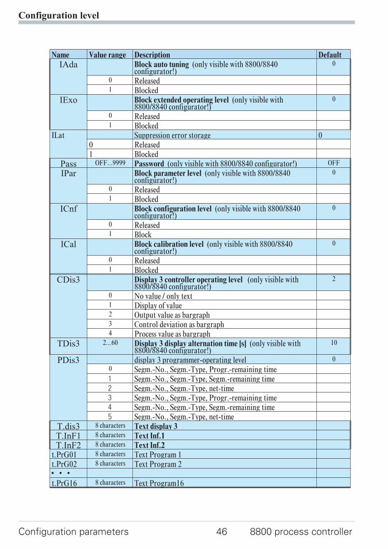
Name Value range Description Default
IAda Block auto tuning (only visible with 8800/8840configurator!)
0
0 Released1 Blocked
IExo Block extended operating level (only visible with8800/8840 configurator!)
0
0 Released1 Blocked
ILat Suppression error storage 00 Released1 Blocked
Pass OFF...9999 Password (only visible with 8800/8840 configurator!) OFF
IPar Block parameter level (only visible with 8800/8840configurator!)
0
0 Released1 Blocked
ICnf Block configuration level (only visible with 8800/8840configurator!)
0
0 Released1 Block
ICal Block calibration level (only visible with 8800/8840configurator!)
0
0 Released1 Blocked
CDis3 Display 3 controller operating level (only visible with8800/8840 configurator!)
2
0 No value / only text1 Display of value2 Output value as bargraph3 Control deviation as bargraph4 Process value as bargraph
TDis3 2...60 Display 3 display alternation time [s] (only visible with8800/8840 configurator!)
10
PDis3 display 3 programmer-operating level 0
0 Segm.-No., Segm.-Type, Progr.-remaining time1 Segm.-No., Segm.-Type, Segm.-remaining time2 Segm.-No., Segm.-Type, net-time3 Segm.-No., Segm.-Type, Progr.-remaining time4 Segm.-No., Segm.-Type, Segm.-remaining time5 Segm.-No., Segm.-Type, net-time
T.dis3 8 characters Text display 3
T.InF1 8 characters Text Inf.1
T.InF2 8 characters Text Inf.2t.PrG01 8 characters Text Program 1t.PrG02 8 characters Text Program 2w w wt.PrG16 8 characters Text Program16
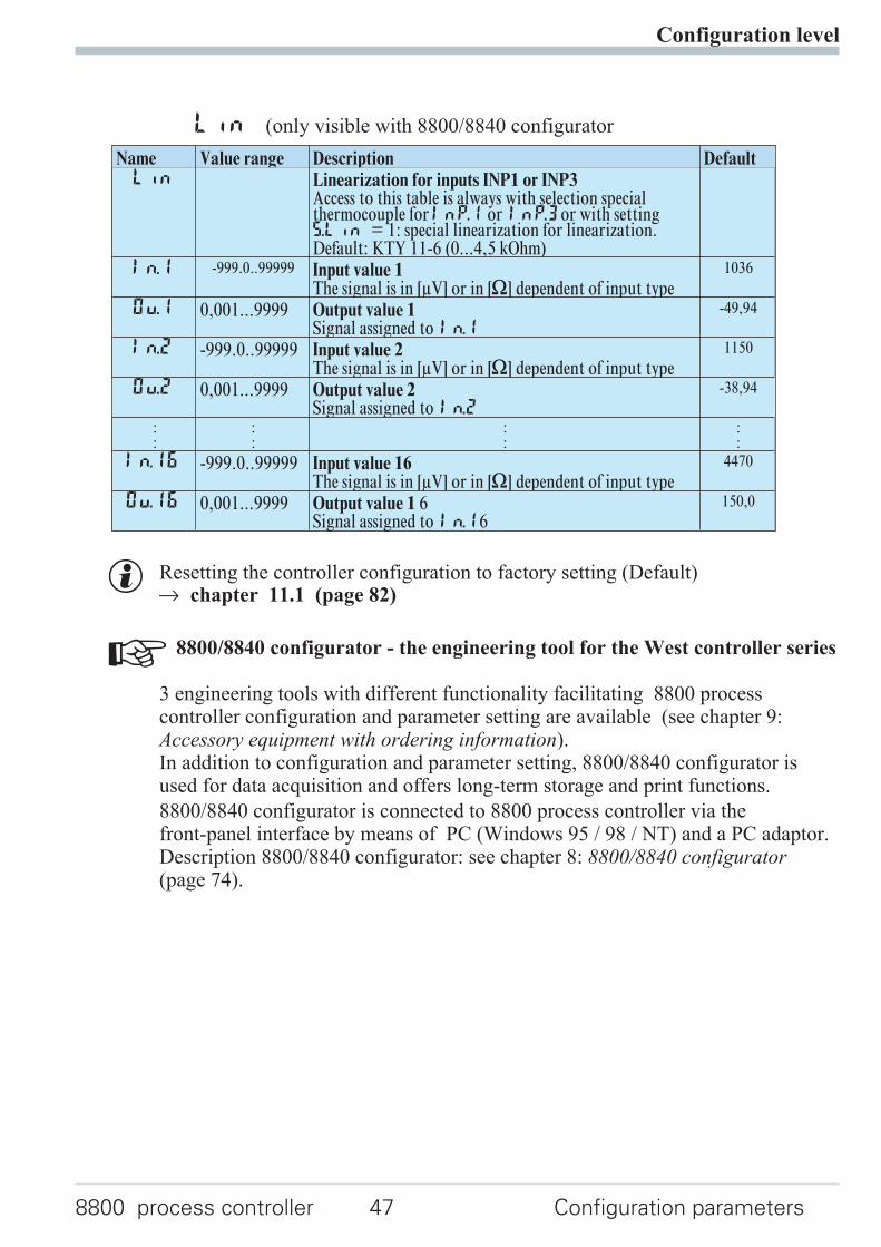
g Resetting the controller configuration to factory setting (Default)r chapter 11.1 (page 82)
+ 8800/8840 configurator - the engineering tool for the West controller series
3 engineering tools with different functionality facilitating 8800 processcontroller configuration and parameter setting are available (see chapter 9:Accessory equipment with ordering information).In addition to configuration and parameter setting, 8800/8840 configurator isused for data acquisition and offers long-term storage and print functions.
8800/8840 configurator is connected to 8800 process controller via thefront-panel interface by means of PC (Windows 95 / 98 / NT) and a PC adaptor.Description 8800/8840 configurator: see chapter 8: 8800/8840 configurator(page 74).
Configuration level
8800 process controller 47 Configuration parameters
Lin (only visible with 8800/8840 configurator
Name Value range Description DefaultLin Linearization for inputs INP1 or INP3
Access to this table is always with selection specialthermocouple forInP.1 or InP.3or with settingS.Lin = 1: special linearization for linearization.Default: KTY 11-6 (0...4,5 kOhm)
In.1 -999.0..99999 Input value 1The signal is in [µV] or in [[] dependent of input type
1036
Ou.1 0,001...9999 Output value 1Signal assigned to In.1
-49,94
In.2 -999.0..99999 Input value 2The signal is in [µV] or in [[] dependent of input type
1150
Ou.2 0,001...9999 Output value 2Signal assigned to In.2
-38,94
::
::
::
::
In.16 -999.0..99999 Input value 16The signal is in [µV] or in [[] dependent of input type
4470
Ou.16 0,001...9999 Output value 1 6Signal assigned to In.16
150,0
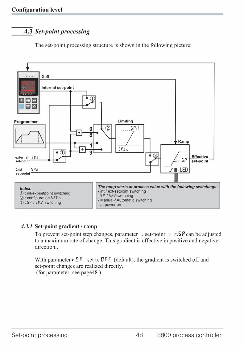
4.3 Set-point processing
The set-point processing structure is shown in the following picture:
4.3.1 Set-point gradient / ramp
To prevent set-point step changes, parameter r set-point r r.SPcan be adjustedto a maximum rate of change. This gradient is effective in positive and negativedirection..
With parameter r.SP set to OFF (default), the gradient is switched off andset-point changes are realized directly.(for parameter: see page48 )
Configuration level
Set-point processing 48 8800 process controller
0
1
Ü
Xeff
SP.2
SP.E
Internal set-point
Programmer
*
Ö
SP.Hi
SP.Lo
r.SP
- LED
externalset-point
Limiting
Ramp
2ndset-point
Effectiveset-point
Ü
+
+
8
9
The ramp starts at process value with the following switchings:- int / ext-setpoint switching- / switching- Manual-/ Automatic switching- at power on
SP SP.2
Index:Ü*Ö
: int/ext-setpoint switching: configuration: / switching
SP.Fn
SP SP.2
WEST 8800
°C°F
Process Controller
4.4 Switching behaviuorWith 8800 process controller, configuration parameter CYCL (ConF/ Cntr/CYCL) can be used for matching the cycle time of 2-point and 3-pointcontrollers. This can be done using the following 4 methods.
4.4.1 Standard ( CyCl= 0 )
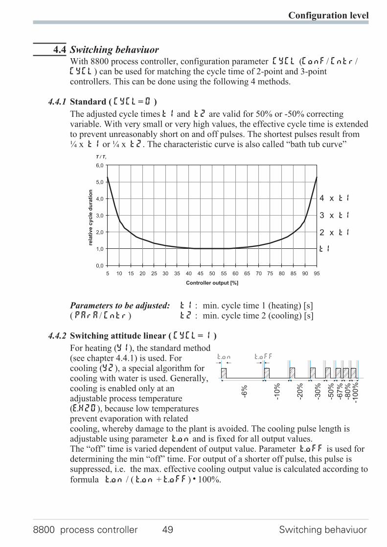
The adjusted cycle times t1 and t2 are valid for 50% or -50% correctingvariable. With very small or very high values, the effective cycle time is extendedto prevent unreasonably short on and off pulses. The shortest pulses result from¼ x t1 or ¼ x t2. The characteristic curve is also called “bath tub curve”
Parameters to be adjusted: t1 : min. cycle time 1 (heating) [s]( PArA/ Cntr) t2 : min. cycle time 2 (cooling) [s]
4.4.2 Switching attitude linear ( CyCl= 1 )
For heating (Y1), the standard method(see chapter 4.4.1) is used. Forcooling (Y2), a special algorithm forcooling with water is used. Generally,cooling is enabled only at anadjustable process temperature(E.H2O), because low temperaturesprevent evaporation with relatedcooling, whereby damage to the plant is avoided. The cooling pulse length isadjustable using parameter t.on and is fixed for all output values.The “off” time is varied dependent of output value. Parameter t.off is used fordetermining the min “off” time. For output of a shorter off pulse, this pulse issuppressed, i.e. the max. effective cooling output value is calculated according to
formula t.on / ( t.on + t.off) w 100%.
Configuration level
8800 process controller 49 Switching behaviuor
0,0
1,0
2,0
3,0
4,0
5,0
6,0
5 10 15 20 25 30 35 40 45 50 55 60 65 70 75 80 85 90 95
Controller output [%]
rela
tiv
ec
yc
led
ura
tio
n
T / T1
t1
2 x t1
3 x t1
4 x t1
-50
%
-67
%-8
0%
-10
0%
-30
%
-20
%
-10
%
-6%
t.offt.on
Parameters to be adjusted: E.H2O: minimum temperature for water cooling( PArA / Cntr) t.on: pulse duration water cooling
t.off: minimum pause water cooling
4.4.3 Switching attitude non-linear ( CyCl= 2 )
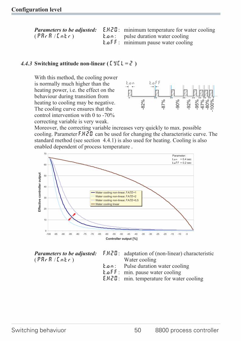
With this method, the cooling poweris normally much higher than theheating power, i.e. the effect on thebehaviour during transition fromheating to cooling may be negative.The cooling curve ensures that thecontrol intervention with 0 to -70%correcting variable is very weak.Moreover, the correcting variable increases very quickly to max. possiblecooling. Parameter F.H2O can be used for changing the characteristic curve. Thestandard method (see section 4.4.1) is also used for heating. Cooling is alsoenabled dependent of process temperature .
Parameters to be adjusted: F.H2O: adaptation of (non-linear) characteristic( PArA / Cntr) Water cooling
t.on: Pulse duration water coolingt.off: min. pause water coolingE.H2O: min. temperature for water cooling
Configuration level
Switching behaviuor 50 8800 process controller
-95
%
-67
%-8
0%
-10
0%
-92
%
-90
%
-87
%
-82
%
t.offt.on
0
10
20
30
40
50
60
70
-100 -95 -90 -85 -80 -75 -70 -65 -60 -55 -50 -45 -40 -35 -30 -25 -20 -15 -10 -5
Controller output [%]
Water cooling non-linear, =1F.H2O
Water cooling non-linear, =2F.H2O
Water cooling non-linear, =0,5F.H2O
Water cooling linear
Parameter:
t.on = 0.4 sec
t.off = 0.2 sec
Eff
ec
tiv
ec
on
tro
lle
ro
utp
ut
4.4.4 Heating and cooling with constant period ( CyCl= 3 )
1 and t2 are met in the overalloutput range . To preventunreasonably short pulses, parametertp is used for adjusting the shortestpulse duration. With small correctingvalues which require a pulse shorterthan the value adjusted in tp, thispulse is suppressed. However, thecontroller stores the pulse andtotalizes further pulses, until a pulseof duration tp can be output.
Parameters to be adjusted: t1 : Min. cycle time 1 (heating) [s]( PArA/ Cntr) t2 : min. cycle time 2 (cooling) [s]
tp: min. pulse length [s]
Configuration level
8800 process controller 51 Switching behaviuor
50%
50%
t1 t2/
tp
tp
30%
70%
20%
80%
10%
90%
t1 t2/
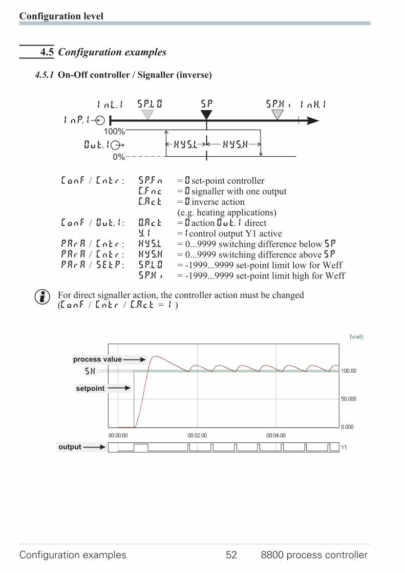
4.5 Configuration examples
4.5.1 On-Off controller / Signaller (inverse)
ConF / Cntr: SP.Fn = 0set-point controllerC.Fnc = 0signaller with one outputC.Act = 0inverse action
(e.g. heating applications)ConF / Out.1: O.Act = 0action Out.1 direct
Y.1 =1control output Y1 activePArA / Cntr: Hys.l = 0...9999 switching difference below SP
PArA / Cntr: Hys.H = 0...9999 switching difference above SPPArA / SEtP: SP.LO = -1999...9999 set-point limit low for Weff
SP.Hi = -1999...9999 set-point limit high for Weff
g For direct signaller action, the controller action must be changed(ConF / Cntr / C.Act = 1 )
Configuration level
Configuration examples 52 8800 process controller
InH.1InL.1 SP.LO SP SP.Hi
100%
0%
Out.1Â
InP.1Ê
HYS.HHYS.L
setpoint
output
process value
SH
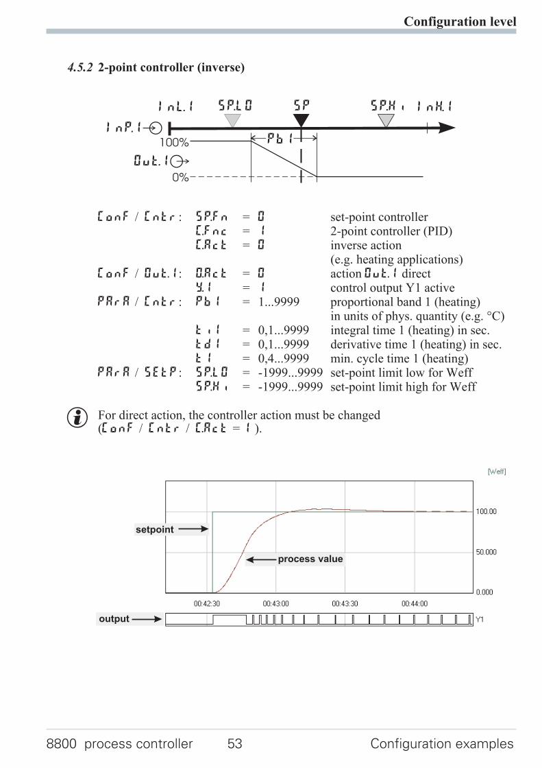
4.5.2 2-point controller (inverse)
ConF / Cntr: SP.Fn = 0 set-point controllerC.Fnc = 1 2-point controller (PID)C.Act = 0 inverse action
(e.g. heating applications)ConF / Out.1: O.Act = 0 action Out.1 direct
Y.1 = 1 control output Y1 activePArA / Cntr: Pb1 = 1...9999 proportional band 1 (heating)
in units of phys. quantity (e.g. °C)ti1 = 0,1...9999 integral time 1 (heating) in sec.td1 = 0,1...9999 derivative time 1 (heating) in sec.t1 = 0,4...9999 min. cycle time 1 (heating)
PArA / SEtP: SP.LO = -1999...9999 set-point limit low for WeffSP.Hi = -1999...9999 set-point limit high for Weff
g For direct action, the controller action must be changed(ConF / Cntr / C.Act = 1 ).
Configuration level
8800 process controller 53 Configuration examples
InH.1InL.1 SP.LO SP SP.Hi
Out.1Â
InP.1Ê100%
0%
PB1
setpoint
output
process value
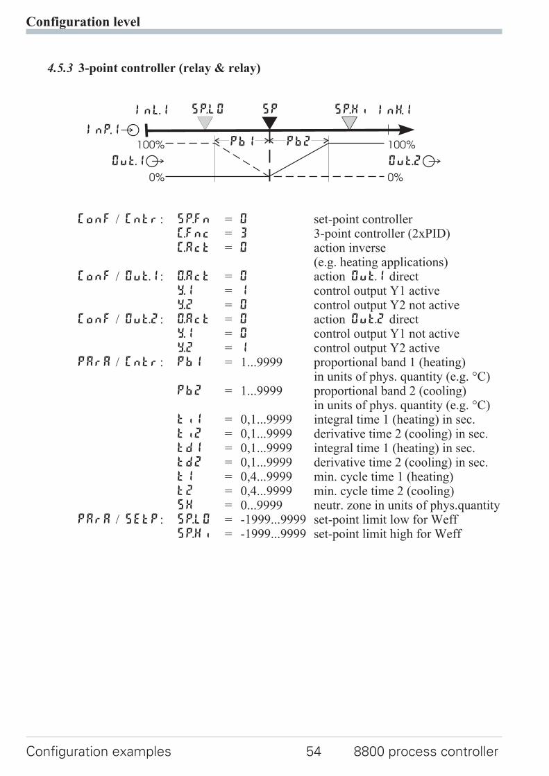
4.5.3 3-point controller (relay & relay)
ConF / Cntr: SP.Fn = 0 set-point controllerC.Fnc = 3 3-point controller (2xPID)C.Act = 0 action inverse
(e.g. heating applications)ConF / Out.1: O.Act = 0 action Out.1 direct
Y.1 = 1 control output Y1 activeY.2 = 0 control output Y2 not active
ConF / Out.2: O.Act = 0 action Out.2 directY.1 = 0 control output Y1 not activeY.2 = 1 control output Y2 active
PArA / Cntr: Pb1 = 1...9999 proportional band 1 (heating)in units of phys. quantity (e.g. °C)
Pb2 = 1...9999 proportional band 2 (cooling)in units of phys. quantity (e.g. °C)
ti1 = 0,1...9999 integral time 1 (heating) in sec.ti2 = 0,1...9999 derivative time 2 (cooling) in sec.td1 = 0,1...9999 integral time 1 (heating) in sec.td2 = 0,1...9999 derivative time 2 (cooling) in sec.t1 = 0,4...9999 min. cycle time 1 (heating)t2 = 0,4...9999 min. cycle time 2 (cooling)SH = 0...9999 neutr. zone in units of phys.quantity
PArA / SEtP: SP.LO = -1999...9999 set-point limit low for WeffSP.Hi = -1999...9999 set-point limit high for Weff
Configuration level
Configuration examples 54 8800 process controller
InH.1InL.1 SP.LO SP SP.Hi
Out.1Â
InP.1Ê100%
0%
100%
0%
PB1 PB2
Out.2Â
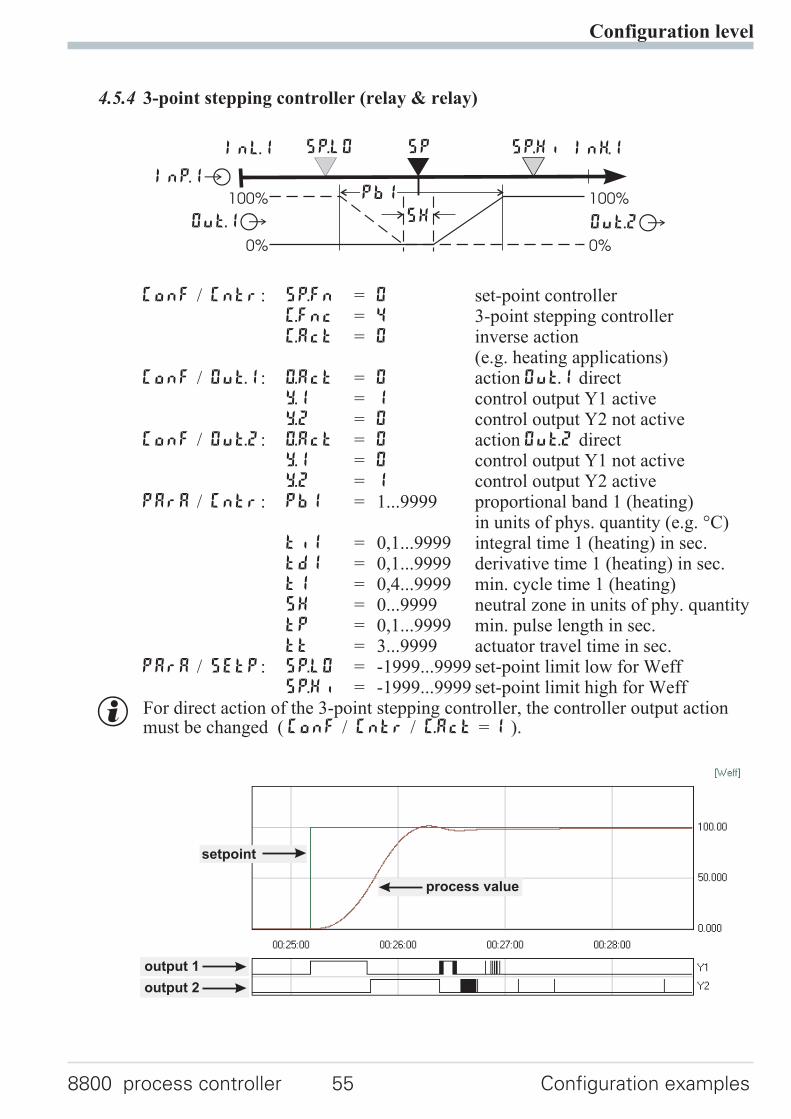
4.5.4 3-point stepping controller (relay & relay)
ConF / Cntr: SP.Fn = 0 set-point controllerC.Fnc = 4 3-point stepping controllerC.Act = 0 inverse action
(e.g. heating applications)ConF / Out.1: O.Act = 0 action Out.1 direct
Y.1 = 1 control output Y1 activeY.2 = 0 control output Y2 not active
ConF / Out.2: O.Act = 0 action Out.2 directY.1 = 0 control output Y1 not activeY.2 = 1 control output Y2 active
PArA / Cntr: Pb1 = 1...9999 proportional band 1 (heating)in units of phys. quantity (e.g. °C)
ti1 = 0,1...9999 integral time 1 (heating) in sec.td1 = 0,1...9999 derivative time 1 (heating) in sec.t1 = 0,4...9999 min. cycle time 1 (heating)SH = 0...9999 neutral zone in units of phy. quantitytP = 0,1...9999 min. pulse length in sec.tt = 3...9999 actuator travel time in sec.
PArA / SEtP: SP.LO = -1999...9999 set-point limit low for WeffSP.Hi = -1999...9999 set-point limit high for Weff
g For direct action of the 3-point stepping controller, the controller output actionmust be changed ( ConF / Cntr / C.Act = 1 ).
Configuration level
8800 process controller 55 Configuration examples
InH.1InL.1 SP.LO SP SP.Hi
Out.1Â
InP.1Ê
Out.2Â
100%
0%
100%
0%
PB1
SH
setpoint
output 1
process value
output 2
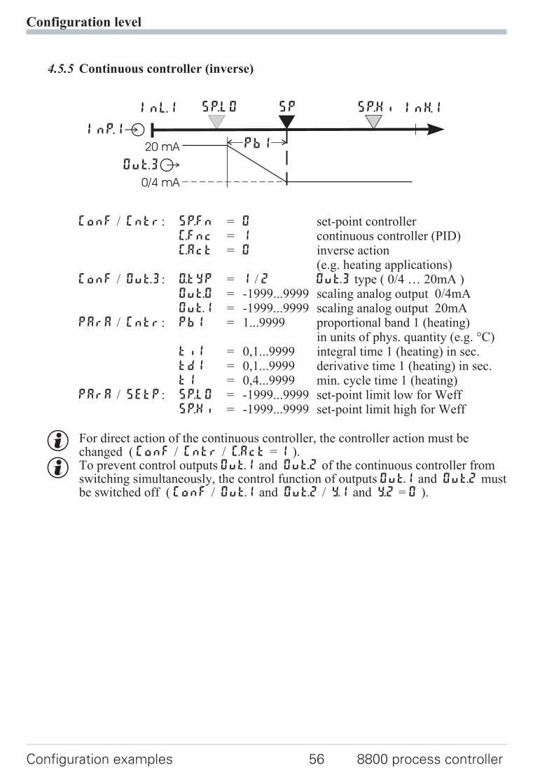
4.5.5 Continuous controller (inverse)
ConF / Cntr: SP.Fn = 0 set-point controllerC.Fnc = 1 continuous controller (PID)C.Act = 0 inverse action
(e.g. heating applications)ConF / Out.3: O.tYP = 1 / 2 Out.3 type ( 0/4 … 20mA )
Out.0 = -1999...9999 scaling analog output 0/4mAOut.1 = -1999...9999 scaling analog output 20mA
PArA / Cntr: Pb1 = 1...9999 proportional band 1 (heating)in units of phys. quantity (e.g. °C)
ti1 = 0,1...9999 integral time 1 (heating) in sec.td1 = 0,1...9999 derivative time 1 (heating) in sec.t1 = 0,4...9999 min. cycle time 1 (heating)
PArA / SEtP: SP.LO = -1999...9999 set-point limit low for WeffSP.Hi = -1999...9999 set-point limit high for Weff
g For direct action of the continuous controller, the controller action must bechanged ( ConF / Cntr / C.Act = 1 ).
g To prevent control outputs Out.1 and Out.2 of the continuous controller fromswitching simultaneously, the control function of outputs Out.1 and Out.2 mustbe switched off ( ConF / Out.1 and Out.2 / Y.1 and Y.2 = 0 ).
Configuration level
Configuration examples 56 8800 process controller
InH.1InL.1 SP.LO SP SP.Hi
Out.3Â
InP.1Ê20 mA
0/4 mA
PB1
4.5.6 ∆ - Y - Off controller / 2-point controller with pre-contact
ConF / Cntr: SP.Fn = 0 set-point controller
C.Fnc = 2 ∆ -Y-Off controllerC.Act = 0 inverse action
(e.g. heating applications)ConF / Out.1: O.Act = 0 action Out.1 direct
Y.1 = 1 control output Y1 activeY.2 = 0 control output Y2 not active
ConF / Out.2: O.Act = 0 action Out.2 directY.1 = 0 control output Y1 not activeY.2 = 1 control output Y2 active
PArA / Cntr: Pb1 = 1...9999 proportional band 1 (heating)in units of phys. quantity (e.g. °C)
ti1 = 0,1...9999 integral time 1 (heating) in sec.td1 = 0,1...9999 derivative time 1 (heating) in sec.t1 = 0,4...9999 min. cycle time 1 (heating)SH = 0...9999 switching difference
d.SP = -1999...9999 trigg. point separation suppl. cont.
∆ / Y / Off in units of phys. quantityPArA / SEtP: SP.LO = -1999...9999 set-point limit low for Weff
SP.Hi = -1999...9999 set-point limit high for Weff
Configuration level
8800 process controller 57 Configuration examples
InH.1InL.1 SP.LO SP SP.Hi
Out.1Â
InP.1Ê100%
0%
PB1
Out.2Âd.SPSH
4.5.7 8800 process controller with measured value output
ConF / Out.3 / 4: O.tYP = 1 Out.3/ 4 0...20mA continuous= 2 Out.3/ 4 4...20mA continuous= 3 Out.3/ 4 0...10V continuous= 4 Out.3/ 4 2...10V continuous
Out.0 = -1999...9999 scaling Out.3/ 4for 0/4mA or 0/2V
Out.1 = -1999...9999 scaling Out.3/ 4for 20mA or 10V
O.Src = 3 signal source for Out.3/ 4 isthe process value
Configuration level
Configuration examples 58 8800 process controller
phys.quantity
mA / Vphys. quantity
Out.1
Out.0
0/4mA0/2V
20mA10V
1
456
789
10
1
2
3
4
5
6
7
8
9
10
11
12
13
14
17
(16)
+
L
N2
3
90...250VAC24VUC
U
U
11
12
13
14
15
OUT3
OUT4INP1
15
4.5.8 Continuous controller with integrated positioner ( Cntr/ C.Fnc = 6 )
This is basically a cascade. A tracking controller with three-point steppingbehaviour which operates with Yp as process value (INP.2 / INP.3) is used withthe continuous controller.
ConF / Cntr SP.Fn = 0 Setpoint controllerC.Fnc = 6 Continuous controller with
integrated positionerC.Act = 0 Direction of operation invers
(e.g. heating)
ConF / InP.2: I.Fnc = 3 Position featback Yp
S.typ = 50 Sensor e.g. potentiometer 0..160 ΩConF / Out.1: O.Act = 0 Direction of operation Out.1 direct
Y.1 = 1 Controller output Y1 activY.2 = 0 Controller output Y2 not activ
ConF / Out.2: O.Act = 0 Direction of operation Out.2 directY.1 = 0 Controller output Y1 not activY.2 = 1 Controller output Y2 activ
PArA / Cntr: Pb1 = 0,1...9999 Proportional band 1 (heating)in phys. units (e.g. °C)
ti1 = 1...9999 Integral action time 1 (heating)in sec.
td1 = 1...9999 Derivative action time t 1 (heating)in sec.
t1 = 0,4...9999 Minimal cycle time 1 (heating)SH = 0...9999 Neutral zone in phys. units (e.g.°C)
Configuration level
8800 process controller 59 Configuration examples
W
X M
OUT.4
OUT.1
OUT.2
INP.2
Ypid
Position controller
INP.1
Y.1
Y.2
Master controller
YcontinuousX
W
SP
5 Parameter setting level
5.1 Parameter survey
Adjustment:
w The parameters can be adjusted by means of keys ÈÌ
w Transition to the next parameter is by pressing key Ù
w After the last parameter of a group, donE is displayed, followed byautomatic change to the next group.
g Return to the beginning of a group is by pressing the Ù key for 3 sec.If for 30 sec. no keypress is excecuted the controler returns to the processvalue and setpoint display ( Time Out = 30 sec. )
Parameter setting level
Parameter survey 60 8800 process controller
PArA Parameter setting level
È
Ì
Cntr
Con
trol
and
self
-tun
ing
PAr.2
2.se
tof
para
met
ers
SEtP
Set-
poin
tan
dpr
oces
sva
lue
InP.1
Inpu
t1
InP.2
Inpu
t2
InP.3
Inpu
t3
Lim
Lim
itva
lue
func
tion
s
End
Pb1 Pb12 SP.Lo InL.1 Inl.2 InL.3 L.1
Pb2 Pb22 SP.Hi OuL.1 OuL.2 OuL.3 H.1
ti1 ti12 SP.2 InH.1 InH.2 InH.3 HYS.1
ti2 ti22 r.SP OuH.1 OuH.2 OuH.3 dEl.1
td1 td12 tF.1 tF.2 tF.3 L.2
td2 td22 E.tc E.tc H.2
t1 HYS.2
t2 dEl.2
SH L.3
Hys.l H.3
Hys.H HYS.3
d.SP dEl.3
tP HC.A
tt
Y.Lo
Y.Hi
Y2
Y0
Ym.H
L.Ym
E.H2O
t.on
t.off
FH2
oFFS
tEmp
5.2 Parameters
1 Valid for ConF/ othr/ dP = 0. With dP = 1 / 2 / 3 also 0,1 / 0,01 /0,001 is possible.
Parameter setting level
8800 process controller 61 Parameters
Cntr
Name Value range Description Default
Pb1 1...99991 Proportional band 1 (heating) in phys. dimensions (e.g. °C) 100
Pb2 1...99991 Proportional band 2 (cooling) in phys. dimensions (e.g. °C) 100
ti1 0,1...9999 Integral action time 1 (heating) [s] 180
ti2 0,1...9999 Integral action time 2 (cooling) [s] 180
td1 0,1...9999 Derivative action time 1 (heating) [s] 180
td2 0,1...9999 Derivative action time 2 (cooling) [s] 180
t1 0,4...9999 Minimal cycle time 1 (heating) [s]. The minimum impulse is1/4 x t1
10
t2 0,4...9999 Minimal cycle time 2 (heating) [s]. The minimum impulse is1/4 x t2
10
SH 0...9999 Neutral zone or switching differential for on-off control[phys. dimensions)
2
Hys.l 0...9999 Switching difference Low signaller [engineering unit] 1
Hys.H 0...9999 Switching difference High signaller [engineering unit] 1
d.SP -1999...9999 Trigger point seperation for additional contact ∆ / Y / Off[phys. dimensions]
100
tP 0,1...9999 Minimum impulse [s] OFF
tt 3...9999 Motor travel time [s] 60
Y2 -100...100 2. correcting variable 0
Y.Lo -120...120 Lower output limit [%] 0
Y.Hi -120...120 Upper output limit [%] 100
Y2 -100...100 2. correcting variable 0
Y.0 -100...100 Working point for the correcting variable [%] 0
Ym.H -100...100 Limitation of the mean value Ym [%] 5
L.Ym 0...9999 Max. deviation xw at the start of mean value calculation[phys. dimensions]
8
E.H2O -1999...9999 Min. temperature for water cooling. Below the settemperature no water cooling happens
0
t.on 0,1...9999 Impulse lenght for water cooling. Fixed for all values ofcontroller output.The pause time is varied.
1
t.oFF 1...9999 Min. pause time for water cooling. The max. effectivecontroller output results fromt.on/(t.on+t.off)·100%
10
F.H2O 0,1...9999 Modification of the (non-linear) water cooling characteristic(see page 50)
1
oFFS -120...120 Zero offset 0
tEmp 0...9999 Sensor temperature (in engineering units e.g. °C)With oxygen measurement (O2) (see page 70)
750
1 Valid for ConF/ othr/ dP = 0. With dP = 1 / 2 / 3 also 0,1 / 0,01 /0,001 is possible.
Parameter setting level
Parameters 62 8800 process controller
PAr.2
Name Value range Description Default
Pb12 1...9999 1 Proportional band 1 (heating) in phys. dimensions (e.g. °C),2. parameter set
100
Pb22 1...9999 1 Proportional band 2 (cooling) in phys. dimensions (e.g. °C),2. parameter set
100
Ti22 0,1...9999 Integral action time 2 (cooling) [s], 2. parameter set 180
Ti12 0,1...9999 Integral action time 1 (heating) [s], 2. parameter set 180
Td12 0,1...9999 Derivative action time 1 (heating) [s], 2. parameter set 180
Td22 0,1...9999 Derivative action time 2 (cooling) [s], 2. parameter set 180
SEtP
Name Value range Description Default
SP.LO -1999...9999 Set-point limit low for Weff -100
SP.Hi -1999...9999 Set-point limit high for Weff 1200
SP.2 -1999...9999 Set-point 2. 0
r.SP 0...9999 Set-point gradient [/min] OFF
SP -1999...9999 Set-point (only visible with 8800/8840 configurator!) 0
SP.LO and SP.Hi should be within the limits of rnGH and rnGL see
configuration r Controller page17
InP.1
Name Value range Description Default
InL.1 -1999...9999 Input value for the lower scaling point 0
OuL.1 -1999...9999 Displayed value for the lower scaling point 0
InH.1 -1999...9999 Input value for the upper scaling point 20
OuH.1 -1999...9999 Displayed value for the lower scaling point 20
t.F1 0,0...9999 Filter time constant [s] 0,5
Etc.1 0...100 (°C)32...212 (°F)
External cold-junction reference temperature (external TC) OFF
InP.2
Name Value range Description Default
InL.2 -1999...9999 Input value for the lower scaling point 0
OuL.2 -1999...9999 Displayed value for the lower scaling point 0
InH.2 -1999...9999 Input value for the upper scaling point 50
OuH.2 -1999...9999 Displayed value for the upper scaling point 50
g Resetting the controller configuration to factory setting (Default)r chapter 11.1 (page 82)
Parameter setting level
8800 process controller 63 Parameters
Name Value range Description Default
t.F2 0,0...999,9 Filter time constant [s] 0,5
InP.3
Name Value range Description Default
InL.3 -1999...9999 Input value for the lower scaling point 0
OuL.3 -1999...9999 Displayed value for the lower scaling point 0
InH.3 -1999...9999 Input value for the upper scaling point 20
OuH.3 -1999...9999 Displayed value for the upper scaling point 20
t.F3 0,0...999,9 Filter time constant [s] 0,5
Etc.3 0...100 (°C)32...212 (°F
External cold-junction reference temperature (external TC) OFF
Lim
Name Value range Description Default
L.1 -1999...9999 Lower limit 1 -10
H.1 -1999...9999 Upper limit 1 10
HYS.1 0...9999 Hysteresis limit 1 1
dEl.1 0...9999 Alarm delay from limit value 1 0
L.2 -1999...9999 Lower limit 2 OFF
H.2 -1999...9999 Upper limit 2 OFF
HYS.2 0...9999 Hysteresis limit 2 1
dEl.2 0...9999 Alarm delay from limit value 2 0
L.3 -1999...9999 Lower limit 3 OFF
H.3 -1999...9999 Upper limit 3 OFF
HYS.3 0...9999 Hysteresis limit 3 1
dEl.3 0...9999 Alarm delay from limit value 3 0
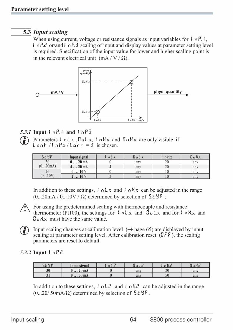
5.3 Input scalingWhen using current, voltage or resistance signals as input variables for InP.1,InP.2 or/and InP.3 scaling of input and display values at parameter setting levelis required. Specification of the input value for lower and higher scaling point is
in the relevant electrical unit (mA / V / Ω).
5.3.1 Input Inp.1 and InP.3
g Parameters InL.x , OuL.x, InH.x and OuH.x are only visible ifConF / InP.x / Corr = 3 is chosen.
In addition to these settings, InL.x and InH.x can be adjusted in the range
(0...20mA / 0...10V / Ω) determined by selection of S.tYP .
a For using the predetermined scaling with thermocouple and resistancethermometer (Pt100), the settings for InL.x and OuL.x and for InH.x andOuH.x must have the same value.
g Input scaling changes at calibration level (r page 65) are displayed by inputscaling at parameter setting level. After calibration reset (OFF), the scalingparameters are reset to default.
5.3.2 Input InP.2
In addition to these settings, InL.2 and InH.2 can be adjusted in the range
(0...20/ 50mA/Ω) determined by selection of S.tYP.
Parameter setting level
Input scaling 64 8800 process controller
mA/V
phys.quantity
mA / V phys. quantity
OuH.x
OuL.x
InH.xInL.x
S.tYP Input signal InL.x OuL.x InH.x OuH.x30
(0...20mA)0 … 20 mA 0 any 20 any4 … 20 mA 4 any 20 any
40(0...10V)
0 … 10 V 0 any 10 any2 … 10 V 2 any 10 any
S.tYP Input signal InL.2 OuL.2 InH.2 OuH.2
30 0 … 20 mA 0 any 20 any31 0 … 50 mA 0 any 50 any
6 Calibration level
Measured value correction ( CAL) is only visible if ConF / InP.1 / Corr = 1or 2 is chosen.
The measured value can be matched in the calibration menu ( CAL). Twomethods are available:
Offset correction( ConF/ InP.1 / Corr =1 ):
w possible on-line at theprocess
2-point correction( ConF/ InP.1 / Corr = 2 ):
w is possible off-line withprocess value simulator
Calibration level
8800 process controller 65
X
standard setting
offset correction
InL.1
OuL.1new
display
OuL.1old
X
standard setting
2-point correction
InL.1 InH.1
OuL.1new
OuH.1new
display
OuH.1old
OuL.1old
Offset correction ( ConF/ InP.1 / Corr =1 ):
InL.1: The input value of the scaling point is displayed.The operator must wait, until the process is at rest.Subsequently, the operator acknowledges the input value by pressing
key Ù.OuL.1: The display value of the scaling point is displayed.
Before calibration, OuL.1 is equal to InL.1.
The operator can correct the display value by pressing keys ÈÌ .
Subsequently, he confirms the display value by pressing key Ù.
Calibration level
66 8800 process controller
r
ÌÙ
3 sec.
r PArA
CALrÙr InP.1 Ùr InL.1r r Ù
r
:
OuL.1r r Ù
Endr r Ù
ÌÈ
12001199°C°F
SP.2SP.E
parafuncAda
Err
2-point correction ( ConF/ InP.1 / Corr = 2):
InL.1: The input value of the lower scaling point is displayed.The operator must adjust the lower input value by means of a
process value simulator and confirm the input value by pressing key Ù.OuL.1: The display value of the lower scaling point is displayed.
Before calibration, OuL.1 equals InL.1.
The operator can correct the lower display value by pressing the ÈÌkeys. Subsequently, he confirms the display value by pressing key Ù.
InH.1: The input value of the upper scaling point is displayed. .The operator must adjust the upper input value by means of the
process value simulator and confirm the input value by pressing key Ù.OuH.1: The display value of the upper scaling point is displayed.
Before calibration OuH.1 equals InH.1.
The operator can correct the upper display value by pressing keys ÈÌSubsequently, he confirms the display value by pressing key Ù.
g The parameters (OuL.1, OuH.1) changed at CAL level can be reset by adjustingthe parameters below the lowest adjustment value (OFF) by means of decrementkey Ì .
Calibration level
8800 process controller 67
12001199°C°F
SP.2SP.E
parafuncAda
Err
r
Ì
Ù3 sec.
r PArA
CALrÙr InP.1 Ùr r r Ù
Ù
InL.1
È
InL1
Ù
OuL.1 rÙÌÈ
r ÙInH.1
È
InH.1
Ù
OuH.1 rÙÌÈ
ConFr
Ì
r
ÌÈ
InP.2
InP.3
ÌÈ
End
ÌÈ
7 Special functions
7.1 DAC®– motor actuator monitoring
(Digital Actor Control DAC®)
With all controllers with position feedback Yp, the motor actuator can bemonitored for functional troubles. The DAC® function can be started by chosingthe parameter C.Fnc = 5 or 6 at the configuration level ( ConF):
w ConF / Cntr / C.Fnc = 5 3-point-stepping controller withposition feedback Yp as potentiometer
w ConF / Cntr / C.Fnc = 6 Continuous controller with integratedpositioner and position feedback Yp aspotentiometer
If an error occurs, the controller switches to manual operation (ò - LED blinks)and no impulses are given out any longer. If one of the relays switches when a
DAC® error occurs, parameter dAC.A = 1 and inverse action O.Act = 1 mustbe selected for the relevant output OUT.1 … OUT.4 in the ConF menu
( OUt.3 and 4 only possible if O.tYP = 0 [relay/logic]):
w ConF / OUt.x / dAc.A = 1 Motor actuator monitoring (DAC) aktive
The system detects the following stepping controller errors:
w defective motor
w defective capacitor (wrong rotating direction)
w wrong phase followers (wrong rotating direction)
w defective force transmission at spindle or drive
w excessive backlash due to wear
w jamming of the control valve e.g. due to foreign body
In these cases the controller will change to manual operation and the outputs willbe switched off. Is the controller switched to automatic operation again or anymodification is done the controller activates the DAC function again and theoutputs will be setted.
Resetting of a DAC error:
After solving the technical problem the DAC errror can be acknowledged in theerror list. Thereafter the controller works again in normal operation mode.
See also chapter 3.4 "Mainenance manager / Error list", page 12 ff.
Special functions
DAC®
– motor actuator monitoring 68 8800 process controller

Functioning of the DAC function
No input filter should be defined for the Yp input ( PArA / InP.x / t.Fx = 0 ).Therewith no wrong detection of blocking or wrong method of operation can berecognized.The automatic calibration can be used with drives outfitted with spring assembly.
Execution of the calibration:It is controlled if the mean alteration between two messurements is enough forthe DAC monitoring. The calibration will be stopped if the alteration betweentwo messurements is too small.The position of 0% is searched. Therefor the drive will be closed until there is nochanging of the input signal for 0,5 sec.Assuming that the drive is outfitted with spring assembly, the drive is opened for2,8 sec. The drive should then still be within the spring assembly. This position isallocated and stored as 0%.With the same procedure the position for 100% is allocated and stored.Simultaneously the motor running time is determined and saved as parameter tt.Afterwards the controller sets the drive in the position before calibration.Was the controller in automatic mode before calibration it will be set to automaticmode again otherwise it remains in manual mode.
The following errors can be occure during calibration:
w the change of the Yp input is to small, no monitoring is possible
w the motion is in wrong direction
w the Yp input is broken
In these cases the automatic calibration will be stopped and the controller remainsin manual mode.
g If the automatic calibration leads to no resonable results the calibration of the Ypinput can be done manual.
g If the conroller reaches the positions of 0% or 100% the outputs will be switchedoff. Also in manual mode it is not possible to exceed these limits.
g Because no controller with continuouse output and Yp input is defined therewon't be the DAC function for this controlling type.
Special functions
8800 process controller 69 DAC®
– motor actuator monitoring
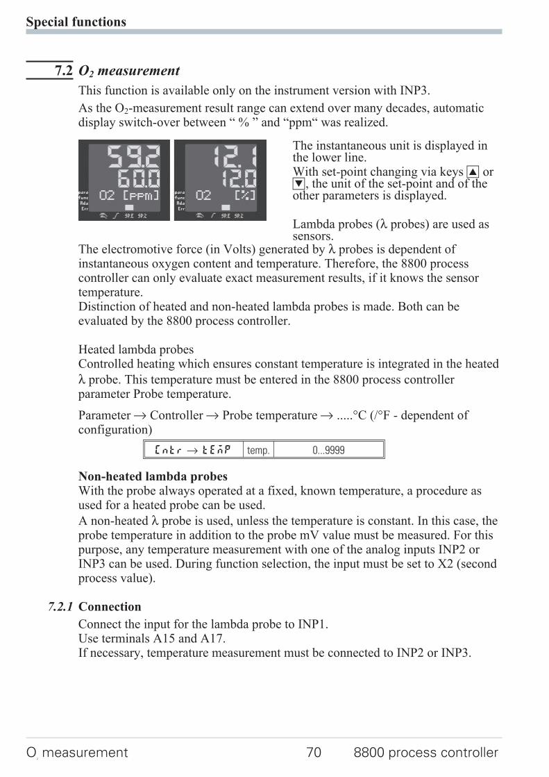
7.2 O2 measurement
This function is available only on the instrument version with INP3.
As the O2-measurement result range can extend over many decades, automaticdisplay switch-over between “ % ” and “ppm“ was realized.
The instantaneous unit is displayed inthe lower line.With set-point changing via keys I orD, the unit of the set-point and of theother parameters is displayed.
Lambda probes (λ probes) are used assensors.
The electromotive force (in Volts) generated by λ probes is dependent ofinstantaneous oxygen content and temperature. Therefore, the 8800 processcontroller can only evaluate exact measurement results, if it knows the sensortemperature.Distinction of heated and non-heated lambda probes is made. Both can beevaluated by the 8800 process controller.
Heated lambda probesControlled heating which ensures constant temperature is integrated in the heated
λ probe. This temperature must be entered in the 8800 process controllerparameter Probe temperature.
Parameter r Controller r Probe temperature r .....°C (/°F - dependent ofconfiguration)
Cntrr tEmP temp. 0...9999
Non-heated lambda probesWith the probe always operated at a fixed, known temperature, a procedure asused for a heated probe can be used.
A non-heated λ probe is used, unless the temperature is constant. In this case, theprobe temperature in addition to the probe mV value must be measured. For thispurpose, any temperature measurement with one of the analog inputs INP2 orINP3 can be used. During function selection, the input must be set to X2 (secondprocess value).
7.2.1 Connection
Connect the input for the lambda probe to INP1.Use terminals A15 and A17.If necessary, temperature measurement must be connected to INP2 or INP3.
Special functions
O2measurement 70 8800 process controller
7.2.2 Configuration:
Oxygen measurementOxygen measurement with heated lambda probe
Controller r Process value processing r 7: O2 functions with constant probetemperature
Cntrr C.tYP 7 O2-const
Oxygen measurement with non-heated lambda probe
Controller r Process value processing r O2 functions with measured probetemperature
Cntrr C.tYP 8 O2+temp
Input 1 r Function INP1 r 7: process value X1
InP.1 r 1.Fnc 7 X1-Input
In input 1, the sensor type is set for one of the high-impedance voltage inputs:
Input 1 r Sensor type r 42: special (-25...1150 mV) or41: special (-2,5...115 mV)
InP.1 r S.tyP 41 115 mV
InP.1 r S.tyP 42 1150 mV
Input 1 r meas. value correction r 0: no correction
InP.1 r S.Lin 0 no
Temperature measurement (required with non-heated lambda probe)Any temperature measurement with one of analog inputs INP2 or INP3 can beused. Select input X2 during function selection (second set-point).
g With O2 measurement, evaluation in ppm or % must be specified for allparameters related to the process value.This is done centrally during configuration.
Other r Parameter unit for O2r 0: parameter for O2 function in ppm1: parameter for O2 function in %
othrr O2 0 unit : ppm
othrr O2 1 unit : %
g Whether the temperature of the non-heated λ probe is specified in °C or °F canbe selected during configuration.Other r Unit r 1: in Celsius
2: in Fahrenheit
othrr Unit 1 °C
othrr Unit 2 °F
Special functions
8800 process controller 71 O2measurement
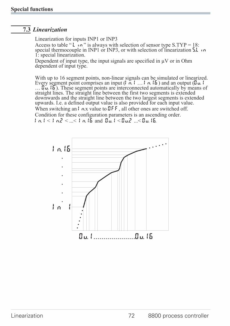
7.3 Linearization
Linearization for inputs INP1 or INP3Access to table “ Lin” is always with selection of sensor type S.TYP = 18:special thermocouple in INP1 or INP3, or with selection of linearization S.Lin1: special linearization.Dependent of input type, the input signals are specified in µV or in Ohmdependent of input type.
With up to 16 segment points, non-linear signals can be simulated or linearized.Every segment point comprises an input (In.1 … In.16) and an output (Ou.1… Ou.16). These segment points are interconnected automatically by means ofstraight lines. The straight line between the first two segments is extendeddownwards and the straight line between the two largest segments is extendedupwards. I.e. a defined output value is also provided for each input value.When switching an In.x value to OFF, all other ones are switched off.Condition for these configuration parameters is an ascending order.In.1 < In.2 < ...< In.16 and Ou.1 < Ou.2 ...< Ou.16.
Special functions
Linearization 72 8800 process controller
In.16
In 1
.
.
.
.
.
.
Ou.1 Ou.16.....................
7.4 8800 process controller as Modbus master
a This function is only selectable with 8800/8840 configurator (engineering tool)!
The 8800 process controller can be used as Modbus master ( ConF / othr /MASt = 1 ). The Modbus master sends ist data to all slaves (Broadcast message,controller adress 0). It transmits its data (modbus adress AdrU) cyclic with thecycle time Cycl to the bus. The slave controller receives the data transmitted bythe masters and allocates it to the modbus target adress AdrO. If more than onedata should be transmitted by the master controller ( Numb > 1) , the modbusadress AdrU indicates the start adress of the data that should be transmitted andAdrO indicates the first target adress where the received data should be stored.The following data will be stored at the logically following modbus targetadresses.With this it is possible e.g. to specify the process value of the master controller asset-point for the slave controllers.
Special functions
8800 process controller 73 8800 process controller as Modbus master
Additions othr (only visible with 8800/8840 configurator!)
Name Value range Description Default
MASt Controller is used as Modbus master 0
0 Slave
1 Master
Cycl 0...200 Cycle time [ms] for the Modbus master to transmit its datato the bus.
60
AdrO 1...65535 Target address to which the with AdrU specified data isgiven out on the bus.
1
AdrU 1...65535 Modbus address of the data that Modbus master gives tothe bus.
1
Numb 0...100 Number of data that should be transmitted by the Modbusmaster.
0
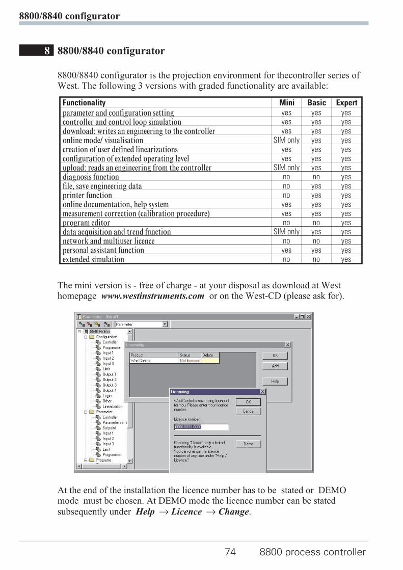
8 8800/8840 configurator
8800/8840 configurator is the projection environment for thecontroller series ofWest. The following 3 versions with graded functionality are available:
The mini version is - free of charge - at your disposal as download at Westhomepage www.westinstruments.com or on the West-CD (please ask for).
At the end of the installation the licence number has to be stated or DEMOmode must be chosen. At DEMO mode the licence number can be stated
subsequently under Help r Licence r Change.
8800/8840 configurator
74 8800 process controller
Functionality Mini Basic Expert
parameter and configuration setting yes yes yescontroller and control loop simulation yes yes yesdownload: writes an engineering to the controller yes yes yesonline mode/ visualisation SIM only yes yescreation of user defined linearizations yes yes yesconfiguration of extended operating level yes yes yesupload: reads an engineering from the controller SIM only yes yesdiagnosis function no no yesfile, save engineering data no yes yesprinter function no yes yesonline documentation, help system yes yes yesmeasurement correction (calibration procedure) yes yes yesprogram editor no no yesdata acquisition and trend function SIM only yes yesnetwork and multiuser licence no no yespersonal assistant function yes yes yesextended simulation no no yes
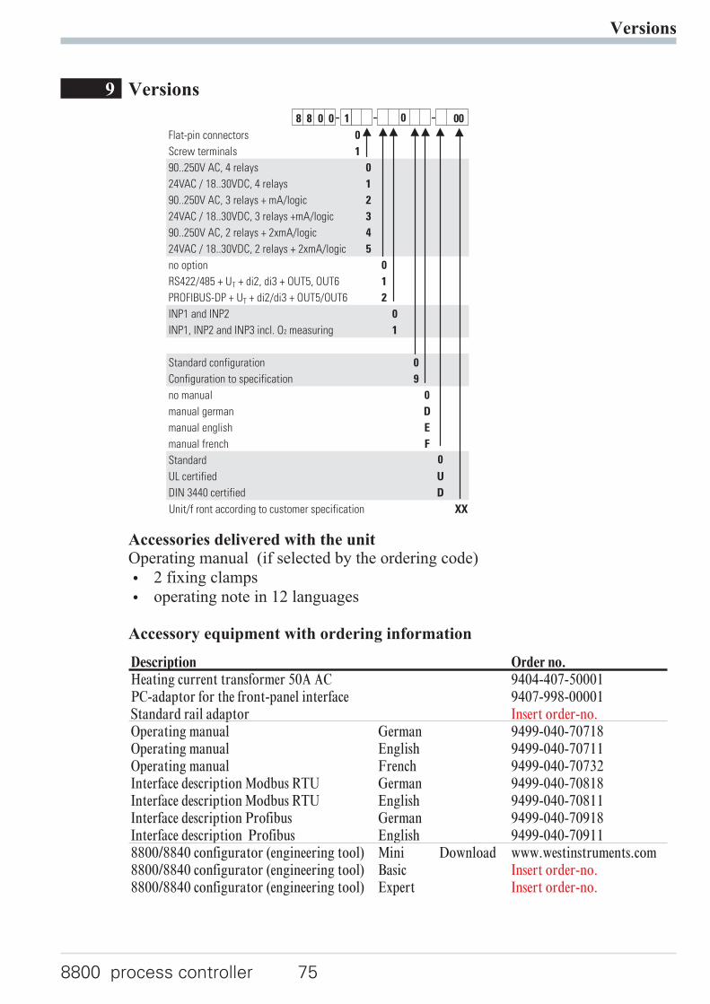
9 Versions
Accessories delivered with the unitOperating manual (if selected by the ordering code)
w 2 fixing clamps
w operating note in 12 languages
Accessory equipment with ordering information
Versions
8800 process controller 75
8 8 0 0 1 00
Flat-pin connectors 0
Screw terminals 1
90..250V AC, 4 relays 0
24VAC / 18..30VDC, 4 relays 1
90..250V AC, 3 relays + mA/logic 2
24VAC / 18..30VDC, 3 relays +mA/logic 3
90..250V AC, 2 relays + 2xmA/logic 4
24VAC / 18..30VDC, 2 relays + 2xmA/logic 5
no option 0
RS422/485 + UT + di2, di3 + OUT5, OUT6 1
PROFIBUS-DP + UT + di2/di3 + OUT5/OUT6 2
INP1 and INP2 0
INP1, INP2 and INP3 incl. O measuring2 1
0
Standard configuration 0
Configuration to specification 9
no manual 0
manual german D
manual english E
manual french F
Standard 0
UL certified U
DIN 3440 certified D
Unit/f ront according to customer specification XX
Description Order no.Heating current transformer 50A AC 9404-407-50001PC-adaptor for the front-panel interface 9407-998-00001Standard rail adaptor Insert order-no.Operating manual German 9499-040-70718Operating manual English 9499-040-70711Operating manual French 9499-040-70732Interface description Modbus RTU German 9499-040-70818Interface description Modbus RTU English 9499-040-70811Interface description Profibus German 9499-040-70918Interface description Profibus English 9499-040-709118800/8840 configurator (engineering tool) Mini Download www.westinstruments.com8800/8840 configurator (engineering tool) Basic Insert order-no.8800/8840 configurator (engineering tool) Expert Insert order-no.
10 Technical data
INPUTS
PROCESS VALUE INPUT INP1
Resolution: > 14 bits
Decimal point: 0 to 3 digits behind thedecimal point
Dig. input filter: adjustable 0,000...9999 s
Scanning cycle: 100 ms
Measured valuecorrection:
2-point or offset correction
Thermocouples
r Table 1 (page 80 )
Input resistance: ≥ 1 MΩEffect of source resistance: 1 µV/Ω
Cold-junction compensation
Maximal additional error: ± 0,5 K
Sensor break monitoring
Sensor current: ≤ 1 µA
Configurable output action
Resistance thermometer
r Table 2 (page 80 )
Connection: 3-wire
Lead resistance: max. 30 Ohm
Input circuit monitor: break and short circuit
Special measuring range
8800/8840 Configurator (engineering tool) can
be used to match the input to sensor KTY 11-6
(characteristic is stored in the controller).
Physical measuring range: 0...4500 Ohm
Linearization segments 16
Current and voltage signals
r Table 3 (page 80 )
Span start, end of span: anywhere within measuringrange
Scaling: selectable -1999...9999
Linearization: 16 segments, adaptablewith 8800/8840Configurator
Decimal point: adjustable
Input circuit monitor: 12,5% below span start(2mA, 1V)
SUPPLEMENTARY INPUT INP2
Resolution: > 14 bits
Scanning cycle: 100 ms
Heating current measurement
via current transformer (→ Accessory
equipment)
Measuring range: 0...50mA AC
Scaling: adjustable -1999...0,000...9999 A
Current measuring range
Technical data as for INP1
Potentiometer
r Table 2 (page 80 )
SUPPLEMENTARY INPUT INP3
(OPTION)
Resolution: > 14 bits
Scanning cycle: 100 ms
Technical data as for INP1 except 10V range.
CONTROL INPUTS DI1, DI2
Configurable as switch or push-button!
Connection of a potential-free contact suitable
for switching “dry” circuits.
Switched voltage: 5 V
Current: 100 µA
Technical data
76 8800 process controller
CONTROL INPUTS DI2, DI3 (OPTION)
The digital input di2 located on the A-card and
di2 located on the option card are or-linked.
Configurable as switch or push-button!
Optocoupler input for active triggering.
Nominal voltage 24 V DC external
Current sink (IEC 1131 type 1)
Logic “0” -3...5 V
Logic “1” 15...30 V
Current requirement approx.. 5 mA
TRANSMITTER SUPPLY UT (OPTION)
Power: 22 mA / ≥ 18 V
If the universal output OUT3 or OUT4 is used
there may be no external galvanic connection
between measuring and output circuits!
GALVANIC ISOLATION
Safety isolation
Function isolation
OUTPUTS
RELAY OUTPUTS OUT1...OUT4
Contact type: potential-free changeovercontact
Max.contact rating: 500 VA, 250 V, 2A at 48...62 Hz,resistive load
Min. contact rating: 5V, 10 mA AC/DC
Operating life(electr.):
600.000 duty cycles with max.contact rating
Note:
If the relays operate external contactors, these
must be fitted with RC snubber circuits to
manufacturer specifications to prevent
excessive switch-off voltage peaks.
OUT3, 4 AS UNIVERSAL OUTPUT
Galvanically isolated from the inputs.
Freely scalable resolution: 11 bits
Current output
0/4...20 mA configurable.
Signal range: 0...approx.22mA
Max. load: ≤ 500 ΩLoad effect: no effect
Resolution: ≤ 22 µA (0,1%)
Accuracy ≤ 40 µA (0,2%)
Voltage output
0/2...10V configurable
Signal range: 0...11 V
Min. load: ≥ 2 kΩLoad effect: no effect
Resolution: ≤ 11 mV (0,1%)
Accuracy ≤ 20 mV (0,2%)
OUT3, 4 used as transmitter supply
Output power: 22 mA / ≥ 13 V
OUT3, 4 used as logic output
Load ≤ 500 Ω 0/≤ 20 mA
Load > 500 Ω 0/> 13 V
OUTPUTS OUT5/6 (OPTION)
Galvanically isolated opto-coupler outputs.
Grounded load: common positive voltage.
Output rating: 18...32 VDC; ≤ 70 mA
Internal voltage drop: ≤ 1 V with Imax
Protective circuit: built-in against short circuit,
overload, reversed polarity (free-wheel diode
for relay loads).
Technical data
8800 process controller 77
Process value input INP1
Mains supply Supplementary input INP2
Optional input INP3
Digital input di1, di2
Relay OUT1 RS422/485 interface
Relay OUT2 Digital inputs di2, 3
Relay OUT3 Universal output OUT3
Relay OUT4 Universal output OUT4
Transmitter supply UT
OUT5, OUT6
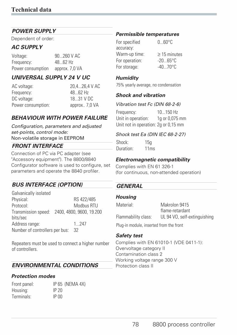
POWER SUPPLY
Dependent of order:
AC SUPPLY
Voltage: 90...260 V AC
Frequency: 48...62 Hz
Power consumption approx. 7,0 VA
UNIVERSAL SUPPLY 24 V UC
AC voltage: 20,4...26,4 V AC
Frequency: 48...62 Hz
DC voltage: 18...31 V DC
Power consumption: approx.. 7,0 VA
BEHAVIOUR WITH POWER FAILURE
Configuration, parameters and adjusted
set-points, control mode:
Non-volatile storage in EEPROM
FRONT INTERFACE
Connection of PC via PC adapter (see
"Accessory equipment"). The 8800/8840
Configurator software is used to configure, set
parameters and operate the 8840 profiler.
BUS INTERFACE (OPTION)
Galvanically isolated
Physical: RS 422/485
Protocol: Modbus RTU
Transmission speed: 2400, 4800, 9600, 19.200bits/sec
Address range: 1...247
Number of controllers per bus: 32
Repeaters must be used to connect a higher numberof controllers.
ENVIRONMENTAL CONDITIONS
Protection modes
Front panel: IP 65 (NEMA 4X)
Housing: IP 20
Terminals: IP 00
Permissible temperatures
For specifiedaccuracy:
0...60°C
Warm-up time: ≥ 15 minutes
For operation: -20...65°C
For storage: -40...70°C
Humidity
75% yearly average, no condensation
Shock and vibration
Vibration test Fc (DIN 68-2-6)
Frequency: 10...150 Hz
Unit in operation: 1g or 0,075 mm
Unit not in operation: 2g or 0,15 mm
Shock test Ea (DIN IEC 68-2-27)
Shock: 15g
Duration: 11ms
Electromagnetic compatibility
Complies with EN 61 326-1
(for continuous, non-attended operation)
GENERAL
Housing
Material: Makrolon 9415flame-retardant
Flammability class: UL 94 VO, self-extinguishing
Plug-in module, inserted from the front
Safety test
Complies with EN 61010-1 (VDE 0411-1):
Overvoltage category II
Contamination class 2
Working voltage range 300 V
Protection class II
Technical data
78 8800 process controller
Certifications
UL-approval
Electrical connections
w flat-pin terminals 1 x 6,3mm or 2 x 2,8mm toDIN 46 244 or
w screw terminals for 0,5 to 2,5mm²
Mounting
Panel mounting with two fixing clamps at
top/bottom or right/left,
High-density mounting possible
Mounting position: uncritical
Weight: 0,27kg
Accessories delivered with the unit
Operating manual
Fixing clamps
Technical data
8800 process controller 79
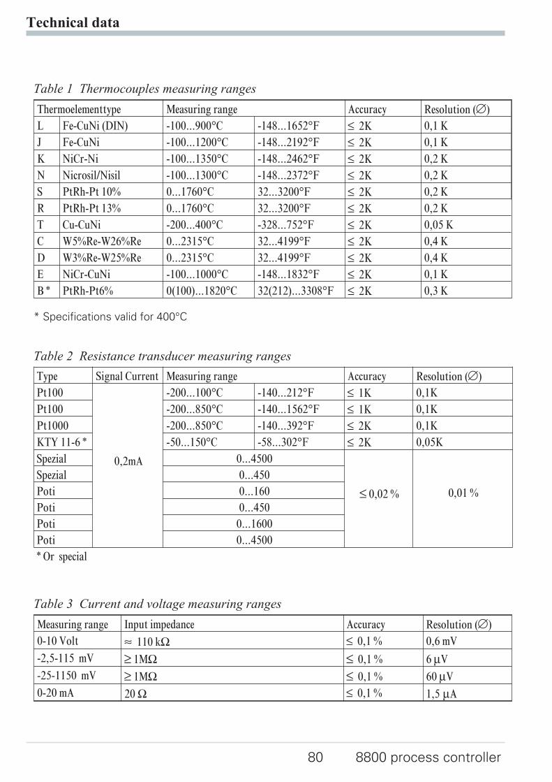
Technical data
80 8800 process controller
Thermoelementtype Measuring range Accuracy Resolution (Ô)
L Fe-CuNi (DIN) -100...900°C -148...1652°F ß 2K 0,1 K
J Fe-CuNi -100...1200°C -148...2192°F ß 2K 0,1 K
K NiCr-Ni -100...1350°C -148...2462°F ß 2K 0,2 K
N Nicrosil/Nisil -100...1300°C -148...2372°F ß 2K 0,2 K
S PtRh-Pt 10% 0...1760°C 32...3200°F ß 2K 0,2 K
R PtRh-Pt 13% 0...1760°C 32...3200°F ß 2K 0,2 K
T Cu-CuNi -200...400°C -328...752°F ß 2K 0,05 K
C W5%Re-W26%Re 0...2315°C 32...4199°F ß 2K 0,4 K
D W3%Re-W25%Re 0...2315°C 32...4199°F ß 2K 0,4 K
E NiCr-CuNi -100...1000°C -148...1832°F ß 2K 0,1 K
B * PtRh-Pt6% 0(100)...1820°C 32(212)...3308°F ß 2K 0,3 K
* Specifications valid for 400°C
Table 1 Thermocouples measuring ranges
Type Signal Current Measuring range Accuracy Resolution (Ô)
Pt100
0,2mA
-200...100°C -140...212°F ß 1K 0,1K
Pt100 -200...850°C -140...1562°F ß 1K 0,1K
Pt1000 -200...850°C -140...392°F ß 2K 0,1K
KTY 11-6 * -50...150°C -58...302°F ß 2K 0,05K
Spezial 0...4500
ß 0,02 % 0,01 %
Spezial 0...450
Poti 0...160
Poti 0...450
Poti 0...1600
Poti 0...4500
* Or special
Table 2 Resistance transducer measuring ranges
Measuring range Input impedance Accuracy Resolution (Ô)
0-10 Volt ~ 110 kΩ ß 0,1 % 0,6 mV
-2,5-115 mV ? 1MΩ ß 0,1 % 6 µV
-25-1150 mV ? 1MΩ ß 0,1 % 60 µV
0-20 mA 20 Ω ß 0,1 % 1,5 µA
Table 3 Current and voltage measuring ranges
11 Safety hints
This unit was built and tested in compliance with VDE 0411-1 / EN 61010-1 andwas delivered in safe condition.The unit complies with European guideline 89/336/EWG (EMC) and is providedwith CE marking.The unit was tested before delivery and has passed the tests required by the testschedule. To maintain this condition and to ensure safe operation, the user mustfollow the hints and warnings given in this operating manual.The unit is intended exclusively for use as a measurement and control instrumentin technical installations.
a WarningIf the unit is damaged to an extent that safe operation seems impossible, the unitmust not be taken into operation.
ELECTRICAL CONNECTIONSThe electrical wiring must conform to local standards (e.g. VDE 0100). The inputmeasurement and control leads must be kept separate from signal and powersupply leads.In the installation of the controller a switch or a circuit-breaker must be used andsignified. The switch or circuit-breaker must be installed near by the controllerand the user must have easy access to the controller.
COMMISSIONINGBefore instrument switch-on, check that the following information is taken intoaccount:
w Ensure that the supply voltage corresponds to the specifications on the typelabel.
w All covers required for contact protection must be fitted.
w If the controller is connected with other units in the same signal loop, checkthat the equipment in the output circuit is not affected before switch-on. Ifnecessary, suitable protective measures must be taken.
w The unit may be operated only in installed condition.
w Before and during operation, the temperature restrictions specified forcontroller operation must be met.
SHUT-DOWNFor taking the unit out of operation, disconnect it from all voltage sources andprotect it against accidental operation.If the controller is connected with other equipment in the same signal loop, checkthat other equipment in the output circuit is not affected before switch-off. Ifnecessary, suitable protective measures must be taken.
Safety hints
8800 process controller 81
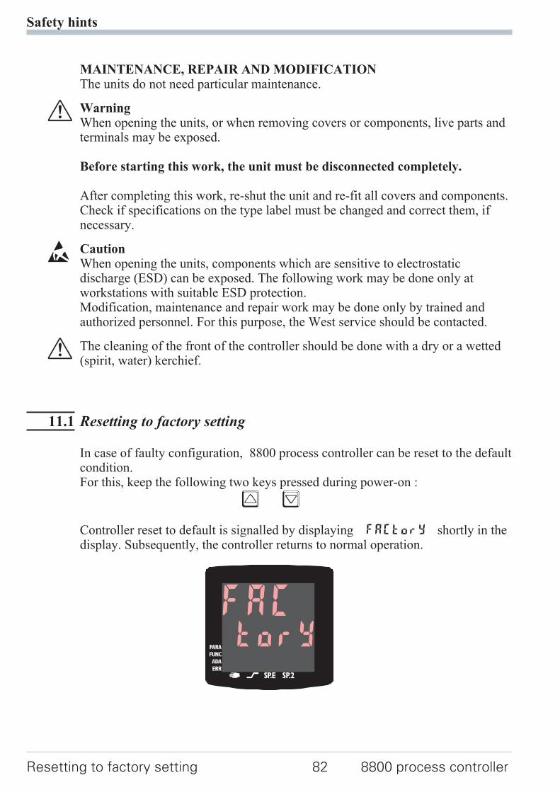
MAINTENANCE, REPAIR AND MODIFICATIONThe units do not need particular maintenance.
a WarningWhen opening the units, or when removing covers or components, live parts andterminals may be exposed.
Before starting this work, the unit must be disconnected completely.
After completing this work, re-shut the unit and re-fit all covers and components.Check if specifications on the type label must be changed and correct them, ifnecessary.
l CautionWhen opening the units, components which are sensitive to electrostaticdischarge (ESD) can be exposed. The following work may be done only atworkstations with suitable ESD protection.Modification, maintenance and repair work may be done only by trained andauthorized personnel. For this purpose, the West service should be contacted.
a The cleaning of the front of the controller should be done with a dry or a wetted(spirit, water) kerchief.
11.1 Resetting to factory setting
In case of faulty configuration, 8800 process controller can be reset to the defaultcondition.For this, keep the following two keys pressed during power-on :
È Ì
Controller reset to default is signalled by displaying FACTory shortly in thedisplay. Subsequently, the controller returns to normal operation.
Safety hints
Resetting to factory setting 82 8800 process controller
torYFAC

12 Notes
Notes
8800 process controller 83
Notes
84 8800 process controller

Notes
8800 process controller 85
Index
0-9
2-point correction. . . . . . . . . . . . 67
A
Alarm handling . . . . . . . . . . 28 - 29
B
Bargraph . . . . . . . . . . . . . . . . 12Bus interface
Technical Data. . . . . . . . . . 81
C
Calibration level (CAL) . . . . . . 67 - 69Certifications . . . . . . . . . . . . . . 82Configuration examples
2-point controller . . . . . . . . 553-point controller . . . . . . . . 563-point stepping controller . . . 57Continuous controller . . . . . . 58D - Y -Off controller. . . . . . . 59Measured value output . . . . . 60Signaller . . . . . . . . . . . . . 54
Configuration levelConfiguration parameters. . 32 - 49Parameter survey . . . . . . . . 31
Connecting diagram . . . . . . . . . . . 7Connecting examples
di2/3, 2-wire transmitter supply . 9INP2 current transformer . . . . . 8OUT1/2 heating/cooling . . . . . 8OUT3 as logic output . . . . . . 11OUT3 transmitter supply . . . . 10RS485 interface . . . . . . . . . 10
Control inputs di1, di2, di3Technical data . . . . . . . . . . 78
Cooling functionsConstant period . . . . . . . . . 53Standard . . . . . . . . . . . . . 51Water cooling non-linear . . . . 52
Current signal measuring range . . . . 78
D
DAC . . . . . . . . . . . . . . . . 70 - 71
Digital inputs di1, di2, di3Configuration . . . . . . . . . . 44Technical data . . . . . . . . . . 78
E
Environmental conditions . . . . . . . 81Equipment . . . . . . . . . . . . . . . 77Error list . . . . . . . . . . . . . . . . 15
F
Front view . . . . . . . . . . . . . . . 12
I
Input INP1Configuration . . . . . . . . . . 33Parameters . . . . . . . . . . . . 64Technical data . . . . . . . . . . 78
Input INP2Configuration . . . . . . . . . . 35Parameters . . . . . . . . . . . . 64Technical data . . . . . . . . . . 78
Input INP3Configuration . . . . . . . . . . 35Parameters . . . . . . . . . . . . 65Technical data . . . . . . . . . . 78
Input scaling . . . . . . . . . . . . . . 66
L
LEDAda - LED . . . . . . . . . . . . 12Err - LED . . . . . . . . . . . . 12func - LED. . . . . . . . . . . . 12
ì - LED. . . . . . . . . . . . . 12LED colours . . . . . . . . . . . 12
ò - LED. . . . . . . . . . . . . 12para - LED . . . . . . . . . . . . 12SP.2 - LED. . . . . . . . . . . . 12SP.E - LED . . . . . . . . . . . 12
Linearisierung . . . . . . . . . . . . . 74
M
Mainenance manager . . . . . . . 15 - 17Manual tuning . . . . . . . . . . . . . 26Modbus master . . . . . . . . . . . . . 75Mounting. . . . . . . . . . . . . . . . . 6
N
Notes. . . . . . . . . . . . . . . . 86 - 87
8800 process controller 86
O
O2-Messung . . . . . . . . . . . . . . 72Offset correction . . . . . . . . . . . . 67Optimierung am Sollwert . . . . . . . 20Output OUT1
Configuration . . . . . . . . . . 39Technical data . . . . . . . . . . 79
Output OUT2Configuration . . . . . . . . . . 40Technical data . . . . . . . . . . 79
Output OUT3Configuration . . . . . . . . . . 41Technical data . . . . . . . . . . 79
Output OUT4Configuration . . . . . . . . . . 42Technical data . . . . . . . . . . 79
Output OUT5Configuration . . . . . . . . . . 44Technical data . . . . . . . . . . 80
Output OUT6Configuration . . . . . . . . . . 44Technical data . . . . . . . . . . 80
P
Parameter setting levelParameter survey . . . . . . . . 62Parameters . . . . . . . . . 63 - 65
Parameter Sollwertgradient . . . . . . 64
R
Resetting to factory setting . . . . . . . 85Resistance thermometer measuring range. . . . . . . . . . . . . . . . . . . . . 78
S
Safety hints . . . . . . . . . . . . 84 - 85Safety switch. . . . . . . . . . . . . . . 6Safety test. . . . . . . . . . . . . . . . 81Sauerstoffmessung . . . . . . . . . . . 72Self-tuning
Cancelation . . . . . . . . . . . 23Cancelation causes. . . . . . . . 24
Set-point processing . . . . . . . . . . 50
T
Thermocouple measuring range . . . . 78
V
Versions . . . . . . . . . . . . . . . . 77Voltage signal measuring range . . . . 78
8800 process controller 87

Subject to alterations without noticeWest InstrumentsThe Hyde Business ParkBrightonBN2 4JUUKPrinted in Germany 9499-040-70611 (08/2003)
A6
Recommended