Principles of Bioelectronics Design Lecture 1
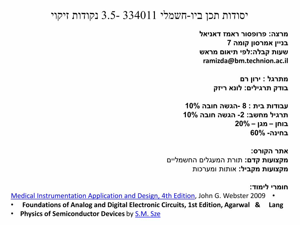
נקודות זיקוי334011-35חשמלי -יסודות תכן ביו
פרופסור ראמז דאניאל מרצה
7אמרסון קומה בניין
לפי תיאום מראשקבלהשעות
ramizdabmtechnionacil
ירון רם מתרגל
לונא ריזק בודק תרגילים
10הגשה חובה -8 עבודות בית
10הגשה חובה -2 תרגיל מחשב
20ndashמגן ndashבוחן
60-בחינה
אתר הקורס
תורת המעגלים החשמליים מקצועות קדם
ומערכותאותות מקצועות מקביל
חומרי לימודbullMedical Instrumentation Application and Design 4th Edition John G Webster 2009
bull Foundations of Analog and Digital Electronic Circuits 1st Edition Agarwal amp Langbull Physics of Semiconductor Devices by SM Sze
נקודות זיקוי334011-35חשמלי -יסודות תכן ביו
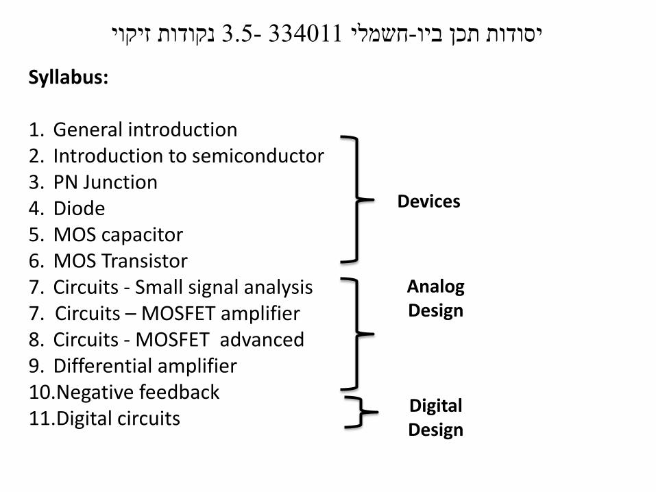
Syllabus
1 General introduction2 Introduction to semiconductor3 PN Junction 4 Diode5 MOS capacitor6 MOS Transistor7 Circuits - Small signal analysis 7 Circuits ndash MOSFET amplifier8 Circuits - MOSFET advanced 9 Differential amplifier10Negative feedback11Digital circuits
Devices
Analog Design
Digital Design
Why should we study electronic devices and circuits
Electrocardiogram potential (EKG)
Electroencephalography(EEG)
imaging capsule Glucose biosensor
Ultrasound
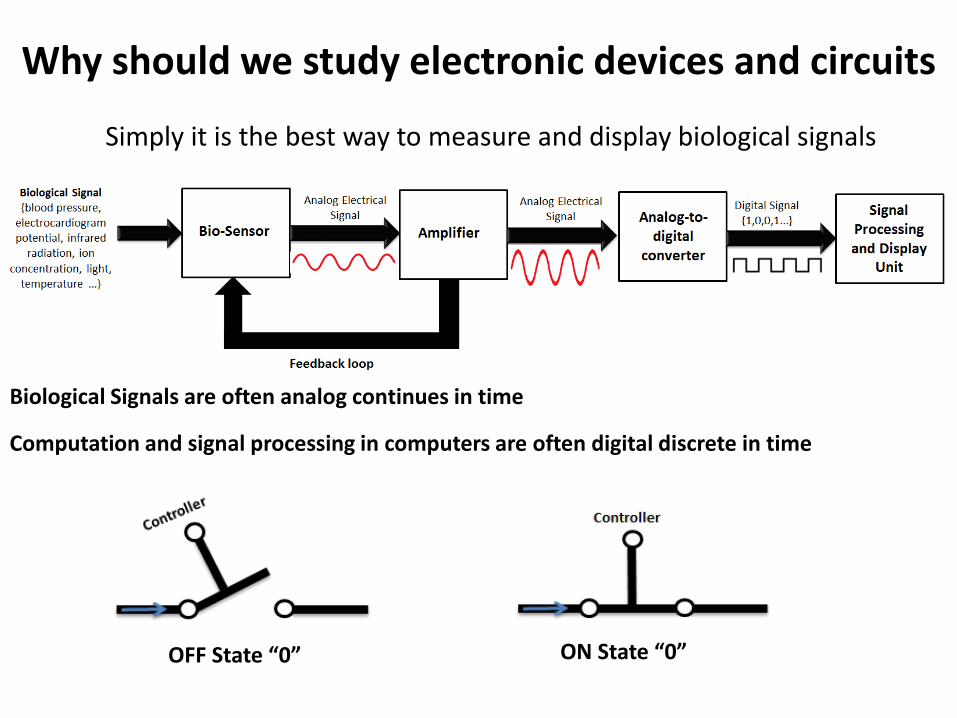
Why should we study electronic devices and circuits
Simply it is the best way to measure and display biological signals
Biological Signals are often analog continues in time
Computation and signal processing in computers are often digital discrete in time
OFF State ldquo0rdquo ON State ldquo0rdquo
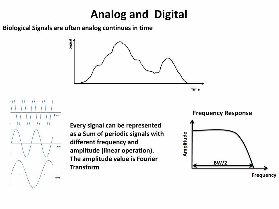
Analog and DigitalBiological Signals are often analog continues in time
Every signal can be represented as a Sum of periodic signals with different frequency and amplitude (linear operation) The amplitude value is Fourier Transform
Frequency Response
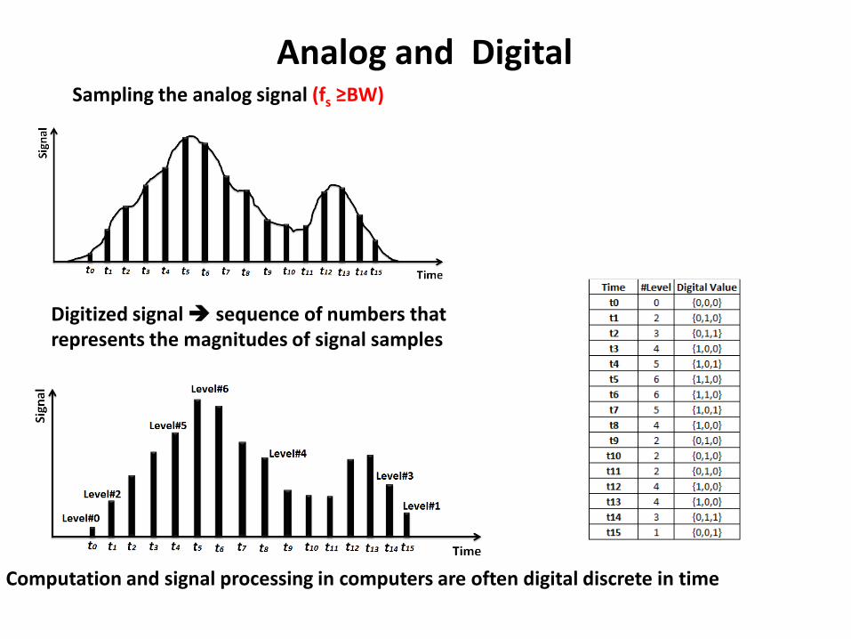
Analog and DigitalSampling the analog signal (fs geBW)
Digitized signal sequence of numbers that represents the magnitudes of signal samples
Computation and signal processing in computers are often digital discrete in time
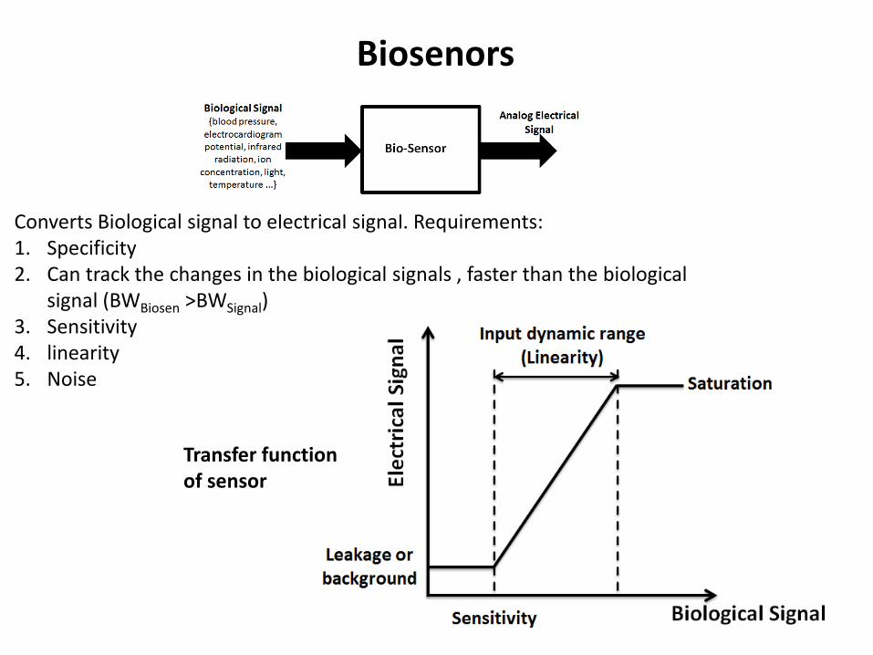
Converts Biological signal to electrical signal Requirements1 Specificity 2 Can track the changes in the biological signals faster than the biological
signal (BWBiosen gtBWSignal)3 Sensitivity4 linearity5 Noise
Biosenors
Transfer function of sensor
Linearization - Small Signal Analysis
Biosenors
119881 = 119891 119909
∆119907 =119889119891
119889119909119883119863
∙ ∆119883
119881 = 11988101198901199091198830
∆119881 =1
11988301198810119890
1198831198631198830 ∙ ∆119883
For example
119878119897119900119901119890 =∆119881
∆119883=
119881119863
1198830
First Order Biosensor
R and C are patristic
Biosenors
119868119861 = 119868119877 + 119868119862
119868119861 = 119891 119909
119868119877 =119881
119877 119868119862 = 119862
119889119881
119889119905
119862119889119881
119889119905+119881
119877= 119891 119909
119889119881
119889119905=
119891(119909)
119862minus
119881
119877119862
120591 = 119877119862
For constant IB
119881 119905 = 119868119861 ∙ 119877(1 minus 119890minus119905
120591)
119881 119905 = 120591 = 119868119861 ∙ 119877 1 minus 119890minus1 = 063119868119861 ∙ 119877
First Order Biosensor Frequency response
Biosenors
For constant IB
119889119881
119889119905=
119868119861119862minus119881
120591
119895120596119907 =119894119861119862minus119907
120591
119907 119895120596120591 + 1 = 119877 ∙ 119894119861
119907(120596) =119877 ∙ 119894119861(120596)
(119895120596120591 + 1)
120596119888 = 1120591
Fourier transform
119907(120596 = 0) = 119877 ∙ 119868119861
119907(120596 rarr infin) = 0
119907(120596) =119877 ∙ 119868119861
120596 1205961198882 + 1
119907(120596 = 120596119888) =119877 ∙ 119868119861
2
First Order Biosensor Frequency response
Biosenors
119907(120596) =119877 ∙ 119868119861
120596 1205961198882 + 1
120596119888 = 1119877119862
119907(120596 = 0) = 119877 ∙ 119868119861
119907(120596 rarr infin) = 0
Low pass filter every input signal with frequency higher ωC
will be cut-off
119907(120596 = 120596119888) =119877 ∙ 119868119861
2
log 1 2 asymp minus015
Low pass filter
Biosenors
ωb gt ωc V=0
sin 120596119887119905
Fourier transform
120575(120596 minus 120596119887)
ωb lt ωc V=Biological Signal
Therefore it is important to design the biosensor physical parameters to set the value of RC (eg dimensions )
119907(120596) =119877 ∙ 119894119861(120596)
(119895120596120591 + 1)
119907 120596 = 119894119861(120596) ∙ 119867119871119875119865(120596)
First Order Biosensor Frequency response
Biosenors
We can arrive to the same results by KCL and KVL
The impedance of R does not depend on the frequency (ZR=R)The impedance of C depends on the frequency (ZC=1jωC)
119881 = 119868119861 ∙ (119885119877||119885119862)
119881 = 119868119861119885119877 ∙ 119885119862119885119877 + 119885119862
119881 = 119868119861
119877 ∙1
119895120596119862
119877 +1
119895120596119862
119881 = 119868119861
119877 ∙1
119895120596119862119895120596119862119877 + 1
119895120596119862
119881 = 119868119861119877
119895120596119877119862 + 1
119881 = 119868119861119877
(120596119877119862)2+1
Biosensor converts one type of energy to electrical energyPhotodiode is pn junction that converts light to electrical energy
Biosenors -Photodiode
119862119889119881
119889119905+119881
119877= 119868119871119894119892ℎ119905 minus 119868119863119894119900119889119890
119868119863119894119900119889119890 = 119868119889119886119903119896(119890 119902119881 119870119879 minus 1)
Low pass filter
Light increases the
dark current
119877 =119889119881
119889119868=
119870119879
119902 ∙ 119868
C is the junction capacitance
Biosensor converts one type of energy to electrical energy
Piezoelectricity convert mechanical energy to electrical energyMeasure pressure and ultrasound waves
Biosenors - Piezoelectricity
It is reversbile an applied mechanical stress will generate a voltage and an applied voltage will change the shape of the solid by a small amount (up to a 4 change in volume)
Convert deflectiondisplacement to charge generator
Kxq K is a constant depends on the material
X is a deflection
R Sensor leakage resistance
C Sensor capacitance
Piezoelectric crystal (quartz)
x
AC r0
Biosenors - Piezoelectricity
Changes in x cause to change in the charge and producing a current
Convert charge generator to current generator
119868119861 =119889119902
119889119905= 119870
119889119909
119889119905
119862119889119881
119889119905+119881
119877= 119870
119889119909
119889119905
119889119881
119889119905= 119870119878
119889119909
119889119905minus119881
120591
Ks = KC sensitivity Vm
= RC time constant
Fourier transform
119895120596119907 = 119870119878 ∙ 119895120596119909(120596) minus119907
120591
119907(120596) =119870119878119895120596120591
1 + 119895120596120591∙ 119909(120596)
Biosenors - Piezoelectricity
Ks = KC sensitivity Vm
= RC time constant
119907(120596) =119870119878 ∙ 120596 120596119888
120596 1205961198882 + 1
∙ 119909(120596)
ωb lt ωc V=0
ωb gt ωc V ~ x
High Pass filter (HPF)
Electrochemical Biosenors
Electrochemistry interfacing electrode with electrolyte Oxidation Ions that lose their electronsReduction Ions that gain new electrons
Convert biochemical reactions to electrical signal
Electrochemical Biosenors
Equivalent electrical circuit of electrochemical cells
Rct Charge transfer resistance due to transfer of electrons from ions to electrodeCdl Double layer capacitor ndashaccumulation of charge in the interface between the electrolyte and electrodeRS series resistance ndash electrolyte solution resistance
119885119890119902 = 119877119904 +119877119888119905
1 + 119895 ∙ 120596 ∙ 119877119888119905 ∙ 119862119889119897
LPF
Amplifier
An input signals (currentvoltage) is amplified to a larger output signals (currentvoltage)
Features1 Linearity (wide linear range)2 High Gain3 Vin=0 Vout=04 High signal to noise ratio5 Stability at time (One dominant half time)6 Stable gain (not depend on circuit parameters VDD temperature hellip)
Amplifier
Amplifier
bull Voltage amplifier
119907119900119906119905 = 119860119907 ∙ 119907119894119899
Vin ndashinputVout ndashoutputAv ndash voltage gain [db]Ri is input resistanceRo output resistanceRS source resistanceRL Load Resistance
119907119894119899 = 119907119904 ∙119877119894
119877119894 + 119877119878 119907119900119906119905 = 119860119907119907119894119899 ∙119877119871
119877119871+119877119874
119907119900119906119905 = 119860119907119907119904 ∙119877119894
119877119894+119877119878∙
119877119871
119877119871+119877119874
119860119907119890119891119891 =119907119900119906119905
119907119904= 119860119907 ∙
119877119894
119877119894+119877119878∙
119877119871
119877119871+119877119874
20 log 119860119907 [119889119861] decibels
Amplifier
Differential amplifier
Reject common noise
∆119881119894119899 = 1198811198941198991 minus 1198811198941198992 = 1198811198941198991 + ∆ minus 1198811198941198992 minus ∆
∆119881119894119899 = 1198811198941198991 minus 1198811198941198992
)119881119900119906119905 = 119860 ∙ (1198811198941198991 minus 1198811198941198992
Negative feedbackNegative feedback loop when the output of the system feed it back to control and reduce his activity
)119881119900119906119905 = 119860 ∙ (1198811198941198991 minus 1198811198941198992
1198811198941198992 = 120573 ∙ 119881119900119906119905
Open loop equation
Negative feedback loop equation
rArr 119881119900119906119905= 119860 ∙ 1198811198941198991 minus 120573 ∙ 119881119900119906119905
119933119952119958119957 = 119933119946119951120783 ∙119912
120783 + 120631 ∙ 119912Blackrsquos Formula
β∙Agtgt1 Vout=Vin1βNegative feedback can increase the stability
Analog-to-digital converts
Noise accumulated in analog circuits
Solution Digital circuit
noise hampers our ability to distinguish between small differences in value mdasheg between 31V and 32V
Digital circuits1 Device of two states (OFFON) or (01)
119881119900119906119905 = 119881119874119873 119881119894119899gt 119881119905ℎ119881119900119891119891 119881119894119899 lt 119881119905ℎ
2 Computation arises from logic functions (Boolean algebra) using basic logic gates
נקודות זיקוי334011-35חשמלי -יסודות תכן ביו
פרופסור ראמז דאניאל מרצה
7אמרסון קומה בניין
לפי תיאום מראשקבלהשעות
ramizdabmtechnionacil
ירון רם מתרגל
לונא ריזק בודק תרגילים
10הגשה חובה -8 עבודות בית
10הגשה חובה -2 תרגיל מחשב
20ndashמגן ndashבוחן
60-בחינה
אתר הקורס
תורת המעגלים החשמליים מקצועות קדם
ומערכותאותות מקצועות מקביל
חומרי לימודbullMedical Instrumentation Application and Design 4th Edition John G Webster 2009
bull Foundations of Analog and Digital Electronic Circuits 1st Edition Agarwal amp Langbull Physics of Semiconductor Devices by SM Sze
נקודות זיקוי334011-35חשמלי -יסודות תכן ביו
Syllabus
1 General introduction2 Introduction to semiconductor3 PN Junction 4 Diode5 MOS capacitor6 MOS Transistor7 Circuits - Small signal analysis 7 Circuits ndash MOSFET amplifier8 Circuits - MOSFET advanced 9 Differential amplifier10Negative feedback11Digital circuits
Devices
Analog Design
Digital Design
Why should we study electronic devices and circuits
Electrocardiogram potential (EKG)
Electroencephalography(EEG)
imaging capsule Glucose biosensor
Ultrasound
Why should we study electronic devices and circuits
Simply it is the best way to measure and display biological signals
Biological Signals are often analog continues in time
Computation and signal processing in computers are often digital discrete in time
OFF State ldquo0rdquo ON State ldquo0rdquo
Analog and DigitalBiological Signals are often analog continues in time
Every signal can be represented as a Sum of periodic signals with different frequency and amplitude (linear operation) The amplitude value is Fourier Transform
Frequency Response
Analog and DigitalSampling the analog signal (fs geBW)
Digitized signal sequence of numbers that represents the magnitudes of signal samples
Computation and signal processing in computers are often digital discrete in time
Converts Biological signal to electrical signal Requirements1 Specificity 2 Can track the changes in the biological signals faster than the biological
signal (BWBiosen gtBWSignal)3 Sensitivity4 linearity5 Noise
Biosenors
Transfer function of sensor
Linearization - Small Signal Analysis
Biosenors
119881 = 119891 119909
∆119907 =119889119891
119889119909119883119863
∙ ∆119883
119881 = 11988101198901199091198830
∆119881 =1
11988301198810119890
1198831198631198830 ∙ ∆119883
For example
119878119897119900119901119890 =∆119881
∆119883=
119881119863
1198830
First Order Biosensor
R and C are patristic
Biosenors
119868119861 = 119868119877 + 119868119862
119868119861 = 119891 119909
119868119877 =119881
119877 119868119862 = 119862
119889119881
119889119905
119862119889119881
119889119905+119881
119877= 119891 119909
119889119881
119889119905=
119891(119909)
119862minus
119881
119877119862
120591 = 119877119862
For constant IB
119881 119905 = 119868119861 ∙ 119877(1 minus 119890minus119905
120591)
119881 119905 = 120591 = 119868119861 ∙ 119877 1 minus 119890minus1 = 063119868119861 ∙ 119877
First Order Biosensor Frequency response
Biosenors
For constant IB
119889119881
119889119905=
119868119861119862minus119881
120591
119895120596119907 =119894119861119862minus119907
120591
119907 119895120596120591 + 1 = 119877 ∙ 119894119861
119907(120596) =119877 ∙ 119894119861(120596)
(119895120596120591 + 1)
120596119888 = 1120591
Fourier transform
119907(120596 = 0) = 119877 ∙ 119868119861
119907(120596 rarr infin) = 0
119907(120596) =119877 ∙ 119868119861
120596 1205961198882 + 1
119907(120596 = 120596119888) =119877 ∙ 119868119861
2
First Order Biosensor Frequency response
Biosenors
119907(120596) =119877 ∙ 119868119861
120596 1205961198882 + 1
120596119888 = 1119877119862
119907(120596 = 0) = 119877 ∙ 119868119861
119907(120596 rarr infin) = 0
Low pass filter every input signal with frequency higher ωC
will be cut-off
119907(120596 = 120596119888) =119877 ∙ 119868119861
2
log 1 2 asymp minus015
Low pass filter
Biosenors
ωb gt ωc V=0
sin 120596119887119905
Fourier transform
120575(120596 minus 120596119887)
ωb lt ωc V=Biological Signal
Therefore it is important to design the biosensor physical parameters to set the value of RC (eg dimensions )
119907(120596) =119877 ∙ 119894119861(120596)
(119895120596120591 + 1)
119907 120596 = 119894119861(120596) ∙ 119867119871119875119865(120596)
First Order Biosensor Frequency response
Biosenors
We can arrive to the same results by KCL and KVL
The impedance of R does not depend on the frequency (ZR=R)The impedance of C depends on the frequency (ZC=1jωC)
119881 = 119868119861 ∙ (119885119877||119885119862)
119881 = 119868119861119885119877 ∙ 119885119862119885119877 + 119885119862
119881 = 119868119861
119877 ∙1
119895120596119862
119877 +1
119895120596119862
119881 = 119868119861
119877 ∙1
119895120596119862119895120596119862119877 + 1
119895120596119862
119881 = 119868119861119877
119895120596119877119862 + 1
119881 = 119868119861119877
(120596119877119862)2+1
Biosensor converts one type of energy to electrical energyPhotodiode is pn junction that converts light to electrical energy
Biosenors -Photodiode
119862119889119881
119889119905+119881
119877= 119868119871119894119892ℎ119905 minus 119868119863119894119900119889119890
119868119863119894119900119889119890 = 119868119889119886119903119896(119890 119902119881 119870119879 minus 1)
Low pass filter
Light increases the
dark current
119877 =119889119881
119889119868=
119870119879
119902 ∙ 119868
C is the junction capacitance
Biosensor converts one type of energy to electrical energy
Piezoelectricity convert mechanical energy to electrical energyMeasure pressure and ultrasound waves
Biosenors - Piezoelectricity
It is reversbile an applied mechanical stress will generate a voltage and an applied voltage will change the shape of the solid by a small amount (up to a 4 change in volume)
Convert deflectiondisplacement to charge generator
Kxq K is a constant depends on the material
X is a deflection
R Sensor leakage resistance
C Sensor capacitance
Piezoelectric crystal (quartz)
x
AC r0
Biosenors - Piezoelectricity
Changes in x cause to change in the charge and producing a current
Convert charge generator to current generator
119868119861 =119889119902
119889119905= 119870
119889119909
119889119905
119862119889119881
119889119905+119881
119877= 119870
119889119909
119889119905
119889119881
119889119905= 119870119878
119889119909
119889119905minus119881
120591
Ks = KC sensitivity Vm
= RC time constant
Fourier transform
119895120596119907 = 119870119878 ∙ 119895120596119909(120596) minus119907
120591
119907(120596) =119870119878119895120596120591
1 + 119895120596120591∙ 119909(120596)
Biosenors - Piezoelectricity
Ks = KC sensitivity Vm
= RC time constant
119907(120596) =119870119878 ∙ 120596 120596119888
120596 1205961198882 + 1
∙ 119909(120596)
ωb lt ωc V=0
ωb gt ωc V ~ x
High Pass filter (HPF)
Electrochemical Biosenors
Electrochemistry interfacing electrode with electrolyte Oxidation Ions that lose their electronsReduction Ions that gain new electrons
Convert biochemical reactions to electrical signal
Electrochemical Biosenors
Equivalent electrical circuit of electrochemical cells
Rct Charge transfer resistance due to transfer of electrons from ions to electrodeCdl Double layer capacitor ndashaccumulation of charge in the interface between the electrolyte and electrodeRS series resistance ndash electrolyte solution resistance
119885119890119902 = 119877119904 +119877119888119905
1 + 119895 ∙ 120596 ∙ 119877119888119905 ∙ 119862119889119897
LPF
Amplifier
An input signals (currentvoltage) is amplified to a larger output signals (currentvoltage)
Features1 Linearity (wide linear range)2 High Gain3 Vin=0 Vout=04 High signal to noise ratio5 Stability at time (One dominant half time)6 Stable gain (not depend on circuit parameters VDD temperature hellip)
Amplifier
Amplifier
bull Voltage amplifier
119907119900119906119905 = 119860119907 ∙ 119907119894119899
Vin ndashinputVout ndashoutputAv ndash voltage gain [db]Ri is input resistanceRo output resistanceRS source resistanceRL Load Resistance
119907119894119899 = 119907119904 ∙119877119894
119877119894 + 119877119878 119907119900119906119905 = 119860119907119907119894119899 ∙119877119871
119877119871+119877119874
119907119900119906119905 = 119860119907119907119904 ∙119877119894
119877119894+119877119878∙
119877119871
119877119871+119877119874
119860119907119890119891119891 =119907119900119906119905
119907119904= 119860119907 ∙
119877119894
119877119894+119877119878∙
119877119871
119877119871+119877119874
20 log 119860119907 [119889119861] decibels
Amplifier
Differential amplifier
Reject common noise
∆119881119894119899 = 1198811198941198991 minus 1198811198941198992 = 1198811198941198991 + ∆ minus 1198811198941198992 minus ∆
∆119881119894119899 = 1198811198941198991 minus 1198811198941198992
)119881119900119906119905 = 119860 ∙ (1198811198941198991 minus 1198811198941198992
Negative feedbackNegative feedback loop when the output of the system feed it back to control and reduce his activity
)119881119900119906119905 = 119860 ∙ (1198811198941198991 minus 1198811198941198992
1198811198941198992 = 120573 ∙ 119881119900119906119905
Open loop equation
Negative feedback loop equation
rArr 119881119900119906119905= 119860 ∙ 1198811198941198991 minus 120573 ∙ 119881119900119906119905
119933119952119958119957 = 119933119946119951120783 ∙119912
120783 + 120631 ∙ 119912Blackrsquos Formula
β∙Agtgt1 Vout=Vin1βNegative feedback can increase the stability
Analog-to-digital converts
Noise accumulated in analog circuits
Solution Digital circuit
noise hampers our ability to distinguish between small differences in value mdasheg between 31V and 32V
Digital circuits1 Device of two states (OFFON) or (01)
119881119900119906119905 = 119881119874119873 119881119894119899gt 119881119905ℎ119881119900119891119891 119881119894119899 lt 119881119905ℎ
2 Computation arises from logic functions (Boolean algebra) using basic logic gates
נקודות זיקוי334011-35חשמלי -יסודות תכן ביו
Syllabus
1 General introduction2 Introduction to semiconductor3 PN Junction 4 Diode5 MOS capacitor6 MOS Transistor7 Circuits - Small signal analysis 7 Circuits ndash MOSFET amplifier8 Circuits - MOSFET advanced 9 Differential amplifier10Negative feedback11Digital circuits
Devices
Analog Design
Digital Design
Why should we study electronic devices and circuits
Electrocardiogram potential (EKG)
Electroencephalography(EEG)
imaging capsule Glucose biosensor
Ultrasound
Why should we study electronic devices and circuits
Simply it is the best way to measure and display biological signals
Biological Signals are often analog continues in time
Computation and signal processing in computers are often digital discrete in time
OFF State ldquo0rdquo ON State ldquo0rdquo
Analog and DigitalBiological Signals are often analog continues in time
Every signal can be represented as a Sum of periodic signals with different frequency and amplitude (linear operation) The amplitude value is Fourier Transform
Frequency Response
Analog and DigitalSampling the analog signal (fs geBW)
Digitized signal sequence of numbers that represents the magnitudes of signal samples
Computation and signal processing in computers are often digital discrete in time
Converts Biological signal to electrical signal Requirements1 Specificity 2 Can track the changes in the biological signals faster than the biological
signal (BWBiosen gtBWSignal)3 Sensitivity4 linearity5 Noise
Biosenors
Transfer function of sensor
Linearization - Small Signal Analysis
Biosenors
119881 = 119891 119909
∆119907 =119889119891
119889119909119883119863
∙ ∆119883
119881 = 11988101198901199091198830
∆119881 =1
11988301198810119890
1198831198631198830 ∙ ∆119883
For example
119878119897119900119901119890 =∆119881
∆119883=
119881119863
1198830
First Order Biosensor
R and C are patristic
Biosenors
119868119861 = 119868119877 + 119868119862
119868119861 = 119891 119909
119868119877 =119881
119877 119868119862 = 119862
119889119881
119889119905
119862119889119881
119889119905+119881
119877= 119891 119909
119889119881
119889119905=
119891(119909)
119862minus
119881
119877119862
120591 = 119877119862
For constant IB
119881 119905 = 119868119861 ∙ 119877(1 minus 119890minus119905
120591)
119881 119905 = 120591 = 119868119861 ∙ 119877 1 minus 119890minus1 = 063119868119861 ∙ 119877
First Order Biosensor Frequency response
Biosenors
For constant IB
119889119881
119889119905=
119868119861119862minus119881
120591
119895120596119907 =119894119861119862minus119907
120591
119907 119895120596120591 + 1 = 119877 ∙ 119894119861
119907(120596) =119877 ∙ 119894119861(120596)
(119895120596120591 + 1)
120596119888 = 1120591
Fourier transform
119907(120596 = 0) = 119877 ∙ 119868119861
119907(120596 rarr infin) = 0
119907(120596) =119877 ∙ 119868119861
120596 1205961198882 + 1
119907(120596 = 120596119888) =119877 ∙ 119868119861
2
First Order Biosensor Frequency response
Biosenors
119907(120596) =119877 ∙ 119868119861
120596 1205961198882 + 1
120596119888 = 1119877119862
119907(120596 = 0) = 119877 ∙ 119868119861
119907(120596 rarr infin) = 0
Low pass filter every input signal with frequency higher ωC
will be cut-off
119907(120596 = 120596119888) =119877 ∙ 119868119861
2
log 1 2 asymp minus015
Low pass filter
Biosenors
ωb gt ωc V=0
sin 120596119887119905
Fourier transform
120575(120596 minus 120596119887)
ωb lt ωc V=Biological Signal
Therefore it is important to design the biosensor physical parameters to set the value of RC (eg dimensions )
119907(120596) =119877 ∙ 119894119861(120596)
(119895120596120591 + 1)
119907 120596 = 119894119861(120596) ∙ 119867119871119875119865(120596)
First Order Biosensor Frequency response
Biosenors
We can arrive to the same results by KCL and KVL
The impedance of R does not depend on the frequency (ZR=R)The impedance of C depends on the frequency (ZC=1jωC)
119881 = 119868119861 ∙ (119885119877||119885119862)
119881 = 119868119861119885119877 ∙ 119885119862119885119877 + 119885119862
119881 = 119868119861
119877 ∙1
119895120596119862
119877 +1
119895120596119862
119881 = 119868119861
119877 ∙1
119895120596119862119895120596119862119877 + 1
119895120596119862
119881 = 119868119861119877
119895120596119877119862 + 1
119881 = 119868119861119877
(120596119877119862)2+1
Biosensor converts one type of energy to electrical energyPhotodiode is pn junction that converts light to electrical energy
Biosenors -Photodiode
119862119889119881
119889119905+119881
119877= 119868119871119894119892ℎ119905 minus 119868119863119894119900119889119890
119868119863119894119900119889119890 = 119868119889119886119903119896(119890 119902119881 119870119879 minus 1)
Low pass filter
Light increases the
dark current
119877 =119889119881
119889119868=
119870119879
119902 ∙ 119868
C is the junction capacitance
Biosensor converts one type of energy to electrical energy
Piezoelectricity convert mechanical energy to electrical energyMeasure pressure and ultrasound waves
Biosenors - Piezoelectricity
It is reversbile an applied mechanical stress will generate a voltage and an applied voltage will change the shape of the solid by a small amount (up to a 4 change in volume)
Convert deflectiondisplacement to charge generator
Kxq K is a constant depends on the material
X is a deflection
R Sensor leakage resistance
C Sensor capacitance
Piezoelectric crystal (quartz)
x
AC r0
Biosenors - Piezoelectricity
Changes in x cause to change in the charge and producing a current
Convert charge generator to current generator
119868119861 =119889119902
119889119905= 119870
119889119909
119889119905
119862119889119881
119889119905+119881
119877= 119870
119889119909
119889119905
119889119881
119889119905= 119870119878
119889119909
119889119905minus119881
120591
Ks = KC sensitivity Vm
= RC time constant
Fourier transform
119895120596119907 = 119870119878 ∙ 119895120596119909(120596) minus119907
120591
119907(120596) =119870119878119895120596120591
1 + 119895120596120591∙ 119909(120596)
Biosenors - Piezoelectricity
Ks = KC sensitivity Vm
= RC time constant
119907(120596) =119870119878 ∙ 120596 120596119888
120596 1205961198882 + 1
∙ 119909(120596)
ωb lt ωc V=0
ωb gt ωc V ~ x
High Pass filter (HPF)
Electrochemical Biosenors
Electrochemistry interfacing electrode with electrolyte Oxidation Ions that lose their electronsReduction Ions that gain new electrons
Convert biochemical reactions to electrical signal
Electrochemical Biosenors
Equivalent electrical circuit of electrochemical cells
Rct Charge transfer resistance due to transfer of electrons from ions to electrodeCdl Double layer capacitor ndashaccumulation of charge in the interface between the electrolyte and electrodeRS series resistance ndash electrolyte solution resistance
119885119890119902 = 119877119904 +119877119888119905
1 + 119895 ∙ 120596 ∙ 119877119888119905 ∙ 119862119889119897
LPF
Amplifier
An input signals (currentvoltage) is amplified to a larger output signals (currentvoltage)
Features1 Linearity (wide linear range)2 High Gain3 Vin=0 Vout=04 High signal to noise ratio5 Stability at time (One dominant half time)6 Stable gain (not depend on circuit parameters VDD temperature hellip)
Amplifier
Amplifier
bull Voltage amplifier
119907119900119906119905 = 119860119907 ∙ 119907119894119899
Vin ndashinputVout ndashoutputAv ndash voltage gain [db]Ri is input resistanceRo output resistanceRS source resistanceRL Load Resistance
119907119894119899 = 119907119904 ∙119877119894
119877119894 + 119877119878 119907119900119906119905 = 119860119907119907119894119899 ∙119877119871
119877119871+119877119874
119907119900119906119905 = 119860119907119907119904 ∙119877119894
119877119894+119877119878∙
119877119871
119877119871+119877119874
119860119907119890119891119891 =119907119900119906119905
119907119904= 119860119907 ∙
119877119894
119877119894+119877119878∙
119877119871
119877119871+119877119874
20 log 119860119907 [119889119861] decibels
Amplifier
Differential amplifier
Reject common noise
∆119881119894119899 = 1198811198941198991 minus 1198811198941198992 = 1198811198941198991 + ∆ minus 1198811198941198992 minus ∆
∆119881119894119899 = 1198811198941198991 minus 1198811198941198992
)119881119900119906119905 = 119860 ∙ (1198811198941198991 minus 1198811198941198992
Negative feedbackNegative feedback loop when the output of the system feed it back to control and reduce his activity
)119881119900119906119905 = 119860 ∙ (1198811198941198991 minus 1198811198941198992
1198811198941198992 = 120573 ∙ 119881119900119906119905
Open loop equation
Negative feedback loop equation
rArr 119881119900119906119905= 119860 ∙ 1198811198941198991 minus 120573 ∙ 119881119900119906119905
119933119952119958119957 = 119933119946119951120783 ∙119912
120783 + 120631 ∙ 119912Blackrsquos Formula
β∙Agtgt1 Vout=Vin1βNegative feedback can increase the stability
Analog-to-digital converts
Noise accumulated in analog circuits
Solution Digital circuit
noise hampers our ability to distinguish between small differences in value mdasheg between 31V and 32V
Digital circuits1 Device of two states (OFFON) or (01)
119881119900119906119905 = 119881119874119873 119881119894119899gt 119881119905ℎ119881119900119891119891 119881119894119899 lt 119881119905ℎ
2 Computation arises from logic functions (Boolean algebra) using basic logic gates

Why should we study electronic devices and circuits
Electrocardiogram potential (EKG)
Electroencephalography(EEG)
imaging capsule Glucose biosensor
Ultrasound
Why should we study electronic devices and circuits
Simply it is the best way to measure and display biological signals
Biological Signals are often analog continues in time
Computation and signal processing in computers are often digital discrete in time
OFF State ldquo0rdquo ON State ldquo0rdquo
Analog and DigitalBiological Signals are often analog continues in time
Every signal can be represented as a Sum of periodic signals with different frequency and amplitude (linear operation) The amplitude value is Fourier Transform
Frequency Response
Analog and DigitalSampling the analog signal (fs geBW)
Digitized signal sequence of numbers that represents the magnitudes of signal samples
Computation and signal processing in computers are often digital discrete in time
Converts Biological signal to electrical signal Requirements1 Specificity 2 Can track the changes in the biological signals faster than the biological
signal (BWBiosen gtBWSignal)3 Sensitivity4 linearity5 Noise
Biosenors
Transfer function of sensor
Linearization - Small Signal Analysis
Biosenors
119881 = 119891 119909
∆119907 =119889119891
119889119909119883119863
∙ ∆119883
119881 = 11988101198901199091198830
∆119881 =1
11988301198810119890
1198831198631198830 ∙ ∆119883
For example
119878119897119900119901119890 =∆119881
∆119883=
119881119863
1198830
First Order Biosensor
R and C are patristic
Biosenors
119868119861 = 119868119877 + 119868119862
119868119861 = 119891 119909
119868119877 =119881
119877 119868119862 = 119862
119889119881
119889119905
119862119889119881
119889119905+119881
119877= 119891 119909
119889119881
119889119905=
119891(119909)
119862minus
119881
119877119862
120591 = 119877119862
For constant IB
119881 119905 = 119868119861 ∙ 119877(1 minus 119890minus119905
120591)
119881 119905 = 120591 = 119868119861 ∙ 119877 1 minus 119890minus1 = 063119868119861 ∙ 119877
First Order Biosensor Frequency response
Biosenors
For constant IB
119889119881
119889119905=
119868119861119862minus119881
120591
119895120596119907 =119894119861119862minus119907
120591
119907 119895120596120591 + 1 = 119877 ∙ 119894119861
119907(120596) =119877 ∙ 119894119861(120596)
(119895120596120591 + 1)
120596119888 = 1120591
Fourier transform
119907(120596 = 0) = 119877 ∙ 119868119861
119907(120596 rarr infin) = 0
119907(120596) =119877 ∙ 119868119861
120596 1205961198882 + 1
119907(120596 = 120596119888) =119877 ∙ 119868119861
2
First Order Biosensor Frequency response
Biosenors
119907(120596) =119877 ∙ 119868119861
120596 1205961198882 + 1
120596119888 = 1119877119862
119907(120596 = 0) = 119877 ∙ 119868119861
119907(120596 rarr infin) = 0
Low pass filter every input signal with frequency higher ωC
will be cut-off
119907(120596 = 120596119888) =119877 ∙ 119868119861
2
log 1 2 asymp minus015
Low pass filter
Biosenors
ωb gt ωc V=0
sin 120596119887119905
Fourier transform
120575(120596 minus 120596119887)
ωb lt ωc V=Biological Signal
Therefore it is important to design the biosensor physical parameters to set the value of RC (eg dimensions )
119907(120596) =119877 ∙ 119894119861(120596)
(119895120596120591 + 1)
119907 120596 = 119894119861(120596) ∙ 119867119871119875119865(120596)
First Order Biosensor Frequency response
Biosenors
We can arrive to the same results by KCL and KVL
The impedance of R does not depend on the frequency (ZR=R)The impedance of C depends on the frequency (ZC=1jωC)
119881 = 119868119861 ∙ (119885119877||119885119862)
119881 = 119868119861119885119877 ∙ 119885119862119885119877 + 119885119862
119881 = 119868119861
119877 ∙1
119895120596119862
119877 +1
119895120596119862
119881 = 119868119861
119877 ∙1
119895120596119862119895120596119862119877 + 1
119895120596119862
119881 = 119868119861119877
119895120596119877119862 + 1
119881 = 119868119861119877
(120596119877119862)2+1
Biosensor converts one type of energy to electrical energyPhotodiode is pn junction that converts light to electrical energy
Biosenors -Photodiode
119862119889119881
119889119905+119881
119877= 119868119871119894119892ℎ119905 minus 119868119863119894119900119889119890
119868119863119894119900119889119890 = 119868119889119886119903119896(119890 119902119881 119870119879 minus 1)
Low pass filter
Light increases the
dark current
119877 =119889119881
119889119868=
119870119879
119902 ∙ 119868
C is the junction capacitance
Biosensor converts one type of energy to electrical energy
Piezoelectricity convert mechanical energy to electrical energyMeasure pressure and ultrasound waves
Biosenors - Piezoelectricity
It is reversbile an applied mechanical stress will generate a voltage and an applied voltage will change the shape of the solid by a small amount (up to a 4 change in volume)
Convert deflectiondisplacement to charge generator
Kxq K is a constant depends on the material
X is a deflection
R Sensor leakage resistance
C Sensor capacitance
Piezoelectric crystal (quartz)
x
AC r0
Biosenors - Piezoelectricity
Changes in x cause to change in the charge and producing a current
Convert charge generator to current generator
119868119861 =119889119902
119889119905= 119870
119889119909
119889119905
119862119889119881
119889119905+119881
119877= 119870
119889119909
119889119905
119889119881
119889119905= 119870119878
119889119909
119889119905minus119881
120591
Ks = KC sensitivity Vm
= RC time constant
Fourier transform
119895120596119907 = 119870119878 ∙ 119895120596119909(120596) minus119907
120591
119907(120596) =119870119878119895120596120591
1 + 119895120596120591∙ 119909(120596)
Biosenors - Piezoelectricity
Ks = KC sensitivity Vm
= RC time constant
119907(120596) =119870119878 ∙ 120596 120596119888
120596 1205961198882 + 1
∙ 119909(120596)
ωb lt ωc V=0
ωb gt ωc V ~ x
High Pass filter (HPF)
Electrochemical Biosenors
Electrochemistry interfacing electrode with electrolyte Oxidation Ions that lose their electronsReduction Ions that gain new electrons
Convert biochemical reactions to electrical signal
Electrochemical Biosenors
Equivalent electrical circuit of electrochemical cells
Rct Charge transfer resistance due to transfer of electrons from ions to electrodeCdl Double layer capacitor ndashaccumulation of charge in the interface between the electrolyte and electrodeRS series resistance ndash electrolyte solution resistance
119885119890119902 = 119877119904 +119877119888119905
1 + 119895 ∙ 120596 ∙ 119877119888119905 ∙ 119862119889119897
LPF
Amplifier
An input signals (currentvoltage) is amplified to a larger output signals (currentvoltage)
Features1 Linearity (wide linear range)2 High Gain3 Vin=0 Vout=04 High signal to noise ratio5 Stability at time (One dominant half time)6 Stable gain (not depend on circuit parameters VDD temperature hellip)
Amplifier
Amplifier
bull Voltage amplifier
119907119900119906119905 = 119860119907 ∙ 119907119894119899
Vin ndashinputVout ndashoutputAv ndash voltage gain [db]Ri is input resistanceRo output resistanceRS source resistanceRL Load Resistance
119907119894119899 = 119907119904 ∙119877119894
119877119894 + 119877119878 119907119900119906119905 = 119860119907119907119894119899 ∙119877119871
119877119871+119877119874
119907119900119906119905 = 119860119907119907119904 ∙119877119894
119877119894+119877119878∙
119877119871
119877119871+119877119874
119860119907119890119891119891 =119907119900119906119905
119907119904= 119860119907 ∙
119877119894
119877119894+119877119878∙
119877119871
119877119871+119877119874
20 log 119860119907 [119889119861] decibels
Amplifier
Differential amplifier
Reject common noise
∆119881119894119899 = 1198811198941198991 minus 1198811198941198992 = 1198811198941198991 + ∆ minus 1198811198941198992 minus ∆
∆119881119894119899 = 1198811198941198991 minus 1198811198941198992
)119881119900119906119905 = 119860 ∙ (1198811198941198991 minus 1198811198941198992
Negative feedbackNegative feedback loop when the output of the system feed it back to control and reduce his activity
)119881119900119906119905 = 119860 ∙ (1198811198941198991 minus 1198811198941198992
1198811198941198992 = 120573 ∙ 119881119900119906119905
Open loop equation
Negative feedback loop equation
rArr 119881119900119906119905= 119860 ∙ 1198811198941198991 minus 120573 ∙ 119881119900119906119905
119933119952119958119957 = 119933119946119951120783 ∙119912
120783 + 120631 ∙ 119912Blackrsquos Formula
β∙Agtgt1 Vout=Vin1βNegative feedback can increase the stability
Analog-to-digital converts
Noise accumulated in analog circuits
Solution Digital circuit
noise hampers our ability to distinguish between small differences in value mdasheg between 31V and 32V
Digital circuits1 Device of two states (OFFON) or (01)
119881119900119906119905 = 119881119874119873 119881119894119899gt 119881119905ℎ119881119900119891119891 119881119894119899 lt 119881119905ℎ
2 Computation arises from logic functions (Boolean algebra) using basic logic gates
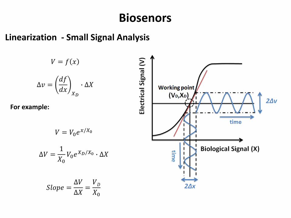
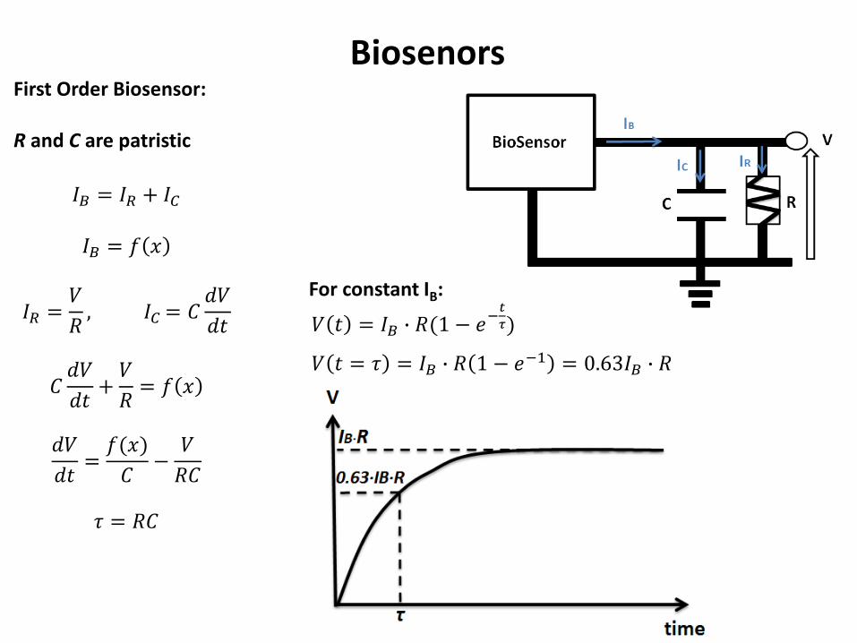
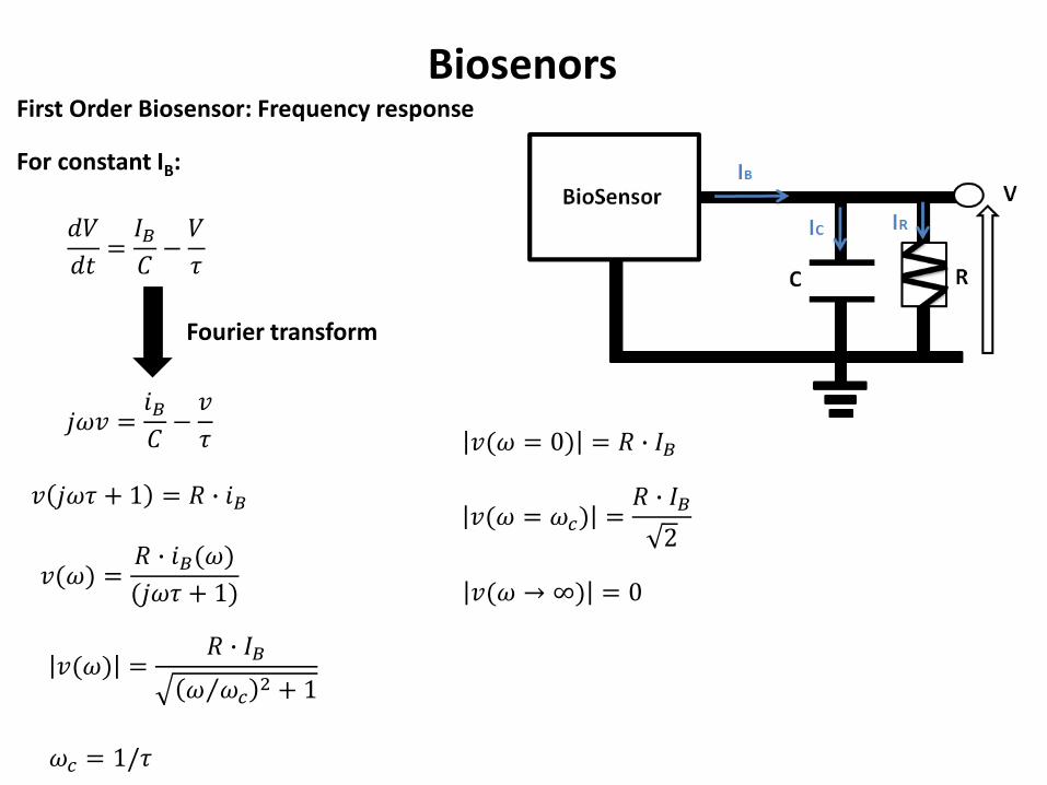
First Order Biosensor Frequency response
Biosenors
For constant IB
119889119881
119889119905=
119868119861119862minus119881
120591
119895120596119907 =119894119861119862minus119907
120591
119907 119895120596120591 + 1 = 119877 ∙ 119894119861
119907(120596) =119877 ∙ 119894119861(120596)
(119895120596120591 + 1)
120596119888 = 1120591
Fourier transform
119907(120596 = 0) = 119877 ∙ 119868119861
119907(120596 rarr infin) = 0
119907(120596) =119877 ∙ 119868119861
120596 1205961198882 + 1
119907(120596 = 120596119888) =119877 ∙ 119868119861
2
First Order Biosensor Frequency response
Biosenors
119907(120596) =119877 ∙ 119868119861
120596 1205961198882 + 1
120596119888 = 1119877119862
119907(120596 = 0) = 119877 ∙ 119868119861
119907(120596 rarr infin) = 0
Low pass filter every input signal with frequency higher ωC
will be cut-off
119907(120596 = 120596119888) =119877 ∙ 119868119861
2
log 1 2 asymp minus015
Low pass filter
Biosenors
ωb gt ωc V=0
sin 120596119887119905
Fourier transform
120575(120596 minus 120596119887)
ωb lt ωc V=Biological Signal
Therefore it is important to design the biosensor physical parameters to set the value of RC (eg dimensions )
119907(120596) =119877 ∙ 119894119861(120596)
(119895120596120591 + 1)
119907 120596 = 119894119861(120596) ∙ 119867119871119875119865(120596)
First Order Biosensor Frequency response
Biosenors
We can arrive to the same results by KCL and KVL
The impedance of R does not depend on the frequency (ZR=R)The impedance of C depends on the frequency (ZC=1jωC)
119881 = 119868119861 ∙ (119885119877||119885119862)
119881 = 119868119861119885119877 ∙ 119885119862119885119877 + 119885119862
119881 = 119868119861
119877 ∙1
119895120596119862
119877 +1
119895120596119862
119881 = 119868119861
119877 ∙1
119895120596119862119895120596119862119877 + 1
119895120596119862
119881 = 119868119861119877
119895120596119877119862 + 1
119881 = 119868119861119877
(120596119877119862)2+1
Biosensor converts one type of energy to electrical energyPhotodiode is pn junction that converts light to electrical energy
Biosenors -Photodiode
119862119889119881
119889119905+119881
119877= 119868119871119894119892ℎ119905 minus 119868119863119894119900119889119890
119868119863119894119900119889119890 = 119868119889119886119903119896(119890 119902119881 119870119879 minus 1)
Low pass filter
Light increases the
dark current
119877 =119889119881
119889119868=
119870119879
119902 ∙ 119868
C is the junction capacitance
Biosensor converts one type of energy to electrical energy
Piezoelectricity convert mechanical energy to electrical energyMeasure pressure and ultrasound waves
Biosenors - Piezoelectricity
It is reversbile an applied mechanical stress will generate a voltage and an applied voltage will change the shape of the solid by a small amount (up to a 4 change in volume)
Convert deflectiondisplacement to charge generator
Kxq K is a constant depends on the material
X is a deflection
R Sensor leakage resistance
C Sensor capacitance
Piezoelectric crystal (quartz)
x
AC r0
Biosenors - Piezoelectricity
Changes in x cause to change in the charge and producing a current
Convert charge generator to current generator
119868119861 =119889119902
119889119905= 119870
119889119909
119889119905
119862119889119881
119889119905+119881
119877= 119870
119889119909
119889119905
119889119881
119889119905= 119870119878
119889119909
119889119905minus119881
120591
Ks = KC sensitivity Vm
= RC time constant
Fourier transform
119895120596119907 = 119870119878 ∙ 119895120596119909(120596) minus119907
120591
119907(120596) =119870119878119895120596120591
1 + 119895120596120591∙ 119909(120596)
Biosenors - Piezoelectricity
Ks = KC sensitivity Vm
= RC time constant
119907(120596) =119870119878 ∙ 120596 120596119888
120596 1205961198882 + 1
∙ 119909(120596)
ωb lt ωc V=0
ωb gt ωc V ~ x
High Pass filter (HPF)
Electrochemical Biosenors
Electrochemistry interfacing electrode with electrolyte Oxidation Ions that lose their electronsReduction Ions that gain new electrons
Convert biochemical reactions to electrical signal
Electrochemical Biosenors
Equivalent electrical circuit of electrochemical cells
Rct Charge transfer resistance due to transfer of electrons from ions to electrodeCdl Double layer capacitor ndashaccumulation of charge in the interface between the electrolyte and electrodeRS series resistance ndash electrolyte solution resistance
119885119890119902 = 119877119904 +119877119888119905
1 + 119895 ∙ 120596 ∙ 119877119888119905 ∙ 119862119889119897
LPF
Amplifier
An input signals (currentvoltage) is amplified to a larger output signals (currentvoltage)
Features1 Linearity (wide linear range)2 High Gain3 Vin=0 Vout=04 High signal to noise ratio5 Stability at time (One dominant half time)6 Stable gain (not depend on circuit parameters VDD temperature hellip)
Amplifier
Amplifier
bull Voltage amplifier
119907119900119906119905 = 119860119907 ∙ 119907119894119899
Vin ndashinputVout ndashoutputAv ndash voltage gain [db]Ri is input resistanceRo output resistanceRS source resistanceRL Load Resistance
119907119894119899 = 119907119904 ∙119877119894
119877119894 + 119877119878 119907119900119906119905 = 119860119907119907119894119899 ∙119877119871
119877119871+119877119874
119907119900119906119905 = 119860119907119907119904 ∙119877119894
119877119894+119877119878∙
119877119871
119877119871+119877119874
119860119907119890119891119891 =119907119900119906119905
119907119904= 119860119907 ∙
119877119894
119877119894+119877119878∙
119877119871
119877119871+119877119874
20 log 119860119907 [119889119861] decibels
Amplifier
Differential amplifier
Reject common noise
∆119881119894119899 = 1198811198941198991 minus 1198811198941198992 = 1198811198941198991 + ∆ minus 1198811198941198992 minus ∆
∆119881119894119899 = 1198811198941198991 minus 1198811198941198992
)119881119900119906119905 = 119860 ∙ (1198811198941198991 minus 1198811198941198992
Negative feedbackNegative feedback loop when the output of the system feed it back to control and reduce his activity
)119881119900119906119905 = 119860 ∙ (1198811198941198991 minus 1198811198941198992
1198811198941198992 = 120573 ∙ 119881119900119906119905
Open loop equation
Negative feedback loop equation
rArr 119881119900119906119905= 119860 ∙ 1198811198941198991 minus 120573 ∙ 119881119900119906119905
119933119952119958119957 = 119933119946119951120783 ∙119912
120783 + 120631 ∙ 119912Blackrsquos Formula
β∙Agtgt1 Vout=Vin1βNegative feedback can increase the stability
Analog-to-digital converts
Noise accumulated in analog circuits
Solution Digital circuit
noise hampers our ability to distinguish between small differences in value mdasheg between 31V and 32V
Digital circuits1 Device of two states (OFFON) or (01)
119881119900119906119905 = 119881119874119873 119881119894119899gt 119881119905ℎ119881119900119891119891 119881119894119899 lt 119881119905ℎ
2 Computation arises from logic functions (Boolean algebra) using basic logic gates
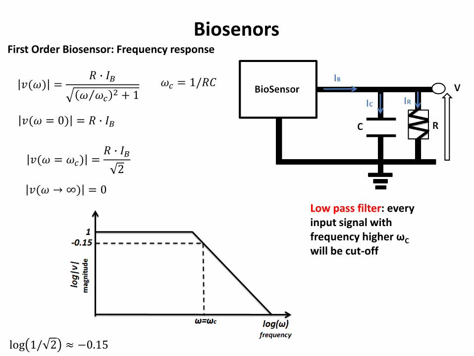
First Order Biosensor Frequency response
Biosenors
119907(120596) =119877 ∙ 119868119861
120596 1205961198882 + 1
120596119888 = 1119877119862
119907(120596 = 0) = 119877 ∙ 119868119861
119907(120596 rarr infin) = 0
Low pass filter every input signal with frequency higher ωC
will be cut-off
119907(120596 = 120596119888) =119877 ∙ 119868119861
2
log 1 2 asymp minus015
Low pass filter
Biosenors
ωb gt ωc V=0
sin 120596119887119905
Fourier transform
120575(120596 minus 120596119887)
ωb lt ωc V=Biological Signal
Therefore it is important to design the biosensor physical parameters to set the value of RC (eg dimensions )
119907(120596) =119877 ∙ 119894119861(120596)
(119895120596120591 + 1)
119907 120596 = 119894119861(120596) ∙ 119867119871119875119865(120596)
First Order Biosensor Frequency response
Biosenors
We can arrive to the same results by KCL and KVL
The impedance of R does not depend on the frequency (ZR=R)The impedance of C depends on the frequency (ZC=1jωC)
119881 = 119868119861 ∙ (119885119877||119885119862)
119881 = 119868119861119885119877 ∙ 119885119862119885119877 + 119885119862
119881 = 119868119861
119877 ∙1
119895120596119862
119877 +1
119895120596119862
119881 = 119868119861
119877 ∙1
119895120596119862119895120596119862119877 + 1
119895120596119862
119881 = 119868119861119877
119895120596119877119862 + 1
119881 = 119868119861119877
(120596119877119862)2+1
Biosensor converts one type of energy to electrical energyPhotodiode is pn junction that converts light to electrical energy
Biosenors -Photodiode
119862119889119881
119889119905+119881
119877= 119868119871119894119892ℎ119905 minus 119868119863119894119900119889119890
119868119863119894119900119889119890 = 119868119889119886119903119896(119890 119902119881 119870119879 minus 1)
Low pass filter
Light increases the
dark current
119877 =119889119881
119889119868=
119870119879
119902 ∙ 119868
C is the junction capacitance
Biosensor converts one type of energy to electrical energy
Piezoelectricity convert mechanical energy to electrical energyMeasure pressure and ultrasound waves
Biosenors - Piezoelectricity
It is reversbile an applied mechanical stress will generate a voltage and an applied voltage will change the shape of the solid by a small amount (up to a 4 change in volume)
Convert deflectiondisplacement to charge generator
Kxq K is a constant depends on the material
X is a deflection
R Sensor leakage resistance
C Sensor capacitance
Piezoelectric crystal (quartz)
x
AC r0
Biosenors - Piezoelectricity
Changes in x cause to change in the charge and producing a current
Convert charge generator to current generator
119868119861 =119889119902
119889119905= 119870
119889119909
119889119905
119862119889119881
119889119905+119881
119877= 119870
119889119909
119889119905
119889119881
119889119905= 119870119878
119889119909
119889119905minus119881
120591
Ks = KC sensitivity Vm
= RC time constant
Fourier transform
119895120596119907 = 119870119878 ∙ 119895120596119909(120596) minus119907
120591
119907(120596) =119870119878119895120596120591
1 + 119895120596120591∙ 119909(120596)
Biosenors - Piezoelectricity
Ks = KC sensitivity Vm
= RC time constant
119907(120596) =119870119878 ∙ 120596 120596119888
120596 1205961198882 + 1
∙ 119909(120596)
ωb lt ωc V=0
ωb gt ωc V ~ x
High Pass filter (HPF)
Electrochemical Biosenors
Electrochemistry interfacing electrode with electrolyte Oxidation Ions that lose their electronsReduction Ions that gain new electrons
Convert biochemical reactions to electrical signal
Electrochemical Biosenors
Equivalent electrical circuit of electrochemical cells
Rct Charge transfer resistance due to transfer of electrons from ions to electrodeCdl Double layer capacitor ndashaccumulation of charge in the interface between the electrolyte and electrodeRS series resistance ndash electrolyte solution resistance
119885119890119902 = 119877119904 +119877119888119905
1 + 119895 ∙ 120596 ∙ 119877119888119905 ∙ 119862119889119897
LPF
Amplifier
An input signals (currentvoltage) is amplified to a larger output signals (currentvoltage)
Features1 Linearity (wide linear range)2 High Gain3 Vin=0 Vout=04 High signal to noise ratio5 Stability at time (One dominant half time)6 Stable gain (not depend on circuit parameters VDD temperature hellip)
Amplifier
Amplifier
bull Voltage amplifier
119907119900119906119905 = 119860119907 ∙ 119907119894119899
Vin ndashinputVout ndashoutputAv ndash voltage gain [db]Ri is input resistanceRo output resistanceRS source resistanceRL Load Resistance
119907119894119899 = 119907119904 ∙119877119894
119877119894 + 119877119878 119907119900119906119905 = 119860119907119907119894119899 ∙119877119871
119877119871+119877119874
119907119900119906119905 = 119860119907119907119904 ∙119877119894
119877119894+119877119878∙
119877119871
119877119871+119877119874
119860119907119890119891119891 =119907119900119906119905
119907119904= 119860119907 ∙
119877119894
119877119894+119877119878∙
119877119871
119877119871+119877119874
20 log 119860119907 [119889119861] decibels
Amplifier
Differential amplifier
Reject common noise
∆119881119894119899 = 1198811198941198991 minus 1198811198941198992 = 1198811198941198991 + ∆ minus 1198811198941198992 minus ∆
∆119881119894119899 = 1198811198941198991 minus 1198811198941198992
)119881119900119906119905 = 119860 ∙ (1198811198941198991 minus 1198811198941198992
Negative feedbackNegative feedback loop when the output of the system feed it back to control and reduce his activity
)119881119900119906119905 = 119860 ∙ (1198811198941198991 minus 1198811198941198992
1198811198941198992 = 120573 ∙ 119881119900119906119905
Open loop equation
Negative feedback loop equation
rArr 119881119900119906119905= 119860 ∙ 1198811198941198991 minus 120573 ∙ 119881119900119906119905
119933119952119958119957 = 119933119946119951120783 ∙119912
120783 + 120631 ∙ 119912Blackrsquos Formula
β∙Agtgt1 Vout=Vin1βNegative feedback can increase the stability
Analog-to-digital converts
Noise accumulated in analog circuits
Solution Digital circuit
noise hampers our ability to distinguish between small differences in value mdasheg between 31V and 32V
Digital circuits1 Device of two states (OFFON) or (01)
119881119900119906119905 = 119881119874119873 119881119894119899gt 119881119905ℎ119881119900119891119891 119881119894119899 lt 119881119905ℎ
2 Computation arises from logic functions (Boolean algebra) using basic logic gates
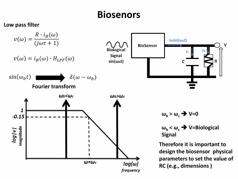
Low pass filter
Biosenors
ωb gt ωc V=0
sin 120596119887119905
Fourier transform
120575(120596 minus 120596119887)
ωb lt ωc V=Biological Signal
Therefore it is important to design the biosensor physical parameters to set the value of RC (eg dimensions )
119907(120596) =119877 ∙ 119894119861(120596)
(119895120596120591 + 1)
119907 120596 = 119894119861(120596) ∙ 119867119871119875119865(120596)
First Order Biosensor Frequency response
Biosenors
We can arrive to the same results by KCL and KVL
The impedance of R does not depend on the frequency (ZR=R)The impedance of C depends on the frequency (ZC=1jωC)
119881 = 119868119861 ∙ (119885119877||119885119862)
119881 = 119868119861119885119877 ∙ 119885119862119885119877 + 119885119862
119881 = 119868119861
119877 ∙1
119895120596119862
119877 +1
119895120596119862
119881 = 119868119861
119877 ∙1
119895120596119862119895120596119862119877 + 1
119895120596119862
119881 = 119868119861119877
119895120596119877119862 + 1
119881 = 119868119861119877
(120596119877119862)2+1
Biosensor converts one type of energy to electrical energyPhotodiode is pn junction that converts light to electrical energy
Biosenors -Photodiode
119862119889119881
119889119905+119881
119877= 119868119871119894119892ℎ119905 minus 119868119863119894119900119889119890
119868119863119894119900119889119890 = 119868119889119886119903119896(119890 119902119881 119870119879 minus 1)
Low pass filter
Light increases the
dark current
119877 =119889119881
119889119868=
119870119879
119902 ∙ 119868
C is the junction capacitance
Biosensor converts one type of energy to electrical energy
Piezoelectricity convert mechanical energy to electrical energyMeasure pressure and ultrasound waves
Biosenors - Piezoelectricity
It is reversbile an applied mechanical stress will generate a voltage and an applied voltage will change the shape of the solid by a small amount (up to a 4 change in volume)
Convert deflectiondisplacement to charge generator
Kxq K is a constant depends on the material
X is a deflection
R Sensor leakage resistance
C Sensor capacitance
Piezoelectric crystal (quartz)
x
AC r0
Biosenors - Piezoelectricity
Changes in x cause to change in the charge and producing a current
Convert charge generator to current generator
119868119861 =119889119902
119889119905= 119870
119889119909
119889119905
119862119889119881
119889119905+119881
119877= 119870
119889119909
119889119905
119889119881
119889119905= 119870119878
119889119909
119889119905minus119881
120591
Ks = KC sensitivity Vm
= RC time constant
Fourier transform
119895120596119907 = 119870119878 ∙ 119895120596119909(120596) minus119907
120591
119907(120596) =119870119878119895120596120591
1 + 119895120596120591∙ 119909(120596)
Biosenors - Piezoelectricity
Ks = KC sensitivity Vm
= RC time constant
119907(120596) =119870119878 ∙ 120596 120596119888
120596 1205961198882 + 1
∙ 119909(120596)
ωb lt ωc V=0
ωb gt ωc V ~ x
High Pass filter (HPF)
Electrochemical Biosenors
Electrochemistry interfacing electrode with electrolyte Oxidation Ions that lose their electronsReduction Ions that gain new electrons
Convert biochemical reactions to electrical signal
Electrochemical Biosenors
Equivalent electrical circuit of electrochemical cells
Rct Charge transfer resistance due to transfer of electrons from ions to electrodeCdl Double layer capacitor ndashaccumulation of charge in the interface between the electrolyte and electrodeRS series resistance ndash electrolyte solution resistance
119885119890119902 = 119877119904 +119877119888119905
1 + 119895 ∙ 120596 ∙ 119877119888119905 ∙ 119862119889119897
LPF
Amplifier
An input signals (currentvoltage) is amplified to a larger output signals (currentvoltage)
Features1 Linearity (wide linear range)2 High Gain3 Vin=0 Vout=04 High signal to noise ratio5 Stability at time (One dominant half time)6 Stable gain (not depend on circuit parameters VDD temperature hellip)
Amplifier
Amplifier
bull Voltage amplifier
119907119900119906119905 = 119860119907 ∙ 119907119894119899
Vin ndashinputVout ndashoutputAv ndash voltage gain [db]Ri is input resistanceRo output resistanceRS source resistanceRL Load Resistance
119907119894119899 = 119907119904 ∙119877119894
119877119894 + 119877119878 119907119900119906119905 = 119860119907119907119894119899 ∙119877119871
119877119871+119877119874
119907119900119906119905 = 119860119907119907119904 ∙119877119894
119877119894+119877119878∙
119877119871
119877119871+119877119874
119860119907119890119891119891 =119907119900119906119905
119907119904= 119860119907 ∙
119877119894
119877119894+119877119878∙
119877119871
119877119871+119877119874
20 log 119860119907 [119889119861] decibels
Amplifier
Differential amplifier
Reject common noise
∆119881119894119899 = 1198811198941198991 minus 1198811198941198992 = 1198811198941198991 + ∆ minus 1198811198941198992 minus ∆
∆119881119894119899 = 1198811198941198991 minus 1198811198941198992
)119881119900119906119905 = 119860 ∙ (1198811198941198991 minus 1198811198941198992
Negative feedbackNegative feedback loop when the output of the system feed it back to control and reduce his activity
)119881119900119906119905 = 119860 ∙ (1198811198941198991 minus 1198811198941198992
1198811198941198992 = 120573 ∙ 119881119900119906119905
Open loop equation
Negative feedback loop equation
rArr 119881119900119906119905= 119860 ∙ 1198811198941198991 minus 120573 ∙ 119881119900119906119905
119933119952119958119957 = 119933119946119951120783 ∙119912
120783 + 120631 ∙ 119912Blackrsquos Formula
β∙Agtgt1 Vout=Vin1βNegative feedback can increase the stability
Analog-to-digital converts
Noise accumulated in analog circuits
Solution Digital circuit
noise hampers our ability to distinguish between small differences in value mdasheg between 31V and 32V
Digital circuits1 Device of two states (OFFON) or (01)
119881119900119906119905 = 119881119874119873 119881119894119899gt 119881119905ℎ119881119900119891119891 119881119894119899 lt 119881119905ℎ
2 Computation arises from logic functions (Boolean algebra) using basic logic gates
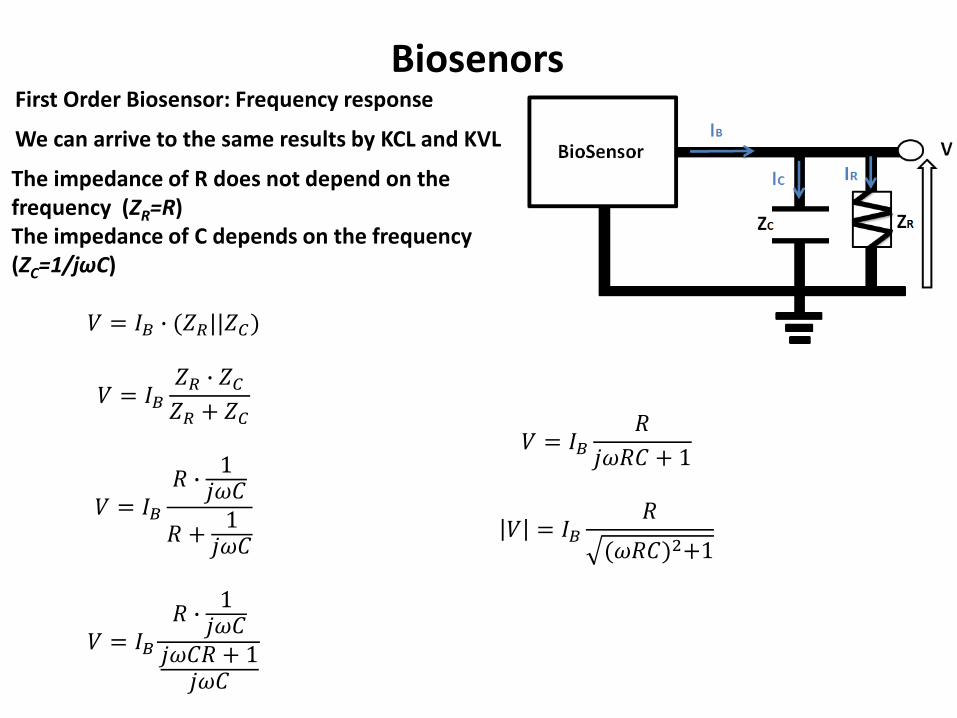
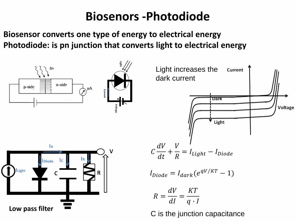
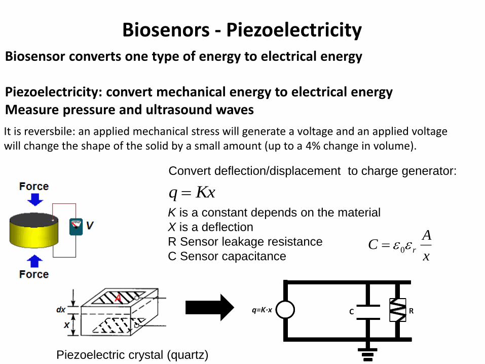
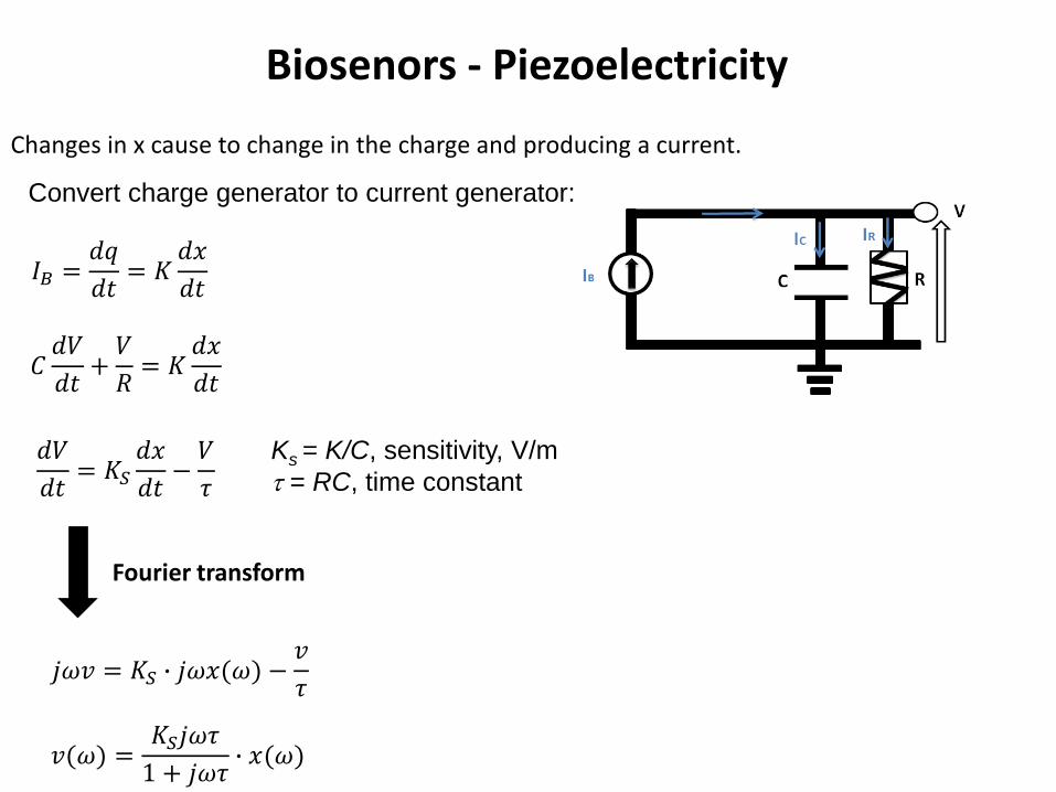
Biosenors - Piezoelectricity
Changes in x cause to change in the charge and producing a current
Convert charge generator to current generator
119868119861 =119889119902
119889119905= 119870
119889119909
119889119905
119862119889119881
119889119905+119881
119877= 119870
119889119909
119889119905
119889119881
119889119905= 119870119878
119889119909
119889119905minus119881
120591
Ks = KC sensitivity Vm
= RC time constant
Fourier transform
119895120596119907 = 119870119878 ∙ 119895120596119909(120596) minus119907
120591
119907(120596) =119870119878119895120596120591
1 + 119895120596120591∙ 119909(120596)
Biosenors - Piezoelectricity
Ks = KC sensitivity Vm
= RC time constant
119907(120596) =119870119878 ∙ 120596 120596119888
120596 1205961198882 + 1
∙ 119909(120596)
ωb lt ωc V=0
ωb gt ωc V ~ x
High Pass filter (HPF)
Electrochemical Biosenors
Electrochemistry interfacing electrode with electrolyte Oxidation Ions that lose their electronsReduction Ions that gain new electrons
Convert biochemical reactions to electrical signal
Electrochemical Biosenors
Equivalent electrical circuit of electrochemical cells
Rct Charge transfer resistance due to transfer of electrons from ions to electrodeCdl Double layer capacitor ndashaccumulation of charge in the interface between the electrolyte and electrodeRS series resistance ndash electrolyte solution resistance
119885119890119902 = 119877119904 +119877119888119905
1 + 119895 ∙ 120596 ∙ 119877119888119905 ∙ 119862119889119897
LPF
Amplifier
An input signals (currentvoltage) is amplified to a larger output signals (currentvoltage)
Features1 Linearity (wide linear range)2 High Gain3 Vin=0 Vout=04 High signal to noise ratio5 Stability at time (One dominant half time)6 Stable gain (not depend on circuit parameters VDD temperature hellip)
Amplifier
Amplifier
bull Voltage amplifier
119907119900119906119905 = 119860119907 ∙ 119907119894119899
Vin ndashinputVout ndashoutputAv ndash voltage gain [db]Ri is input resistanceRo output resistanceRS source resistanceRL Load Resistance
119907119894119899 = 119907119904 ∙119877119894
119877119894 + 119877119878 119907119900119906119905 = 119860119907119907119894119899 ∙119877119871
119877119871+119877119874
119907119900119906119905 = 119860119907119907119904 ∙119877119894
119877119894+119877119878∙
119877119871
119877119871+119877119874
119860119907119890119891119891 =119907119900119906119905
119907119904= 119860119907 ∙
119877119894
119877119894+119877119878∙
119877119871
119877119871+119877119874
20 log 119860119907 [119889119861] decibels
Amplifier
Differential amplifier
Reject common noise
∆119881119894119899 = 1198811198941198991 minus 1198811198941198992 = 1198811198941198991 + ∆ minus 1198811198941198992 minus ∆
∆119881119894119899 = 1198811198941198991 minus 1198811198941198992
)119881119900119906119905 = 119860 ∙ (1198811198941198991 minus 1198811198941198992
Negative feedbackNegative feedback loop when the output of the system feed it back to control and reduce his activity
)119881119900119906119905 = 119860 ∙ (1198811198941198991 minus 1198811198941198992
1198811198941198992 = 120573 ∙ 119881119900119906119905
Open loop equation
Negative feedback loop equation
rArr 119881119900119906119905= 119860 ∙ 1198811198941198991 minus 120573 ∙ 119881119900119906119905
119933119952119958119957 = 119933119946119951120783 ∙119912
120783 + 120631 ∙ 119912Blackrsquos Formula
β∙Agtgt1 Vout=Vin1βNegative feedback can increase the stability
Analog-to-digital converts
Noise accumulated in analog circuits
Solution Digital circuit
noise hampers our ability to distinguish between small differences in value mdasheg between 31V and 32V
Digital circuits1 Device of two states (OFFON) or (01)
119881119900119906119905 = 119881119874119873 119881119894119899gt 119881119905ℎ119881119900119891119891 119881119894119899 lt 119881119905ℎ
2 Computation arises from logic functions (Boolean algebra) using basic logic gates
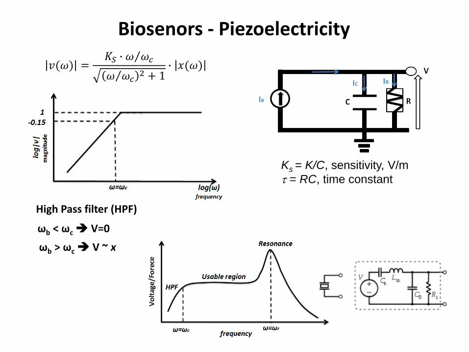
Biosenors - Piezoelectricity
Ks = KC sensitivity Vm
= RC time constant
119907(120596) =119870119878 ∙ 120596 120596119888
120596 1205961198882 + 1
∙ 119909(120596)
ωb lt ωc V=0
ωb gt ωc V ~ x
High Pass filter (HPF)
Electrochemical Biosenors
Electrochemistry interfacing electrode with electrolyte Oxidation Ions that lose their electronsReduction Ions that gain new electrons
Convert biochemical reactions to electrical signal
Electrochemical Biosenors
Equivalent electrical circuit of electrochemical cells
Rct Charge transfer resistance due to transfer of electrons from ions to electrodeCdl Double layer capacitor ndashaccumulation of charge in the interface between the electrolyte and electrodeRS series resistance ndash electrolyte solution resistance
119885119890119902 = 119877119904 +119877119888119905
1 + 119895 ∙ 120596 ∙ 119877119888119905 ∙ 119862119889119897
LPF
Amplifier
An input signals (currentvoltage) is amplified to a larger output signals (currentvoltage)
Features1 Linearity (wide linear range)2 High Gain3 Vin=0 Vout=04 High signal to noise ratio5 Stability at time (One dominant half time)6 Stable gain (not depend on circuit parameters VDD temperature hellip)
Amplifier
Amplifier
bull Voltage amplifier
119907119900119906119905 = 119860119907 ∙ 119907119894119899
Vin ndashinputVout ndashoutputAv ndash voltage gain [db]Ri is input resistanceRo output resistanceRS source resistanceRL Load Resistance
119907119894119899 = 119907119904 ∙119877119894
119877119894 + 119877119878 119907119900119906119905 = 119860119907119907119894119899 ∙119877119871
119877119871+119877119874
119907119900119906119905 = 119860119907119907119904 ∙119877119894
119877119894+119877119878∙
119877119871
119877119871+119877119874
119860119907119890119891119891 =119907119900119906119905
119907119904= 119860119907 ∙
119877119894
119877119894+119877119878∙
119877119871
119877119871+119877119874
20 log 119860119907 [119889119861] decibels
Amplifier
Differential amplifier
Reject common noise
∆119881119894119899 = 1198811198941198991 minus 1198811198941198992 = 1198811198941198991 + ∆ minus 1198811198941198992 minus ∆
∆119881119894119899 = 1198811198941198991 minus 1198811198941198992
)119881119900119906119905 = 119860 ∙ (1198811198941198991 minus 1198811198941198992
Negative feedbackNegative feedback loop when the output of the system feed it back to control and reduce his activity
)119881119900119906119905 = 119860 ∙ (1198811198941198991 minus 1198811198941198992
1198811198941198992 = 120573 ∙ 119881119900119906119905
Open loop equation
Negative feedback loop equation
rArr 119881119900119906119905= 119860 ∙ 1198811198941198991 minus 120573 ∙ 119881119900119906119905
119933119952119958119957 = 119933119946119951120783 ∙119912
120783 + 120631 ∙ 119912Blackrsquos Formula
β∙Agtgt1 Vout=Vin1βNegative feedback can increase the stability
Analog-to-digital converts
Noise accumulated in analog circuits
Solution Digital circuit
noise hampers our ability to distinguish between small differences in value mdasheg between 31V and 32V
Digital circuits1 Device of two states (OFFON) or (01)
119881119900119906119905 = 119881119874119873 119881119894119899gt 119881119905ℎ119881119900119891119891 119881119894119899 lt 119881119905ℎ
2 Computation arises from logic functions (Boolean algebra) using basic logic gates
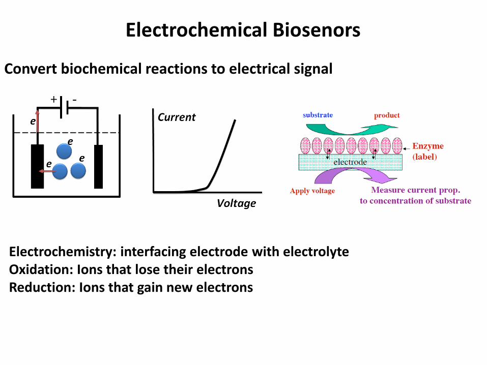
Electrochemical Biosenors
Electrochemistry interfacing electrode with electrolyte Oxidation Ions that lose their electronsReduction Ions that gain new electrons
Convert biochemical reactions to electrical signal
Electrochemical Biosenors
Equivalent electrical circuit of electrochemical cells
Rct Charge transfer resistance due to transfer of electrons from ions to electrodeCdl Double layer capacitor ndashaccumulation of charge in the interface between the electrolyte and electrodeRS series resistance ndash electrolyte solution resistance
119885119890119902 = 119877119904 +119877119888119905
1 + 119895 ∙ 120596 ∙ 119877119888119905 ∙ 119862119889119897
LPF
Amplifier
An input signals (currentvoltage) is amplified to a larger output signals (currentvoltage)
Features1 Linearity (wide linear range)2 High Gain3 Vin=0 Vout=04 High signal to noise ratio5 Stability at time (One dominant half time)6 Stable gain (not depend on circuit parameters VDD temperature hellip)
Amplifier
Amplifier
bull Voltage amplifier
119907119900119906119905 = 119860119907 ∙ 119907119894119899
Vin ndashinputVout ndashoutputAv ndash voltage gain [db]Ri is input resistanceRo output resistanceRS source resistanceRL Load Resistance
119907119894119899 = 119907119904 ∙119877119894
119877119894 + 119877119878 119907119900119906119905 = 119860119907119907119894119899 ∙119877119871
119877119871+119877119874
119907119900119906119905 = 119860119907119907119904 ∙119877119894
119877119894+119877119878∙
119877119871
119877119871+119877119874
119860119907119890119891119891 =119907119900119906119905
119907119904= 119860119907 ∙
119877119894
119877119894+119877119878∙
119877119871
119877119871+119877119874
20 log 119860119907 [119889119861] decibels
Amplifier
Differential amplifier
Reject common noise
∆119881119894119899 = 1198811198941198991 minus 1198811198941198992 = 1198811198941198991 + ∆ minus 1198811198941198992 minus ∆
∆119881119894119899 = 1198811198941198991 minus 1198811198941198992
)119881119900119906119905 = 119860 ∙ (1198811198941198991 minus 1198811198941198992
Negative feedbackNegative feedback loop when the output of the system feed it back to control and reduce his activity
)119881119900119906119905 = 119860 ∙ (1198811198941198991 minus 1198811198941198992
1198811198941198992 = 120573 ∙ 119881119900119906119905
Open loop equation
Negative feedback loop equation
rArr 119881119900119906119905= 119860 ∙ 1198811198941198991 minus 120573 ∙ 119881119900119906119905
119933119952119958119957 = 119933119946119951120783 ∙119912
120783 + 120631 ∙ 119912Blackrsquos Formula
β∙Agtgt1 Vout=Vin1βNegative feedback can increase the stability
Analog-to-digital converts
Noise accumulated in analog circuits
Solution Digital circuit
noise hampers our ability to distinguish between small differences in value mdasheg between 31V and 32V
Digital circuits1 Device of two states (OFFON) or (01)
119881119900119906119905 = 119881119874119873 119881119894119899gt 119881119905ℎ119881119900119891119891 119881119894119899 lt 119881119905ℎ
2 Computation arises from logic functions (Boolean algebra) using basic logic gates
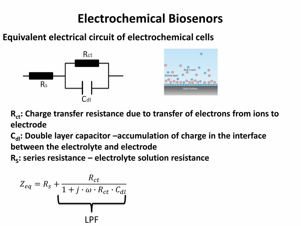
Electrochemical Biosenors
Equivalent electrical circuit of electrochemical cells
Rct Charge transfer resistance due to transfer of electrons from ions to electrodeCdl Double layer capacitor ndashaccumulation of charge in the interface between the electrolyte and electrodeRS series resistance ndash electrolyte solution resistance
119885119890119902 = 119877119904 +119877119888119905
1 + 119895 ∙ 120596 ∙ 119877119888119905 ∙ 119862119889119897
LPF
Amplifier
An input signals (currentvoltage) is amplified to a larger output signals (currentvoltage)
Features1 Linearity (wide linear range)2 High Gain3 Vin=0 Vout=04 High signal to noise ratio5 Stability at time (One dominant half time)6 Stable gain (not depend on circuit parameters VDD temperature hellip)
Amplifier
Amplifier
bull Voltage amplifier
119907119900119906119905 = 119860119907 ∙ 119907119894119899
Vin ndashinputVout ndashoutputAv ndash voltage gain [db]Ri is input resistanceRo output resistanceRS source resistanceRL Load Resistance
119907119894119899 = 119907119904 ∙119877119894
119877119894 + 119877119878 119907119900119906119905 = 119860119907119907119894119899 ∙119877119871
119877119871+119877119874
119907119900119906119905 = 119860119907119907119904 ∙119877119894
119877119894+119877119878∙
119877119871
119877119871+119877119874
119860119907119890119891119891 =119907119900119906119905
119907119904= 119860119907 ∙
119877119894
119877119894+119877119878∙
119877119871
119877119871+119877119874
20 log 119860119907 [119889119861] decibels
Amplifier
Differential amplifier
Reject common noise
∆119881119894119899 = 1198811198941198991 minus 1198811198941198992 = 1198811198941198991 + ∆ minus 1198811198941198992 minus ∆
∆119881119894119899 = 1198811198941198991 minus 1198811198941198992
)119881119900119906119905 = 119860 ∙ (1198811198941198991 minus 1198811198941198992
Negative feedbackNegative feedback loop when the output of the system feed it back to control and reduce his activity
)119881119900119906119905 = 119860 ∙ (1198811198941198991 minus 1198811198941198992
1198811198941198992 = 120573 ∙ 119881119900119906119905
Open loop equation
Negative feedback loop equation
rArr 119881119900119906119905= 119860 ∙ 1198811198941198991 minus 120573 ∙ 119881119900119906119905
119933119952119958119957 = 119933119946119951120783 ∙119912
120783 + 120631 ∙ 119912Blackrsquos Formula
β∙Agtgt1 Vout=Vin1βNegative feedback can increase the stability
Analog-to-digital converts
Noise accumulated in analog circuits
Solution Digital circuit
noise hampers our ability to distinguish between small differences in value mdasheg between 31V and 32V
Digital circuits1 Device of two states (OFFON) or (01)
119881119900119906119905 = 119881119874119873 119881119894119899gt 119881119905ℎ119881119900119891119891 119881119894119899 lt 119881119905ℎ
2 Computation arises from logic functions (Boolean algebra) using basic logic gates
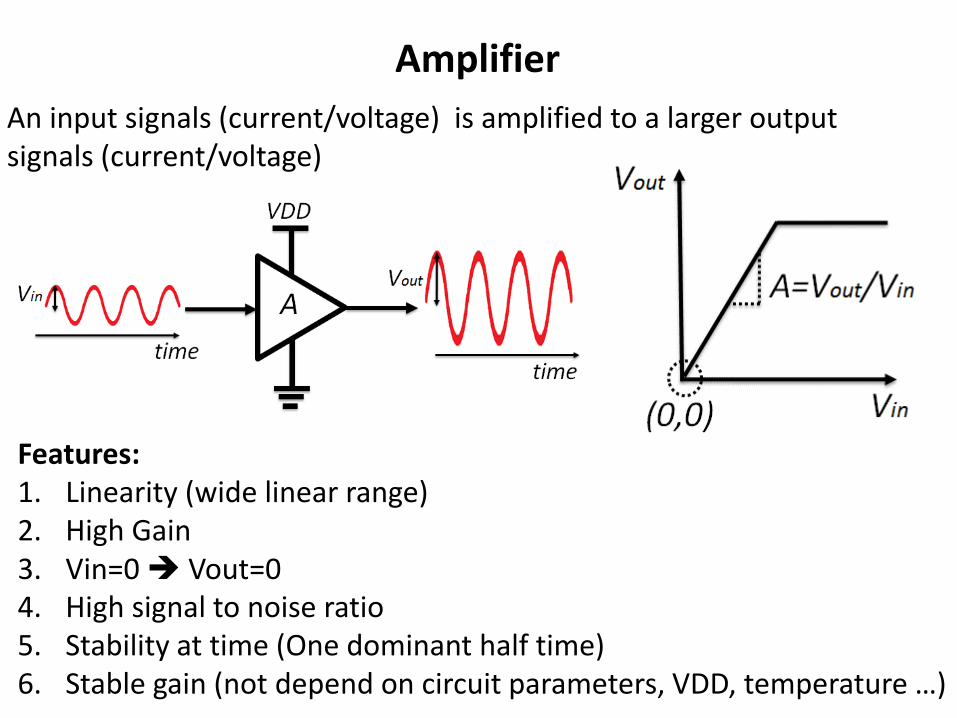
Amplifier
An input signals (currentvoltage) is amplified to a larger output signals (currentvoltage)
Features1 Linearity (wide linear range)2 High Gain3 Vin=0 Vout=04 High signal to noise ratio5 Stability at time (One dominant half time)6 Stable gain (not depend on circuit parameters VDD temperature hellip)
Amplifier
Amplifier
bull Voltage amplifier
119907119900119906119905 = 119860119907 ∙ 119907119894119899
Vin ndashinputVout ndashoutputAv ndash voltage gain [db]Ri is input resistanceRo output resistanceRS source resistanceRL Load Resistance
119907119894119899 = 119907119904 ∙119877119894
119877119894 + 119877119878 119907119900119906119905 = 119860119907119907119894119899 ∙119877119871
119877119871+119877119874
119907119900119906119905 = 119860119907119907119904 ∙119877119894
119877119894+119877119878∙
119877119871
119877119871+119877119874
119860119907119890119891119891 =119907119900119906119905
119907119904= 119860119907 ∙
119877119894
119877119894+119877119878∙
119877119871
119877119871+119877119874
20 log 119860119907 [119889119861] decibels
Amplifier
Differential amplifier
Reject common noise
∆119881119894119899 = 1198811198941198991 minus 1198811198941198992 = 1198811198941198991 + ∆ minus 1198811198941198992 minus ∆
∆119881119894119899 = 1198811198941198991 minus 1198811198941198992
)119881119900119906119905 = 119860 ∙ (1198811198941198991 minus 1198811198941198992
Negative feedbackNegative feedback loop when the output of the system feed it back to control and reduce his activity
)119881119900119906119905 = 119860 ∙ (1198811198941198991 minus 1198811198941198992
1198811198941198992 = 120573 ∙ 119881119900119906119905
Open loop equation
Negative feedback loop equation
rArr 119881119900119906119905= 119860 ∙ 1198811198941198991 minus 120573 ∙ 119881119900119906119905
119933119952119958119957 = 119933119946119951120783 ∙119912
120783 + 120631 ∙ 119912Blackrsquos Formula
β∙Agtgt1 Vout=Vin1βNegative feedback can increase the stability
Analog-to-digital converts
Noise accumulated in analog circuits
Solution Digital circuit
noise hampers our ability to distinguish between small differences in value mdasheg between 31V and 32V
Digital circuits1 Device of two states (OFFON) or (01)
119881119900119906119905 = 119881119874119873 119881119894119899gt 119881119905ℎ119881119900119891119891 119881119894119899 lt 119881119905ℎ
2 Computation arises from logic functions (Boolean algebra) using basic logic gates
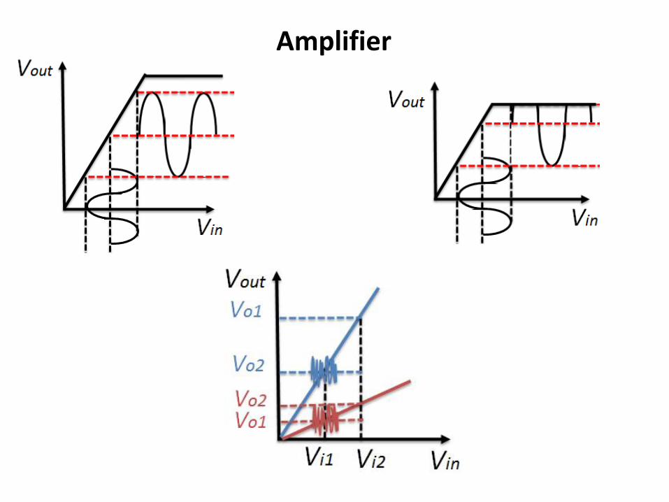
Amplifier
Amplifier
bull Voltage amplifier
119907119900119906119905 = 119860119907 ∙ 119907119894119899
Vin ndashinputVout ndashoutputAv ndash voltage gain [db]Ri is input resistanceRo output resistanceRS source resistanceRL Load Resistance
119907119894119899 = 119907119904 ∙119877119894
119877119894 + 119877119878 119907119900119906119905 = 119860119907119907119894119899 ∙119877119871
119877119871+119877119874
119907119900119906119905 = 119860119907119907119904 ∙119877119894
119877119894+119877119878∙
119877119871
119877119871+119877119874
119860119907119890119891119891 =119907119900119906119905
119907119904= 119860119907 ∙
119877119894
119877119894+119877119878∙
119877119871
119877119871+119877119874
20 log 119860119907 [119889119861] decibels
Amplifier
Differential amplifier
Reject common noise
∆119881119894119899 = 1198811198941198991 minus 1198811198941198992 = 1198811198941198991 + ∆ minus 1198811198941198992 minus ∆
∆119881119894119899 = 1198811198941198991 minus 1198811198941198992
)119881119900119906119905 = 119860 ∙ (1198811198941198991 minus 1198811198941198992
Negative feedbackNegative feedback loop when the output of the system feed it back to control and reduce his activity
)119881119900119906119905 = 119860 ∙ (1198811198941198991 minus 1198811198941198992
1198811198941198992 = 120573 ∙ 119881119900119906119905
Open loop equation
Negative feedback loop equation
rArr 119881119900119906119905= 119860 ∙ 1198811198941198991 minus 120573 ∙ 119881119900119906119905
119933119952119958119957 = 119933119946119951120783 ∙119912
120783 + 120631 ∙ 119912Blackrsquos Formula
β∙Agtgt1 Vout=Vin1βNegative feedback can increase the stability
Analog-to-digital converts
Noise accumulated in analog circuits
Solution Digital circuit
noise hampers our ability to distinguish between small differences in value mdasheg between 31V and 32V
Digital circuits1 Device of two states (OFFON) or (01)
119881119900119906119905 = 119881119874119873 119881119894119899gt 119881119905ℎ119881119900119891119891 119881119894119899 lt 119881119905ℎ
2 Computation arises from logic functions (Boolean algebra) using basic logic gates
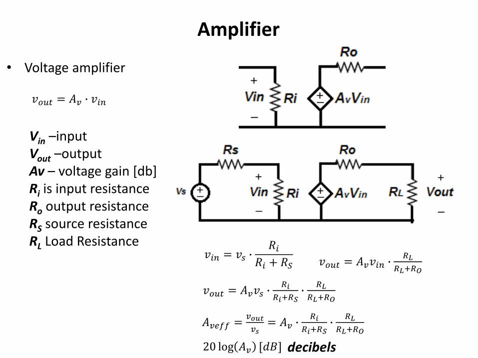
Amplifier
bull Voltage amplifier
119907119900119906119905 = 119860119907 ∙ 119907119894119899
Vin ndashinputVout ndashoutputAv ndash voltage gain [db]Ri is input resistanceRo output resistanceRS source resistanceRL Load Resistance
119907119894119899 = 119907119904 ∙119877119894
119877119894 + 119877119878 119907119900119906119905 = 119860119907119907119894119899 ∙119877119871
119877119871+119877119874
119907119900119906119905 = 119860119907119907119904 ∙119877119894
119877119894+119877119878∙
119877119871
119877119871+119877119874
119860119907119890119891119891 =119907119900119906119905
119907119904= 119860119907 ∙
119877119894
119877119894+119877119878∙
119877119871
119877119871+119877119874
20 log 119860119907 [119889119861] decibels
Amplifier
Differential amplifier
Reject common noise
∆119881119894119899 = 1198811198941198991 minus 1198811198941198992 = 1198811198941198991 + ∆ minus 1198811198941198992 minus ∆
∆119881119894119899 = 1198811198941198991 minus 1198811198941198992
)119881119900119906119905 = 119860 ∙ (1198811198941198991 minus 1198811198941198992
Negative feedbackNegative feedback loop when the output of the system feed it back to control and reduce his activity
)119881119900119906119905 = 119860 ∙ (1198811198941198991 minus 1198811198941198992
1198811198941198992 = 120573 ∙ 119881119900119906119905
Open loop equation
Negative feedback loop equation
rArr 119881119900119906119905= 119860 ∙ 1198811198941198991 minus 120573 ∙ 119881119900119906119905
119933119952119958119957 = 119933119946119951120783 ∙119912
120783 + 120631 ∙ 119912Blackrsquos Formula
β∙Agtgt1 Vout=Vin1βNegative feedback can increase the stability
Analog-to-digital converts
Noise accumulated in analog circuits
Solution Digital circuit
noise hampers our ability to distinguish between small differences in value mdasheg between 31V and 32V
Digital circuits1 Device of two states (OFFON) or (01)
119881119900119906119905 = 119881119874119873 119881119894119899gt 119881119905ℎ119881119900119891119891 119881119894119899 lt 119881119905ℎ
2 Computation arises from logic functions (Boolean algebra) using basic logic gates
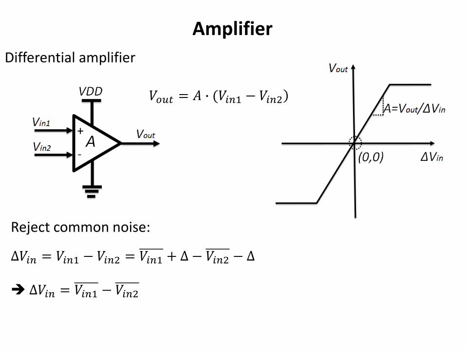
Amplifier
Differential amplifier
Reject common noise
∆119881119894119899 = 1198811198941198991 minus 1198811198941198992 = 1198811198941198991 + ∆ minus 1198811198941198992 minus ∆
∆119881119894119899 = 1198811198941198991 minus 1198811198941198992
)119881119900119906119905 = 119860 ∙ (1198811198941198991 minus 1198811198941198992
Negative feedbackNegative feedback loop when the output of the system feed it back to control and reduce his activity
)119881119900119906119905 = 119860 ∙ (1198811198941198991 minus 1198811198941198992
1198811198941198992 = 120573 ∙ 119881119900119906119905
Open loop equation
Negative feedback loop equation
rArr 119881119900119906119905= 119860 ∙ 1198811198941198991 minus 120573 ∙ 119881119900119906119905
119933119952119958119957 = 119933119946119951120783 ∙119912
120783 + 120631 ∙ 119912Blackrsquos Formula
β∙Agtgt1 Vout=Vin1βNegative feedback can increase the stability
Analog-to-digital converts
Noise accumulated in analog circuits
Solution Digital circuit
noise hampers our ability to distinguish between small differences in value mdasheg between 31V and 32V
Digital circuits1 Device of two states (OFFON) or (01)
119881119900119906119905 = 119881119874119873 119881119894119899gt 119881119905ℎ119881119900119891119891 119881119894119899 lt 119881119905ℎ
2 Computation arises from logic functions (Boolean algebra) using basic logic gates
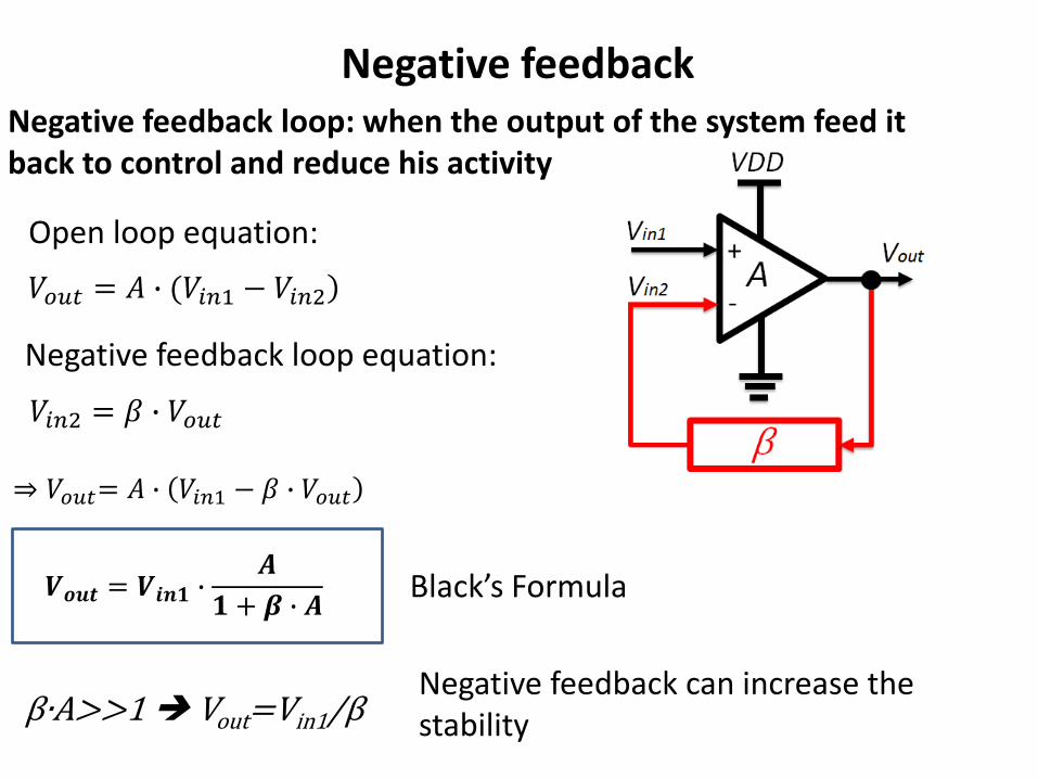
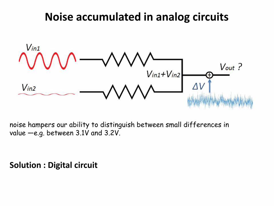
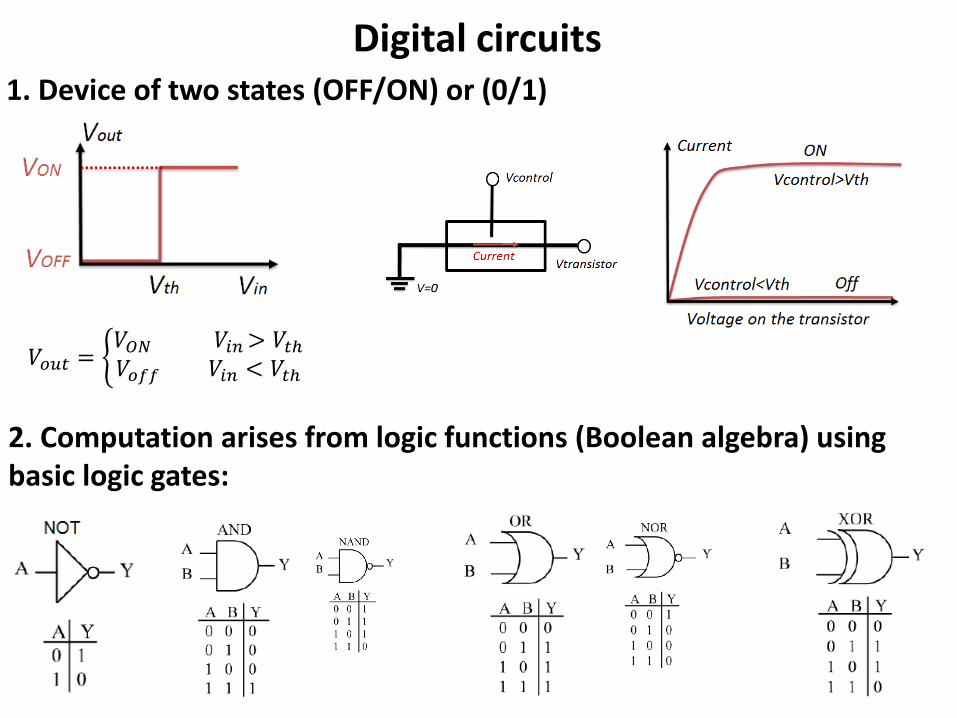
Digital circuits1 Device of two states (OFFON) or (01)
119881119900119906119905 = 119881119874119873 119881119894119899gt 119881119905ℎ119881119900119891119891 119881119894119899 lt 119881119905ℎ
2 Computation arises from logic functions (Boolean algebra) using basic logic gates
Recommended