PROJECT SEMESTERPROJECT SEMESTERJUNE-DECEMBER 2007JUNE-DECEMBER 2007
BY GURSHARAN SINGHBY GURSHARAN SINGH
10552021055202
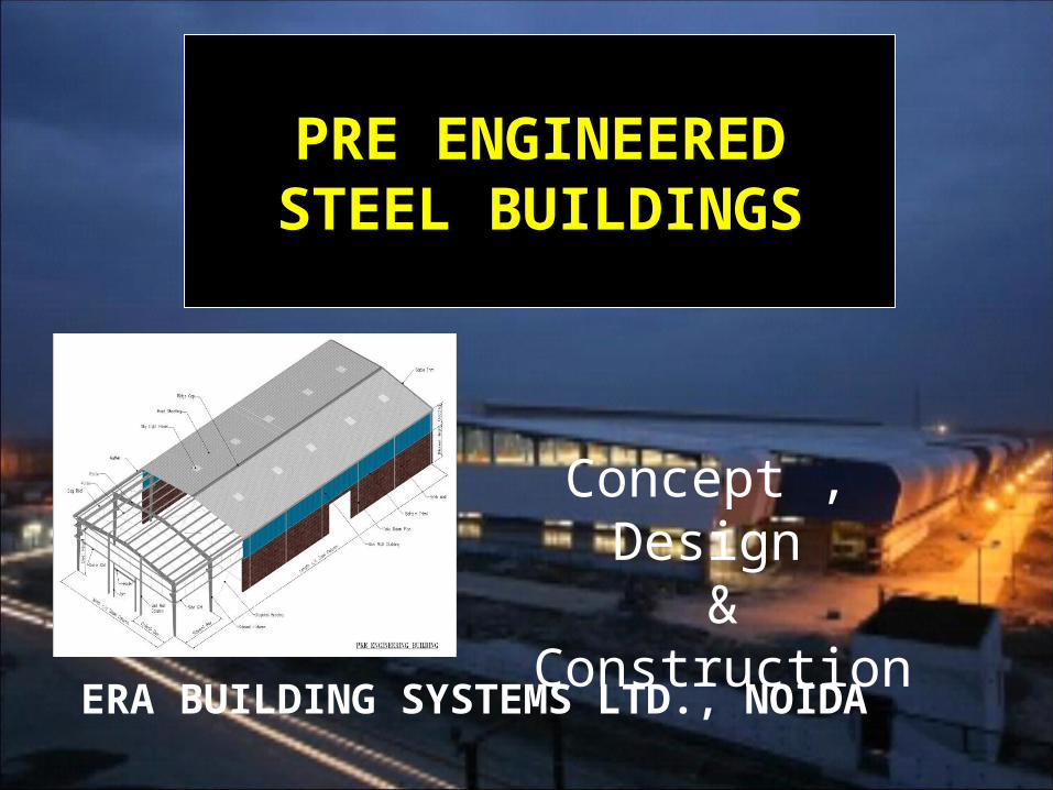
ERA BUILDING SYSTEMS LTD., NOIDA
PRE ENGINEEREDSTEEL BUILDINGS
Concept , Design &
Construction
ERA Group ERA Group
Era Infra Engineering Ltd.Era Infra Engineering Ltd.
Era Building System Ltd.Era Building System Ltd.
Era E-Zone (India) Ltd.Era E-Zone (India) Ltd.
Era Landmarks (India) Ltd.Era Landmarks (India) Ltd.
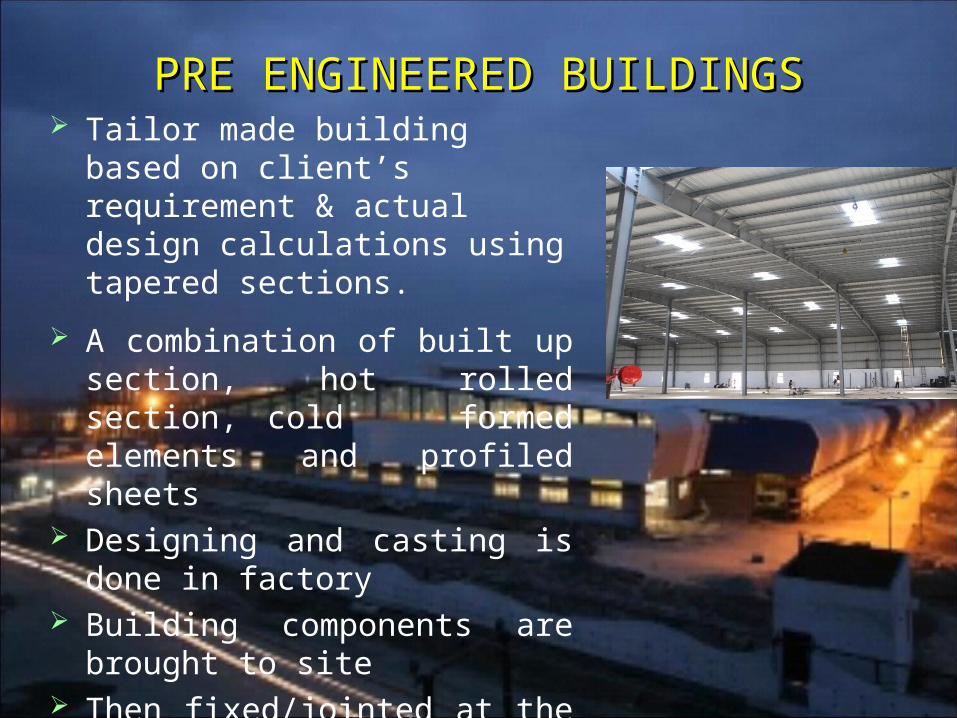
PRE ENGINEERED BUILDINGSPRE ENGINEERED BUILDINGS Tailor made building based on
client’s requirement & actual design calculations using tapered sections.
A combination of built up section, hot rolled section, cold formed elements and profiled sheets
Designing and casting is done in factory
Building components are brought to site
Then fixed/jointed at the site All connections are bolted.
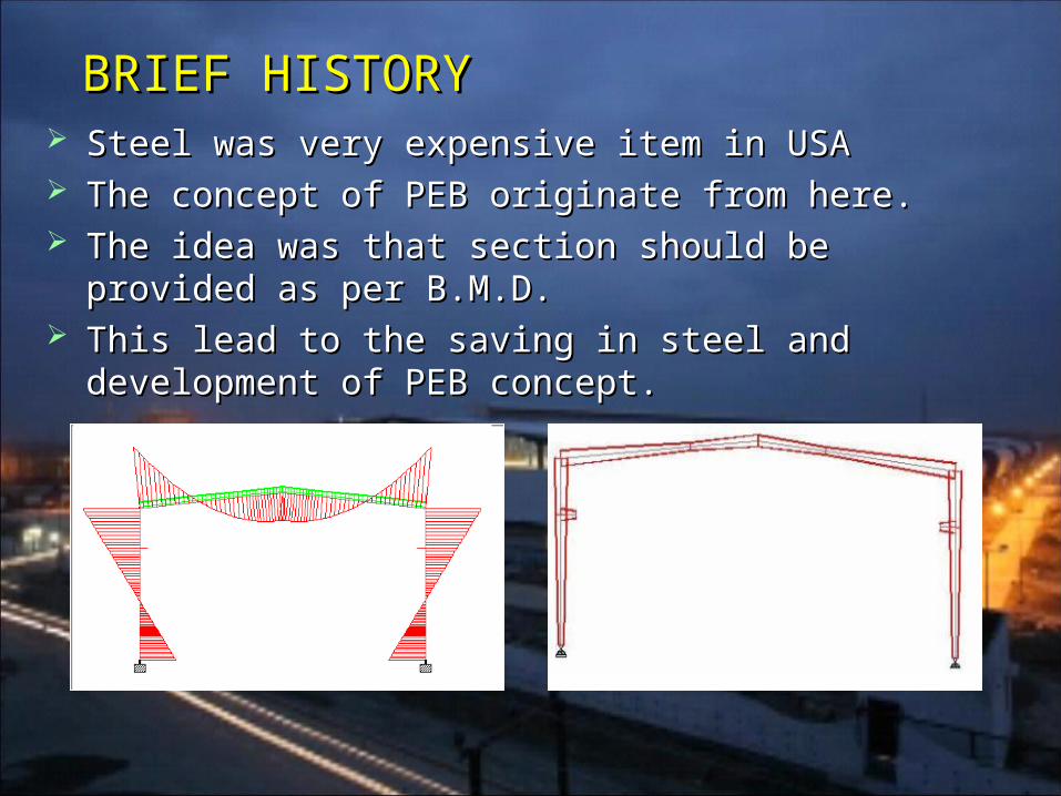
Steel was very expensive item in USASteel was very expensive item in USA The concept of PEB originate from here.The concept of PEB originate from here. The idea was that section should be provided as per The idea was that section should be provided as per
B.M.D.B.M.D. This lead to the saving in steel and development of This lead to the saving in steel and development of
PEB concept.PEB concept.
BRIEF HISTORYBRIEF HISTORY
APPLICATIONSAPPLICATIONS Industrial BuildingsIndustrial Buildings WarehousesWarehouses Commercial ComplexesCommercial Complexes ShowroomsShowrooms OfficesOffices SchoolsSchools Indoor StadiumsIndoor Stadiums Outdoor Stadiums with canopiesOutdoor Stadiums with canopies Gas StationsGas Stations Metro Stations, Bus Terminals, Parking LotsMetro Stations, Bus Terminals, Parking Lots Primary Health Centers, Angan wadi’sPrimary Health Centers, Angan wadi’s And many more…And many more…
P E BP E B
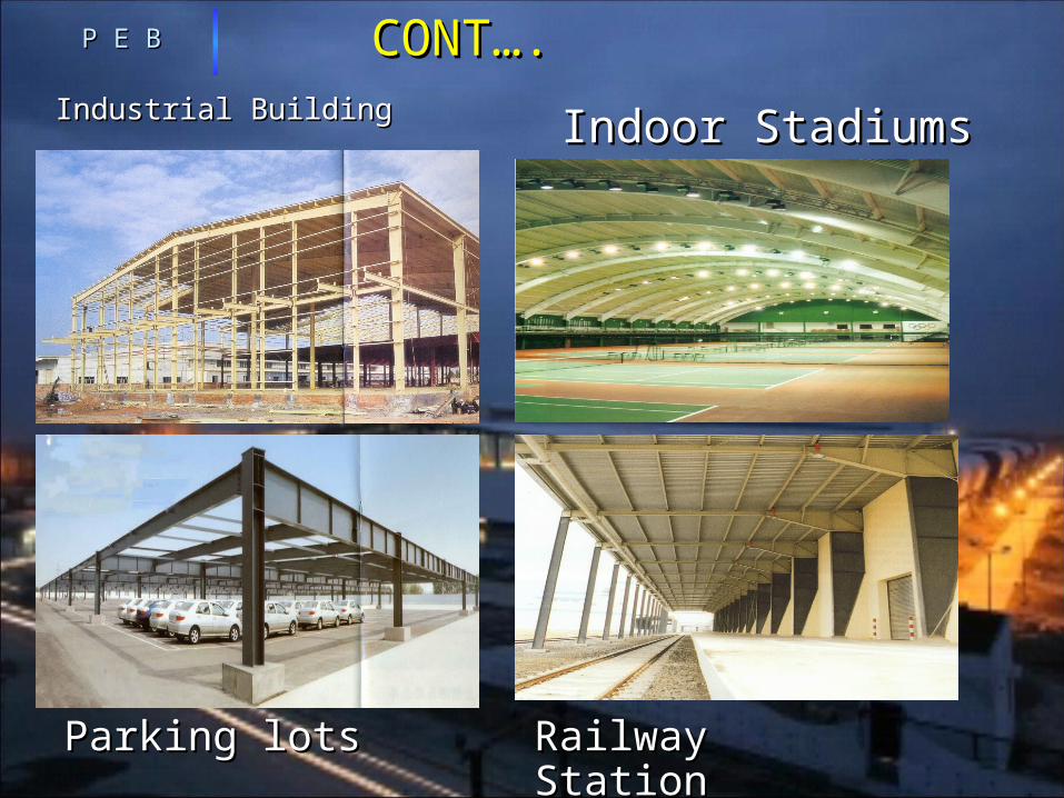
CONT….CONT….
Industrial BuildingIndustrial Building
P E BP E B
Parking lotsParking lots
Indoor StadiumsIndoor Stadiums
Railway StationRailway Station
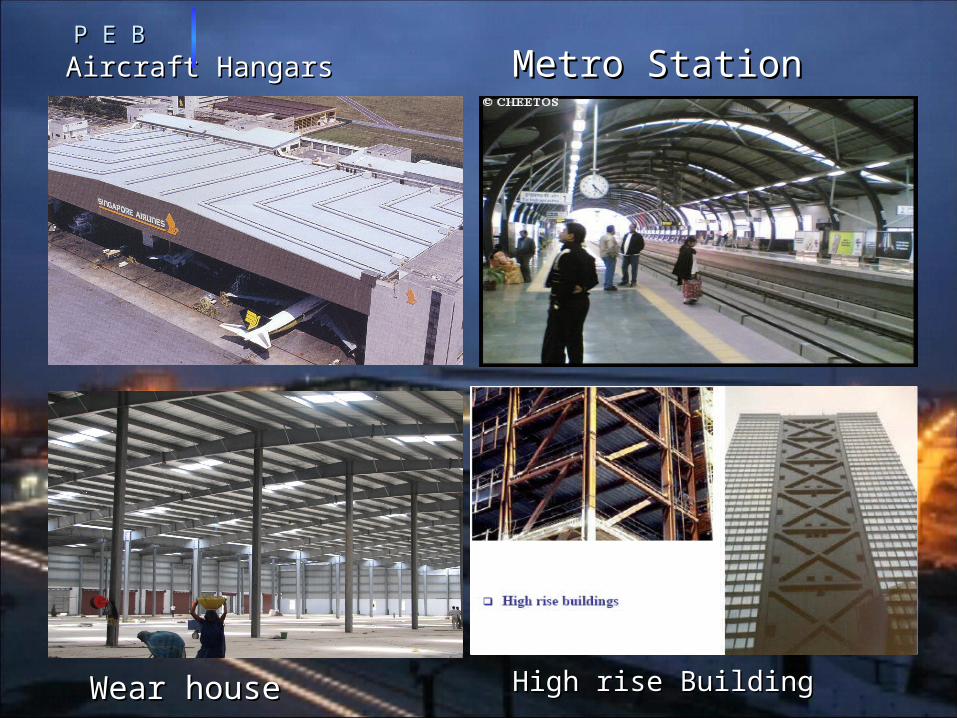
Aircraft HangarsAircraft HangarsP E BP E B
Metro StationMetro Station
Wear houseWear house High rise BuildingHigh rise Building
ADVANTAGESADVANTAGES
Aesthetic AppealAesthetic Appeal Faster CompletionFaster Completion EconomicalEconomical Seismic ResistanceSeismic Resistance Ease of ExpansionEase of Expansion Maintenance FreeMaintenance Free Large Clear SpansLarge Clear Spans Controlled QualityControlled Quality Hassle FreeHassle Free
P E BP E B
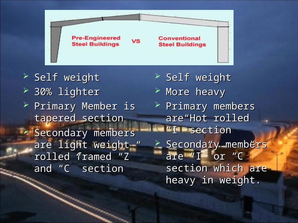
Self weight Self weight 30% lighter30% lighter Primary Member is Primary Member is
tapered sectiontapered section Secondary members Secondary members
are light weight rolled are light weight rolled framed “Z” and “C” framed “Z” and “C”
sectionsection
Self weightSelf weight More heavyMore heavy Primary members Primary members
are Hot rolled “I” are Hot rolled “I” sectionsection
Secondary Secondary members are “I” or members are “I” or “C” section which “C” section which are heavy in weight.are heavy in weight.
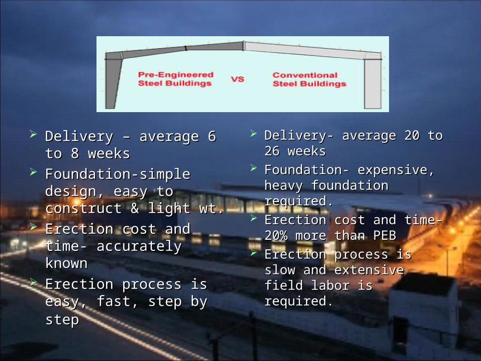
Delivery – average 6 Delivery – average 6 to 8 weeksto 8 weeks
Foundation-simple Foundation-simple design, easy to design, easy to construct & light wt.construct & light wt.
Erection cost and time- Erection cost and time- accurately knownaccurately known
Erection process is Erection process is easy, fast, step by easy, fast, step by stepstep
Delivery- average 20 Delivery- average 20 to 26 weeksto 26 weeks
Foundation- expensive, Foundation- expensive, heavy foundation heavy foundation required.required.
Erection cost and time- Erection cost and time- 20% more than PEB20% more than PEB
Erection process is Erection process is slow and extensive slow and extensive field labor is required.field labor is required.
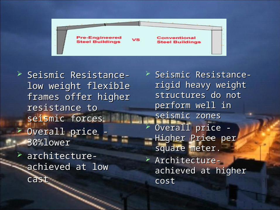
Seismic Resistance- Seismic Resistance- low weight flexible low weight flexible frames offer higher frames offer higher resistance to seismic resistance to seismic forcesforces
Overall price -Overall price -30%lower30%lower
architecture-achieved architecture-achieved at low castat low cast
Seismic Resistance- Seismic Resistance- rigid heavy weight rigid heavy weight structures do not structures do not perform well in perform well in seismic zonesseismic zones
Overall price - Higher Overall price - Higher Price per square Price per square meter.meter.
Architecture- achieved Architecture- achieved at higher costat higher cost
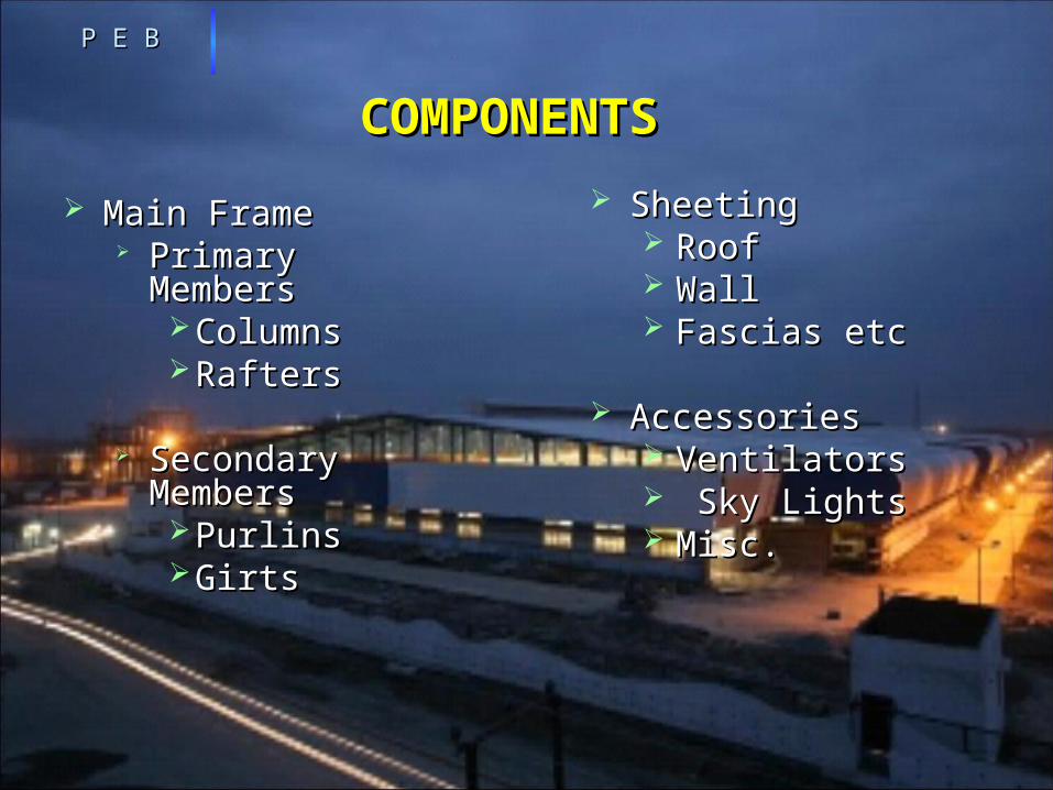
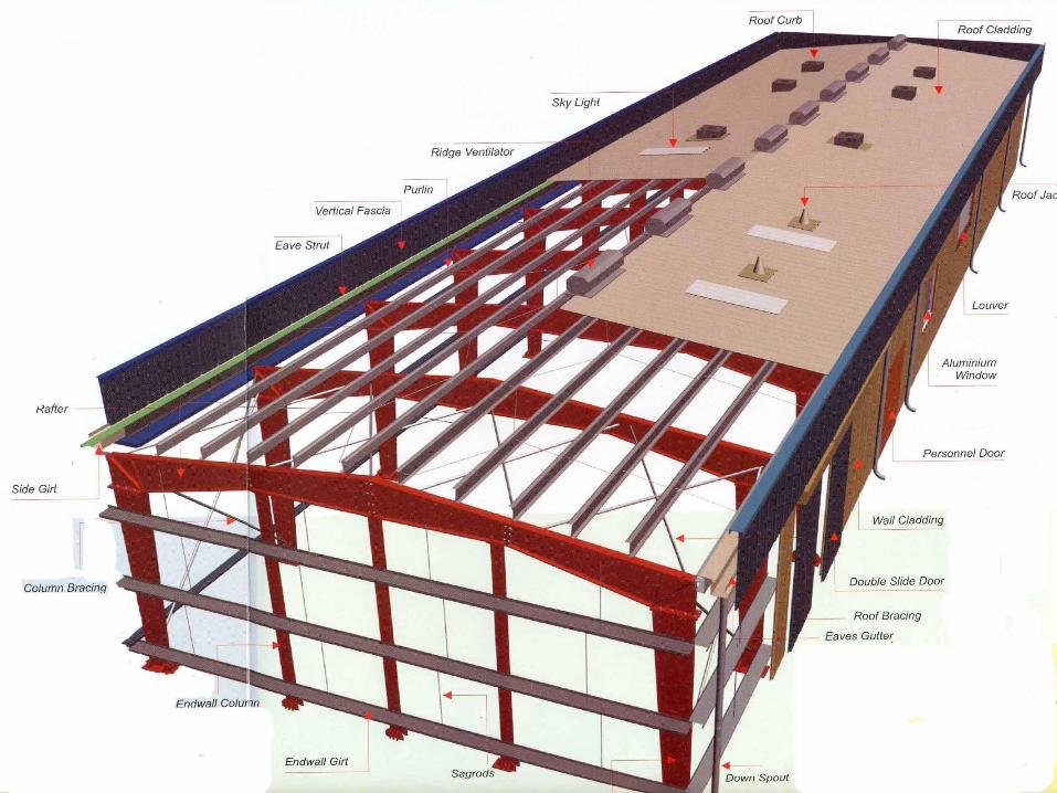
COMPONENTSCOMPONENTS
Main FrameMain Frame Primary Primary
MembersMembers ColumnsColumns RaftersRafters
Secondary Secondary MembersMembers PurlinsPurlins GirtsGirts
P E BP E B
SheetingSheeting RoofRoof WallWall Fascias etcFascias etc
AccessoriesAccessories VentilatorsVentilators Sky LightsSky Lights Misc.Misc.
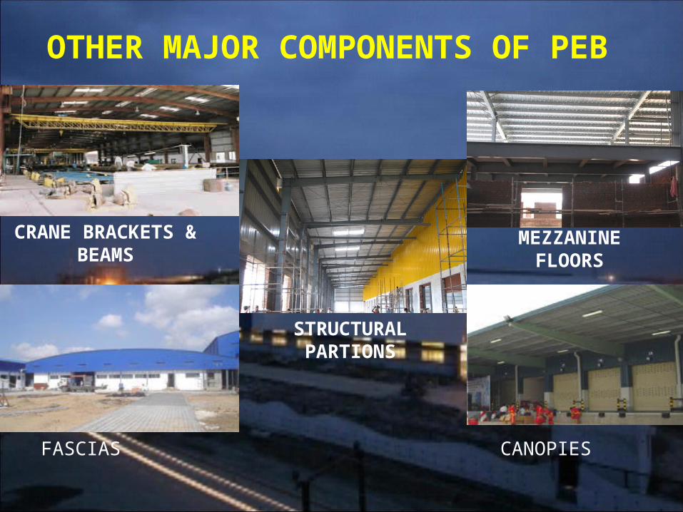
OTHER MAJOR COMPONENTS OF PEB
CRANE BRACKETS & BEAMS
MEZZANINE FLOORS
STRUCTURAL PARTIONS
FASCIAS CANOPIES
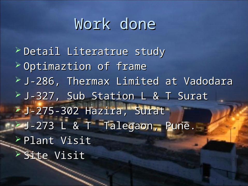
Work done Work done
Detail Detail Literatrue studyLiteratrue study Optimaztion of frameOptimaztion of frame J-286, Thermax Limited at VadodaraJ-286, Thermax Limited at Vadodara J-327, Sub Station L & T SuratJ-327, Sub Station L & T Surat J-275-302 Hazira, SuratJ-275-302 Hazira, Surat J-273 L & T Talegaon, Pune.J-273 L & T Talegaon, Pune. Plant VisitPlant Visit Site VisitSite Visit
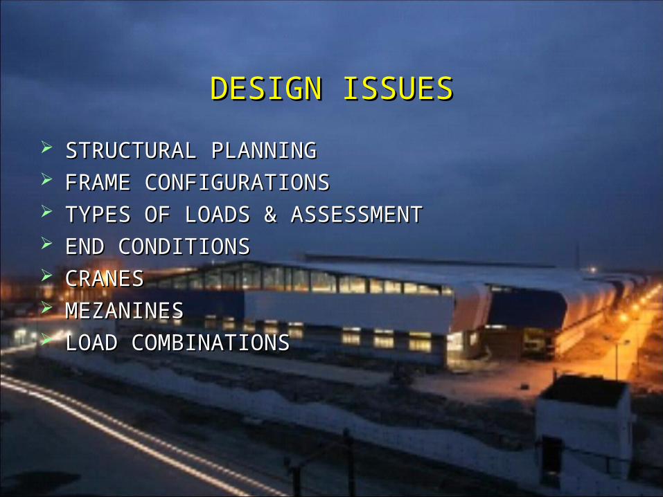
DESIGN ISSUESDESIGN ISSUES
STRUCTURAL PLANNINGSTRUCTURAL PLANNING FRAME CONFIGURATIONSFRAME CONFIGURATIONS TYPES OF LOADS & ASSESSMENTTYPES OF LOADS & ASSESSMENT END CONDITIONSEND CONDITIONS CRANESCRANES MEZANINESMEZANINES LOAD COMBINATIONSLOAD COMBINATIONS
Load 1X
YZ
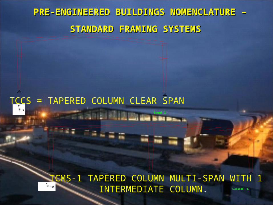
PRE-ENGINEERED BUILDINGS NOMENCLATURE PRE-ENGINEERED BUILDINGS NOMENCLATURE
– STANDARD FRAMING SYSTEMS– STANDARD FRAMING SYSTEMS
TCCS = TAPERED COLUMN CLEAR SPAN
Load 1X
YZ
TCMS-1 TAPERED COLUMN MULTI-SPAN WITH 1 INTERMEDIATE COLUMN.
Load 1X
YZ
SSCS = SINGLE SLOPE CLEAR SPAN.
Load 1X
YZ
SSMS-1= SINGLE SLOPE MULTI-SPAN WITH 1 INTERMEDIATE COLUMN
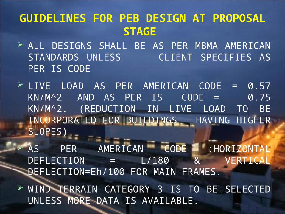
GUIDELINES FOR PEB DESIGN AT PROPOSAL STAGE
ALL DESIGNS SHALL BE AS PER MBMA AMERICAN STANDARDS UNLESS CLIENT SPECIFIES AS PER IS CODE
LIVE LOAD AS PER AMERICAN CODE = 0.57 KN/M^2 AND AS PER IS CODE = 0.75 KN/M^2. (REDUCTION IN LIVE LOAD TO BE INCORPORATED FOR BUILDINGS HAVING HIGHER SLOPES)
AS PER AMERICAN CODE :HORIZONTAL DEFLECTION = L/180 & VERTICAL DEFLECTION=Eh/100 FOR MAIN FRAMES.
WIND TERRAIN CATEGORY 3 IS TO BE SELECTED UNLESS MORE DATA IS AVAILABLE.
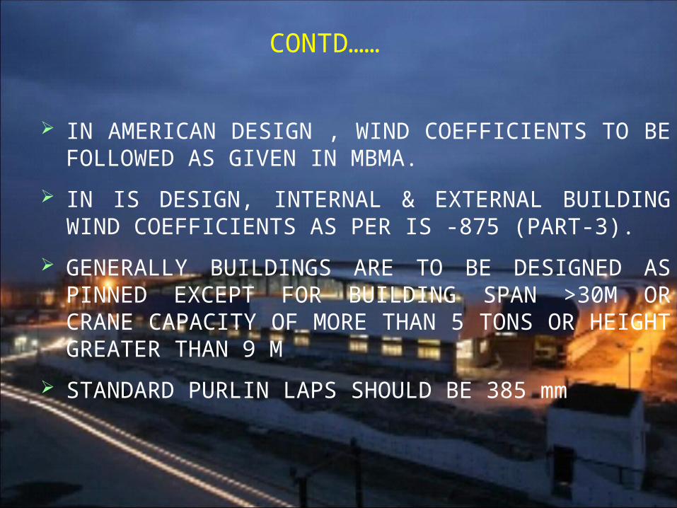
CONTD……
IN AMERICAN DESIGN , WIND COEFFICIENTS TO BE FOLLOWED AS GIVEN IN MBMA.
IN IS DESIGN, INTERNAL & EXTERNAL BUILDING WIND COEFFICIENTS AS PER IS -875 (PART-3).
GENERALLY BUILDINGS ARE TO BE DESIGNED AS PINNED EXCEPT FOR BUILDING SPAN >30M OR CRANE CAPACITY OF MORE THAN 5 TONS OR HEIGHT GREATER THAN 9 M
STANDARD PURLIN LAPS SHOULD BE 385 mm
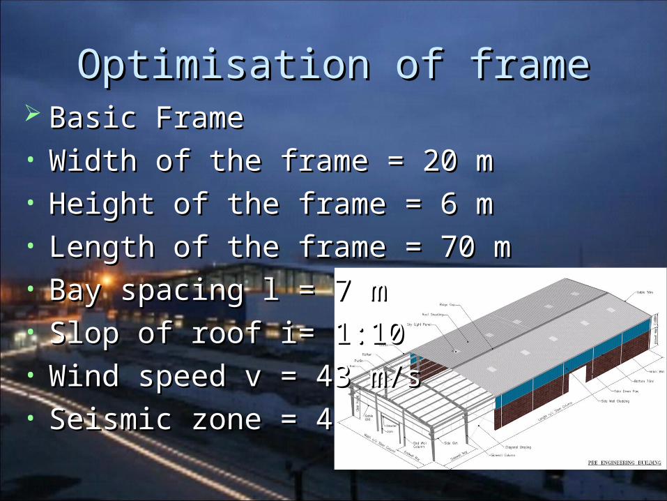
Optimisation of frameOptimisation of frame Basic FrameBasic Frame• Width of the frame = 20 mWidth of the frame = 20 m• Height of the frame = 6 mHeight of the frame = 6 m• Length of the frame = 70 mLength of the frame = 70 m• Bay spacing l = 7 mBay spacing l = 7 m• Slop of roof i= 1:10Slop of roof i= 1:10• Wind speed v = 43 m/sWind speed v = 43 m/s• Seismic zone = 4Seismic zone = 4
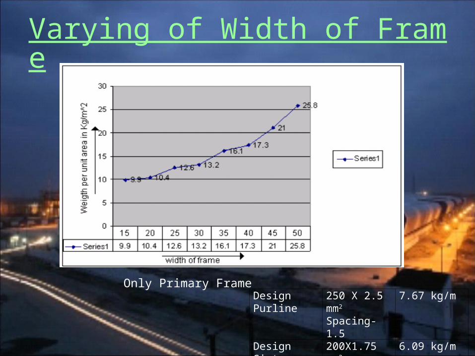
Varying of Width of Frame
Only Primary Frame Design Purline 250 X 2.5 mm2
Spacing-1.57.67 kg/m
Design Girt 200X1.75 mm2
Spacing-1.5
6.09 kg/m
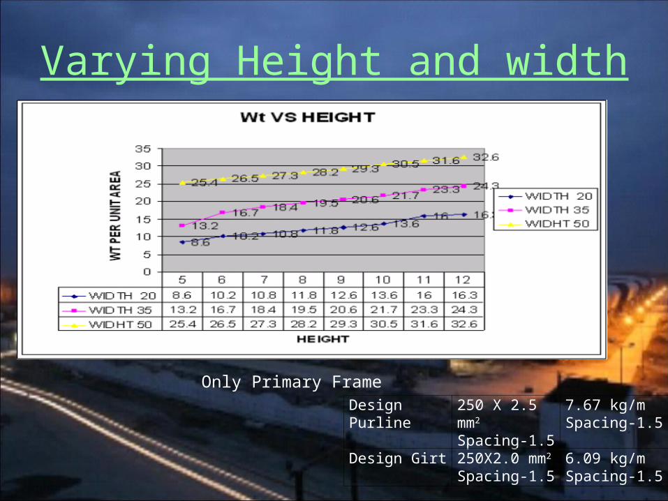
Varying Height and width
Design Purline 250 X 2.5 mm2
Spacing-1.57.67 kg/mSpacing-1.5
Design Girt 250X2.0 mm2
Spacing-1.56.09 kg/mSpacing-1.5
Only Primary Frame
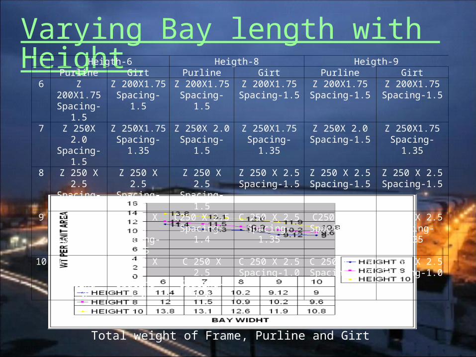
Varying Bay length with Height Heigth-6 Heigth-8 Heigth-9
Purline Girt Purline Girt Purline Girt6 Z 200X1.75
Spacing-1.5Z 200X1.75Spacing-1.5
Z 200X1.75Spacing-1.5
Z 200X1.75Spacing-1.5
Z 200X1.75Spacing-1.5
Z 200X1.75Spacing-1.5
7 Z 250X 2.0Spacing-1.5
Z 250X1.75Spacing-1.35
Z 250X 2.0Spacing-1.5
Z 250X1.75Spacing-1.35
Z 250X 2.0Spacing-1.5
Z 250X1.75Spacing-1.35
8 Z 250 X 2.5Spacing-1.5
Z 250 X 2.5Spacing-1.5
Z 250 X 2.5Spacing-1.5
Z 250 X 2.5Spacing-1.5
Z 250 X 2.5Spacing-1.5
Z 250 X 2.5Spacing-1.5
9 C250 X 2.5Spacing-1.4
C 250 X 2.5Spacing-1.35
C250 X 2.5Spacing-1.4
C 250 X 2.5Spacing-1.35
C250 X 2.5Spacing-1.4
C 250 X 2.5Spacing-1.35
10 C 250 X 2.5Spacing-1.0
C 250 X 2.5Spacing-1.0
C 250 X 2.5Spacing-1.0
C 250 X 2.5Spacing-1.0
C 250 X 2.5Spacing-1.0
C 250 X 2.5Spacing-1.0
Total weight of Frame, Purline and Girt
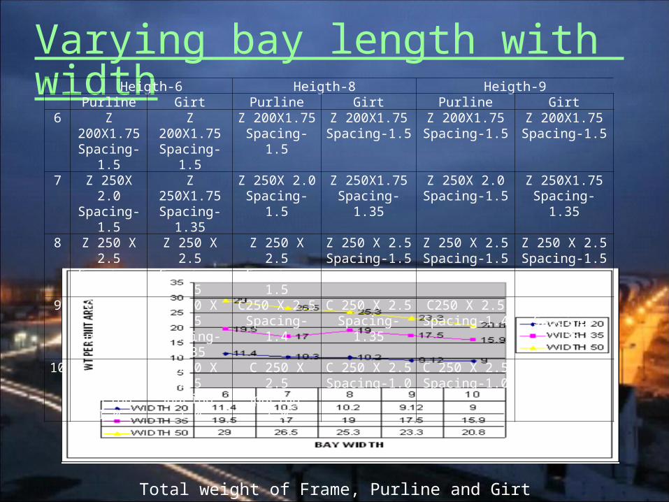
Varying bay length with widthHeigth-6 Heigth-8 Heigth-9
Purline Girt Purline Girt Purline Girt6 Z 200X1.75
Spacing-1.5Z 200X1.75Spacing-1.5
Z 200X1.75Spacing-1.5
Z 200X1.75Spacing-1.5
Z 200X1.75Spacing-1.5
Z 200X1.75Spacing-1.5
7 Z 250X 2.0Spacing-1.5
Z 250X1.75Spacing-1.35
Z 250X 2.0Spacing-1.5
Z 250X1.75Spacing-1.35
Z 250X 2.0Spacing-1.5
Z 250X1.75Spacing-1.35
8 Z 250 X 2.5Spacing-1.5
Z 250 X 2.5Spacing-1.5
Z 250 X 2.5Spacing-1.5
Z 250 X 2.5Spacing-1.5
Z 250 X 2.5Spacing-1.5
Z 250 X 2.5Spacing-1.5
9 C250 X 2.5Spacing-1.4
C 250 X 2.5Spacing-1.35
C250 X 2.5Spacing-1.4
C 250 X 2.5Spacing-1.35
C250 X 2.5Spacing-1.4
C 250 X 2.5Spacing-1.35
10 C 250 X 2.5Spacing-1.0
C 250 X 2.5Spacing-1.0
C 250 X 2.5Spacing-1.0
C 250 X 2.5Spacing-1.0
C 250 X 2.5Spacing-1.0
C 250 X 2.5Spacing-1.0
Total weight of Frame, Purline and Girt
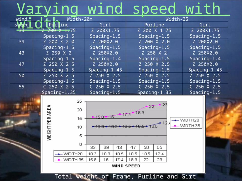
Varying wind speed with width wind Width-20m Width-35speed Purline Girt Purline Girt
33 Z 200 X 1.75Spacing-1.5
Z 200X1.75Spacing-1.5
Z 200 X 1.75Spacing-1.5
Z 200X1.75Spacing-1.5
39 Z 200 X 2.0Spacing-1.5
Z 200X2.0Spacing-1.5
Z 200 X 2.0Spacing-1.5
Z 200X2.0Spacing-1.5
43 Z 250 X 2Spacing-1.5
Z 250X2.0Spacing-1.4
Z 250 X 2Spacing-1.5
Z 250X2.0Spacing-1.4
47 Z 250 X 2.5Spacing-1.5
Z 250X2.0Spacing-1.45
Z 250 X 2.5Spacing-1.5
Z 250X2.0Spacing-1.45
50 Z 250 X 2.5Spacing-1.5
Z 250 X 2.5Spacing-1.5
Z 250 X 2.5Spacing-1.5
Z 250 X 2.5Spacing-1.5
55 C 250 X 2.5Spacing-1.35
C 250 X 2.5Spacing-1.5
C 250 X 2.5Spacing-1.35
C 250 X 2.5Spacing-1.5
Total weight of Frame, Purline and Girt
Steps of DesignSteps of Design Wind load calculationWind load calculation Purline DesignPurline Design Girt DesignGirt Design Design of Main FrameDesign of Main Frame Base PlateBase Plate Anchor Bolt design for Moment ConditionAnchor Bolt design for Moment Condition Anchor Bolt design for Shear ConditionAnchor Bolt design for Shear Condition Gable column designGable column design Design of connection plateDesign of connection plate Cranes DesignCranes Design
J-268 Thermax LimitedJ-268 Thermax Limited
VadodaraVadodara
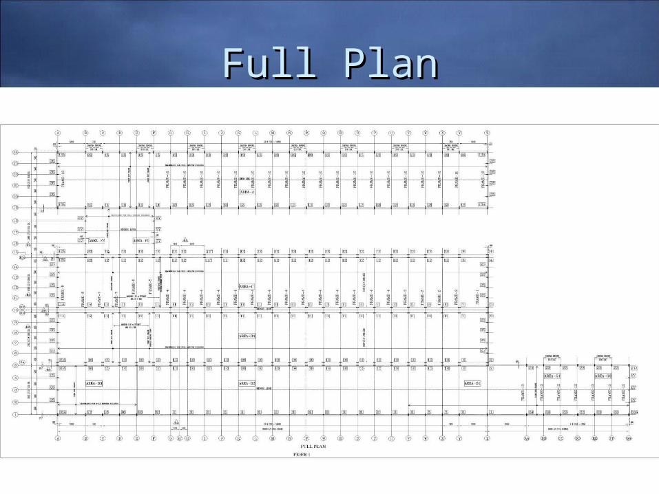
Full PlanFull Plan
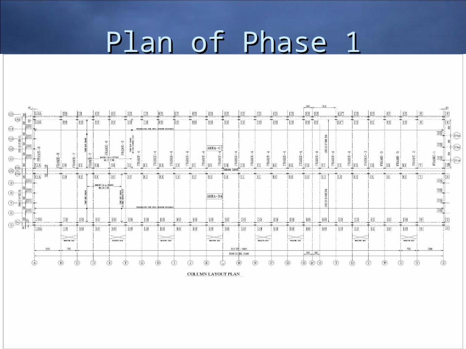
Plan of Phase 1Plan of Phase 1
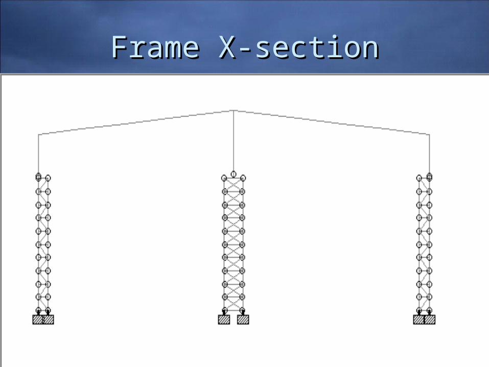
Frame X-sectionFrame X-section
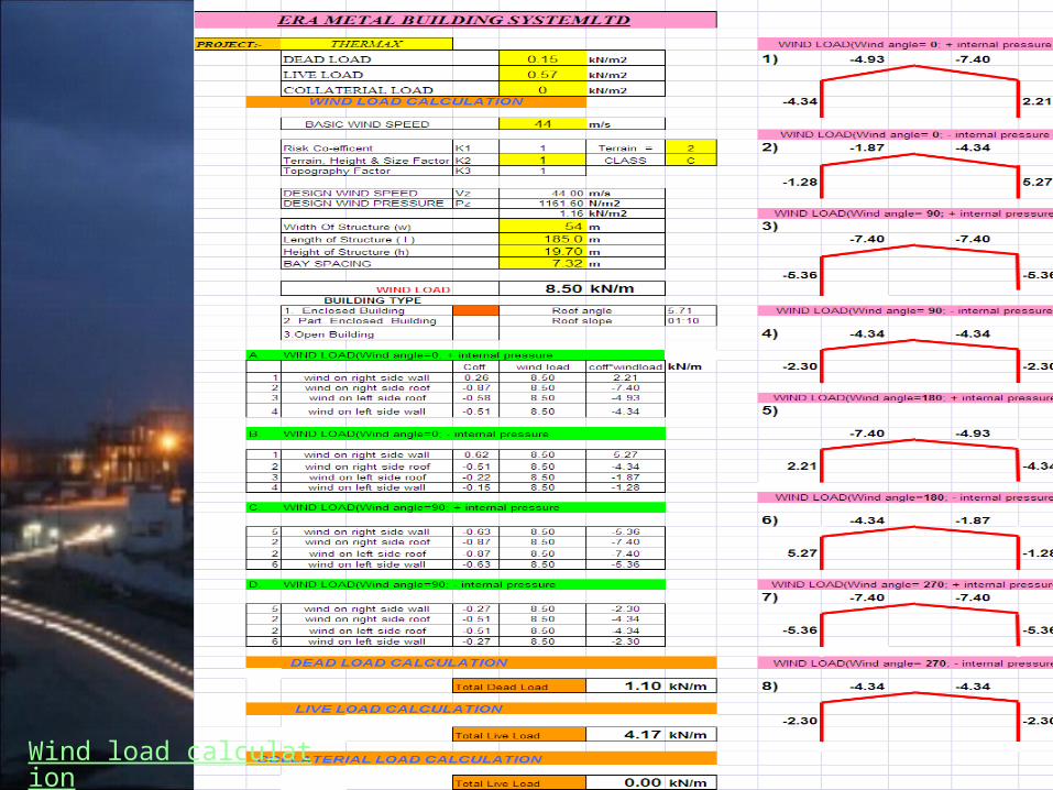
Wind load calculation
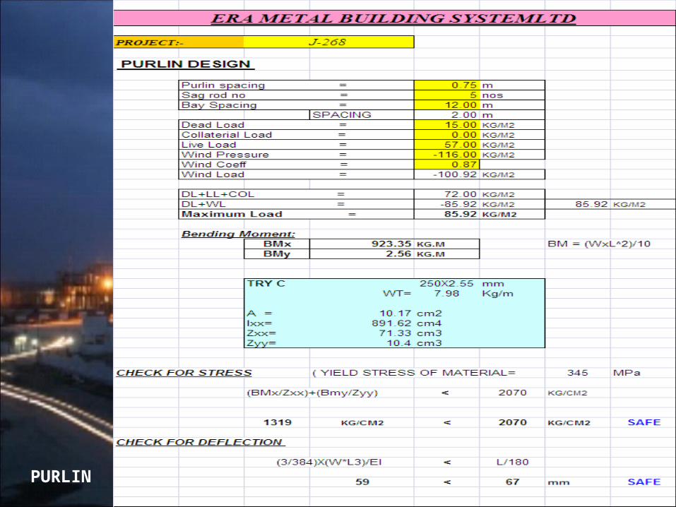
PURLIN
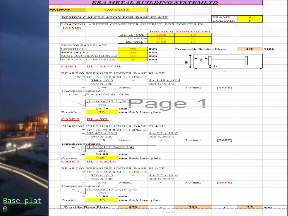
Base plate

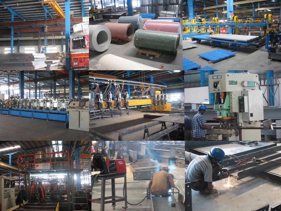
Plant visit at
Pant Nagar
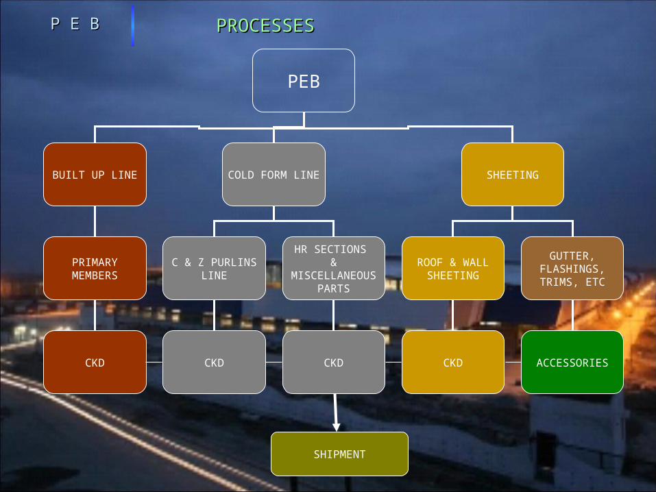
PROCESSESPROCESSES
PEB
BUILT UP LINE COLD FORM LINE SHEETING
PRIMARY MEMBERS
CKD
C & Z PURLINS LINE
HR SECTIONS &
MISCELLANEOUS PARTS
ROOF & WALL SHEETING
GUTTER, FLASHINGS, TRIMS, ETC
CKD CKD CKD ACCESSORIES
SHIPMENT
P E BP E B
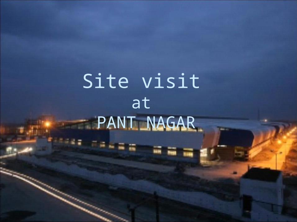
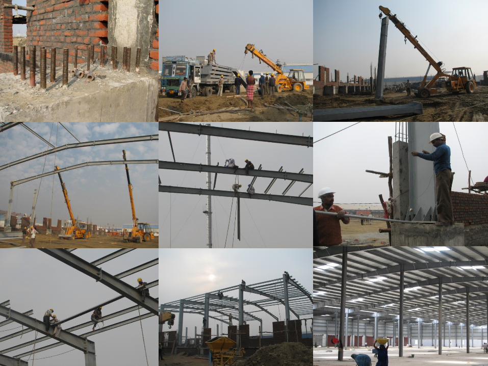
Site visit at
PANT NAGAR
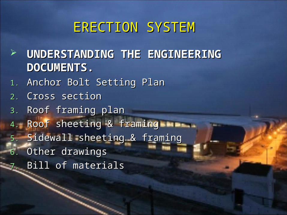
ERECTION SYSTEMERECTION SYSTEM
UNDERSTANDING THE UNDERSTANDING THE ENGINEERING DOCUMENTS.ENGINEERING DOCUMENTS.
1.1. Anchor Bolt Setting PlanAnchor Bolt Setting Plan
2.2. Cross sectionCross section
3.3. Roof framing planRoof framing plan
4.4. Roof sheeting & framingRoof sheeting & framing
5.5. Sidewall sheeting & framingSidewall sheeting & framing
6.6. Other drawingsOther drawings
7.7. Bill of materialsBill of materials
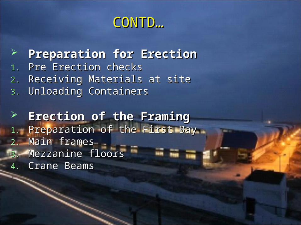
CONTD…CONTD…
Preparation for ErectionPreparation for Erection1.1. Pre Erection checksPre Erection checks2.2. Receiving Materials at siteReceiving Materials at site3.3. Unloading ContainersUnloading Containers
Erection of the FramingErection of the Framing1.1. Preparation of the First BayPreparation of the First Bay2.2. Main framesMain frames3.3. Mezzanine floorsMezzanine floors4.4. Crane BeamsCrane Beams
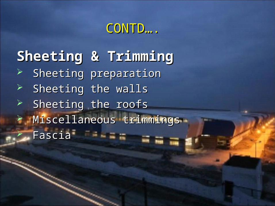
CONTD….CONTD….
Sheeting & TrimmingSheeting & Trimming Sheeting preparationSheeting preparation Sheeting the wallsSheeting the walls Sheeting the roofsSheeting the roofs Miscellaneous trimmingsMiscellaneous trimmings FasciaFascia

Recommended