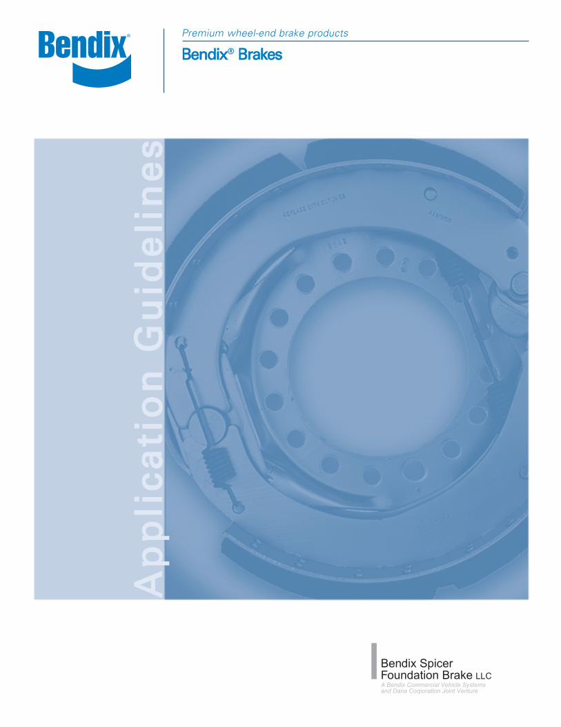
BBeennddiixx®® BBrraakkeessPremium wheel-end brake products
AApp
ppllii
ccaattii
oonn
GGuu
iiddee
lliinn
eess
1
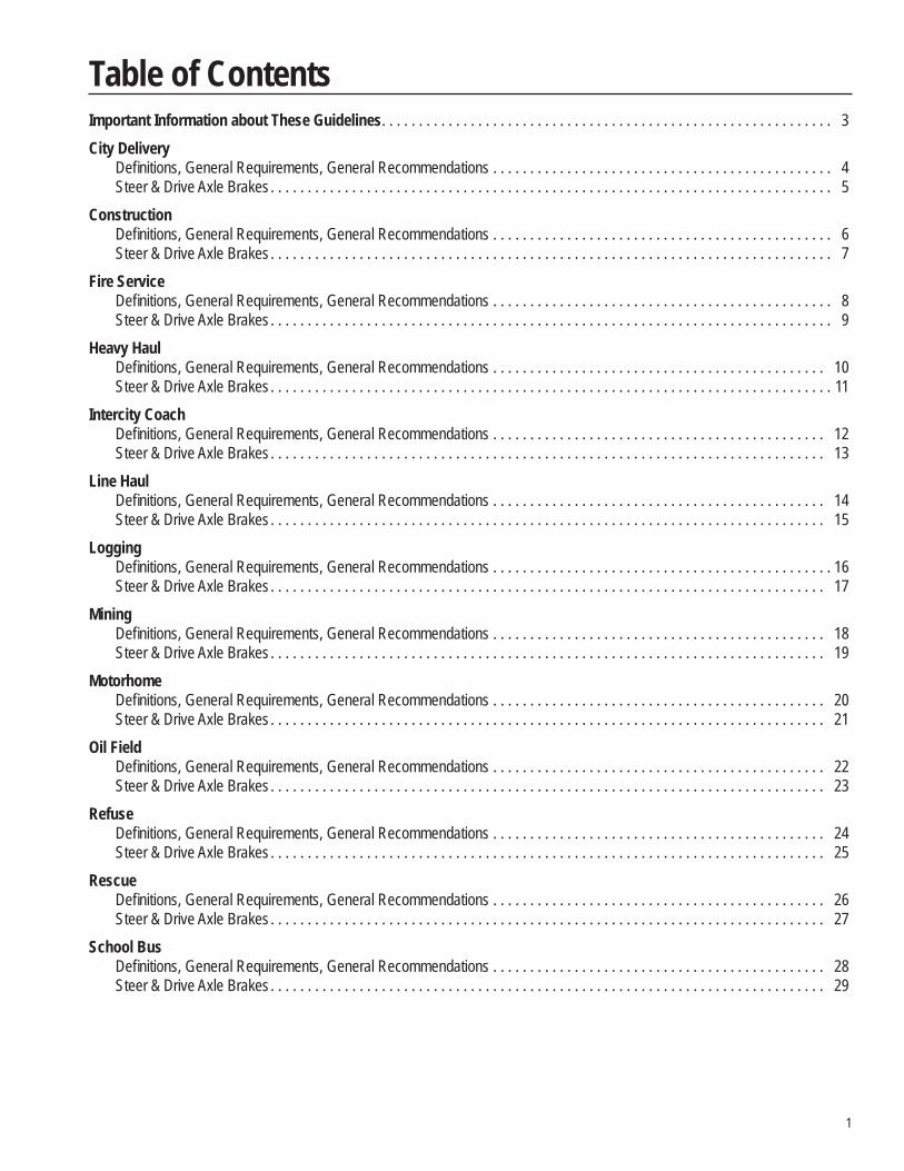
Important Information about These Guidelines. . . . . . . . . . . . . . . . . . . . . . . . . . . . . . . . . . . . . . . . . . . . . . . . . . . . . . . . . . . . . 3City Delivery
Defi nitions, General Requirements, General Recommendations . . . . . . . . . . . . . . . . . . . . . . . . . . . . . . . . . . . . . . . . . . . . . . 4Steer & Drive Axle Brakes . . . . . . . . . . . . . . . . . . . . . . . . . . . . . . . . . . . . . . . . . . . . . . . . . . . . . . . . . . . . . . . . . . . . . . . . . . . . 5
Construction Defi nitions, General Requirements, General Recommendations . . . . . . . . . . . . . . . . . . . . . . . . . . . . . . . . . . . . . . . . . . . . . . 6Steer & Drive Axle Brakes . . . . . . . . . . . . . . . . . . . . . . . . . . . . . . . . . . . . . . . . . . . . . . . . . . . . . . . . . . . . . . . . . . . . . . . . . . . . 7
Fire Service Defi nitions, General Requirements, General Recommendations . . . . . . . . . . . . . . . . . . . . . . . . . . . . . . . . . . . . . . . . . . . . . . 8Steer & Drive Axle Brakes . . . . . . . . . . . . . . . . . . . . . . . . . . . . . . . . . . . . . . . . . . . . . . . . . . . . . . . . . . . . . . . . . . . . . . . . . . . . 9
Heavy HaulDefi nitions, General Requirements, General Recommendations . . . . . . . . . . . . . . . . . . . . . . . . . . . . . . . . . . . . . . . . . . . . . 10Steer & Drive Axle Brakes . . . . . . . . . . . . . . . . . . . . . . . . . . . . . . . . . . . . . . . . . . . . . . . . . . . . . . . . . . . . . . . . . . . . . . . . . . . . 11
Intercity Coach Defi nitions, General Requirements, General Recommendations . . . . . . . . . . . . . . . . . . . . . . . . . . . . . . . . . . . . . . . . . . . . . 12Steer & Drive Axle Brakes . . . . . . . . . . . . . . . . . . . . . . . . . . . . . . . . . . . . . . . . . . . . . . . . . . . . . . . . . . . . . . . . . . . . . . . . . . . 13
Line HaulDefi nitions, General Requirements, General Recommendations . . . . . . . . . . . . . . . . . . . . . . . . . . . . . . . . . . . . . . . . . . . . . 14Steer & Drive Axle Brakes . . . . . . . . . . . . . . . . . . . . . . . . . . . . . . . . . . . . . . . . . . . . . . . . . . . . . . . . . . . . . . . . . . . . . . . . . . . 15
LoggingDefi nitions, General Requirements, General Recommendations . . . . . . . . . . . . . . . . . . . . . . . . . . . . . . . . . . . . . . . . . . . . . . 16Steer & Drive Axle Brakes . . . . . . . . . . . . . . . . . . . . . . . . . . . . . . . . . . . . . . . . . . . . . . . . . . . . . . . . . . . . . . . . . . . . . . . . . . . 17
MiningDefi nitions, General Requirements, General Recommendations . . . . . . . . . . . . . . . . . . . . . . . . . . . . . . . . . . . . . . . . . . . . . 18Steer & Drive Axle Brakes . . . . . . . . . . . . . . . . . . . . . . . . . . . . . . . . . . . . . . . . . . . . . . . . . . . . . . . . . . . . . . . . . . . . . . . . . . . 19
Motorhome Defi nitions, General Requirements, General Recommendations . . . . . . . . . . . . . . . . . . . . . . . . . . . . . . . . . . . . . . . . . . . . . 20Steer & Drive Axle Brakes . . . . . . . . . . . . . . . . . . . . . . . . . . . . . . . . . . . . . . . . . . . . . . . . . . . . . . . . . . . . . . . . . . . . . . . . . . . 21
Oil FieldDefi nitions, General Requirements, General Recommendations . . . . . . . . . . . . . . . . . . . . . . . . . . . . . . . . . . . . . . . . . . . . . 22Steer & Drive Axle Brakes . . . . . . . . . . . . . . . . . . . . . . . . . . . . . . . . . . . . . . . . . . . . . . . . . . . . . . . . . . . . . . . . . . . . . . . . . . . 23
RefuseDefi nitions, General Requirements, General Recommendations . . . . . . . . . . . . . . . . . . . . . . . . . . . . . . . . . . . . . . . . . . . . . 24Steer & Drive Axle Brakes . . . . . . . . . . . . . . . . . . . . . . . . . . . . . . . . . . . . . . . . . . . . . . . . . . . . . . . . . . . . . . . . . . . . . . . . . . . 25
RescueDefi nitions, General Requirements, General Recommendations . . . . . . . . . . . . . . . . . . . . . . . . . . . . . . . . . . . . . . . . . . . . . 26Steer & Drive Axle Brakes . . . . . . . . . . . . . . . . . . . . . . . . . . . . . . . . . . . . . . . . . . . . . . . . . . . . . . . . . . . . . . . . . . . . . . . . . . . 27
School BusDefi nitions, General Requirements, General Recommendations . . . . . . . . . . . . . . . . . . . . . . . . . . . . . . . . . . . . . . . . . . . . . 28Steer & Drive Axle Brakes . . . . . . . . . . . . . . . . . . . . . . . . . . . . . . . . . . . . . . . . . . . . . . . . . . . . . . . . . . . . . . . . . . . . . . . . . . . 29
Table of Contents
2
Transit CoachDefi nitions, General Requirements, General Recommendations . . . . . . . . . . . . . . . . . . . . . . . . . . . . . . . . . . . . . . . . . . . . . 30Steer & Drive Axle Brakes . . . . . . . . . . . . . . . . . . . . . . . . . . . . . . . . . . . . . . . . . . . . . . . . . . . . . . . . . . . . . . . . . . . . . . . . . . . 31
Nomenclature . . . . . . . . . . . . . . . . . . . . . . . . . . . . . . . . . . . . . . . . . . . . . . . . . . . . . . . . . . . . . . . . . . . . . . . . . . . . . . . . . . . . . . . 32
Table of Contents
3
Purpose The purpose of these Brake Application Guidelines is to provide original equipment manufacturer (OEM) builders of medium and heavy duty trucks with information about which Bendix Spicer Foundation Brake products are approved by Bendix Spicer Foundation Brake for use in common vocational applications in the USA and Canada.
Use of Guidelines These Guidelines apply to the specifi c on, on-off, and off highway vocational categories and axle applications which are listed, for vehicles operated in the USA and Canada. The categories equate to the commodity and service categories used by OEM truck builders. Within each category, Bendix Spicer Foundation Brake has approved the steer axle brake and drive axle brake applications shown in the table (subject to any applicable notes), provided that the vehicle falls within the “Defi nitions” and “Typical Vehicle Types” and meets the “General Requirements” set out for that category. Brake approval is based on gross axle weight rating (GAWR), static loaded radius of tire (SLR), air chamber size, brake adjuster length (S-cam brake only), and the brake lining material.These Guidelines do not apply to the use of Bendix Spicer Foundation Brake products in vehicles operated outside the USA and Canada, in vocational categories or axle applications other than those specifi ed herein, for duty cycles or ratings other than those listed herein, for vehicles with fi xed liftable auxiliary axles (tag or pusher) or for any off-road applications. Approval for such uses may be requested on an individual basis by submitting a Brake Application Approval Request Form to the Bendix Spicer Foundation Brake Application Engineering Department at the address below.
Brake Warranties Bendix Spicer Foundation Brake warranties for steer axle, drive axle and trailer brakes are set out in the Bendix Spicer Foundation Brake Applications and Installations (BW7216) must either meet the requirements of these Guidelines for automatic approval or be approved by the Bendix Spicer Foundation Brake Application Engineering Department. Failure to obtain application approval or the use of Bendix Spicer Foundation Brakes or their components in non-approved applications will void the Bendix Spicer Foundation Brake warranty coverage. Modifi cation of the vehicle or brake confi guration, changes in the vocational use, or service outside the limits of these Guidelines may void the Bendix Spicer Foundation Brake warranty coverage.
Questions For answers to questions concerning these Guidelines or to request a Brake Application Approval Request Form for a use not covered by these Guidelines, contact one of the following:
Bendix Spicer Foundation Brake LLC Roadranger™ Sales and Service Offi ce866-610-9709 800-826-HELP (826-4357)www.foundationbrakes.com 24 hours a day in the USA and Canada
Changes to Guidelines These Guidelines are subject to change at any time, without prior notice, at the discretion of Bendix Spicer Foundation Brake LLC.For updates visit www.foundationbrakes.com
Effective Date: [October 2007]
Important Information about These Guidelines
4
Defi nitions Pickup and delivery service within cities and/or suburban areas Operation on road surfaces of concrete, asphalt and maintained gravel Three (3) miles between starts/stops (typical) 100% load going/40% load return (typical)
Typical Vehicle Types Auto Transport Truck Moving Van Pickup and Delivery Tanker TruckBeverage Truck Municipal Truck Refrigerated TruckFlatbed Truck Newspaper Delivery Stake Truck
General Requirements• Cam same operation for all steerable axle brakes • Air chamber bracket assembly gusset and additional camshaft bracket support see page 45, attached to the axle housing
when the: a. Brake centerline to air chamber centerline distance (BCCC dimension) is greater than 343 mm [13.5"] b. Application use type 30/36 or 36/36 Spring brake chambers. c. Super Single Tire (Wide Base Tires) Note: The above support can be supplied by BSFB or the vehicle manufacturer but must be approved by BSFB
Application Engineering Department.• Air chamber bracket with gusset, see page 45, when the application includes any of the following components:
a. Super single tire b. Type 30/36 or 36/36 Spring brake chambers c. High-articulation mechanical suspensions d. Two-speed axle or Planetary double reduction axles
• Applications for use in countries other than the USA and Canada must be reviewed by BSFB Application Engineering. • Vehicle manufacturer is responsible for air system design, parking and stopping distance performance. • For all S-cam brake models the camshaft input torque is limited to 2545 N•m [22,500 in-lbs]. • Applications on vehicles with fi xed or liftable auxiliary axles (tag or pusher) must be approved on an individual basis by the
BSFB Application Engineering Department, as auxiliary axles may impact the braking performance of the vehicle.
General Recommendations• Cam same for all brake assemblies • Dust shields for all applications • Use Auxiliary retarders per TMC RP636 • Brake drum / Rotor material specifi cation per SAE J431. Drum / rotor surface fi nish 4.57 micrometers [180 max microinch]
and .38 mm [.015”] runout when mounted on a hub rotated on bearings. See notes section for Minimum Drum Weight requirements
• Brake air system balance per TMC RP632 • Due to legal maximum highway GAWR (17,000-20,000 lb.) per code of federal regulations, 23 CFR - chapter 1, part 658
and brake balance to trailers, brakes should be rated to 20,000 when used on structurally rated 23,000 GAWR drive axles.
City Delivery
5
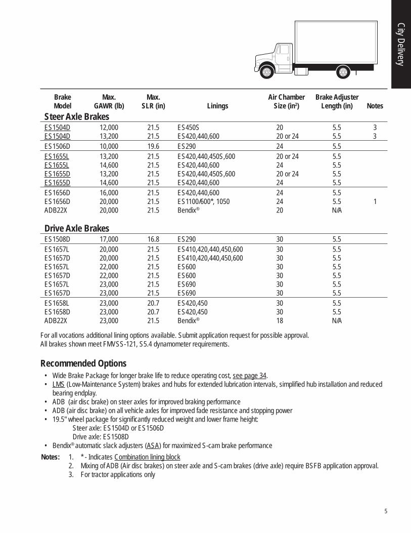
For all vocations additional lining options available. Submit application request for possible approval.All brakes shown meet FMVSS-121, S5.4 dynamometer requirements.
Recommended Options• Wide Brake Package for longer brake life to reduce operating cost, see page 34.• LMS (Low-Maintenance System) brakes and hubs for extended lubrication intervals, simplifi ed hub installation and reduced
bearing endplay. • ADB (air disc brake) on steer axles for improved braking performance • ADB (air disc brake) on all vehicle axles for improved fade resistance and stopping power • 19.5" wheel package for signifi cantly reduced weight and lower frame height:
Steer axle: ES1504D or ES1506DDrive axle: ES1508D
• Bendix® automatic slack adjusters (ASA) for maximized S-cam brake performanceNotes: 1. * - Indicates Combination lining block 2. Mixing of ADB (Air disc brakes) on steer axle and S-cam brakes (drive axle) require BSFB application approval. 3. For tractor applications only
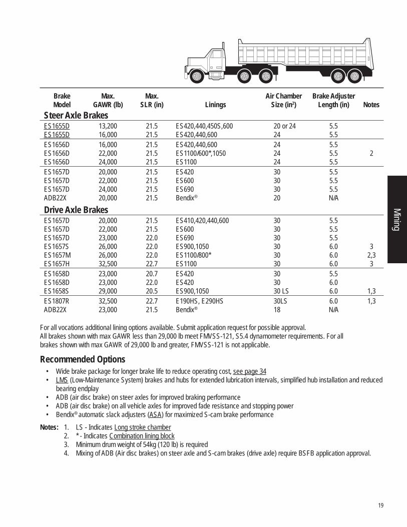
Brake Max. Max. Air Chamber Brake Adjuster Model GAWR (lb) SLR (in) Linings Size (in2) Length (in) NotesSteer Axle Brakes
ES1504D 12,000 21.5 ES450S 20 5.5 3 ES1504D 13,200 21.5 ES420,440,600 20 or 24 5.5 3 ES1506D 10,000 19.6 ES290 24 5.5 ES1655L 13,200 21.5 ES420,440,450S,600 20 or 24 5.5 ES1655L 14,600 21.5 ES420,440,600 24 5.5 ES1655D 13,200 21.5 ES420,440,450S,600 20 or 24 5.5 ES1655D 14,600 21.5 ES420,440,600 24 5.5 ES1656D 16,000 21.5 ES420,440,600 24 5.5 ES1656D 20,000 21.5 ES1100/600*, 1050 24 5.5 1 ADB22X 20,000 21.5 Bendix® 20 N/A
Drive Axle Brakes ES1508D 17,000 16.8 ES290 30 5.5 ES1657L 20,000 21.5 ES410,420,440,450,600 30 5.5 ES1657D 20,000 21.5 ES410,420,440,450,600 30 5.5 ES1657L 22,000 21.5 ES600 30 5.5 ES1657D 22,000 21.5 ES600 30 5.5 ES1657L 23,000 21.5 ES690 30 5.5 ES1657D 23,000 21.5 ES690 30 5.5 ES1658L 23,000 20.7 ES420,450 30 5.5 ES1658D 23,000 20.7 ES420,450 30 5.5 ADB22X 23,000 21.5 Bendix® 18 N/A
City Delivery
6
Defi nitions Construction vocation typically involves the movement of material and/or equipment to and from a job site 90% of loaded operation on road surfaces of concrete, asphalt, gravel, crushed rock or hard packed dirt and up to 10% of loaded operation into sandy or muddy job sites
Typical Vehicle Types Asphalt Truck Dump Truck Mixer Tank Truck Utility Truck Block Truck Flatbed Truck Semi-end dump Transfer Dump Wrecker Concrete Pumper Landscape Truck Snowplow/Snowblower Truck Mounted Cranes
General Requirements • Anti-compounding air system • Cam same operation for all steerable axle brakes and EB1807R brakes • Air chamber bracket with gusset for all construction applications, see page 45 • Air chamber bracket assembly gusset and support, attached to the axle housing when the:
a. Brake centerline to air chamber centerline distance (BCCC dimension) is greater than 343 mm [13.5”] b. Application use a type 30/36 or 36/36 Spring brake chambers. c. Camshaft brackets with BCCC dimension of less than 8.12” does not require a gusset or additional support. d. Super Single Tire (Wide Base Tires)
Note: The above support can be supplied by BSFB or the vehicle manufacturer but must be approved by BSFB Application Engineering Department.
• Applications for use in countries other than the USA and Canada must be reviewed by BSFB Application Engineering.• Vehicle manufacturer is responsible for air system design, parking and stopping distance performance• For all S-cam brake models the camshaft input torque is limited to 2545 N•m [22,500 in-lbs.].• Applications on vehicles with fi xed or liftable auxiliary axles (tag or pusher) must be approved on an individual basis by the
BSFB Application Engineering Department, as auxiliary axles may impact the braking performance of the vehicle.
General Recommendations • Cam same for all brake assemblies • Dust shields for all applications • Use Auxiliary retarders per TMC RP636 • Brake drum / Rotor material specifi cation per SAE J431. Drum / rotor surface fi nish 4.57 micrometer [180 max microinch]
and .38 mm [.015”] runout, when mounted on a hub rotated on bearings. See notes section for Minimum Drum Weight requirements
• Brake air system balance per TMC RP632
Construction
7
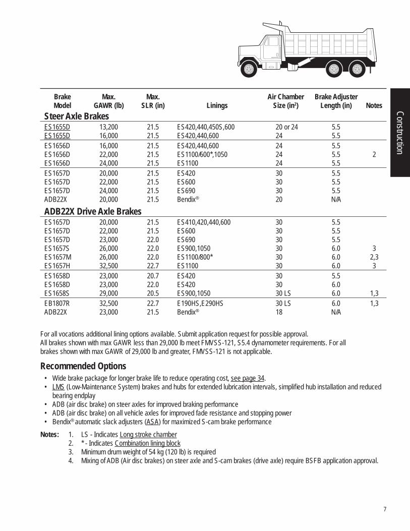
For all vocations additional lining options available. Submit application request for possible approval.All brakes shown with max GAWR less than 29,000 lb meet FMVSS-121, S5.4 dynamometer requirements. For all brakes shown with max GAWR of 29,000 lb and greater, FMVSS-121 is not applicable.
Recommended Options• Wide brake package for longer brake life to reduce operating cost, see page 34.• LMS (Low-Maintenance System) brakes and hubs for extended lubrication intervals, simplifi ed hub installation and reduced
bearing endplay• ADB (air disc brake) on steer axles for improved braking performance • ADB (air disc brake) on all vehicle axles for improved fade resistance and stopping power • Bendix® automatic slack adjusters (ASA) for maximized S-cam brake performance
Notes: 1. LS - Indicates Long stroke chamber 2. * - Indicates Combination lining block 3. Minimum drum weight of 54 kg (120 lb) is required 4. Mixing of ADB (Air disc brakes) on steer axle and S-cam brakes (drive axle) require BSFB application approval.
Brake Max. Max. Air Chamber Brake Adjuster Model GAWR (lb) SLR (in) Linings Size (in2) Length (in) NotesSteer Axle Brakes
ES1655D 13,200 21.5 ES420,440,450S,600 20 or 24 5.5 ES1655D 16,000 21.5 ES420,440,600 24 5.5 ES1656D 16,000 21.5 ES420,440,600 24 5.5 ES1656D 22,000 21.5 ES1100/600*,1050 24 5.5 2 ES1656D 24,000 21.5 ES1100 24 5.5 ES1657D 20,000 21.5 ES420 30 5.5 ES1657D 22,000 21.5 ES600 30 5.5 ES1657D 24,000 21.5 ES690 30 5.5 ADB22X 20,000 21.5 Bendix® 20 N/AADB22X Drive Axle Brakes
ES1657D 20,000 21.5 ES410,420,440,600 30 5.5 ES1657D 22,000 21.5 ES600 30 5.5 ES1657D 23,000 22.0 ES690 30 5.5 ES1657S 26,000 22.0 ES900,1050 30 6.0 3 ES1657M 26,000 22.0 ES1100/800* 30 6.0 2,3 ES1657H 32,500 22.7 ES1100 30 6.0 3 ES1658D 23,000 20.7 ES420 30 5.5 ES1658D 23,000 22.0 ES420 30 6.0 ES1658S 29,000 20.5 ES900,1050 30 LS 6.0 1,3 EB1807R 32,500 22.7 E190HS,E290HS 30 LS 6.0 1,3 ADB22X 23,000 21.5 Bendix® 18 N/A
Construction
8
Defi nitions Vehicles used to transport people and equipment for the purpose of extinguishing fi res or ambulance service Mileage is typically under 20,000 miles per year Typical vehicle routes are three (3) miles between start and stop Multiple high deceleration stops are common Auxiliary retarders are common Higher parking performance required
Typical Vehicle TypesAerial Ladders PumpersAerial Platforms AmbulanceTankers
Vehicle Confi guration4 x 2, 4 x 4, or 6 x 4 straight trucks
General Requirements• Anti-compounding air system • Cam same operation for all steerable axle brakes and EB1807R brakes • Air chamber bracket with gusset for all Fire Service applications, see page 45 • Air chamber bracket assembly gusset and additional camshaft bracket support see page 45, attached to the axle housing
when the: a. Brake centerline to air chamber centerline distance (BCCC dimension) is greater than 343 mm [13.5"] b. Application use a type 30/36 or 36/36 Spring brake chambers. c. Camshaft brackets with BCCC dimension of less than 8.12" does not require a gusset or additional support. d. Super Single Tire (Wide Base Tires)Note: The above support can be supplied by BSFB or the vehicle manufacturer but
must be approved by BSFB Application Engineering Department.• Applications for use in countries other than the USA and Canada must be reviewed by BSFB Application Engineering • Vehicle manufacturer is responsible for air system design, parking and stopping distance performance. • For all S-cam brake models the camshaft input torque is limited to 2545 N•m [22,500 in-lbs]. • Applications on vehicles with fi xed or liftable auxiliary axles (tag or pusher) must be approved on an individual basis by the
BSFB Application Engineering Department, as auxiliary axles may impact the braking performance of the vehicle.
General Recommendations • Cam same for all brake assemblies • Dust shields for all applications • Use Auxiliary retarders per TMC RP636 • Brake drum / Rotor material specifi cation per SAE J431. Drum / rotor surface fi nish 4.57 micrometer [180 max microinch]
and .38 mm [.015"] runout, when mounted on a hub rotated on bearings. See notes section for Minimum Drum Weight requirements
• Brake air system balance per TMC RP632
Fire Service
9
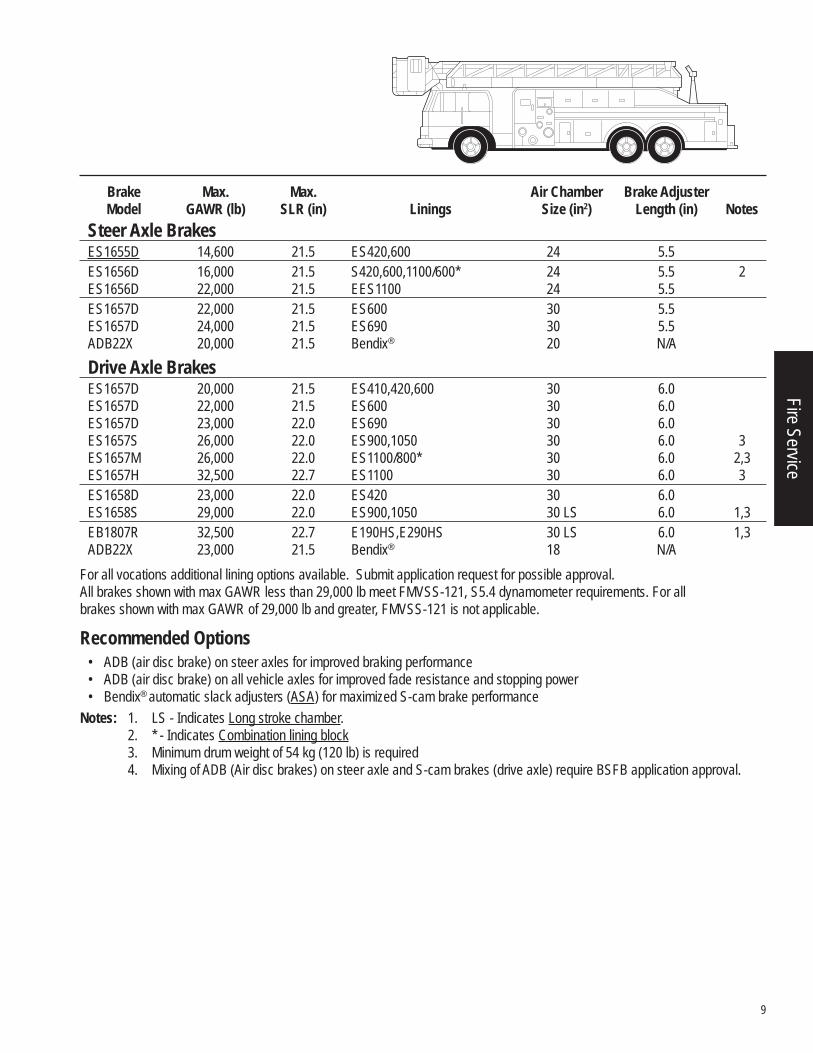
For all vocations additional lining options available. Submit application request for possible approval.All brakes shown with max GAWR less than 29,000 lb meet FMVSS-121, S5.4 dynamometer requirements. For all brakes shown with max GAWR of 29,000 lb and greater, FMVSS-121 is not applicable.
Recommended Options• ADB (air disc brake) on steer axles for improved braking performance • ADB (air disc brake) on all vehicle axles for improved fade resistance and stopping power • Bendix® automatic slack adjusters (ASA) for maximized S-cam brake performance
Notes: 1. LS - Indicates Long stroke chamber. 2. * - Indicates Combination lining block 3. Minimum drum weight of 54 kg (120 lb) is required 4. Mixing of ADB (Air disc brakes) on steer axle and S-cam brakes (drive axle) require BSFB application approval.
Brake Max. Max. Air Chamber Brake Adjuster Model GAWR (lb) SLR (in) Linings Size (in2) Length (in) NotesSteer Axle Brakes
ES1655D 14,600 21.5 ES420,600 24 5.5 ES1656D 16,000 21.5 S420,600,1100/600* 24 5.5 2 ES1656D 22,000 21.5 EES1100 24 5.5 ES1657D 22,000 21.5 ES600 30 5.5 ES1657D 24,000 21.5 ES690 30 5.5 ADB22X 20,000 21.5 Bendix® 20 N/ADrive Axle Brakes
ES1657D 20,000 21.5 ES410,420,600 30 6.0 ES1657D 22,000 21.5 ES600 30 6.0 ES1657D 23,000 22.0 ES690 30 6.0 ES1657S 26,000 22.0 ES900,1050 30 6.0 3 ES1657M 26,000 22.0 ES1100/800* 30 6.0 2,3 ES1657H 32,500 22.7 ES1100 30 6.0 3 ES1658D 23,000 22.0 ES420 30 6.0 ES1658S 29,000 22.0 ES900,1050 30 LS 6.0 1,3 EB1807R 32,500 22.7 E190HS,E290HS 30 LS 6.0 1,3 ADB22X 23,000 21.5 Bendix® 18 N/A
Fire Service
10
Defi nitions Movement of heavy equipment or materials at legal maximums or special permit loadings Operation on road surfaces of concrete, asphalt and maintained gravel High horsepower engines and auxiliary gear boxes are typically used Vehicles may be equipped with two retarders 100% load going and empty return
Typical Vehicle TypesTractor/Trailer Combination:
Equipment HaulingFlatbedLowboySteel Hauling
General Requirements• Anti-compounding air system • Cam same operation for all steerable axle brakes and EB1807R brakes • Air chamber bracket with gusset for all Heavy Haul applications, see page 45 • Air chamber bracket assembly gusset and additional camshaft bracket support see page 45, attached to the axle housing
when the: a. Brake centerline to air chamber centerline distance (BCCC dimension) is greater than 343 mm [13.5"] b. Application use a type 30/36 or 36/36 Spring brakes chambers. c. Camshaft brackets with BCCC dimension of less than 8.12" does not require a gusset or additional support. d. Super Single Tire (Wide Base)Note: The above support can be supplied by BSFB or the vehicle manufacturer but
must be approved by BSFB Application Engineering Department.• Applications for use in countries other than the USA and Canada must be reviewed by BSFB Application Engineering. • Vehicle manufacturer is responsible for air system design, parking and stopping distance performance. • For all S-cam brake models the camshaft input torque is limited to 2545 N•m [22,500 in-lbs]. • Applications on vehicles with fi xed or liftable auxiliary axles (tag or pusher) must be approved on an individual basis by the
BSFB Application Engineering Department, as auxiliary axles may impact the braking performance of the vehicle.
General Recommendations • Cam same for all brake assemblies • Dust shields for all applications • Use Auxiliary retarders per TMC RP636 • Drum brake / Rotor material specifi cation per SAE J431. Drum / rotor surface fi nish 4.57 micrometer [180 max microinch]
and .38 mm [.015”] runout, when mounted on a hub rotated on bearings. See notes section for Minimum Drum Weight requirements
• Brake air system balance per TMC RP632
Heavy Haul
11
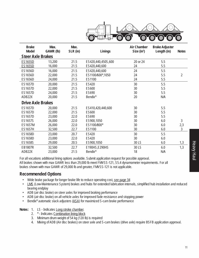
Brake Max. Max. Air Chamber Brake Adjuster Model GAWR (lb) SLR (in) Linings Size (in2) Length (in) NotesSteer Axle Brakes
ES1655D 13,200 21.5 ES420,440,450S,600 20 or 24 5.5 ES1655D 16,000 21.5 ES420,440,600 24 5.5 ES1656D 16,000 21.5 ES420,440,600 24 5.5 ES1656D 22,000 21.5 ES1100/600*,1050 24 5.5 2 ES1656D 24,000 21.5 ES1100 24 5.5 ES1657D 20,000 21.5 ES420 30 5.5 ES1657D 22,000 21.5 ES600 30 5.5 ES1657D 24,000 21.5 ES690 30 5.5 ADB22X 20,000 21.5 Bendix® 20 N/ADrive Axle Brakes
ES1657D 20,000 21.5 ES410,420,440,600 30 5.5 ES1657D 22,000 21.5 ES600 30 5.5 ES1657D 23,000 22.0 ES690 30 5.5 ES1657S 26,000 22.0 ES900,1050 30 6.0 3 ES1657M 26,000 22.0 ES1100/800* 30 6.0 2,3 ES1657H 32,500 22.7 ES1100 30 6.0 3 ES1658D 23,000 20.7 ES420 30 5.5 ES1658D 23,000 22.0 ES420 30 6.0 ES1658S 29,000 20.5 ES900,1050 30 LS 6.0 1,3 EB1807R 32,500 22.7 E190HS,E290HS 30 LS 6.0 1,3 ADB22X 23,000 21.5 Bendix® 18 N/A
For all vocations additional lining options available. Submit application request for possible approval.All brakes shown with max GAWR less than 29,000 lb meet FMVSS-121, S5.4 dynamometer requirements. For all brakes shown with max GAWR of 29,000 lb and greater, FMVSS-121 is not applicable.
Recommended Options • Wide brake package for longer brake life to reduce operating cost, see page 34 • LMS (Low-Maintenance System) brakes and hubs for extended lubrication intervals, simplifi ed hub installation and reduced
bearing endplay • ADB (air disc brake) on steer axles for improved braking performance • ADB (air disc brake) on all vehicle axles for improved fade resistance and stopping power • Bendix® automatic slack adjusters (ASA) for maximized S-cam brake performance
Notes: 1. LS - Indicates Long stroke chamber. 2. * - Indicates Combination lining block 3. Minimum drum weight of 54 kg (120 lb) is required 4. Mixing of ADB (Air disc brakes) on steer axle and S-cam brakes (drive axle) require BSFB application approval.
Heavy Haul
12
Defi nitions Transporting people and sometimes light freight between cities and/or suburban areas Operation on road surfaces of concrete, asphalt, maintained gravel, crushed rock, or hard packed dirt High mileage operation Typical vehicle routes exceed 30 miles between start and stop No towed load allowed
Typical Vehicle Types Tour CoachCross Country Coach
Vehicle Confi guration 6 x 2 straight coach with non-liftable tag or pusher axles
General Requirements • Anti-compounding air system • Cam same operation for all brakes • Air chamber bracket with gusset for all intercity coach applications, see page 45 • Air chamber bracket assembly gusset and additional camshaft bracket support see page 45, attached to the axle housing
when the: a. Brake centerline to air chamber centerline distance (BCCC dimension) is greater than 343 mm [13.5"] b. Application use a type 30/36 or 36/36 Spring brake chambers. c. Camshaft brackets with BCCC dimension of less than 8.12” does not require a gusset or additional support. d. Super Single Tire (Wide Base)Note: The above support can be supplied by BSFB or the vehicle manufacturer but
must be approved by BSFB Application Engineering Department.• Applications for use in countries other than the USA and Canada must be reviewed by BSFB Application Engineering. • Vehicle manufacturer is responsible for air system design, parking and stopping distance performance. • For all S-cam brake models the camshaft input torque is limited to 2545 N•m [22,500 in-lbs]. • Applications on vehicles with fi xed or liftable auxiliary axles (tag or pusher) must be approved on an individual basis by the
BSFB Application Engineering Department, as auxiliary axles may impact the braking performance of the vehicle.
General Recommendations • Dust shields for all applications • Use Auxiliary retarders per TMC RP636 • Brake drum / Rotor material specifi cation per SAE J431. Drum / rotor surface fi nish 4.57 micrometers [180 max microinch]
and .38 mm [.015"] runout, when mounted on a hub rotated on bearings. See notes section for Minimum Drum Weight requirements
• Brake air system balance per TMC RP632
Intercity Coach
13
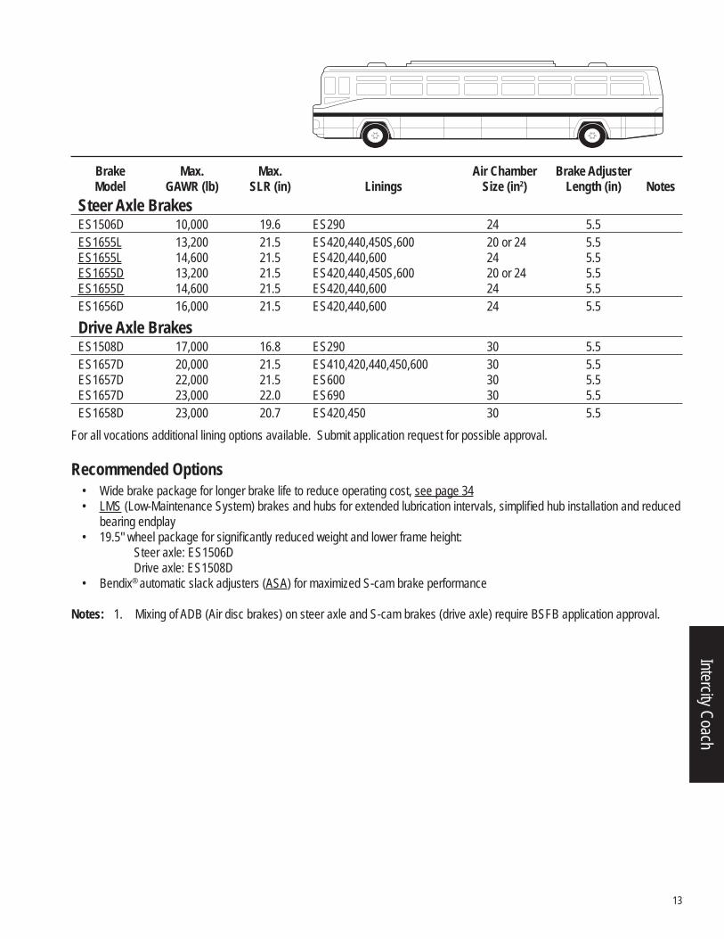
For all vocations additional lining options available. Submit application request for possible approval.
Recommended Options • Wide brake package for longer brake life to reduce operating cost, see page 34 • LMS (Low-Maintenance System) brakes and hubs for extended lubrication intervals, simplifi ed hub installation and reduced
bearing endplay • 19.5" wheel package for signifi cantly reduced weight and lower frame height:
Steer axle: ES1506DDrive axle: ES1508D
• Bendix® automatic slack adjusters (ASA) for maximized S-cam brake performance
Notes: 1. Mixing of ADB (Air disc brakes) on steer axle and S-cam brakes (drive axle) require BSFB application approval.
Brake Max. Max. Air Chamber Brake Adjuster Model GAWR (lb) SLR (in) Linings Size (in2) Length (in) NotesSteer Axle Brakes
ES1506D 10,000 19.6 ES290 24 5.5 ES1655L 13,200 21.5 ES420,440,450S,600 20 or 24 5.5 ES1655L 14,600 21.5 ES420,440,600 24 5.5 ES1655D 13,200 21.5 ES420,440,450S,600 20 or 24 5.5 ES1655D 14,600 21.5 ES420,440,600 24 5.5 ES1656D 16,000 21.5 ES420,440,600 24 5.5Drive Axle Brakes
ES1508D 17,000 16.8 ES290 30 5.5 ES1657D 20,000 21.5 ES410,420,440,450,600 30 5.5 ES1657D 22,000 21.5 ES600 30 5.5 ES1657D 23,000 22.0 ES690 30 5.5 ES1658D 23,000 20.7 ES420,450 30 5.5
Intercity Coach
14
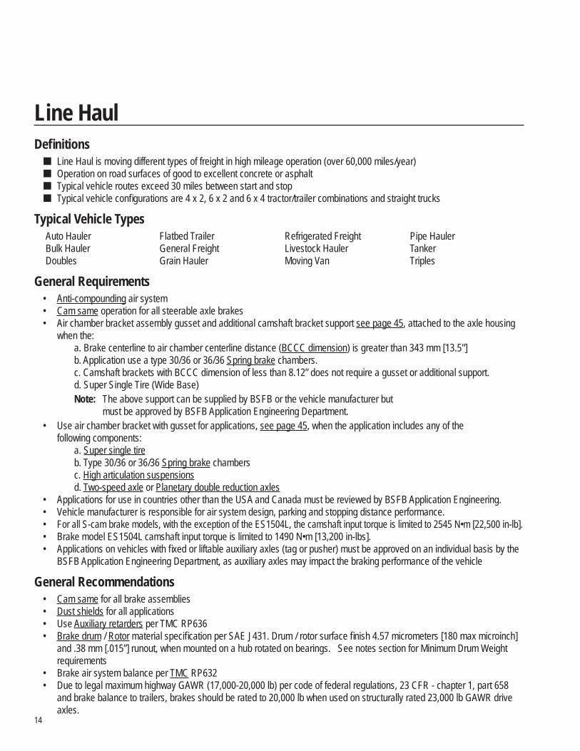
Defi nitions Line Haul is moving different types of freight in high mileage operation (over 60,000 miles/year) Operation on road surfaces of good to excellent concrete or asphalt Typical vehicle routes exceed 30 miles between start and stop Typical vehicle confi gurations are 4 x 2, 6 x 2 and 6 x 4 tractor/trailer combinations and straight trucks
Typical Vehicle Types Auto Hauler Flatbed Trailer Refrigerated Freight Pipe Hauler Bulk Hauler General Freight Livestock Hauler Tanker Doubles Grain Hauler Moving Van Triples
General Requirements • Anti-compounding air system • Cam same operation for all steerable axle brakes • Air chamber bracket assembly gusset and additional camshaft bracket support see page 45, attached to the axle housing
when the: a. Brake centerline to air chamber centerline distance (BCCC dimension) is greater than 343 mm [13.5"] b. Application use a type 30/36 or 36/36 Spring brake chambers. c. Camshaft brackets with BCCC dimension of less than 8.12” does not require a gusset or additional support. d. Super Single Tire (Wide Base)Note: The above support can be supplied by BSFB or the vehicle manufacturer but
must be approved by BSFB Application Engineering Department.• Use air chamber bracket with gusset for applications, see page 45, when the application includes any of the
following components:a. Super single tire b. Type 30/36 or 36/36 Spring brake chambers c. High articulation suspensions d. Two-speed axle or Planetary double reduction axles
• Applications for use in countries other than the USA and Canada must be reviewed by BSFB Application Engineering. • Vehicle manufacturer is responsible for air system design, parking and stopping distance performance. • For all S-cam brake models, with the exception of the ES1504L, the camshaft input torque is limited to 2545 N•m [22,500 in-lb]. • Brake model ES1504L camshaft input torque is limited to 1490 N•m [13,200 in-lbs]. • Applications on vehicles with fi xed or liftable auxiliary axles (tag or pusher) must be approved on an individual basis by the
BSFB Application Engineering Department, as auxiliary axles may impact the braking performance of the vehicle
General Recommendations • Cam same for all brake assemblies • Dust shields for all applications • Use Auxiliary retarders per TMC RP636 • Brake drum / Rotor material specifi cation per SAE J431. Drum / rotor surface fi nish 4.57 micrometers [180 max microinch]
and .38 mm [.015”] runout, when mounted on a hub rotated on bearings. See notes section for Minimum Drum Weight requirements
• Brake air system balance per TMC RP632 • Due to legal maximum highway GAWR (17,000-20,000 lb) per code of federal regulations, 23 CFR - chapter 1, part 658
and brake balance to trailers, brakes should be rated to 20,000 lb when used on structurally rated 23,000 lb GAWR drive axles.
Line Haul
15
For all vocations additional lining options available. Submit application request for possible approval. All brakes shown meet FMVSS-121, S5.4 dynamometer requirements. Recommended Options
• Wide brake package for longer brake life to reduce operating cost, see page 34 • LMS (Low-Maintenance System) brakes and hubs for extended lubrication intervals, simplifi ed hub installation and reduced
bearing endplay • ADB (air disc brake) on steer axles for improved braking performance • ADB (air disc brake) on all vehicle axles for improved fade resistance and stopping power • 19.5" wheel package for signifi cantly reduced weight and lower 5th wheel height:
Steer axle: ES1504D or ES1506DDrive axle: ES1508D
• Bendix® automatic slack adjusters (ASA) for maximized S-cam brake performance.
Notes: 1. Mixing of ADB (Air disc brakes) on steer axle and S-cam brakes (drive axle) require BSFB application approval.
Brake Max. Max. Air Chamber Brake Adjuster Model GAWR (lb) SLR (in) Linings Size (in2) Length (in) NotesSteer Axle Brakes
ES1504L 12,000 21.5 ES420 16 or 20 5.5 ES1504L 13,200 21.5 ES420 20 5.5 ES1504D 12,000 19.6 ES450S 20 5.5 ES1504D 13,200 21.5 ES420,440,600 20 or 24 5.5 ES1506D 10,000 19.6 ES290 24 5.5 ES1655L 13,200 21.5 ES420,440,450S,600 20 or 24 5.5 ES1655L 14,600 21.5 ES420,440,600 24 5.5 ES1655D 13,200 21.5 ES420,440,450S,600 20 or 24 5.5 ES1655D 14,600 21.5 ES420,440,600 24 5.5 ADB22X 20,000 21.5 Bendix® 20 N/A
Drive Axle Brakes ES1508D 17,000 16.8 ES290 30 5.5 ES1657L 20,000 21.5 ES410,420,440,450,600 30 5.5 ES1657D 20,000 21.5 ES410,420,440,450,600 30 5.5 ES1658L 20,000 21.5 ES420,450 30 5.5 ES1658D 20,000 21.5 ES420,450 30 5.5 ADB22X 23,000 21.5 Bendix® 18 N/A
Line Haul
16
Defi nitions Movement of logs, chips and pulp between logging sites and/or mill High horsepower engines are typically used in this vocation Typical vehicle routes are between three (3) and thirty (30) miles from start to stop 90% of loaded operation on road surfaces of concrete, asphalt, maintained gravel, crushed rock or hard packed dirt and up
to 10% of loaded operation into sandy or muddy job sites 100% load going and empty return
Typical Vehicles Types Chip Hauler Straight Truck with Trailer Log Hauler Tractors with Pole Trailers
General Requirements • Anti-compounding air system • Cam same operation for all steerable axle brakes and EB1807R brakes • Air chamber bracket with gusset for all logging applications, see page 45 • Air chamber bracket assembly gusset and additional camshaft bracket support see page 45, attached to the axle housing
when the: a. Brake centerline to air chamber centerline distance (BCCC dimension) is greater than 343 mm [13.5”] b. Application use a type 30/36 or 36/36 Spring brake chambers. c. Camshaft brackets with BCCC dimension of less than 8.12” does not require a gusset or additional support. d. Super Single Tire (Wide Base)Note: The above support can be supplied by BSFB or the vehicle manufacturer but
must be approved by BSFB Application Engineering Department.• Applications for use in countries other than the USA and Canada must be reviewed by BSFB Application Engineering. • Vehicle manufacturer is responsible for air system design, parking and stopping distance performance. • For all S-cam brake models the camshaft input torque is limited to 2545 N•m [22,500 in-lbs]. • Applications on vehicles with fi xed or liftable auxiliary axles (tag or pusher) must be approved on an individual basis by the
BSFB Application Engineering Department, as auxiliary axles may impact the braking performance of the vehicle.
General Recommendations • Cam same for all brake assemblies • Dust shields for all applications • Use Auxiliary retarders per TMC RP636 • Brake drum / Rotor material specifi cation per SAE J431. Drum / rotor surface fi nish 4.57 micrometer [180 max microinch]
and .38 mm [.015"] runout, when mounted on a hub rotated on bearings. See notes section for Minimum Drum Weight requirements
• Brake air system balance per TMC RP632
Logging
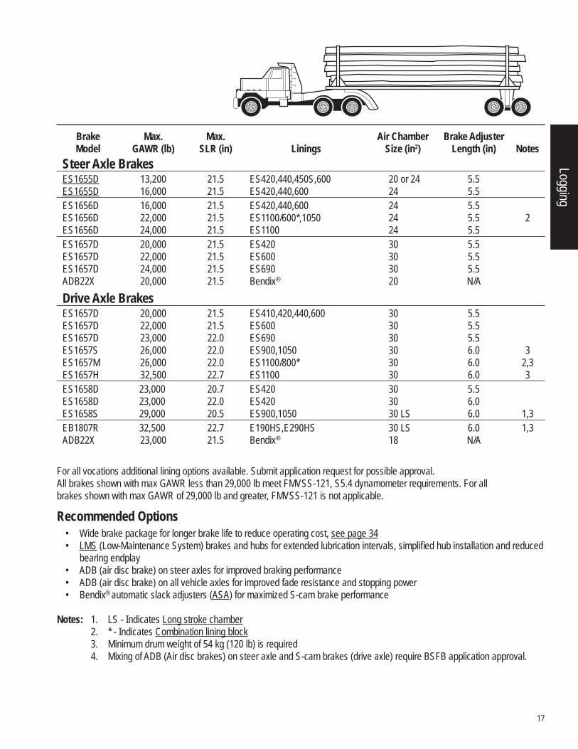
17
For all vocations additional lining options available. Submit application request for possible approval.All brakes shown with max GAWR less than 29,000 lb meet FMVSS-121, S5.4 dynamometer requirements. For all brakes shown with max GAWR of 29,000 lb and greater, FMVSS-121 is not applicable.
Recommended Options • Wide brake package for longer brake life to reduce operating cost, see page 34 • LMS (Low-Maintenance System) brakes and hubs for extended lubrication intervals, simplifi ed hub installation and reduced
bearing endplay • ADB (air disc brake) on steer axles for improved braking performance • ADB (air disc brake) on all vehicle axles for improved fade resistance and stopping power • Bendix® automatic slack adjusters (ASA) for maximized S-cam brake performance
Notes: 1. LS - Indicates Long stroke chamber 2. * - Indicates Combination lining block 3. Minimum drum weight of 54 kg (120 lb) is required 4. Mixing of ADB (Air disc brakes) on steer axle and S-cam brakes (drive axle) require BSFB application approval.
Brake Max. Max. Air Chamber Brake Adjuster Model GAWR (lb) SLR (in) Linings Size (in2) Length (in) NotesSteer Axle Brakes
ES1655D 13,200 21.5 ES420,440,450S,600 20 or 24 5.5 ES1655D 16,000 21.5 ES420,440,600 24 5.5 ES1656D 16,000 21.5 ES420,440,600 24 5.5 ES1656D 22,000 21.5 ES1100/600*,1050 24 5.5 2 ES1656D 24,000 21.5 ES1100 24 5.5 ES1657D 20,000 21.5 ES420 30 5.5 ES1657D 22,000 21.5 ES600 30 5.5 ES1657D 24,000 21.5 ES690 30 5.5 ADB22X 20,000 21.5 Bendix® 20 N/ADrive Axle Brakes
ES1657D 20,000 21.5 ES410,420,440,600 30 5.5 ES1657D 22,000 21.5 ES600 30 5.5 ES1657D 23,000 22.0 ES690 30 5.5 ES1657S 26,000 22.0 ES900,1050 30 6.0 3 ES1657M 26,000 22.0 ES1100/800* 30 6.0 2,3 ES1657H 32,500 22.7 ES1100 30 6.0 3 ES1658D 23,000 20.7 ES420 30 5.5 ES1658D 23,000 22.0 ES420 30 6.0 ES1658S 29,000 20.5 ES900,1050 30 LS 6.0 1,3 EB1807R 32,500 22.7 E190HS,E290HS 30 LS 6.0 1,3 ADB22X 23,000 21.5 Bendix® 18 N/A
Logging
18
Defi nitions Movement of rock, ore, gravel and minerals between mine sites and delivery sites High horsepower engines are typically used in this vocation Typical vehicle routes are between three (3) and thirty (30) miles from start to stop 90% operation on-highway and up to 10% into sandy or muddy job site 100% load going and empty return
Typical Vehicle Types Bottom Dump Trailer Transfer Dump Semi-End Dump Hopper Trailer Combinations
General Requirements • Anti-compounding air system • Cam same operation for all steerable axle brakes and EB1807R brakes • Air chamber bracket with gusset for all mining applications, see page 45 • Air chamber bracket assembly gusset and additional camshaft bracket support see page 45, attached to the axle housing
when the: a. Brake centerline to air chamber centerline distance (BCCC dimension) is greater than 343 mm [13.5"] b. Application use a type 30/36 or 36/36 Spring brake chambers. c. Camshaft brackets with BCCC dimension of less than 8.12" does not require a gusset or additional support. d. Super Single Tire (Wide Base)Note: The above support can be supplied by BSFB or the vehicle manufacturer but must be approved by BSFB Application Engineering Department.
• Applications for use in countries other than the USA and Canada must be reviewed by BSFB Application Engineering. • Vehicle manufacturer is responsible for air system design, parking and stopping distance performance. • For all S-cam brake models the camshaft input torque is limited to 2545 N•m [22,500 in-lbs]. • Applications on vehicles with fi xed or liftable auxiliary axles (tag or pusher) must be approved on an individual basis by the
BSFB Application Engineering Department, as auxiliary axles may impact the braking performance of the vehicle.
General Recommendations • Cam same for all brake assemblies • Dust shields for all applications • Use Auxiliary retarders per TMC RP636 • Drum brake / Rotor material specifi cation per SAE J431. Drum / rotor surface fi nish 4.57 micrometer [180 max microinch]
and .38 mm [.015”] runout, when mounted on a hub rotated on bearings. See notes section for Minimum Drum Weight requirements
• Brake air system balance per TMC RP632
Mining
19
For all vocations additional lining options available. Submit application request for possible approval.All brakes shown with max GAWR less than 29,000 lb meet FMVSS-121, S5.4 dynamometer requirements. For all brakes shown with max GAWR of 29,000 lb and greater, FMVSS-121 is not applicable.
Recommended Options • Wide brake package for longer brake life to reduce operating cost, see page 34 • LMS (Low-Maintenance System) brakes and hubs for extended lubrication intervals, simplifi ed hub installation and reduced
bearing endplay • ADB (air disc brake) on steer axles for improved braking performance • ADB (air disc brake) on all vehicle axles for improved fade resistance and stopping power • Bendix® automatic slack adjusters (ASA) for maximized S-cam brake performance
Notes: 1. LS - Indicates Long stroke chamber 2. * - Indicates Combination lining block 3. Minimum drum weight of 54kg (120 lb) is required 4. Mixing of ADB (Air disc brakes) on steer axle and S-cam brakes (drive axle) require BSFB application approval.
Brake Max. Max. Air Chamber Brake Adjuster Model GAWR (lb) SLR (in) Linings Size (in2) Length (in) NotesSteer Axle Brakes
ES1655D 13,200 21.5 ES420,440,450S,600 20 or 24 5.5 ES1655D 16,000 21.5 ES420,440,600 24 5.5 ES1656D 16,000 21.5 ES420,440,600 24 5.5 ES1656D 22,000 21.5 ES1100/600*,1050 24 5.5 2 ES1656D 24,000 21.5 ES1100 24 5.5 ES1657D 20,000 21.5 ES420 30 5.5 ES1657D 22,000 21.5 ES600 30 5.5 ES1657D 24,000 21.5 ES690 30 5.5 ADB22X 20,000 21.5 Bendix® 20 N/ADrive Axle Brakes
ES1657D 20,000 21.5 ES410,420,440,600 30 5.5 ES1657D 22,000 21.5 ES600 30 5.5 ES1657D 23,000 22.0 ES690 30 5.5 ES1657S 26,000 22.0 ES900,1050 30 6.0 3 ES1657M 26,000 22.0 ES1100/800* 30 6.0 2,3 ES1657H 32,500 22.7 ES1100 30 6.0 3 ES1658D 23,000 20.7 ES420 30 5.5 ES1658D 23,000 22.0 ES420 30 6.0 ES1658S 29,000 20.5 ES900,1050 30 LS 6.0 1,3 ES1807R 32,500 22.7 E190HS, E290HS 30LS 6.0 1,3 ADB22X 23,000 21.5 Bendix® 18 N/A
Mining
20
Defi nitions Vehicles generally used for non-commercial transportation and as traveling domiciles for families 100% loaded full time May pull small passenger car, SUV or pick-up truck Typical vehicle routes exceed 30 miles between start and stop Annual mileage will be under 30,000 Typical operation is on paved roads and short distances within campgrounds and parks
Typical Vehicle Types Recreational Vehicles
Vehicle Confi gurations Straight coach type vehicles with towing ability:
4 x 2 straight coach6 x 2 (with non-liftable tag or pusher axles)
General Requirements • Anti-compounding air system • Cam same operation for all steerable axle brakes • Air chamber bracket assembly gusset and additional camshaft bracket support see page 45, attached to the axle housing
when the: a. Brake centerline to air chamber centerline distance (BCCC dimension) is greater than 343 mm [13.5"] b. Application use a type 30/36 or 36/36 Spring brake chambers. c. Camshaft brackets with BCCC dimension of less than 8.12" does not require a gusset or additional support. d. Super Single Tire (Wide Base)Note: The above support can be supplied by BSFB or the vehicle manufacturer but
must be approved by BSFB Application Engineering Department.• Air chamber bracket with gusset for applications, see page 45, when the application includes any of the following
components: a. Super single tiresb. Type 30/36 or 36/36 Spring brake chambers.
• BSFB Application Engineering approval for: a. Vehicle towing unbraked trailer vehicle. b. Applications for use in countries other than the USA and Canada must be reviewed by BSFB Application
Engineering. • Vehicle manufacturer is responsible for air system design, parking and stopping distance performance. • For all S-cam brake models the camshaft input torque is limited to 2545 N•m [22,500 in-lbs].
General Recommendations • Cam same for all brake assemblies • Dust shields for all applications • Use Auxiliary retarders per TMC RP636 • Brake drum / Rotor material specifi cation per SAE J431. Drum / rotor surface fi nish 4.57 micrometers [180 max microinch]
and .38 mm [.015"] runout, when mounted on a hub rotated on bearings. See notes section for Minimum Drum Weight requirements
• Brake air system balance per TMC RP632
Motorhome
21
For all vocations additional lining options available. Submit application request for possible approval. All brakes shown meet FMVSS-121, S5.4 dynamometer requirements.
Recommended Options • Wide brake package for longer brake life to reduce operating cost, see page 34 • LMS (Low-Maintenance System) brakes and hubs for extended lubrication intervals, simplifi ed hub installation and reduced
bearing endplay • ADB (air disc brake) on steer axles for improved braking performance • ADB (air disc brake) on all vehicle axles for improved fade resistance and stopping power • 19.5" wheel package for signifi cantly reduced weight and lower frame height:
Steer axle: ES1504D or ES1506DDrive axle: ES1508D
• Bendix® automatic slack adjusters (ASA) for maximized S-cam brake performance Notes: 1. Mixing of ADB (Air disc brakes) on steer axle and S-cam brakes (drive axle) require BSFB application approval. 2. Air system Crack pressure for ADB must be approved by BSFB Application Engineering.
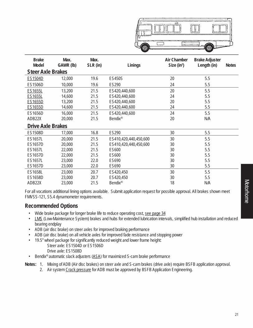
Brake Max. Max. Air Chamber Brake Adjuster Model GAWR (lb) SLR (in) Linings Size (in2) Length (in) NotesSteer Axle Brakes
ES1504D 12,000 19.6 ES450S 20 5.5 ES1506D 10,000 19.6 ES290 24 5.5 ES1655L 13,200 21.5 ES420,440,600 20 5.5 ES1655L 14,600 21.5 ES420,440,600 24 5.5 ES1655D 13,200 21.5 ES420,440,600 20 5.5 ES1655D 14,600 21.5 ES420,440,600 24 5.5 ES1656D 16,000 21.5 ES420,440,600 24 5.5 ADB22X 20,000 21.5 Bendix® 20 N/ADrive Axle Brakes
ES1508D 17,000 16.8 ES290 30 5.5 ES1657L 20,000 21.5 ES410,420,440,450,600 30 5.5 ES1657D 20,000 21.5 ES410,420,440,450,600 30 5.5 ES1657L 22,000 21.5 ES600 30 5.5 ES1657D 22,000 21.5 ES600 30 5.5 ES1657L 23,000 22.0 ES690 30 5.5 ES1657D 23,000 22.0 ES690 30 5.5 ES1658L 23,000 20.7 ES420,450 30 5.5 ES1658D 23,000 20.7 ES420,450 30 5.5 ADB22X 23,000 21.5 Bendix® 18 N/A
Motorhome
22
Defi nitions Movement of production related products, supplies and tools between job sites Movement of processing equipment and laboratories on job sites Low mileage operation on road surfaces made of concrete, asphalt, maintained gravel, crushed rock or hard packed dirt
Typical Vehicle Types Cementing Vehicle Geophysical Exploration Demolition Rigging Truck Drill Rig Tanker Fracturing Truck Winch Truck
General Requirements• Anti-compounding air system • Cam same operation for all steerable axle brakes and EB1807R brakes • Air chamber bracket with gusset for all oil fi eld applications, see page 45 • Air chamber bracket assembly gusset and additional camshaft bracket support see page 45, attached to the axle housing
when the: a. Brake centerline to air chamber centerline distance (BCCC dimension) is greater than 343 mm [13.5"] b. Application use a type 30/36 or 36/36 Spring brake chambers. c. Camshaft brackets with BCCC dimension of less than 8.12" does not require a gusset or additional support. d. Super Single Tire (Wide Base)Note: The above support can be supplied by BSFB or the vehicle manufacturer but
must be approved by BSFB Application Engineering Department.• Applications for use in countries other than the USA and Canada must be reviewed by BSFB Application Engineering.• Vehicle manufacturer is responsible for air system design, parking and stopping distance performance. • For all S-cam brake models the camshaft input torque is limited to 2545 N•m [22,500 in-lbs]. • Applications on vehicles with fi xed or liftable auxiliary axles (tag or pusher) must be approved on an individual basis by the
BSFB Application Engineering Department, as auxiliary axles may impact the braking performance of the vehicle.
General Recommendations• Cam same for all brake assemblies • Dust shields for all applications • Use Auxiliary retarders per TMC RP636 • Brake drum / Rotor material specifi cation per SAE J431. Drum / rotor surface fi nish 4.57 micrometer [180 max microinch]
and .38 mm [.015"] runout, when mounted on a hub rotated on bearings. See notes section for Minimum Drum Weight requirements
• Brake air system balance per TMC RP632
Oil Field
23
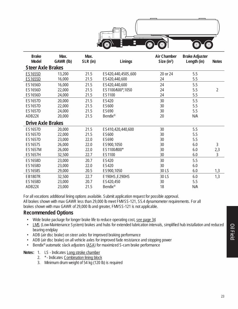
For all vocations additional lining options available. Submit application request for possible approval.All brakes shown with max GAWR less than 29,000 lb meet FMVSS-121, S5.4 dynamometer requirements. For all brakes shown with max GAWR of 29,000 lb and greater, FMVSS-121 is not applicable.Recommended Options
• Wide brake package for longer brake life to reduce operating cost, see page 34 • LMS (Low-Maintenance System) brakes and hubs for extended lubrication intervals, simplifi ed hub installation and reduced
bearing endplay • ADB (air disc brake) on steer axles for improved braking performance • ADB (air disc brake) on all vehicle axles for improved fade resistance and stopping power • Bendix® automatic slack adjusters (ASA) for maximized S-cam brake performance
Notes: 1. LS - Indicates Long stroke chamber 2. * - Indicates Combination lining block 3. Minimum drum weight of 54 kg (120 lb) is required
Brake Max. Max. Air Chamber Brake Adjuster Model GAWR (lb) SLR (in) Linings Size (in2) Length (in) NotesSteer Axle Brakes
ES1655D 13,200 21.5 ES420,440,450S,600 20 or 24 5.5 ES1655D 16,000 21.5 ES420,440,600 24 5.5 ES1656D 16,000 21.5 ES420,440,600 24 5.5 ES1656D 22,000 21.5 ES1100/600*,1050 24 5.5 2 ES1656D 24,000 21.5 ES1100 24 5.5 ES1657D 20,000 21.5 ES420 30 5.5 ES1657D 22,000 21.5 ES600 30 5.5 ES1657D 24,000 21.5 ES690 30 5.5 ADB22X 20,000 21.5 Bendix® 20 N/ADrive Axle Brakes
ES1657D 20,000 21.5 ES410,420,440,600 30 5.5 ES1657D 22,000 21.5 ES600 30 5.5 ES1657D 23,000 22.0 ES690 30 5.5 ES1657S 26,000 22.0 ES900,1050 30 6.0 3 ES1657M 26,000 22.0 ES1100/800* 30 6.0 2,3 ES1657H 32,500 22.7 ES1100 30 6.0 3 ES1658D 23,000 20.7 ES420 30 5.5 ES1658D 23,000 22.0 ES420 30 6.0 ES1658S 29,000 20.5 ES900,1050 30 LS 6.0 1,3 EB1807R 32,500 22.7 E190HS,E290HS 30 LS 6.0 1,3 ES1658D 23,000 20.7 ES420,450 30 5.5 ADB22X 23,000 21.5 Bendix® 18 N/A
Oil Field
24
Defi nitions Vehicles used for residential refuse/recycle pickup, typically a high number of stops per mile Vehicles operated in commercial/industrial pickup, typically a low number of stops per mile Vehicles used in transfer/relocation on typically greater than 10-mile trips 90% of loaded operation on road surfaces of concrete, asphalt or maintained gravel and up to 10% of loaded
operation into landfi ll, transfer or recycling sites
Typical Vehicle Types Front/Rear/Side Loader Sewer/Septic/Vacuum Roll-Off Liquid Waste Hauler Scrap Truck Transfer Vehicle Residential/Commercial Pickup Street Sweeper
General Requirements• Anti-compounding air system • Cam same operation for all steerable axle brakes and EB1807R brakes • Air chamber bracket with gusset for all refuse applications, see page 45 • Air chamber bracket assembly gusset and additional camshaft bracket support see page 45, attached to the axle housing
when the: a. Brake centerline to air chamber centerline distance (BCCC dimension) is greater than 343 mm [13.5”] b. Application use a type 30/36 or 36/36 Spring brake chambers. c. Camshaft brackets with BCCC dimension of less than 8.12” does not require a gusset or additional support. d. Super Single Tire (Wide Base)Note: The above support can be supplied by BSFB or the vehicle manufacturer but must be approved by BSFB Application Engineering Department.
• Applications for use in countries other than the USA and Canada must be reviewed by BSFB Application Engineering. • Trucks equipped with remotely controlled neutral brake engagement valves must incorporate a pressure limiting device set
to a maximum pressure of 60 psi and must supply air pressure to all service chambers on the vehicle • Vehicle manufacturer is responsible for air system design, parking and stopping distance performance. • For all brake models the camshaft input torque is limited to 2545 N•m [22,500 in-lbs]. • Applications on vehicles with fi xed or liftable auxiliary axles (tag or pusher) must be approved on an individual basis by the
BSFB Application Engineering Department, as auxiliary axles may impact the braking performance of the vehicle.
General Recommendations • Cam same for all brake assemblies • Dust shields for all applications • Use Auxiliary retarders per TMC RP636 • Brake drum / Rotor material specifi cation per SAE J431. Drum / rotor surface fi nish 4.57 micrometer [180 max microinch]
and .38 mm [.015”] runout, when mounted on a hub rotated on bearings. See notes section for Minimum Drum Weight requirements
• Brake air system balance per TMC RP632
Refuse
25
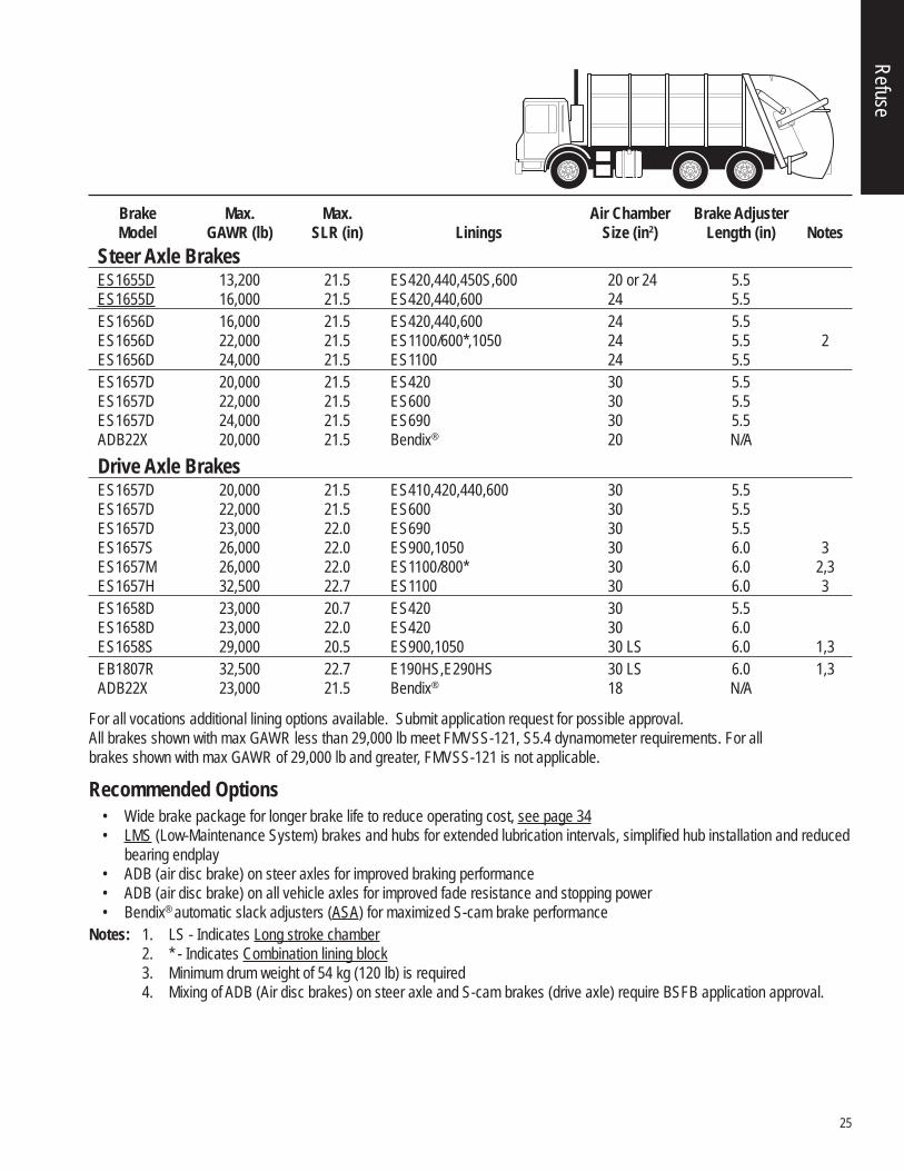
For all vocations additional lining options available. Submit application request for possible approval.All brakes shown with max GAWR less than 29,000 lb meet FMVSS-121, S5.4 dynamometer requirements. For all brakes shown with max GAWR of 29,000 lb and greater, FMVSS-121 is not applicable.
Recommended Options • Wide brake package for longer brake life to reduce operating cost, see page 34 • LMS (Low-Maintenance System) brakes and hubs for extended lubrication intervals, simplifi ed hub installation and reduced
bearing endplay • ADB (air disc brake) on steer axles for improved braking performance • ADB (air disc brake) on all vehicle axles for improved fade resistance and stopping power • Bendix® automatic slack adjusters (ASA) for maximized S-cam brake performance
Notes: 1. LS - Indicates Long stroke chamber 2. * - Indicates Combination lining block 3. Minimum drum weight of 54 kg (120 lb) is required 4. Mixing of ADB (Air disc brakes) on steer axle and S-cam brakes (drive axle) require BSFB application approval.
Brake Max. Max. Air Chamber Brake Adjuster Model GAWR (lb) SLR (in) Linings Size (in2) Length (in) NotesSteer Axle Brakes
ES1655D 13,200 21.5 ES420,440,450S,600 20 or 24 5.5 ES1655D 16,000 21.5 ES420,440,600 24 5.5 ES1656D 16,000 21.5 ES420,440,600 24 5.5 ES1656D 22,000 21.5 ES1100/600*,1050 24 5.5 2 ES1656D 24,000 21.5 ES1100 24 5.5 ES1657D 20,000 21.5 ES420 30 5.5 ES1657D 22,000 21.5 ES600 30 5.5 ES1657D 24,000 21.5 ES690 30 5.5 ADB22X 20,000 21.5 Bendix® 20 N/ADrive Axle Brakes
ES1657D 20,000 21.5 ES410,420,440,600 30 5.5 ES1657D 22,000 21.5 ES600 30 5.5 ES1657D 23,000 22.0 ES690 30 5.5 ES1657S 26,000 22.0 ES900,1050 30 6.0 3 ES1657M 26,000 22.0 ES1100/800* 30 6.0 2,3 ES1657H 32,500 22.7 ES1100 30 6.0 3 ES1658D 23,000 20.7 ES420 30 5.5 ES1658D 23,000 22.0 ES420 30 6.0 ES1658S 29,000 20.5 ES900,1050 30 LS 6.0 1,3 EB1807R 32,500 22.7 E190HS,E290HS 30 LS 6.0 1,3 ADB22X 23,000 21.5 Bendix® 18 N/A
Refuse
26
Defi nitions Specialized vehicles for rapid acceleration to crash sites away from hydrant hookups Operation on road surfaces made of concrete, asphalt, maintained gravel, crushed rock, hard packed dirt, or other similar
surfaces for 90% of the time and into sandy or muddy crash sites for 10% of the time Low mileage operation High horsepower engines typically used in this vocation Auxiliary retarders are common
Typical Vehicle Types Airport Rescue Fire (ARF) Crash Fire Rescue (CRF) Rapid Intervention Vehicle (RIV) Emergency Service
Vehicle Confi guration 4 x 4 or 6 x 6 straight trucks
General Requirements • Anti-compounding air system • Cam same operation for all steerable axle brakes and EB1807R brakes • Air chamber bracket with gusset for all rescue applications, see page 45 • Air chamber bracket assembly gusset and additional camshaft bracket support see page 45, attached to the axle housing
when the: a. Brake centerline to air chamber centerline distance (BCCC dimension) is greater than 343 mm [13.5”] b. Application use a type 30/36 or 36/36 Spring brake chambers. c. Camshaft brackets with BCCC dimension of less than 8.12” does not require a gusset or additional support. d. Super Single Tire (Wide Base)Note: The above support can be supplied by BSFB or the vehicle manufacturer but
must be approved by BSFB Application Engineering Department.• Applications for use in countries other than the USA and Canada must be reviewed by BSFB Application Engineering. • Vehicle manufacturer is responsible for air system design, parking and stopping distance performance. • For all S-cam brake models the camshaft input torque is limited to 2545 N•m [22,500 in-lbs]. • Applications on vehicles with fi xed or liftable auxiliary axles (tag or pusher) must be approved on an individual basis by the
BSFB Application Engineering Department, as auxiliary axles may impact the braking performance of the vehicle.
General Recommendations • Cam same for all brake assemblies • Dust shields for all applications • Use Auxiliary retarders per TMC RP636 • Brake drum / Rotor material specifi cation per SAE J431. Drum / rotor surface fi nish 4.57 micrometer [180 max microinch]
and .38 mm [.015”] runout, when mounted on a hub rotated on bearings. See notes section for Minimum Drum Weight requirements
• Brake air system balance per TMC RP632
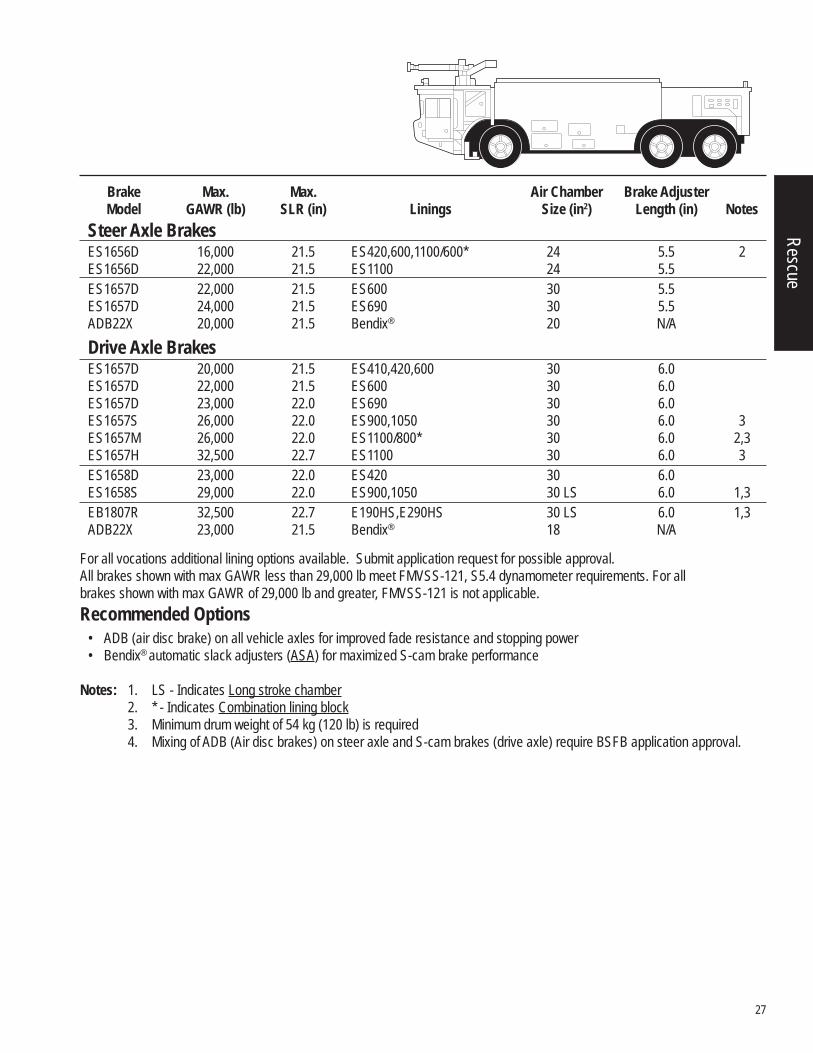
Rescue
27
For all vocations additional lining options available. Submit application request for possible approval.All brakes shown with max GAWR less than 29,000 lb meet FMVSS-121, S5.4 dynamometer requirements. For all brakes shown with max GAWR of 29,000 lb and greater, FMVSS-121 is not applicable.Recommended Options
• ADB (air disc brake) on all vehicle axles for improved fade resistance and stopping power • Bendix® automatic slack adjusters (ASA) for maximized S-cam brake performance
Notes: 1. LS - Indicates Long stroke chamber 2. * - Indicates Combination lining block 3. Minimum drum weight of 54 kg (120 lb) is required 4. Mixing of ADB (Air disc brakes) on steer axle and S-cam brakes (drive axle) require BSFB application approval.
Brake Max. Max. Air Chamber Brake Adjuster Model GAWR (lb) SLR (in) Linings Size (in2) Length (in) NotesSteer Axle Brakes
ES1656D 16,000 21.5 ES420,600,1100/600* 24 5.5 2 ES1656D 22,000 21.5 ES1100 24 5.5 ES1657D 22,000 21.5 ES600 30 5.5 ES1657D 24,000 21.5 ES690 30 5.5 ADB22X 20,000 21.5 Bendix® 20 N/ADrive Axle Brakes
ES1657D 20,000 21.5 ES410,420,600 30 6.0 ES1657D 22,000 21.5 ES600 30 6.0 ES1657D 23,000 22.0 ES690 30 6.0 ES1657S 26,000 22.0 ES900,1050 30 6.0 3 ES1657M 26,000 22.0 ES1100/800* 30 6.0 2,3 ES1657H 32,500 22.7 ES1100 30 6.0 3 ES1658D 23,000 22.0 ES420 30 6.0 ES1658S 29,000 22.0 ES900,1050 30 LS 6.0 1,3 EB1807R 32,500 22.7 E190HS,E290HS 30 LS 6.0 1,3 ADB22X 23,000 21.5 Bendix® 18 N/A
Rescue
28
Defi nitions Transporting students to and from school and/ or school related events Operation on road surfaces of concrete, asphalt, maintained gravel, crushed rock, or hard packed dirt Two (2) stops per mile are considered typical 100% load going / empty return (typical)
Typical Vehicle Types Front Engine Commercial Chassis Front Engine Integral Coach Rear Engine Integral Coach
Vehicle Confi gurations 4 x 2 straight bus
General Requirements • Anti-compounding air system • Cam same operation for all brakes • Air chamber bracket with gusset for all school bus applications, see page 45 • Air chamber bracket assembly gusset and additional camshaft bracket support see page 45, attached to the axle housing
when the: a. Brake centerline to air chamber centerline distance (BCCC dimension) is greater than 343 mm [13.5”] b. Application use a type 30/36 or 36/36 Spring brake chambers. c. Camshaft brackets with BCCC dimension of less than 8.12" does not require a gusset or additional support. d. Super Single Tire (Wide Base)Note: The above support can be supplied by BSFB or the vehicle manufacturer but
must be approved by BSFB Application Engineering Department.• Applications for use in countries other than the USA and Canada must be reviewed by BSFB Application Engineering. • Vehicle manufacturer is responsible for air system design, parking and stopping distance performance. • For all S-cam brake models the camshaft input torque is limited to 2545 N•m [22,500 in-lbs]. • Applications on vehicles with fi xed or liftable auxiliary axles (tag or pusher) must be approved on an individual basis by the
BSFB Application Engineering Department, as auxiliary axles may impact the braking performance of the vehicle. General Recommendations
• Dust shields for all applications • Use Auxiliary retarders per TMC RP636 • Brake drum / Rotor material specifi cation per SAE J431. Drum / rotor surface fi nish 4.57 micrometers [180 max microinch]
and .38 mm [.015"] runout, when mounted on a hub rotated on bearings. See notes section for Minimum Drum Weight requirements
• Brake air system balance per TMC RP632
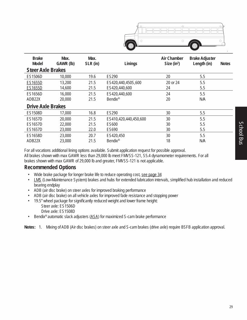
School Bus
29
For all vocations additional lining options available. Submit application request for possible approval.All brakes shown with max GAWR less than 29,000 lb meet FMVSS-121, S5.4 dynamometer requirements. For all brakes shown with max GAWR of 29,000 lb and greater, FMVSS-121 is not applicable.Recommended Options
• Wide brake package for longer brake life to reduce operating cost, see page 34 • LMS (Low-Maintenance System) brakes and hubs for extended lubrication intervals, simplifi ed hub installation and reduced
bearing endplay • ADB (air disc brake) on steer axles for improved braking performance • ADB (air disc brake) on all vehicle axles for improved fade resistance and stopping power • 19.5" wheel package for signifi cantly reduced weight and lower frame height:
Steer axle: ES1506DDrive axle: ES1508D
• Bendix® automatic slack adjusters (ASA) for maximized S-cam brake performance
Notes: 1. Mixing of ADB (Air disc brakes) on steer axle and S-cam brakes (drive axle) require BSFB application approval.
Brake Max. Max. Air Chamber Brake Adjuster Model GAWR (lb) SLR (in) Linings Size (in2) Length (in) NotesSteer Axle Brakes
ES1506D 10,000 19.6 ES290 20 5.5 ES1655D 13,200 21.5 ES420,440,450S,600 20 or 24 5.5 ES1655D 14,600 21.5 ES420,440,600 24 5.5 ES1656D 16,000 21.5 ES420,440,600 24 5.5 ADB22X 20,000 21.5 Bendix® 20 N/ADrive Axle Brakes
ES1508D 17,000 16.8 ES290 30 5.5 ES1657D 20,000 21.5 ES410,420,440,450,600 30 5.5 ES1657D 22,000 21.5 ES600 30 5.5 ES1657D 23,000 22.0 ES690 30 5.5 ES1658D 23,000 20.7 ES420,450 30 5.5 ADB22X 23,000 21.5 Bendix® 18 N/A
School Bus
30
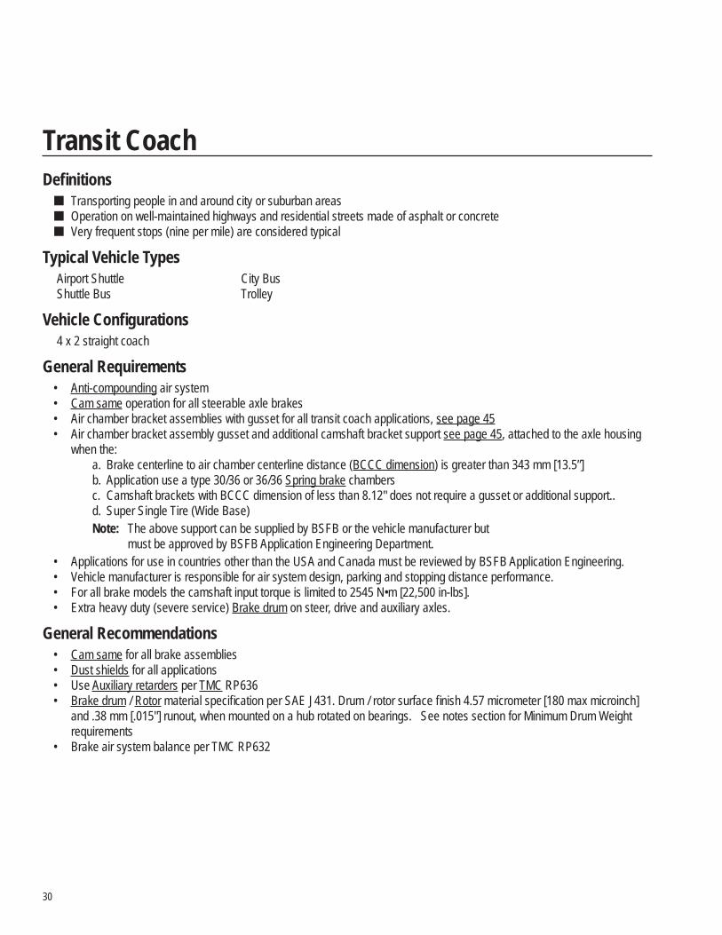
Defi nitions Transporting people in and around city or suburban areas Operation on well-maintained highways and residential streets made of asphalt or concrete Very frequent stops (nine per mile) are considered typical
Typical Vehicle Types Airport Shuttle City Bus Shuttle Bus Trolley
Vehicle Confi gurations 4 x 2 straight coach
General Requirements • Anti-compounding air system • Cam same operation for all steerable axle brakes • Air chamber bracket assemblies with gusset for all transit coach applications, see page 45 • Air chamber bracket assembly gusset and additional camshaft bracket support see page 45, attached to the axle housing
when the: a. Brake centerline to air chamber centerline distance (BCCC dimension) is greater than 343 mm [13.5”] b. Application use a type 30/36 or 36/36 Spring brake chambers c. Camshaft brackets with BCCC dimension of less than 8.12" does not require a gusset or additional support..d. Super Single Tire (Wide Base)Note: The above support can be supplied by BSFB or the vehicle manufacturer but
must be approved by BSFB Application Engineering Department.• Applications for use in countries other than the USA and Canada must be reviewed by BSFB Application Engineering. • Vehicle manufacturer is responsible for air system design, parking and stopping distance performance. • For all brake models the camshaft input torque is limited to 2545 N•m [22,500 in-lbs]. • Extra heavy duty (severe service) Brake drum on steer, drive and auxiliary axles.
General Recommendations • Cam same for all brake assemblies • Dust shields for all applications • Use Auxiliary retarders per TMC RP636 • Brake drum / Rotor material specifi cation per SAE J431. Drum / rotor surface fi nish 4.57 micrometer [180 max microinch]
and .38 mm [.015"] runout, when mounted on a hub rotated on bearings. See notes section for Minimum Drum Weight requirements
• Brake air system balance per TMC RP632
Transit Coach
31
For all vocations additional lining options available. Submit application request for possible approval.All brakes shown with max GAWR less than 29,000 lb meet FMVSS-121, S5.4 dynamometer requirements. For all brakes shown with max GAWR of 29,000 lb and greater, FMVSS-121 is not applicable.Recommended Options
• Bendix® automatic slack adjusters (ASA) for maximized S-cam brake performance
Notes: 1. LS - Indicates Long stroke chamber 2. * - Indicates Combination lining block 3. Minimum drum weight of 54 kg (120 lb) is required 4. Mixing of ADB (Air disc brakes) on steer axle and S-cam brakes (drive axle) require BSFB application approval.
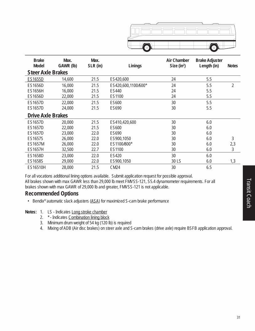
Brake Max. Max. Air Chamber Brake Adjuster Model GAWR (lb) SLR (in) Linings Size (in2) Length (in) NotesSteer Axle Brakes
ES1655D 14,600 21.5 ES420,600 24 5.5 ES1656D 16,000 21.5 ES420,600,1100/600* 24 5.5 2 ES1656H 16,000 21.5 ES440 24 5.5 ES1656D 22,000 21.5 ES1100 24 5.5 ES1657D 22,000 21.5 ES600 30 5.5 ES1657D 24,000 21.5 ES690 30 5.5Drive Axle Brakes
ES1657D 20,000 21.5 ES410,420,600 30 6.0 ES1657D 22,000 21.5 ES600 30 6.0 ES1657D 23,000 22.0 ES690 30 6.0 ES1657S 26,000 22.0 ES900,1050 30 6.0 3 ES1657M 26,000 22.0 ES1100/800* 30 6.0 2,3 ES1657H 32,500 22.7 ES1100 30 6.0 3 ES1658D 23,000 22.0 ES420 30 6.0 ES1658S 29,000 22.0 ES900,1050 30 LS 6.0 1,3 ES16510H 28,000 21.5 CM24 30 6.5
Transit Coach
32
EB – Standard BrakeES – Extended Service Brake
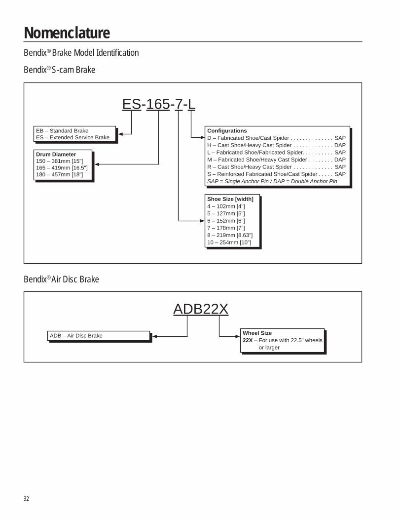
NomenclatureBendix® Brake Model Identifi cation
Bendix® S-cam Brake
Bendix® Air Disc Brake
ES-165-7-LEB – Standard BrakeES – Extended Service Brake
Drum Diameter150 – 381mm [15"]165 – 419mm [16.5"]180 – 457mm [18"]
Confi gurationsD – Fabricated Shoe/Cast Spider . . . . . . . . . . . . . . SAPH – Cast Shoe/Heavy Cast Spider . . . . . . . . . . . . . DAPL – Fabricated Shoe/Fabricated Spider. . . . . . . . . . SAPM – Fabricated Shoe/Heavy Cast Spider . . . . . . . . DAPR – Cast Shoe/Heavy Cast Spider . . . . . . . . . . . . . SAPS – Reinforced Fabricated Shoe/Cast Spider . . . . . SAPSAP = Single Anchor Pin / DAP = Double Anchor Pin
Shoe Size [width]4 – 102mm [4"]5 – 127mm [5"]6 – 152mm [6"]7 – 178mm [7"]8 – 219mm [8.63"]10 – 254mm [10"]
ADB22XADB – Air Disc Brake Wheel Size
22X – For use with 22.5" wheelsor larger
33
NomenclatureModel Coverage
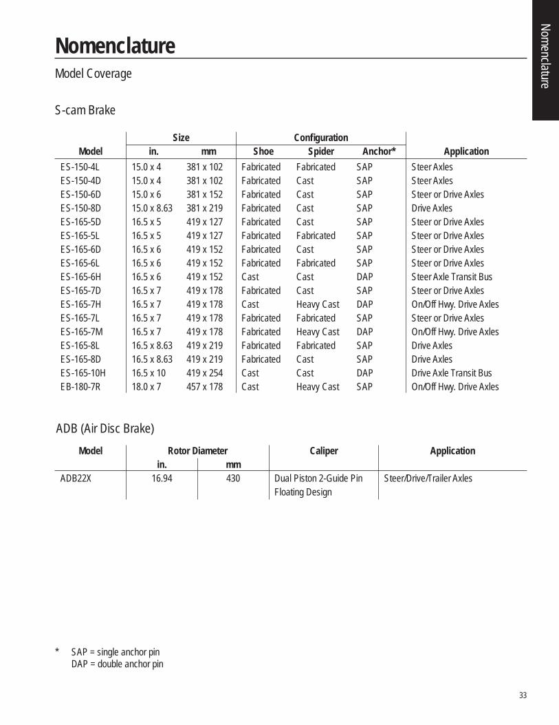
S-cam Brake
Size Confi guration Model in. mm Shoe Spider Anchor* Application ES-150-4L 15.0 x 4 381 x 102 Fabricated Fabricated SAP Steer Axles ES-150-4D 15.0 x 4 381 x 102 Fabricated Cast SAP Steer Axles ES-150-6D 15.0 x 6 381 x 152 Fabricated Cast SAP Steer or Drive Axles ES-150-8D 15.0 x 8.63 381 x 219 Fabricated Cast SAP Drive Axles ES-165-5D 16.5 x 5 419 x 127 Fabricated Cast SAP Steer or Drive Axles ES-165-5L 16.5 x 5 419 x 127 Fabricated Fabricated SAP Steer or Drive Axles ES-165-6D 16.5 x 6 419 x 152 Fabricated Cast SAP Steer or Drive Axles ES-165-6L 16.5 x 6 419 x 152 Fabricated Fabricated SAP Steer or Drive Axles ES-165-6H 16.5 x 6 419 x 152 Cast Cast DAP Steer Axle Transit Bus ES-165-7D 16.5 x 7 419 x 178 Fabricated Cast SAP Steer or Drive Axles ES-165-7H 16.5 x 7 419 x 178 Cast Heavy Cast DAP On/Off Hwy. Drive Axles ES-165-7L 16.5 x 7 419 x 178 Fabricated Fabricated SAP Steer or Drive Axles ES-165-7M 16.5 x 7 419 x 178 Fabricated Heavy Cast DAP On/Off Hwy. Drive Axles ES-165-8L 16.5 x 8.63 419 x 219 Fabricated Fabricated SAP Drive Axles ES-165-8D 16.5 x 8.63 419 x 219 Fabricated Cast SAP Drive Axles ES-165-10H 16.5 x 10 419 x 254 Cast Cast DAP Drive Axle Transit Bus EB-180-7R 18.0 x 7 457 x 178 Cast Heavy Cast SAP On/Off Hwy. Drive Axles
ADB (Air Disc Brake) Model Rotor Diameter Caliper Application in. mm ADB22X 16.94 430 Dual Piston 2-Guide Pin Steer/Drive/Trailer Axles Floating Design
* SAP = single anchor pin DAP = double anchor pin
Nomenclature
34
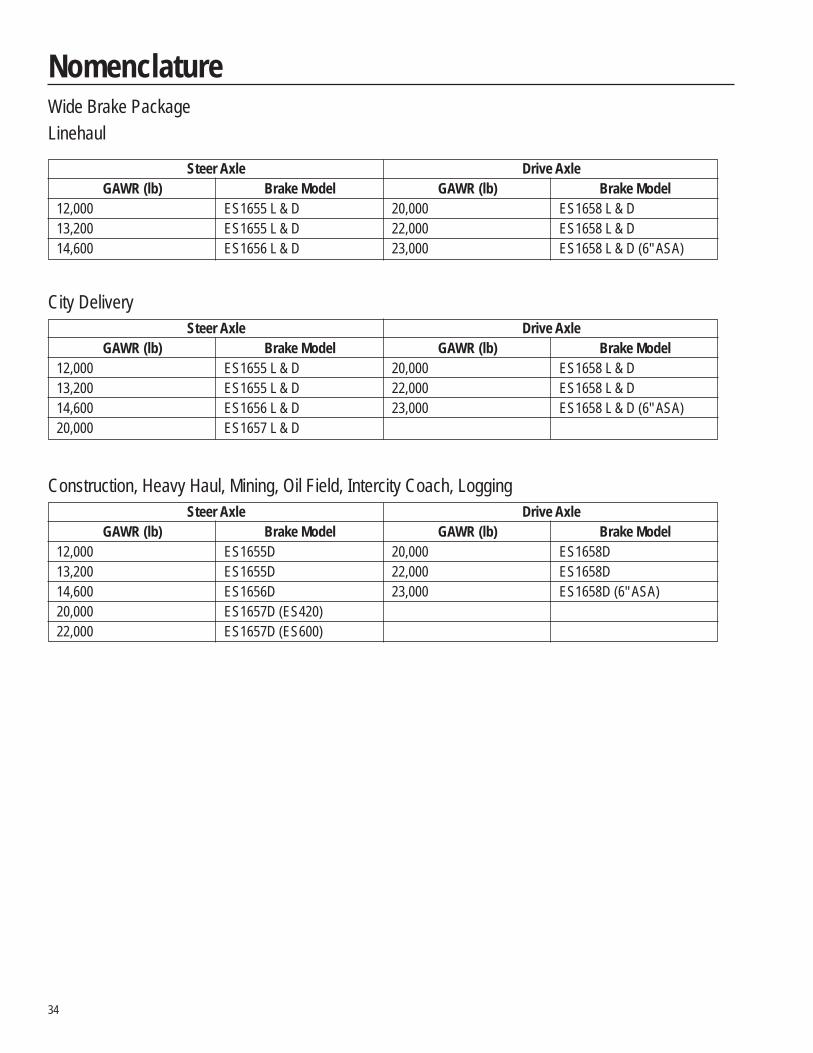
NomenclatureWide Brake PackageLinehaul
Steer Axle Drive Axle GAWR (lb) Brake Model GAWR (lb) Brake Model 12,000 ES1655 L & D 20,000 ES1658 L & D 13,200 ES1655 L & D 22,000 ES1658 L & D 14,600 ES1656 L & D 23,000 ES1658 L & D (6" ASA)
City Delivery Steer Axle Drive Axle GAWR (lb) Brake Model GAWR (lb) Brake Model 12,000 ES1655 L & D 20,000 ES1658 L & D 13,200 ES1655 L & D 22,000 ES1658 L & D 14,600 ES1656 L & D 23,000 ES1658 L & D (6" ASA) 20,000 ES1657 L & D
Construction, Heavy Haul, Mining, Oil Field, Intercity Coach, Logging Steer Axle Drive Axle GAWR (lb) Brake Model GAWR (lb) Brake Model 12,000 ES1655D 20,000 ES1658D 13,200 ES1655D 22,000 ES1658D 14,600 ES1656D 23,000 ES1658D (6" ASA) 20,000 ES1657D (ES420) 22,000 ES1657D (ES600)
35
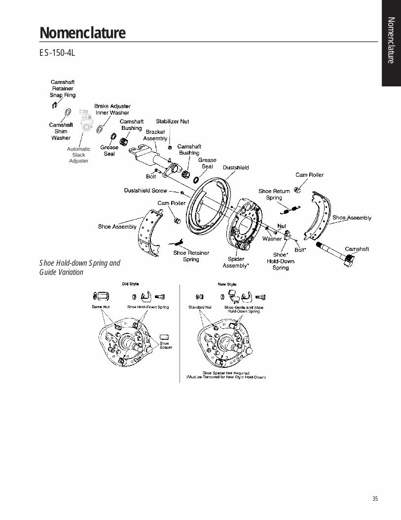
NomenclatureES-150-4L
Shoe Hold-down Spring andGuide Variation
AutomaticSlack
Adjuster
Nomenclature
36
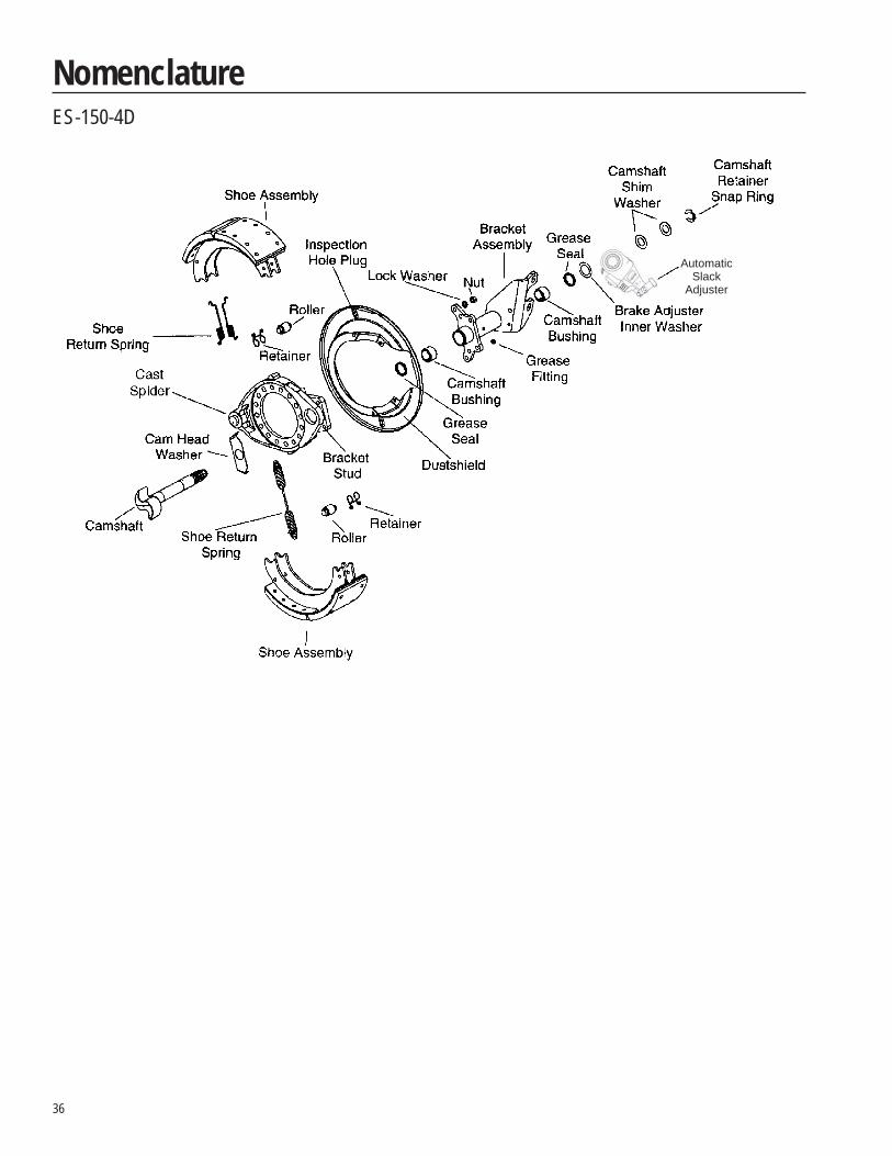
NomenclatureES-150-4D
AutomaticSlack
Adjuster
37
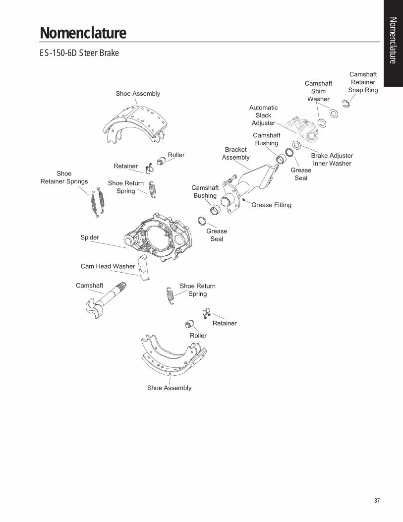
NomenclatureES-150-6D Steer Brake
Camshaft
Shoe Assembly
Shoe Assembly
Shoe ReturnSpring
Roller
Shoe ReturnSpring
Grease Fitting
Retainer
Roller
GreaseSeal
BracketAssembly
CamshaftBushing
Cam Head Washer
GreaseSeal
Brake AdjusterInner Washer
CamshaftShim
Washer
CamshaftRetainer
Snap Ring
Spider
RetainerShoe
Retainer Springs
AutomaticSlack
Adjuster
CamshaftBushing
Nomenclature
38
Camshaft
Shoe Assembly
Shoe Assembly
Roller
Shoe ReturnSpring
Grease Fitting
Retainer
Roller
GreaseSeal
BracketAssembly
CamshaftBushing
Cam Head Washer
GreaseSeal
Brake AdjusterInner Washer
CamshaftShim
Washer
CamshaftRetainer
Snap Ring
Spider
Retainer
ShoeRetainer Springs
Automatic Slack Adjuster
CamshaftBushing
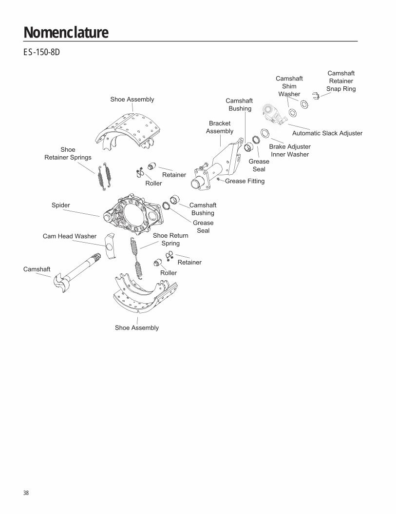
NomenclatureES-150-8D
39
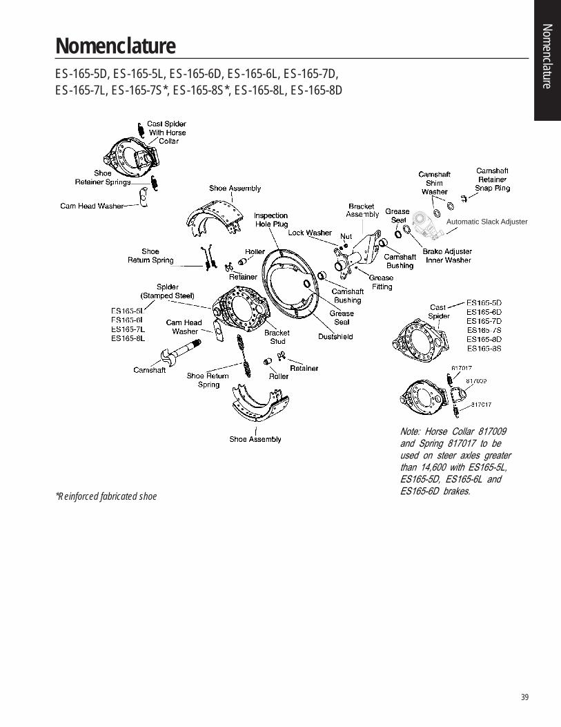
NomenclatureES-165-5D, ES-165-5L, ES-165-6D, ES-165-6L, ES-165-7D,ES-165-7L, ES-165-7S*, ES-165-8S*, ES-165-8L, ES-165-8D
Note: Horse Collar 817009 and Spring 817017 to be used on steer axles greater than 14,600 with ES165-5L, ES165-5D, ES165-6L and ES165-6D brakes.*Reinforced fabricated shoe
Automatic Slack Adjuster
Nomenclature
40
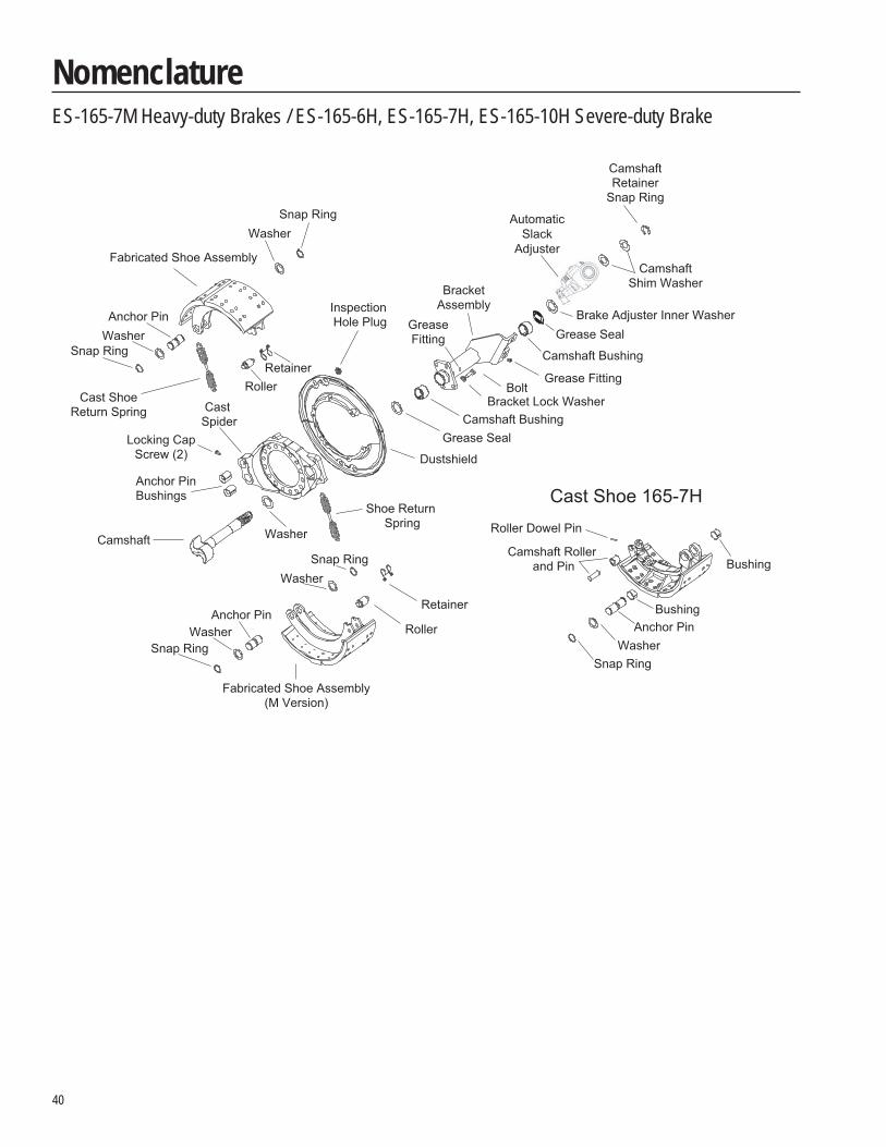
NomenclatureES-165-7M Heavy-duty Brakes / ES-165-6H, ES-165-7H, ES-165-10H Severe-duty Brake
Cast Shoe 165-7H
Camshaft
Shoe Return Spring
Grease Fitting
Retainer
Roller
Grease Seal
BracketAssembly
GreaseFitting
Camshaft Bushing
Grease Seal
Brake Adjuster Inner Washer
CamshaftShim Washer
CamshaftRetainer
Snap Ring
Cast Spider Camshaft Bushing
AutomaticSlack
Adjuster
Bracket Lock Washer
Fabricated Shoe Assembly
Fabricated Shoe Assembly(M Version)
Dustshield
Inspection Hole Plug
Cast ShoeReturn Spring
Bolt
WasherSnap Ring
Snap RingWasherAnchor Pin
RollerRetainer
Locking CapScrew (2)
Anchor PinBushings
Washer
WasherSnap Ring
Snap RingWasher
Anchor Pin
Bushing
Roller Dowel Pin
BushingAnchor Pin
WasherSnap Ring
Camshaft Roller and Pin
41
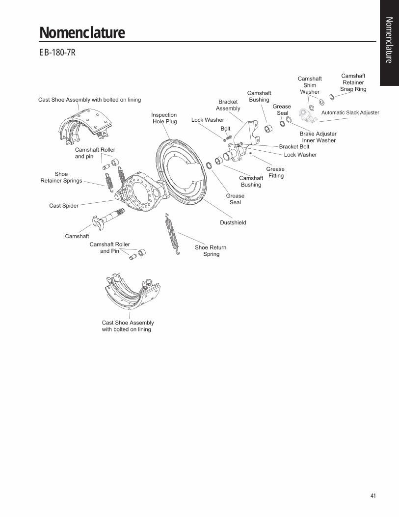
NomenclatureEB-180-7R
Camshaft
Cast Shoe Assembly with bolted on lining
Cast Shoe Assembly with bolted on lining
Camshaft Rollerand pin
Shoe Return Spring
Camshaft Rollerand Pin
Grease Seal
BracketAssembly
CamshaftBushing
GreaseSeal
Brake Adjuster Inner Washer
CamshaftShim
Washer
CamshaftRetainer
Snap Ring
Cast Spider
ShoeRetainer Springs
CamshaftBushing
Brake AdjusterInspection Hole Plug
Dustshield
Grease Fitting
Lock WasherBolt
Bracket BoltLock Washer
Nomenclature
Automatic Slack Adjuster
42
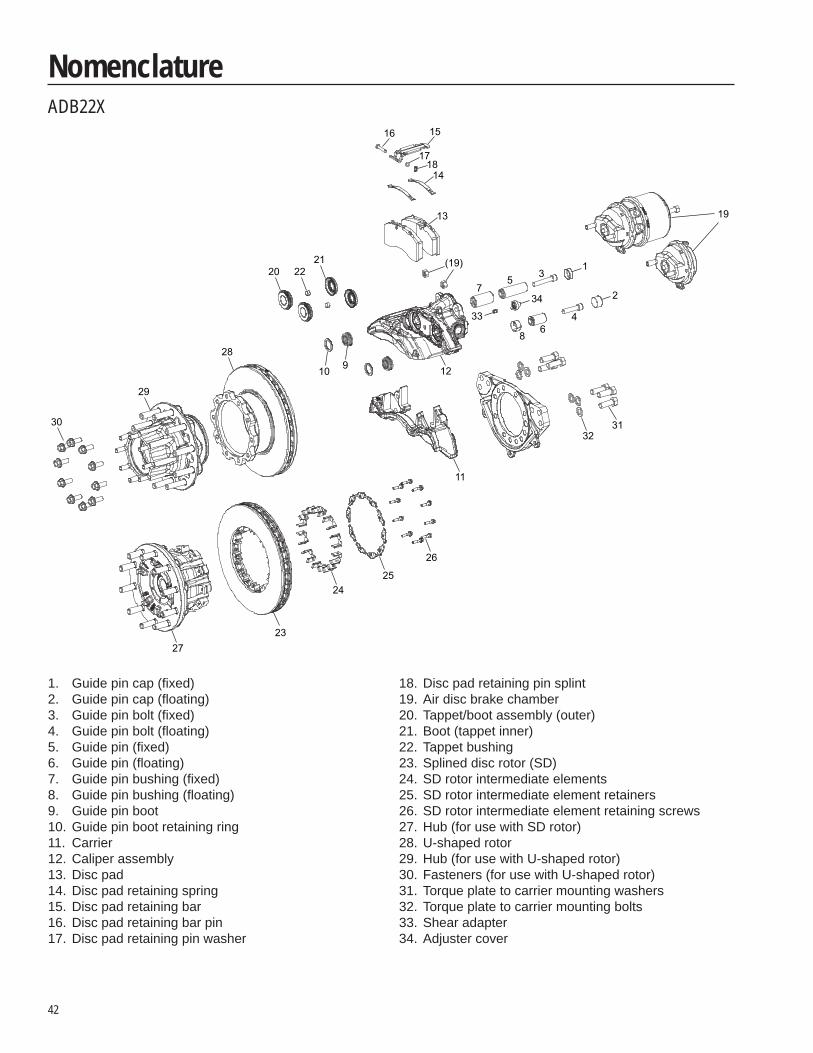
NomenclatureADB22X
1. Guide pin cap (fi xed)2. Guide pin cap (fl oating)3. Guide pin bolt (fi xed)4. Guide pin bolt (fl oating)5. Guide pin (fi xed)6. Guide pin (fl oating)7. Guide pin bushing (fi xed)8. Guide pin bushing (fl oating)9. Guide pin boot10. Guide pin boot retaining ring11. Carrier12. Caliper assembly13. Disc pad14. Disc pad retaining spring15. Disc pad retaining bar16. Disc pad retaining bar pin17. Disc pad retaining pin washer
18. Disc pad retaining pin splint19. Air disc brake chamber20. Tappet/boot assembly (outer)21. Boot (tappet inner)22. Tappet bushing23. Splined disc rotor (SD)24. SD rotor intermediate elements25. SD rotor intermediate element retainers26. SD rotor intermediate element retaining screws27. Hub (for use with SD rotor)28. U-shaped rotor29. Hub (for use with U-shaped rotor)30. Fasteners (for use with U-shaped rotor)31. Torque plate to carrier mounting washers32. Torque plate to carrier mounting bolts33. Shear adapter34. Adjuster cover
16 15
1718
14
13
(19)
19
75 3
1
33
34
4
2
68
12
3132
11
26
2524
2327
30
29
28910
212220
43
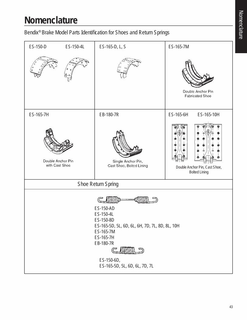
NomenclatureBendix® Brake Model Parts Identifi cation for Shoes and Return Springs
ES-150-D ES-150-4L ES-165-D, L, S ES-165-7M
ES-165-7H EB-180-7R ES-165-6H ES-165-10H
Shoe Return Spring
ES-150-ADES-150-4LES-150-8DES-165-5D, 5L, 6D, 6L, 6H, 7D, 7L, 8D, 8L, 10HES-165-7MES-165-7HEB-180-7R
ES-150-6D,ES-165-5D, 5L, 6D, 6L, 7D, 7L
Double Anchor Pin, Cast Shoe,Bolted Lining
Nomenclature
44
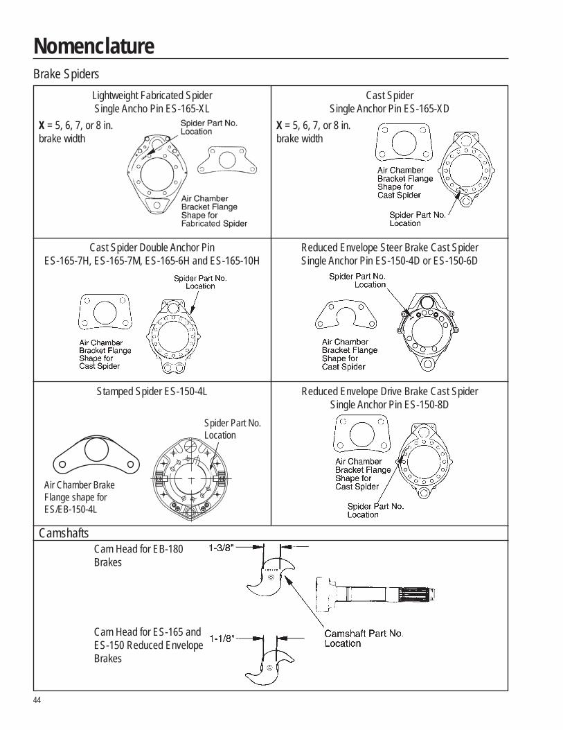
NomenclatureBrake Spiders
Lightweight Fabricated SpiderSingle Ancho Pin ES-165-XL
X = 5, 6, 7, or 8 in.brake width
Camshafts
Cast SpiderSingle Anchor Pin ES-165-XD
X = 5, 6, 7, or 8 in.brake width
Cast Spider Double Anchor PinES-165-7H, ES-165-7M, ES-165-6H and ES-165-10H
Reduced Envelope Steer Brake Cast SpiderSingle Anchor Pin ES-150-4D or ES-150-6D
Stamped Spider ES-150-4L Reduced Envelope Drive Brake Cast SpiderSingle Anchor Pin ES-150-8D
Cam Head for EB-180Brakes
Cam Head for ES-165 andES-150 Reduced EnvelopeBrakes
Spider Part No.Location
Air Chamber BrakeFlange shape forES/EB-150-4L
45
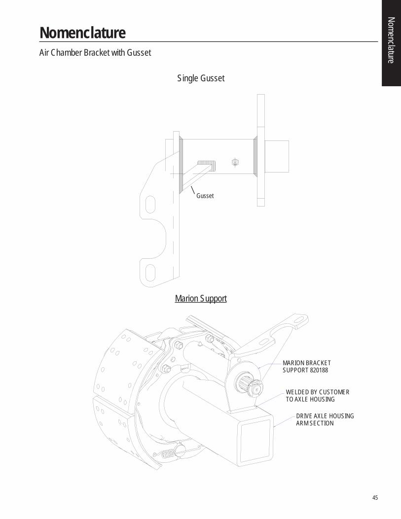
NomenclatureAir Chamber Bracket with Gusset
Single Gusset
Marion Support
Gusset
MARION BRACKETSUPPORT 820188
WELDED BY CUSTOMERTO AXLE HOUSING
DRIVE AXLE HOUSINGARM SECTION
Nomenclature

BW7260 ©2008 Bendix Spicer Foundation Brake LLC • 02/08 • All Rights Reserved • Printed in U.S.A.
901 Cleveland Street • Elyria, Ohio 44035 • 1-866-610-9709 • www.foundationbrakes.com
The Roadranger® System featuresBendix® brand foundation brakes.
FFoorr mmoorree iinnffoorrmmaattiioonn,, ttaallkk ttoo yyoouurr BBeennddiixx oorr RRooaaddrraannggeerrrreepprreesseennttaattiivvee,, ccaallll 11--886666--661100--99770099 oorr vviissiitt
wwwwww..ffoouunnddaattiioonnbbrraakkeess..ccoomm..
Recommended