INS531-4
Premier Elite 12-W/24-W/48-WQuick Start Guide

Premier Elite 12-W/24-W/48-W Quick Start Guide
2 INS531-4
Introduction
Texecom has developed a new method of wireless security signalling based on the concept of mesh networking. Mesh-networking is the process whereby every single wireless device is capable of receiving and retransmitting any signal from any other wireless device on the network. The size, scalability and range of the entire system are extended as wireless signalling is no longer limited by point-to point communications. The range of a Ricochet® enabled wireless system is greater than previous systems, with multiple devices capable of relaying messages to and from even the most remote locations in a building. Each Ricochet enabled device provides signalling routes to and from Premier control panels. If the wireless communication between devices weakens, the Ricochet network ‘self-heals’ and automatically re-routes communications via alternate Ricochet enabled devices. The reliability of the wireless system increases as more Ricochet devices are installed. SignalSecurity™ further enhances network reliability with each device already aware of the number of communication paths available to it.
System Design Considerations
To ensure correct setup and operation of the Wireless Network it is important that the following procedures are used when learning and placing devices.
Learning Devices All devices should be learnt before they are placed in their final location. The expander should be in commission mode, (see page 5). This will ensure that they are registered on the receiver or control panel, and that Mesh Networks and routing are established correctly. Please refer to the relevant section in this document to Learn Devices to the system.
Devices should be at least 30cm’s away from the receiver when being learned.
Placing Devices Once all of the devices have been learnt, they will need placing in their desired location, this should be done by installing devices closest to the Premier 48-W first and then working outwards so that the last devices installed are those furthest away from the control panel.
Make sure to install devices with the receiver in Commission mode. (fit commission jumper see page 5).
Devices also have a commission mode which will indicate a secure and valid path of communication to the receiver. (when the tamper circuit is closed the LED will flash to indicate communication, and then come on solid once communication has been established).
You should wait at least 20 minutes after installing the last device to make sure routing has been correctly established between all system devices.
For maximum reliability and system integrity avoid long and thin set-ups.
Devices are capable of hopping through up to two other devices, or a maximum of three hops.
System Overview
System Architecture
3 or 8 Progra mmable 10 0mA Outputs
Bell Ta mper Input
4 Zones
1 or 2 Programmable A )
Outputs(2 x 500 m P re mier Elite
12/24/48-W
Pre mier LC D/LC DP Pre mie r LC DL /LC DLPPre mier E lite LC DL P
4 Wire Data Network 1
16 Programmable10 0mA Outputs
2 ( 12 -W ) o r 4 ( 24-W /48-W ) K e ypa ds
Premier Elite OP 16
1 (24 -W ) o r 2 (48 -W ) O utpu t M odu le s
Alarm R eceivingCentre
Modem
PC and Modem for R emote Upload/Download
P C/USB -C om
PC and forLocal Uploa d/Download
PC/US B-C om
Plug on Digimode m
Plug on(C om300 or C om2400 )
Ra dio-Pa d,GS M Module
2 ZoneInputs
1 Programmable10 0mA Output
2 ZoneInputs
1 Programmable10 0mA Output
S pea kerOutput S pe aker Output
8 Zone Inputs
Auxiliary Input
Premie r Elite 8XP
8 Programmable 10 0mA Outputs
2(2 4-W) or 3(4 8-W) on ly E xpan der s
4 to 4 8 Zo n es8 -32 W ir eles s D evic e s lo ts
Be ll/S trobe Outputs
8 or 32 De vice Wi rele ss R ec eiv er
S pe aker Output
Auxiliary Ta mper Input
Premier Elite 12-W/24-W/48-W Quick Start Guide
INS531-4 3
Control Panel Features
Premier Elite 12-W/24-W/48-W
• 4 Onboard Zones
• Max 8,16 or 32 wireless device Ricochet enabled receiver onboard
• Expandable to 12-48 zones via keypads and zone expanders
• 1 x 4-wire data network (standard 7/0.2 alarm cable)
• Up to 4 keypads (2 only on the 12-W) and 0-3 zone expanders
• Up to 2 output modules (0 on 12-W)
• 2 or 4 independent areas each with 3 part arms
• 2 or 4 area arm suites
• 8 (12-W), 25 (24-W), or 50 (48-W), programmable User codes
• 250 (12-W) or 500 (24-W/48-W) Event Log (time & date stamped)
• 1 or 2 programmable panel outputs (2 x 500mA )
• 1.5 Amp power supply
• 32 Event Alarm Log
• 3 or 8 programmable digicom outputs (100mA each)
• 32 character zone text
• Facility for Plug-on Digimodem (Com300/2400/)
• Facility for Plug-on GSM Module
• Facility for Plug-on IP Module (ComIP/Chiron/WebWayOne/Emizon) or any supported device
• PC-Com/printer port
Power Supply Ratings Battery
Arrangement Battery Charge
Rated Output (Amps) 12h
1 x 7Ah 0.3A 0.433A
The “Rated Power” of the control panel will depend on the size of the standby battery, standby time and the installation grade:
EN50131-1 Grade 1 Grade 2 Minimum Standby Period 12h 12h Maximum Recharge Time 72 Hrs 72 Hrs
PD6662 Grade 1 Grade 2 Standby Period 12 Hrs 12 Hrs
Maximum Recharge Time 72 Hrs 72 Hrs
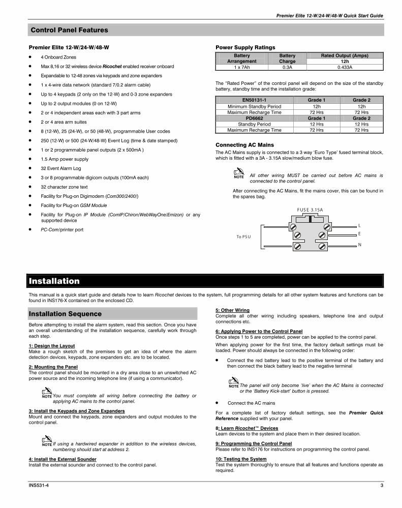
Connecting AC Mains The AC Mains supply is connected to a 3 way ‘Euro Type’ fused terminal block, which is fitted with a 3A - 3.15A slow/medium blow fuse.
All other wiring MUST be carried out before AC mains is connected to the control panel.
After connecting the AC Mains, fit the mains cover, this can be found in the spares bag.
L
E
N
To PS U
F US E 3.15A
Installation
This manual is a quick start guide and details how to learn Ricochet devices to the system, full programming details for all other system features and functions can be found in INS176-X contained on the enclosed CD.
Installation Sequence
Before attempting to install the alarm system, read this section. Once you have an overall understanding of the installation sequence, carefully work through each step.
1: Design the Layout Make a rough sketch of the premises to get an idea of where the alarm detection devices, keypads, zone expanders etc. are to be located.
2: Mounting the Panel The control panel should be mounted in a dry area close to an unswitched AC power source and the incoming telephone line (if using a communicator).
You must complete all wiring before connecting the battery or applying AC mains to the control panel.
3: Install the Keypads and Zone Expanders Mount and connect the keypads, zone expanders and output modules to the control panel.
If using a hardwired expander in addition to the wireless devices, numbering should start at address 2.
4: Install the External Sounder Install the external sounder and connect to the control panel.
5: Other Wiring Complete all other wiring including speakers, telephone line and output connections etc.
6: Applying Power to the Control Panel Once steps 1 to 5 are completed, power can be applied to the control panel.
When applying power for the first time, the factory default settings must be loaded. Power should always be connected in the following order:
• Connect the red battery lead to the positive terminal of the battery and then connect the black battery lead to the negative terminal
The panel will only become ‘live’ when the AC Mains is connected or the ‘Battery Kick-start’ button is pressed.
• Connect the AC mains
For a complete list of factory default settings, see the Premier Quick Reference supplied with your panel.
8: Learn Ricochet™ Devices Learn devices to the system and place them in their desired location.
9: Programming the Control Panel Please refer to INS176 for instructions on programming the control panel.
10: Testing the System Test the system thoroughly to ensure that all features and functions operate as required.
Premier Elite 12-W/24-W/48-W Quick Start Guide
4 INS531-4
Control Panel
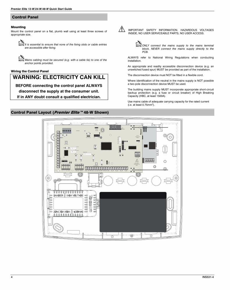
Mounting Mount the control panel on a flat, plumb wall using at least three screws of appropriate size.
It is essential to ensure that none of the fixing slots or cable entries are accessible after fixing.
Mains cabling must be secured (e.g. with a cable tie) to one of the anchor points provided.
Wiring the Control Panel
WARNING: ELECTRICITY CAN KILL BEFORE connecting the control panel ALWAYS
disconnect the supply at the consumer unit. If in ANY doubt consult a qualified electrician.
IMPORTANT SAFETY INFORMATION. HAZARDOUS VOLTAGES INSIDE, NO USER SERVICEABLE PARTS, NO USER ACCESS.
ONLY connect the mains supply to the mains terminal block, NEVER connect the mains supply directly to the PCB.
ALWAYS refer to National Wiring Regulations when conducting installation.
An appropriate and readily accessible disconnection device (e.g. an unswitched fused spur) MUST be provided as part of the installation.
The disconnection device must NOT be fitted in a flexible cord.
Where identification of the neutral in the mains supply is NOT possible a two-pole disconnection device MUST be used.
The building mains supply MUST incorporate appropriate short-circuit backup protection (e.g. a fuse or circuit breaker) of High Breaking Capacity (HBC, at least 1500A).
Use mains cable of adequate carrying capacity for the rated current (i.e. at least 0.75mm2).
Control Panel Layout (Premier Elite™ 48-W Shown)
TRT1R1
Audio
Com
1
OP 1-Tamp S pk+ S pk-+ 12vB ell0V OP 2-AU X Fau ltS trb
DC
+L/M
R/R
DC
-
2
3
5
6
7
8
4
1
+B
att-
+ - T R AUX 0 VAUX 1 2V
Load Defau lts
Jp
1
J p7
Fit forC om mis s ion
Mode
DigiMo dem
Ric
oc
he
t M
on
ito
r
J p2 LE D1
Dig
ico
m O
/P’s
Tx R x
Tx R x
Wir
ele
ss
En
g K
pd
J p6
J p4
C o m 1
J p3C o m 2
J p9
K ic k S tart
E xp ans ion
Network Aux 12V B ell 12V
En
ab
leS
mo
ke
E ngin eer R E M
1
ON
2 43O P TIO NS
Tam perDis ab leV
F3
F4 F5 F6
F1F8 B a tt C har ge
0. 75A 0. 3A
F 2
!
BAR CODE
US E WIT HTE XE C OM P S U
ON LY
Z1 Z2 Z3 Z4
F7
Premier Elite 12-W/24-W/48-W Quick Start Guide
INS531-4 5
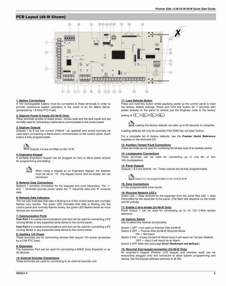
PCB Layout (48-W Shown)
1: Battery Connections A 12V rechargeable battery must be connected to these terminals in order to provide continuous system operation in the event of an AC Mains failure. (protected by 1.6 Amp PTC Fuse)
2: Digicom Power & Inputs (24/48-W Only) These terminals provide un-fused power; remote reset and line fault inputs and are normally used for connecting a stand-alone communicator to the control panel.
3: Digicom Outputs Outputs 1 to 8 are low current (100mA ‘-ve’ applied) and would normally be used when connecting a stand-alone communicator to the control panel. Each output is fully programmable.
Outputs 4-8 are not fitted on the 12-W
4: Engineers Keypad A portable Engineers keypad can be plugged on here to allow easier access for programming and testing.
When using a keypad as an Engineers keypad, the address must be set to ‘10’. The keypad zones and lid tamper are not monitored.
5: Network Data Connections Network 1 provides connection for the keypads and zone expanders. The ‘+’ and ‘–’ terminals provide power whilst the ‘T’ transmits data and ‘R’ receives data.
6: Network Data Indicators The red LED indicates that data is flowing out of the control panel and normally flashes very quickly. The green LED indicates that data is flowing into the control panel and normally flashes slowly, the green LED flashes faster as more devices are connected.
7: Communication Ports Com Port 1 is a serial communications port and can be used for connecting a PC running Wintex or any supported serial device to the control panel.
Com Port 2 is a serial communications port and can be used for connecting a PC running Wintex or any supported serial device to the control panel.
8: Auxiliary 12V Power These terminals are for connecting devices that require 12V power (protected by a 0.9A PTC fuse).
9: Expansion The Expansion Port can be used for connecting a 60XiD Zone Expander or an AV Module.
10: External Sounder Connections These terminals are used for connecting to an external sounder unit.
11: Load Defaults Button Press and hold this button whilst applying power to the control panel to load the factory default settings. Press and hold this button for 7 seconds with power already on the panel to restore just the Engineer code to the factory
setting of .
Loading the factory defaults can take up to 60 seconds to complete.
Loading defaults will only be possible if the NVM has not been locked.
For a complete list of factory defaults, see the Premier Quick Reference supplied on the enclosed CD.
12: Auxiliary Tamper/Fault Connections These terminals can be used for monitoring the tamper loop of an auxiliary device.
13: Loudspeaker Connections These terminals can be used for connecting up to one 8Ω or two 16Ω loudspeakers.
14: Panel Outputs Outputs 1 & 2 are 500mA ‘-ve’. These outputs are all fully programmable.
Output 2 is not programmable on the 12-W & 24-W
15: Zone Connections 4 Fully programmable zone inputs
16: Ricochet Network LED’s Green LED = Data received by the expander from the panel Red LED = Data transmitted by the expander to the panel. (The flash rate depends on the mode and RF activity)
17: Enable 2 wire smoke (24/48-W Only) Panel Output 1 can be used for connecting up to 10, 12V 2-Wire smoke detectors.
18: Options Switch Use to select the receiver functionality.
Switch 1 OFF =not used on Premier Elite 24/48-W. Switch 2 OFF = Premier Elite 24/48-W Ricochet Mode
ON = Not Used Switch 3 ON = Impaq Contact-W Wired Input 2 will report as Tamper (default)
OFF = input 2 will report as an Alarm. Switch 4 OFF Walk test (see page Error! Bookmark not defined.)
19: Ricochet Eng keypad connection (24/48-W Only) An engineer’s keypad (Premier LCD keypad and interface lead) can be temporarily plugged onto this connector to allow system programming and testing. Set the keypad address switches to all ON.
1
2
3
5 8 10 12 13 14
22
18
21
7 15
20
19
2324252627293033 31
E ngineer R E M
OP T IO NS
TamperDis able100mV = 1 AmpV
F 3
F 4 F 5 F 6
F 1F 8 B att C harge
0.75A 0.3A
F2
!
B AR C ODE
US E WIT HT E XE C O M P S U
O NLYF 7
32
6 16114
17
28
Premier Elite 12-W/24-W/48-W Quick Start Guide
6 INS531-4
20: Ricochet Firmware Flash Port Connections for flasher interface to update Ricochet receiver firmware.( factory function only)
21: Commission Mode Jumper Fit when learning and placing devices, remove once complete.
22: Antenna RF antenna (1 on 12-W/24-W 2 on 48-W)
23: RF LED’s Left = RED Transmit, Middle = GREEN Receive, Right = RED Wireless Network Tick.
24: Plug-on Communicator Connections This socket provides connection for Premier COM300/COM2400 plug-on communicators via the lead provided.
25: Ricochet Comm. Port Connection (24/48-W Only) Serial communications port for connecting to a PC via PC Com/USB Com or Com IP for use with Ricochet Monitor Software.
26: Cover Tamper Provides tamper protection for the control panel.
27: Heartbeat LED/Power Light Flashes steadily to indicate that the control panel is functioning correctly. If the light is ON or OFF all the time, then there could be a problem.
28: Cover Tamper Disable Disables the lid tamper
29: Flash Programming Port For upgrading the panel firmware.
30: Battery Charge Selection(24/48-W Only) Select .03A or 0.75A battery charging current
31: Current Reading Pads To calculate the current draw of the control panel, measure the voltage across the two pads and multiply by 10 i.e. Reading = 34mV (x10) = 340mV = 340mA.
32: Battery Kick-start Button When powering up the panel without AC Mains present, this button must be pressed in order to connect the battery. If AC Mains is present this button does not need to be pressed. 33: Power Supply Connection Only for use with the Texecom PSU. DO NOT CONNECT ANY OTHER MAINS SUPPLY TO THESE TERMINALS
PTC Protection Fuses The following fuses are provided:
F6 PTC (0.9A) Auxiliary 12V Power fuse
F4 PTC (0.9 A) Network 1 fuse F5 PTC (0.9 A) Bell/Strobe fuse
Ricochet V2.xx
Multiple Expander Support It is now possible to add multiple expanders to the system allowing for greater flexibility in system design, and also taking wireless capability to new levels. Additional device modes and diagnostics functions also give more information about the system status, and allow greater control over devices modes of operation.
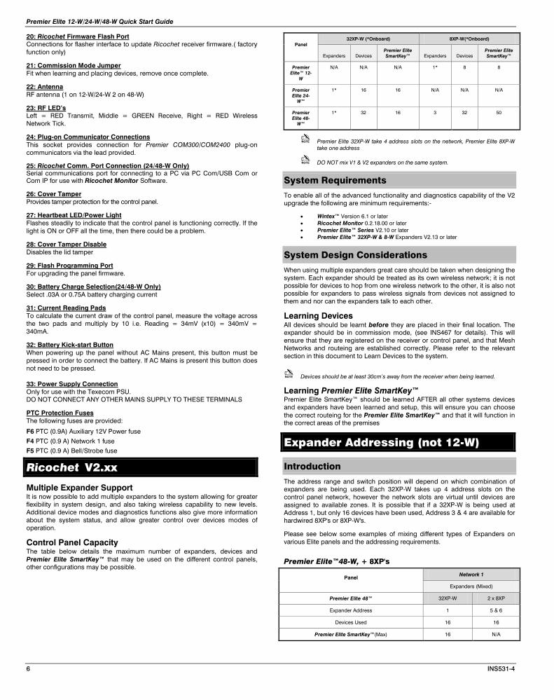
Control Panel Capacity The table below details the maximum number of expanders, devices and Premier Elite SmartKey™ that may be used on the different control panels, other configurations may be possible.
Panel 32XP-W (*Onboard) 8XP-W(*Onboard)
Expanders Devices Premier Elite SmartKey™ Expanders Devices
Premier Elite SmartKey™
Premier Elite™ 12-
W
N/A N/A N/A 1* 8 8
Premier Elite 24-
W™
1* 16 16 N/A N/A N/A
Premier Elite 48-
W™
1* 32 16 3 32 50
Premier Elite 32XP-W take 4 address slots on the network, Premier Elite 8XP-W take one address
DO NOT mix V1 & V2 expanders on the same system.
System Requirements
To enable all of the advanced functionality and diagnostics capability of the V2 upgrade the following are minimum requirements:-
• Wintex™ Version 6.1 or later • Ricochet Monitor 0.2.18.00 or later • Premier Elite™ Series V2.10 or later • Premier Elite™ 32XP-W & 8-W Expanders V2.13 or later
System Design Considerations
When using multiple expanders great care should be taken when designing the system. Each expander should be treated as its own wireless network; it is not possible for devices to hop from one wireless network to the other, it is also not possible for expanders to pass wireless signals from devices not assigned to them and nor can the expanders talk to each other.
Learning Devices All devices should be learnt before they are placed in their final location. The expander should be in commission mode, (see INS467 for details). This will ensure that they are registered on the receiver or control panel, and that Mesh Networks and routeing are established correctly. Please refer to the relevant section in this document to Learn Devices to the system.
Devices should be at least 30cm’s away from the receiver when being learned.
Learning Premier Elite SmartKey™ Premier Elite SmartKey™ should be learned AFTER all other systems devices and expanders have been learned and setup, this will ensure you can choose the correct routeing for the Premier Elite SmartKey™ and that it will function in the correct areas of the premises
Expander Addressing (not 12-W)
Introduction
The address range and switch position will depend on which combination of expanders are being used. Each 32XP-W takes up 4 address slots on the control panel network, however the network slots are virtual until devices are assigned to available zones. It is possible that if a 32XP-W is being used at Address 1, but only 16 devices have been used, Address 3 & 4 are available for hardwired 8XP's or 8XP-W's.
Please see below some examples of mixing different types of Expanders on various Elite panels and the addressing requirements.
Premier Elite™48-W, + 8XP's
Panel Network 1
Expanders (Mixed)
Premier Elite 48™ 32XP-W 2 x 8XP
Expander Address 1 5 & 6
Devices Used 16 16
Premier Elite SmartKey™(Max) 16 N/A
Premier Elite 12-W/24-W/48-W Quick Start Guide
INS531-4 7
Devices
Introduction
Learn Devices from first power up Follow the instructions given in INS176-8 or later for the first power up of the system.
When the "Confirm Devices" menu appears check and make sure all installed
Keypads and Expanders are showing; press / and
/ again to confirm.
Providing the system has a Ricochet enabled expander installed, the following will appear. The flow diagram shows the procedure to learn devices:-
YES to Select:-
Learn Ricochet
/
Learn Device?
Zone ??? N?,E??
Power up Device!
N?, E?, D?? - 20s
Learn Device to
Zone ??? N?,E??
The bottom line of text showsthe one number, the etwork
and the xpander the device willbe learned too.
Z NE
The bottom line of text showsthe etwork the xpander and
the device s lot on the expander.N E
/
/
/
Use the / or to select different zones . It is onlyposs ible to selec t Zones which
are free.
nn U
N/N
Access the Learn Menu using the Omit “Hot” key
From any top level engineering menu pressing the /key will
take you to the Ricochet learn menu above.
Menu / Ricochet Learn Menu
YES to Select:-
???????????????? / YES to Select:-
Learn Ricochet
IMPORTANT In all cases when entering the Learn menu the next available free Zone will be chosen to learn a device too. It will not be possible to learn a device to a Zone that already has a device learned too it. The number of expander’s on the system will dictate which next “free” zone is chosen to learn too.
When all device slots have been used the following screen will be shown
All Devices
Learnt!
Pressing the N/Nkey will return you to the Ricochet
learn menu; pressing the /key will enter the Delete devices
menu.
Auto Zone Type & Area
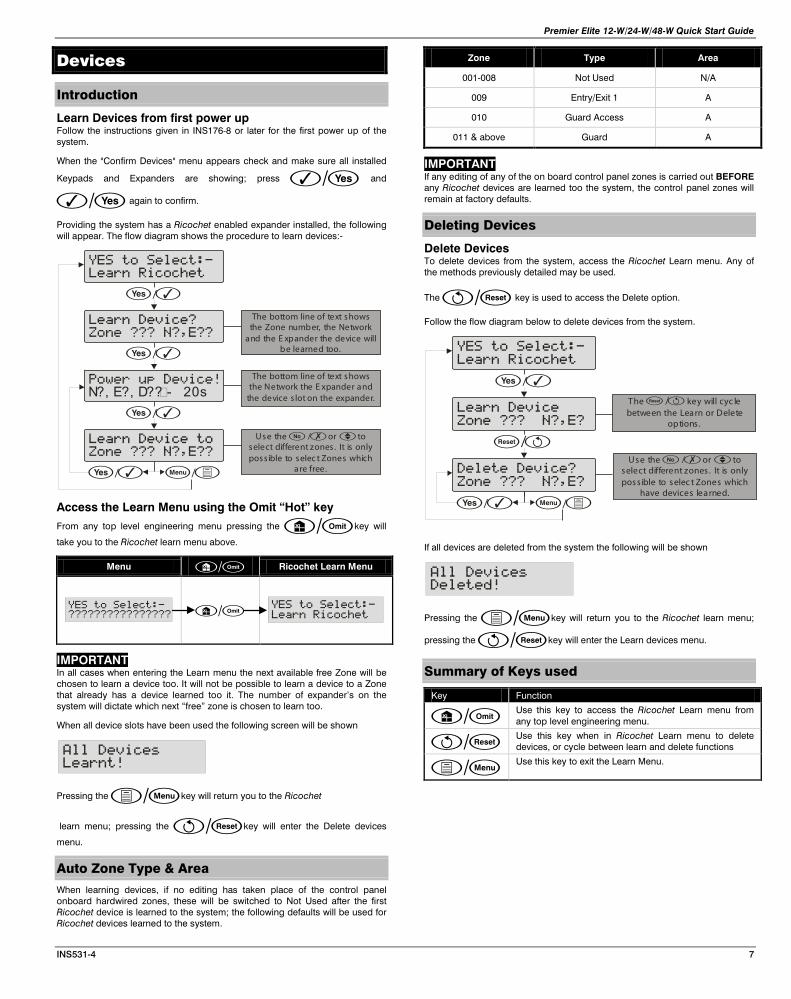
When learning devices, if no editing has taken place of the control panel onboard hardwired zones, these will be switched to Not Used after the first Ricochet device is learned to the system; the following defaults will be used for Ricochet devices learned to the system.
Zone Type Area
001-008 Not Used N/A
009 Entry/Exit 1 A
010 Guard Access A
011 & above Guard A
IMPORTANT If any editing of any of the on board control panel zones is carried out BEFORE any Ricochet devices are learned too the system, the control panel zones will remain at factory defaults.
Deleting Devices
Delete Devices To delete devices from the system, access the Ricochet Learn menu. Any of the methods previously detailed may be used.
The / key is used to access the Delete option.
Follow the flow diagram below to delete devices from the system.
YES to Select:-
Learn Ricochet
/
Learn Device
Zone ??? N?,E?
Delete Device?
Zone ??? N?,E?
Use the / or to select different zones . It is onlyposs ible to selec t Zones which
have devices learned.
nn U
The / key will cyc lebetween the Learn or Delete
options .
/
N/N/
If all devices are deleted from the system the following will be shown
All Devices
Deleted!
Pressing the N/Nkey will return you to the Ricochet learn menu;
pressing the /key will enter the Learn devices menu.
Summary of Keys used
Key Function
/ Use this key to access the Ricochet Learn menu from any top level engineering menu.
/ Use this key when in Ricochet Learn menu to delete devices, or cycle between learn and delete functions
N/N Use this key to exit the Learn Menu.

Premier Elite 12-W/24-W/48-W Quick Start Guide
8 INS531-4
Premier Elite SmartKey™
Introduction
Premier Elite SmartKey™ are learnt and all functionality managed through the “Setup Users” Menu.
In multiple expander systems it is now possible to choose which zones (and therefore expander) the Premier Elite SmartKey™ will use for its routeing, LED and Aux functions can also be changed within the “Setup Users” menu.
All users on the system can have a Premier Elite SmartKey™ a TAG and a code, or any combination of them.
All other user programmable options can be found in INS176-8 or later Premier Elite Series Installation Manual.
Great care should be taken when using large numbers of Premier Elite SmartKey™, only one Premier Elite SmartKey™ per expander can be used by the system at any one time, and on Multiple expanders systems, or large sites, functionality should be checked in all areas of the site where the device may be used.
Premier Elite SmartKey™ Routeing Premier Elite SmartKey™ should only be learned to the system AFTER all devices have been learned and placed in their final location. Whilst it is possible to learn at any point during the programming of the system, learning and testing the functionality of the Premier Elite SmartKey™ after all devices have been placed will ensure that the Premier Elite SmartKey™ performs as expected, and works in locations where the user would expect it too.
Route By The Route By function allows you to select which Zones (and therefore expander) the Premier Elite SmartKey™ will use on the system for its routeing. This should be selected BEFORE the device has been learned.
In the examples below Fig 1 shows the zones associated with Expander 1, which is a 32XP-W, and Fig 2 shows Expander 2 which is also a 32XP-W, when using 8XP-W there will obviously be less devices that the Premier Elite SmartKey™ can use.
User001 Route By
Zones 009 - 040Fig 1
User001 Route By
Zones 041 - 072Fig 2
The key is used to select this menu and the key used to select which expander and associated zones will be used
Once a Premier Elite SmartKey™ has been learned the key will show which zones are being used for routeing. It is not possible to alter this once learned. To change the routeing the Premier Elite SmartKey™ should be deleted and the process started from the beginning.
LED & Aux Functions Please refer to INS467 for details of the LED & Aux functions.
Deleting a Premier Elite SmartKey™ Deleting the Premier Elite SmartKey™ from the user is a similar process to
learning, at the appropriate point in the menu press followed by , the Premier Elite SmartKey™ will be removed from the User. To delete all user data see INS176-8 or later.
Please see the diagram on the next page which details the process used to choose routeing and learn Premier Elite SmartKey™ to users.
Learning Premier Elite SmartKey™
Setup Users
User002:
YES to Select:-
Setup Users
y
O
User002 RicochetFob --- Aux
User002 Ricochet
Learning... 20s
User002 RicochetFob LED Aux
?
User002 Ricochet
Free
**
to toggle L E D on or off to toggle Aux on or off
* Please refer to INS 467“Premier E lite S martKey”for further details on the LE D & Aux functions .
User002 Route By
Zones 009 - 040
Using the key at this point allows you to view the group of zones ,
a nd therefore the expander that the S ma rtKey will use.
Use the key to select the groupof Zones and E xpander you want to use
User002 Route By
Zones 009 - 040
N
Use scrollto next user
Once the 16 slots on a XP-W are taken up, the learn process will fail and display 'No spaces left'.
In either of the Premier Elite SmartKey™ menu displays, any Premier Elite SmartKey™ that logs onto the system will cause the menu to change to that Premier Elite SmartKey™ - a handy way of finding out which user a Premier Elite SmartKey™ in your hand belongs to!
Ricochet Diagnostics
Engineer Utilities now includes a new Ricochet™ Diagnostics menu. This menu displays information about the live system, and is split into Premier Elite SmartKey™ and Ricochet devices via Zones and Users.
Devices For Devices the following information can be viewed:-
• Routeing • RSSI • Alarms and Status • Device visibility • Time since last message
Premier Elite SmartKey™ For Premier Elite SmartKey™ the following information can be viewed:-
• Routeing • RSSI • Premier Elite SmartKey™ Button • Status
Interpreting Keypad Displays
Routeing The image below shows that Zone 009 is routeing through 14 and then 7 to the expander, for Premier Elite SmartKey™ this may vary depending on where & when the reading is taken. If question marks appear in the display it means the information is not available.
Zone 009 PIR
->014->007->XP
RSSI Each value in the image below represents the RSSI levels in dBm at each of the hops. If question marks appear on the display it means the information is not available.
Premier Elite 12-W/24-W/48-W Quick Start Guide
INS531-4 9
Zone 009 PIR
69>> 80>> 57 XP@
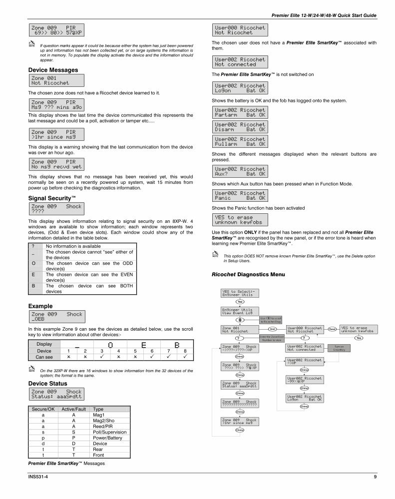
If question marks appear it could be because either the system has just been powered up and information has not been collected yet, or on large systems the information is not in memory. To populate the display activate the device and the information should appear.
Device Messages Zone 001
Not Ricochet
The chosen zone does not have a Ricochet device learned to it.
Zone 009 PIR
Msg ??? mins ago
This display shows the last time the device communicated this represents the last message and could be a poll, activation or tamper etc.....
Zone 009 PIR
>1hr since msg
This display is a warning showing that the last communication from the device was over an hour ago.
Zone 009 PIR
No msg recvd yet
This display shows that no message has been received yet, this would normally be seen on a recently powered up system, wait 15 minutes from power up before checking the diagnostics information.
Signal Security™ Zone 009 Shock
????
This display shows information relating to signal security on an 8XP-W. 4 windows are available to show information; each window represents two devices, (Odd & Even device slots). Each window could show any of the information detailed in the table below.
? No information is available _ The chosen device cannot “see” either of
the devices O The chosen device can see the ODD
device(s) E The chosen device can see the EVEN
device(s) B The chosen device can see BOTH
devices
Example Zone 009 Shock
_OEB
In this example Zone 9 can see the devices as detailed below, use the scroll key to view information about other devices:-
Display _ O E B Device 1 2 3 4 5 6 7 8
Can see
On the 32XP-W there are 16 windows to show information from the 32 devices of the system; the format is the same.
Device Status Zone 009 Shock
Status: aaaSpdtt
Secure/OK Active/Fault Type a A Mag1 a A Mag2/Sho a A Reed/PIR s S Poll/Supervision p P Power/Battery d D Device t T Rear t T Front
Premier Elite SmartKey™ Messages
User000 Ricochet
Not Ricochet
The chosen user does not have a Premier Elite SmartKey™ associated with them.
User002 Ricochet
Not connected
The Premier Elite SmartKey™ is not switched on
User002 Ricochet
Logon Bat OK
Shows the battery is OK and the fob has logged onto the system.
User002 Ricochet
Partarm Bat OK
User002 Ricochet
Disarm Bat OK
User002 Ricochet
Fullarm Bat OK
Shows the different messages displayed when the relevant buttons are pressed.
User002 Ricochet
Aux? Bat OK
Shows which Aux button has been pressed when in Function Mode.
User002 Ricochet
Panic Bat OK
Shows the Panic function has been activated
YES to erase
unknown keyfobs
Use this option ONLY if the panel has been replaced and not all Premier Elite SmartKey™ are recognised by the new panel, or if the error tone is heard when learning new Premier Elite SmartKey™.
This option DOES NOT remove known Premier Elite SmartKey™, use the Delete option in Setup Users.
Ricochet Diagnostics Menu
Engineer Utils
View Event Log
YES to Select:-
Engineer Utils
y
Zone 009 ShockStatus: aaaSpdtt
?
Zone 009 Shock
->???->???->XP
Zone 009 Shock ??>> ??>> ?? XP
C
Zone 001
Not Ricochet
C
E nter the Zone/UserNumber to view
O User000 Ricochet
Not Ricochet
Use to sc rollto R ic oc het Diag
?
User002 Ricochet
Not connected
Turn onS ma rtKey
@
Zone 009 Shock????????????????
C
Zone 009 Shock>1hr since msg
C
C
User002 Ricochet->XP
User002 Ricochet-99>> XP
C
@
User002 RicochetLogon Bat OK
C
C
YES to erase
unknown keyfobs
y
Premier Elite 12-W/24-W/48-W Quick Start Guide
10 INS531-4
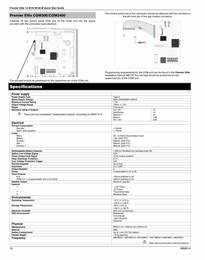
Premier Elite COM300/COM2400
Carefully lift the control panel PCB and fix the COM unit into the space provided with the connection lead attached.
TRT1R1
Audio
Com
1
The red lead should be positioned on the uppermost pin of the COM unit.
The control panel end of the connector should be attached with the red lead on the left most pin of the digi modem connector.
TRT1R1
Programming requirements for the COM unit can be found in the Premier Elite installation manual INS176.The red lead should be positioned on the uppermost pin of the COM unit.
Specifications
Power supply Power Supply Type Type A Mains Supply Voltage: 220V-240V@50Hz 220mA Maximum Current Rating 1.5A Output Voltage Range 13Vdc +/- 2% Ripple 0.5V pk-pk Maximum rating of Outputs
These are not considered "independent outputs" according to EN50131-6
Aux 12V Bell/Strobe Network 1 Battery DC+/DC-
1A 1A 1A 1.6A 0.9A
Electrical
Current Consumption Standby Alarm (with speaker)
<150mA <175mA
Fuses Mains Battery Auxiliary Bell Network 1
3A - 3.15AmA,slow/medium blow 1.6A, 250V PTC 900mA, 250V PTC 900mA, 250V PTC 900mA, 250V PTC
Rechargeable Battery Capacity 1.2Ah to 7Ah Maximum recharge time 72h Battery Low Voltage Signal 9.5V Power Output Fault Signal 10.5V (mains present) Deep Discharge Protection 8.1V Over Voltage Protection Trigger 16V Remote Keypads Up to four Expanders 2 or 3 8XP Output Modules 2 Zones 4 expandable to 24 or 48 Panel Outputs
8 @ PGM X 2 ( 1 programmable only on 24-W)@
100mA switched to 0V 500mA switched to 0V
Speaker Output Minimum load 8Ω Network
+ - T R
+12V Power 0V Power Transmitted Data Received Data
Environmental
Operating Temperature -10°C (+14°F) to +50°C (+132°F)
Storage Temperature -20°C (-4°F) to +60°C (+140°F)
Maximum Humidity 95% non-condensing EMC Environment Residential
Commercial Light Industrial Industrial
Physical
Dimensions 260mm (h) x 300mm (w) x 85mm (d) Material ABS Battery Compartment Up to t one 12V 7Ah battery Packed Weight 1.8 Kg (approx)
Frequency 868.0MHz – 868.6MHz or 433.05MHz – 434.79MHz or 866.0Mhz –866.6MHz
Please refer to product label to determine frequency

Premier Elite 12-W/24-W/48-W Quick Start Guide
INS531-4 11
Standards
2004/108/EC (CE directive): Hereby, Texecom declares that this device is in compliance with the essential requirements and other relevant provisions of Directive 2004/108/EC.
Weee Directive: 2002/96/EC (WEEE directive): Products marked with this symbol cannot be disposed of as unsorted municipal waste in the European Union. For proper recycling, return this product to your local supplier upon the purchase of equivalent new equipment, or dispose of it at designated collection points. For more information see: www.recyclethis.info.
RoHs Directive: 2002/95/EC RoHS Compliant. Hereby, Texecom declares that this device does not contain lead, mercury, cadmium, hexavalent chromium, polybrominated biphenyls (PBB) or polybrominated depheny ethers (PBDE) in more than the percentage specified by EU directive 2002/95/EC, except exemptions stated in EU directive 2002/95/EC annex. This product is a Type B Moveable device and is suitable for use in systems designed to comply with EN 50131-1, EN50131-3, EN50131-5-3 and PD6662 at Grade 2 and Environmental Class II.
EN Standard Premier Elite12-W/24-W/48-W Premier Elite SmartKey™
Premier Elite XT/QD-W
Premier Elite™ Impaq plus-W
Premier Elite™ Impaq Contact -W
EN60950-1 EN61000-6-3 EN 301 489-3 EN50130-4 A1: + A2: EN300 220-1 EN50131-1 EN50131-2-2 EN 50131-2-6 EN50131-3 EN50130-5 EN50131-5-3 EN50131-6 PD6662
Warranty All Texecom products are designed for reliable, trouble-free operation. Quality is carefully monitored by extensive computerised testing. As a result the Premier Elite 12-W/24-W/48-W is covered by a two-year warranty against defects in material or workmanship.
As the Premier Elite 12W/24-W/48-W is not a complete alarm system but only a part thereof, Texecom cannot accept responsibility or liability for any damages whatsoever based on a claim that the Premier Elite™ 12-W/ 24-W/48-W failed to function correctly. Due to our policy of continuous improvement Texecom reserve the right to change specification without prior notice.
Premier & Premier Elite are trademarks of Texecom Ltd.
SmartKey is a trademark of Texecom Ltd.
Ricochet is a trademark of Texecom Ltd.
SignalSecurity is a trademark of Texecom Ltd.
© TEXECOM LTD 2013

Texecom Limited, Bradwood Court, St. Crispin Way, Haslingden, Lancashire BB4 4PW, England.
Technical Support: UK Customers Tel: 08456 300 600
(Calls charged at local rate from a BT landline. Calls from other networks may vary.)
International Customers Tel: +44 1706 233875 Email: [email protected]
© Texecom Limited 2013 INS531-4
C er tif ic ate N umbe r : F M 35285
Recommended