PRELIMINARY SEWER STUDY
August 30, 2016
Prepared For:
Meritage Homes of California, Inc. 1671 E. Monte Vista Ave, Suite 214
Vacaville, CA 95688
Prepared By:
TSD Engineering, Inc. Chris Schulze PE #59220 31 Natoma St., Suite #160
Folsom, CA 95630

- i -
T A B L E O F C O N T E N T S
I. INTRODUCTION .. . . . . . . . . . . . . . . . . . . . . . . . . . . . . . . . . . . . . . . . . . 2
II. PROJECT DESCRIPTION ... . . . . . . . . . . . . . . . . . . . . . . . . . . . . . 2
III. ASSUMPTIONS ... . . . . . . . . . . . . . . . . . . . . . . . . . . . . . . . . . . . . . . . . . . . . 3
IV. PROPOSED DESIGN ... . . . . . . . . . . . . . . . . . . . . . . . . . . . . . . . . . . . . 4
V. CONCLUSION ... . . . . . . . . . . . . . . . . . . . . . . . . . . . . . . . . . . . . . . . . . . . . . 4
VI. REFERENCES ... . . . . . . . . . . . . . . . . . . . . . . . . . . . . . . . . . . . . . . . . . . . . . . . 5
APPENDIX A – VICINITY MAP
APPENDIX B – SOUTHEAST SEWER SERVICE AREA ANAYLSIS
APPENDIX C – DEMAND CALCULATIONS
APPENDIX D – PIPE DESIGN

I. INTRODUCTION This document examines the capability of a proposed sewer lift station located adjacent
to the Providence Park Subdivision, east of the intersection of PFE Road and Antelope
North Road to serve the southeast area of the Dry Creek West Placer Community. The
Dry Creek West Placer Community extends south of Baseline Road, West of the Roseville
City Limits, north of the Sacramento County Line and east of the Sutter County Line. As
part of preceding developments, a sewer lift station was constructed to serve the area
north of Dry Creek and west of Cook Riolo Road, this document examines ability of the
proposed lift station to serve the area south of Dry Creek and east of Cook Riolo, north of
the Sacramento County Line and West of the Roseville City Limits (hereinafter referred to
as the Scope Area) as shown on the Vicinity Map located in Appendix A.
II. PROJECT LOCATION AND DESCRIPTION The Providence Park Subdivision is proposed to develop 308 single family homes located
north of the Sacramento County Line, East and West of Antelope North Road and South
of PFE Road. As part of the development, a sewer lift station located approximately 600
feet east of the intersection of Antelope North Road and PFE Road is proposed to serve
the proposed subdivision as well as possible future development in the Scope Area. Sewer
flows from the Scope Area will gravity flow to the proposed lift station. The sewer flows
will then be conveyed through a force main north across PFE Road, then east within an
existing utility easement approximately 900 linear feet, during this reach, the force main
will cross beneath Dry Creek. Once clear of Dry Creek, the force main will return to PFE
Road and continue east to discharge to a location south of Hilltop Circle to be determined
at a later date through coordination between Placer County, the City of Roseville and
TSD Engineering, Inc. From this point the sewage will gravity flow to the Dry Creek
Wastewater Treatment Plant located north of Hilltop Circle

III. ASSUMPTIONS To define the limits of service, it is assumed that gravity lines will be designed and
constructed at the minimum slopes outlined in the Placer County Land Development
Manual (Reference 1, hereinafter referred to as the Manual). Pipe sizes required to
serve the Scope Area were assumed using the Manning’s Equation to determine the
capacity of typical pipe diameters flowing at 70 percent full and a Manning’s
Roughness Coefficient of 0.013. Estimated Peak Wet Weather Flows (PWWF)
determined assuming the flows listed in the Southeast Area Sewer Master Plan
(Reference 2, hereinafter referred to as the SASMP) and shown below.
Average Dry Weather Flows (ADWF) including a Factor of Safety of 2.0
Residential Development = 380 gallons per day per EDU
Industrial Development = 1,700 gallons per day per Acre
= 4.50 EDUs per Acre
Commercial Development = 1,700 gallons per day per Acre
= 4.50 EDUs per Acre
Peak Wet Weather Flow (PWWF)
Multiply by a peaking factor derived from a graph on Figure 1 in
Appendix C.
Equivalent Dwelling Units were determined by assuming that each parcel of land
within the Scope Area is developed to the maximum density allowed per the Dry
Creek West Placer Community Plan “Land Use Map”.

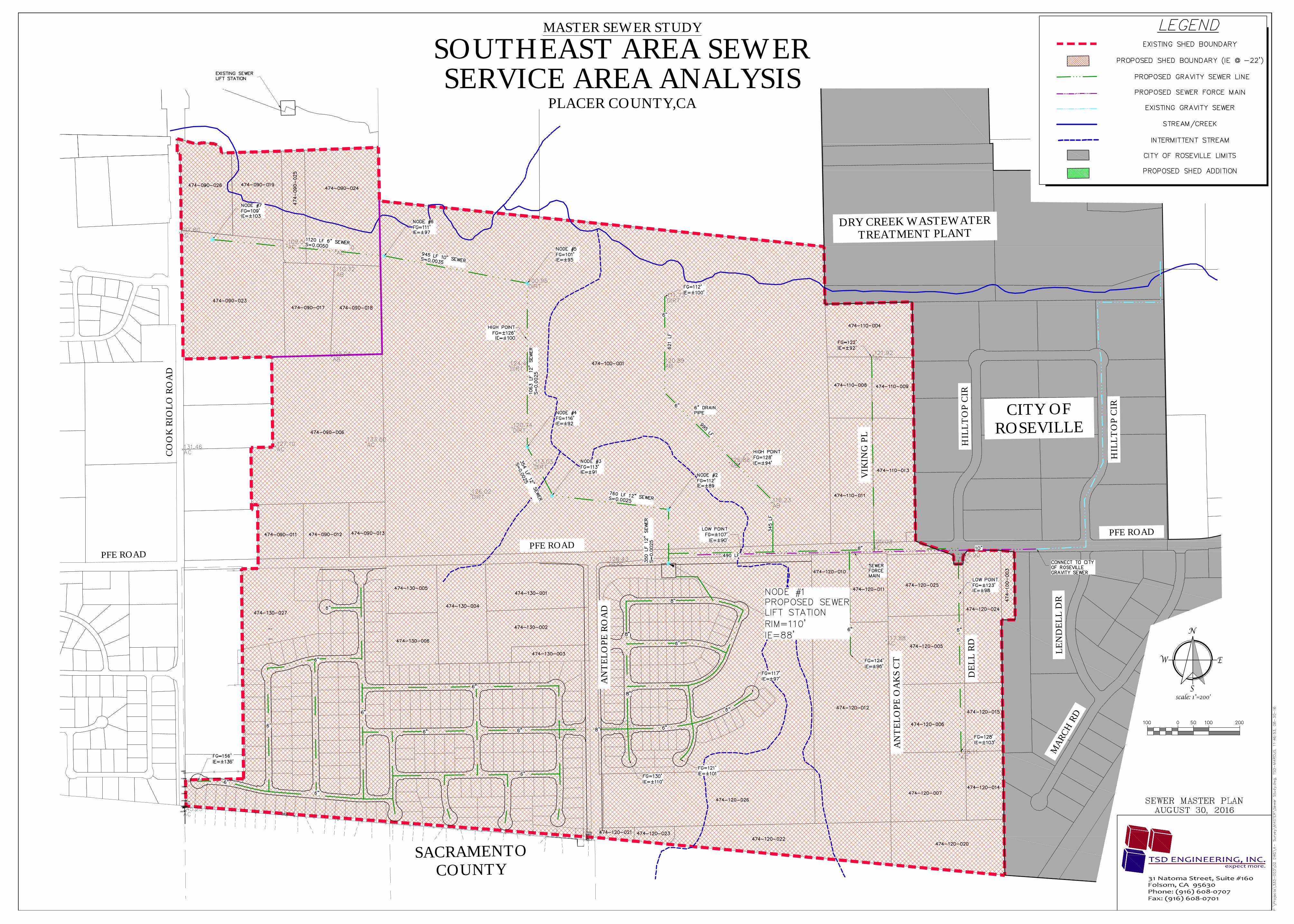
IV. PROPOSED DESIGN The proposed lift station will be located approximately 600 feet east of the intersection of
PFE Road and North Antelope Road. The rim of the wet well is planned to be set at an
elevation of approximately 110’ above sea level and extend to a maximum depth of 22
feet with the lowest inflow invert of approximately 88 feet above sea level. If constructed
with minimum pipe slopes, the sewer lift station can serve the area shown on the Sewer
Service Area Analysis Exhibit, Appendix B, through a gravity flow system.
It should be noted that the sewer alignment is schematic in nature and is only intended to
display the ability to serve the furthest reaches of the Scope Area. As the sewer system is
built in the future, the exact location of the public sewer facilities and pipe sizes required
to serve the planned developments will be determined by the design engineer for the
proposed projects.
The downstream facilities, including the wastewater treatment plant that will ultimately
receive the sewage generated in the Scope Area, are located in the jurisdiction of the City
of Roseville. It has been determined that future discussion between Placer County, the
City of Roseville and the Design Engineer (TSD Engineering, Inc.) will be held to
determine the exact location the proposed system will tie in to the City of Roseville
system, analysis of the downstream facilities will be conducted at that time.
V. CONCLUSION The proposed lift station will have the ablity to serve the entire Scope Area from the
proposed location. Ultimate buildout demand will be considered in the design of the
sewer lift station and the lift station will be designed with the capacity to handle the
developed flows of the Providence Park Subdivision as well as future development.
VI. REFERENCES
1. Placer County. Land Development Manual. October 29, 1996.
2. Placer County Department of Facility Services, Environmental Division. (2009). Southeast Area Sewer Master Plan. Roseville, CA: Warren Tellefson

A P P E N D I X A
Vicinity Map

PROJECT SITE
VICINITY MAPN.T.S.
SCOPE AREA
A P P E N D I X B
Southeast Area Sewer Service Area Analysis
TSD ENGINEERING, INC.
31 Natoma Street, Suite #160Folsom, CA 95630Phone: (916) 608-0707Fax: (916) 608-0701
expect more.
MASTER SEWER STUDY
SOUTHEAST AREA SEWERSERVICE AREA ANALYSIS
PLACER COUNTY,CA
N
S
EW
scale: 1"=200'
PFE ROAD
AN
TE
LO
PE
RO
AD
CO
OK
RIO
LO
RO
AD
SACRAMENTO
COUNTY
CITY OF
ROSEVILLE
DRY CREEK WASTEWATER
TREATMENT PLANT
PFE ROAD
PFE ROAD
HIL
LT
OP
CIR
HIL
LT
OP
CIR
VIK
ING
PL
AN
TE
LO
PE
OA
KS
CT
DE
LL
RD
LE
ND
EL
L D
RM
AR
CH
RD

A P P E N D I X C
Demand Calculations

CSA 173 SOUTHEAST SEWER AREA ANAYLSISASSUMPTIONS
Pipe Capacities
1. All capacity calcs are based on the Manning Formula with an N=0.013
Pipe Capacities at minimum grades
Pipe D, in Std. Slope Capacity, mgd*6 0.005 0.2578 0.0035 0.463 *= Equations used in this column used throughout the analysis
10 0.0025 0.71012 0.002 1.03315 0.0015 1.62218 0.0012 2.35921 0.001 3.24824 0.001 4.63827 0.001 6.34930 0.001 8.409
Definitions
ADWF = Average Dry Weather Flow = The average flow (at a given metering location) for the monthsof July-August-September for the most current year or best year available
ADWFEDU = ADWF / Total EDUs above meter stationPDWF = Peak Dry Weather Flow = The average daily peak flow during the same months used
for ADWF calculationsDWPF = Dry Weather Peaking Factor = PDWF / ADWFPWWF = Peak Wet Weather Flow = The best available instantious peak flow recorded, usually
during a major storm. An effort shoud be made to develop a 10-year peak storm event.Freak flow recordings may be thrown out.
WWPF = Wet Weather Peaking Factor = PWWF / ADWF
QRES = ADWFEDU X Residential EDUsQNON-RES = ADWFEDU X Non-Residential EDUsQCAPACITY = Hydraulic Capacity of a pipe.
DEVELOPED FACTORS
Factor Units
1700 gpd/acre
Varies from graph
380 gpd/edu
4.50 edu/acre
ZoningResidential
Comm. or IndustComm. or Indust
Title
ADWFEDU
WWPF
ADWFEDU
ADWFEDU
P:\Projects\333-003\03 REPORTS\SANITARY SEWER\2016-0811 Revised Prelim Sewer Study\2016-0318 CSA 173 Southeast Master Plan.xls PAGE 1 OF 1

CSA 173 SOUTHEAST SEWER AREA ANALYSISEDU CALCULATIONS
APNGENERAL PLAN
DESIGNATIONEDU per
Acre ACREAGE
BUILDOUT EDUs @
100%COMMENTS
474-090-019 LDR 2.00 4.2 8.4 Node 7474-090-025 LDR 2.00 2.5 5.0 Node 7474-090-024 LDR 2.00 8.3 16.6 Node 7474-090-023 LDR 2.00 11.8 23.6 Node 7474-090-017 LDR 2.00 4.3 8.6 Node 7474-090-018 LDR 2.00 4.2 6.7 Node 7474-090-006 LDR 2.00 16.9 33.8 Node 6474-090-026 LDR 2.00 3.8 7.6 Noide 7474-100-001 Industrial 2.25 78.0 175.5 Node 4474-100-001 HDR 10.00 31.0 310.0 Node 6474-100-001 LDR 2.00 47.0 94.0 Node 5
474-130-002 Professional 4.50 3.7 16.7474-130-003 Professional 4.50 1.1 5.0474-120-021 Industrial 4.50 0.5 2.3474-120-023 Industrial 4.50 0.6 2.7474-120-022 Industrial 4.50 6.7 30.2474-120-0218 Industrial 4.50 11.2 50.4474-120-017 Industrial 4.50 26.9 121.1474-120-005 Industrial 4.50 5.0 22.5474-120-006 Industrial 4.50 5.0 22.5474-120-007 Industrial 4.50 5.0 22.5474-120-010 Industrial 4.50 1.8 8.1474-120-011 Industrial 4.50 2.1 9.5474-120-012 Industrial 4.50 15.3 68.9474-120-013 Industrial 4.50 4.9 22.1474-120-014 Industrial 4.50 2.5 11.3474-120-015 Industrial 4.50 2.5 11.3474-120-016 Industrial 4.50 4.7 21.2474-120-020 Industrial 4.50 5.6 25.2474-110-004 Industrial 4.50 5.0 22.5474-110-008 Industrial 4.50 2.5 11.3474-110-009 Industrial 4.50 2.5 11.3474-110-011 Industrial 4.50 4.9 22.1474-110-013 Industrial 4.50 4.8 21.6474-130-001 Professional 4.50 4.4 19.8474-130-004 LDR 2.00 5.2 10.4474-130-005 LDR 2.00 2.2 4.4474-130-006 LDR 2.00 2.5 5.0474-130-011 LDR 2.00 2.0 4.0474-130-013 LDR 2.00 30.0 60.0
474-130-014 School 9.4 15.0Eureka School - also inculded
trunk to west474-130-015 LDR 2.00 1.0 2.0474-009-011 LDR 2.00 2.4 4.8474-009-012 LDR 2.00 2.4 4.8474-009-013 LDR 2.00 1.9 3.8474-130-007 Residential N/A 8.5474-130-017 Residential N/A 1.5474-130-018 Residential N/A 6.4474-130-007 Residential N/A 6.5474-130-009 Residential N/A 5.0474-130-010 Residential N/A 4.0474-120-017 Residential N/A 18.0
Providence Park Subdivision308
North of Lift Station
South of Lift Station
P:\Projects\333-003\03 REPORTS\SANITARY SEWER\2016-0811 Revised Prelim Sewer Study\2016-0318 CSA 173 Southeast Master Plan.xls PAGE 1 OF 1

A P P E N D I X D
Pipe Design
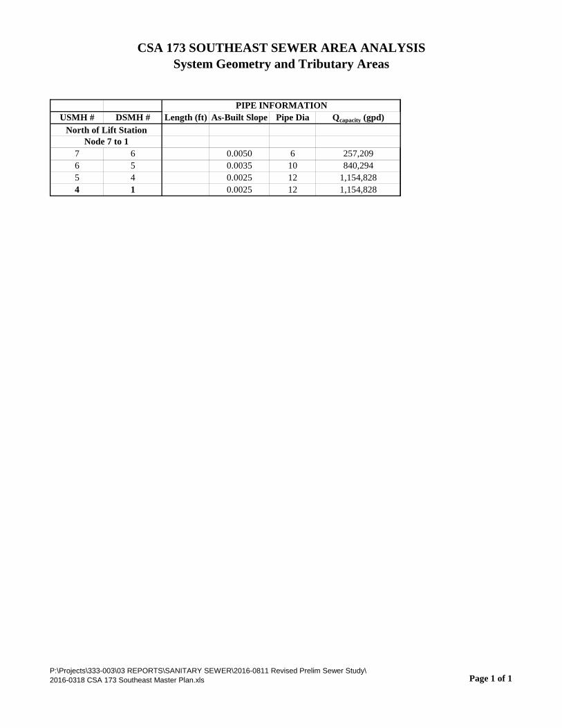
CSA 173 SOUTHEAST SEWER AREA ANALYSISSystem Geometry and Tributary Areas
USMH # DSMH # Length (ft) As-Built Slope Pipe Dia Qcapacity (gpd)
7 6 0.0050 6 257,2096 5 0.0035 10 840,2945 4 0.0025 12 1,154,8284 1 0.0025 12 1,154,828
PIPE INFORMATION
North of Lift StationNode 7 to 1
P:\Projects\333-003\03 REPORTS\SANITARY SEWER\2016-0811 Revised Prelim Sewer Study\2016-0318 CSA 173 Southeast Master Plan.xls Page 1 of 1


FIGURE 2CSA 173 Southeast Sewer Area Hydraulic Capacity Analysis – Buildout Conditions Model Results
MANHOLE NUMBERS
USMH # DSMH #As-Built
SlopePipe Dia QCapacity (gpd)
Res Units, EDU
Node QRES
Upstream Node
ADWF
Total ADWF at
Node
Wet Weather
PF
Node PWWF
Qcapacity
WET WEATHER CAPACITY USED (PWWF / Qcapacity)
PIPE SIZE, INCHES
Pipe Slope
7 6 0.0050 6 257,209 76.52 29,078 0 29,078 3.5 101,772 257,209 39.6% 6 0.00506 5 0.0035 10 840,294 343.80 130,644 29,078 159,722 3.0 479,165 840,294 57.0% 10 0.00355 4 0.0025 12 1,154,828 94.00 35,720 159,722 195,442 2.9 566,781 1,154,828 49.1% 12 0.00254 1 0.0025 12 1,154,828 175.50 66,690 195,442 262,132 2.8 720,862 1,154,828 62.4% 12 0.0025
TRIBUTARY FLOW CALCS, gpd CAPACITY USED, %
North of Lift Station
Node 7 to 1
P:\Projects\333-003\03 REPORTS\SANITARY SEWER\2016-0811 Revised Prelim Sewer Study\2016-0318 CSA 173 Southeast Master Plan.xls Page 1 of 1
Recommended