Prediction of Fluid Dynamics in The Inertial Confinement Fusion Chamber
by Godunov Solver With Adaptive Grid Refinement
Zoran Dragojlovic, Farrokh Najmabadi, Marcus Day
Accomplishments• IFE Chamber dynamics code SPARTAN is developed: Simulation of Physics by Algorithms based on Robust
Turbulent Approximation of Navier-Stokes Equations.• SPARTAN current features:
– 2-D Navier Stokes equations, viscosity and thermal conductivity included
– arbitrary geometry– adaptive mesh refinement
• SPARTAN tests:– Acoustic wave propagation.– Viscous channel flow.– Mach reflection.– Analysis of discretization errors to find code accuracy.
• Initial conditions from BUCKY code are used for simulations.• Two Journal articles on SPARTAN are in preparation.
• IFE Chamber dynamics code SPARTAN is developed: Simulation of Physics by Algorithms based on Robust
Turbulent Approximation of Navier-Stokes Equations.• SPARTAN current features:
– 2-D Navier Stokes equations, viscosity and thermal conductivity included
– arbitrary geometry– adaptive mesh refinement
• SPARTAN tests:– Acoustic wave propagation.– Viscous channel flow.– Mach reflection.– Analysis of discretization errors to find code accuracy.
• Initial conditions from BUCKY code are used for simulations.• Two Journal articles on SPARTAN are in preparation.

Governing Equations of Fluid Flow
2-D Navier-Stokes equations in conservative form:
Solution vector:

Governing Equations of Fluid Flow
Flux terms in x and y direction:
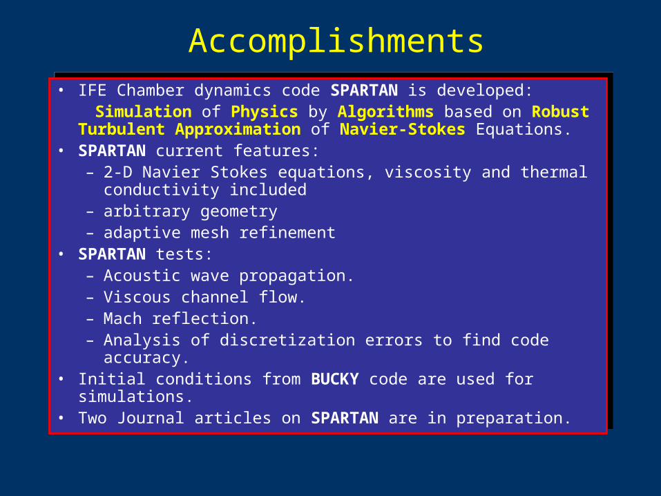
Viscosity
In general, depends on (T, Z)
T – temperature, Z – average ionization stage
2 extreme cases: neutral gas and fully ionized gas on a temperature range (10,000-60,000)K
neutral gas:
2.21 1016– T
2.5Ai
0.5
Z4 ln
---------------------kgms-------=
fully ionized gas: := (4.9 x 10⁻¹¹ – 4.4 x 10⁻⁹) Pas
:= (2.6 x 10⁻⁴ – 6.55 x 10⁻⁴) Pas
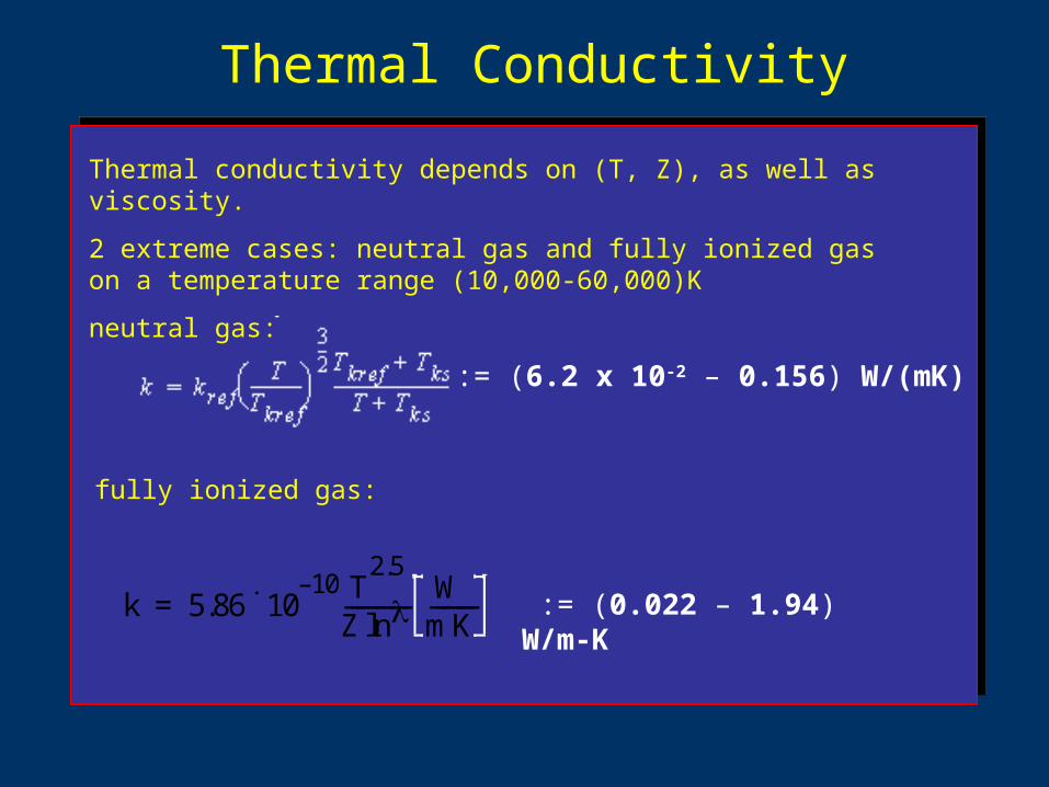
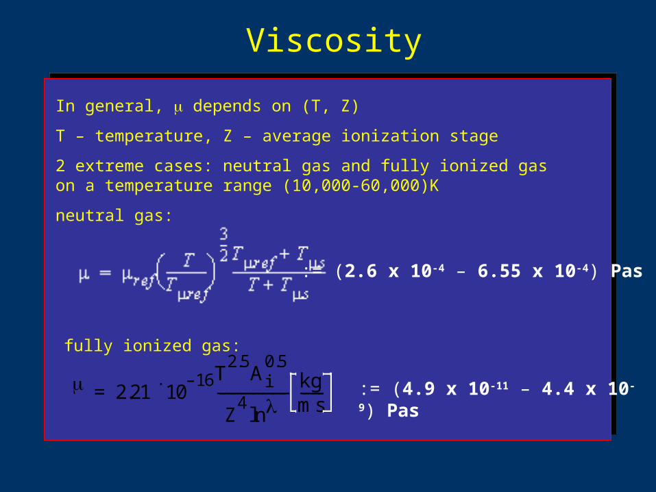
Thermal Conductivity
Thermal conductivity depends on (T, Z), as well as viscosity.
2 extreme cases: neutral gas and fully ionized gas on a temperature range (10,000-60,000)K
neutral gas:
fully ionized gas:
:= (6.2 x 10⁻² – 0.156) W/(mK)
k 5.86 1010– T
2.5
Z ln------------
WmK---------= := (0.022 – 1.94) W/m-K

Godunov Method
Introduced in 1959, as a finite volume method with a special method of upwinding.
Uses solution to a 1-D Riemann problem in order to estimate fluxes at the interface between cells.
Formulation of Riemann problem:
1-D governing equation
initial condition
U(x,0) does not necessarily satisfy the conservation laws, breaks into
fans, shocks and contact discontinuities.
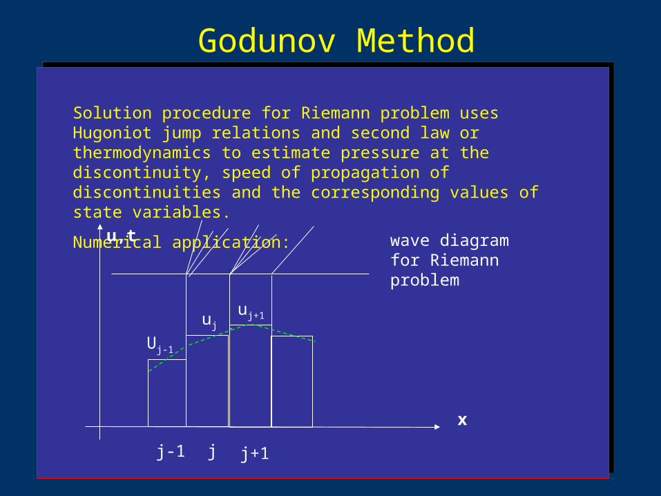
Godunov Method
Solution procedure for Riemann problem uses Hugoniot jump relations and second law or thermodynamics to estimate pressure at the discontinuity, speed of propagation of discontinuities and the corresponding values of state variables.
Numerical application:
x
u,t
j j+1j-1
wave diagram for Riemann problem
uj+1uj
Uj-1

Adaptive Mesh Refinement• Motivation: efficient grid distribution results in reasonable CPU
time.• Grid organized into levels from coarse to fine.• Solution tagging based on density and energy gradients.• Grid is refined at every time step.• Solution interpolated in space and time between the grid levels.• Referenced in: Almgren et al., 1993.
• Motivation: efficient grid distribution results in reasonable CPU time.
• Grid organized into levels from coarse to fine.• Solution tagging based on density and energy gradients.• Grid is refined at every time step.• Solution interpolated in space and time between the grid levels.• Referenced in: Almgren et al., 1993.
chamber beam channel
wall
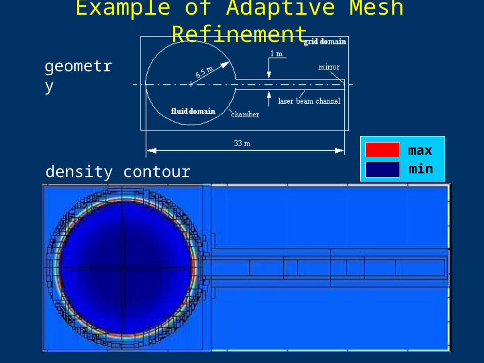
Example of Adaptive Mesh Refinement
maxmin
geometry
density contour plot

“forbidden” domain
fluid domain
embedded boundary
Embedded Boundary Algorithm
Arbitrary geometry imposed onto regular grid.
This results in formation of cells irregular in shapes and sizes.
Conservative update of irregular cells needs to be consistent and stable.
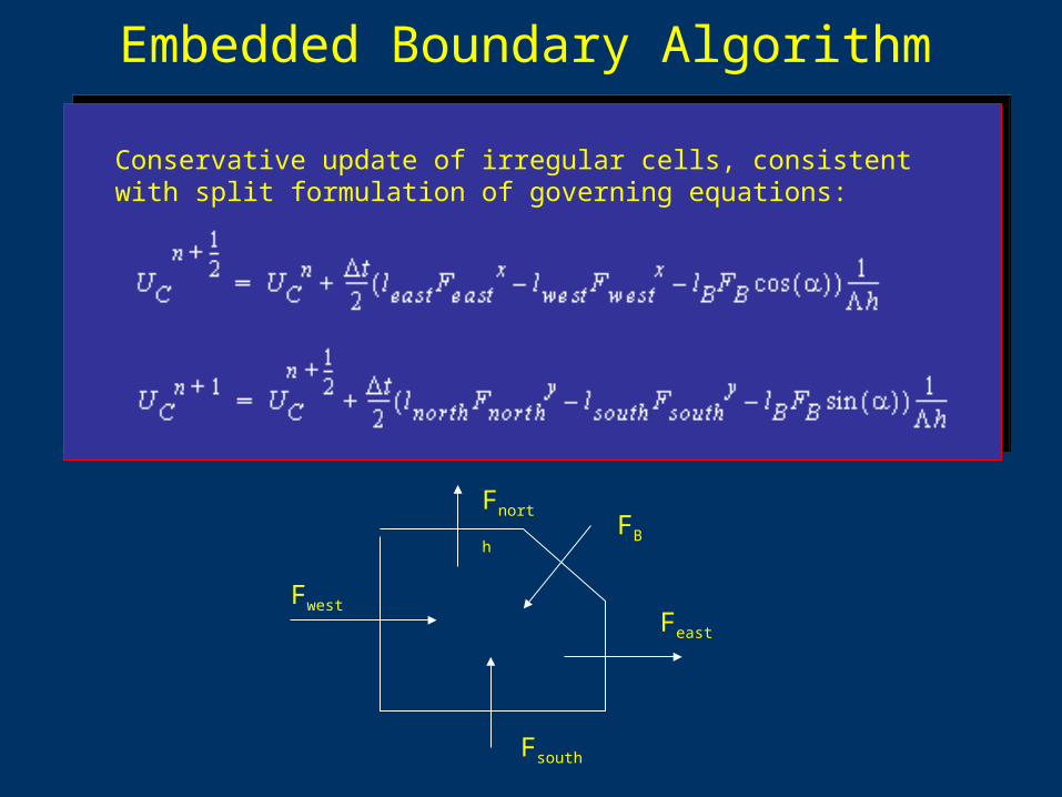
Embedded Boundary Algorithm
Conservative update of irregular cells, consistent with split formulation of governing equations:
FwestFeast
Fsouth
FnorthFB

Embedded Boundary Algorithm
irregular cell
cell for nonconservative update
fluid domain irregular cell’s
neighborhood
non-conservative update
preliminary update
Error Analysis
0.00E+00
2.00E-03
0.0000 8.0000
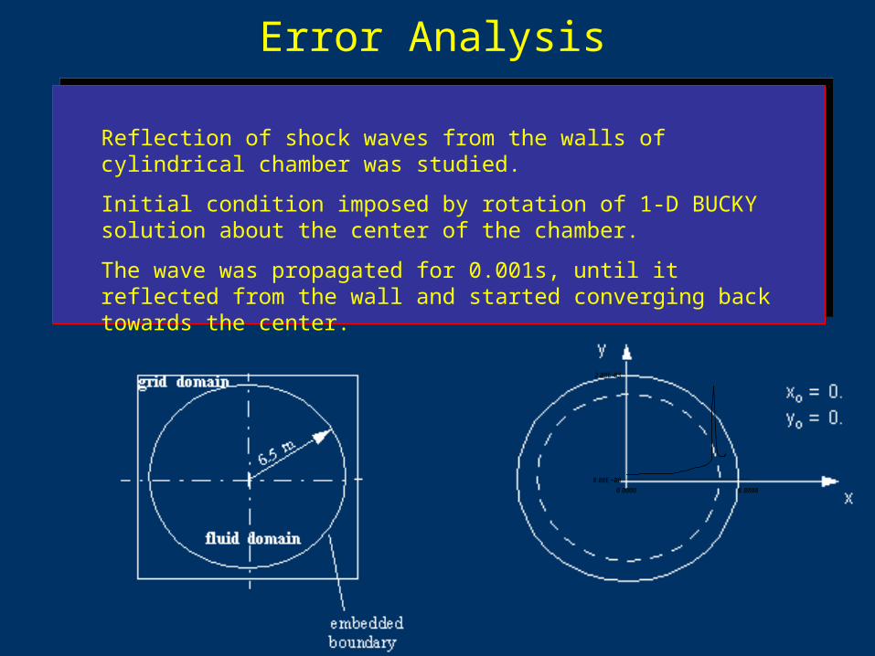
Reflection of shock waves from the walls of cylindrical chamber was studied.
Initial condition imposed by rotation of 1-D BUCKY solution about the center of the chamber.
The wave was propagated for 0.001s, until it reflected from the wall and started converging back towards the center.
Error Analysis
Two cases considered:non-diffusive flow (m, k=0.0) and diffusive flow (m, k given by Sutherland law).
Error analysis was done to determine the influence of the viscous and thermal diffusion on the accuracy of the solution.
The errors were estimated by 4th order Richardson extrapolation.

Error Analysis
density
no diffusion
min=3.68e-5 kg/m3
max=1.19e-3 kg/m3
density
diffusive flow
min=3.69e-5 kg/m3
max=2.09e-3 kg/m3
error
no diffusion
avg. = 3%
520x520 grid
error
diffusive flow
avg. = 3.1%
520x520 grid

Error Analysis
X-momentum
no diffusion
min= -1.67kg/(m2s)
max= 1.63kg/(m2s)
X-momentum
diffusive flow
min=-1.07kg/(m2s)
max=0.96kg/(m2s)
error
no diffusion
avg. = 3.6%
520x520 grid
error
diffusive flow
avg. = 3.2%
520x520 grid

Error Analysis
pressure
no diffusion
min=50.01 Pa
max=1.262e3 Pa
pressure
diffusive flow
min=50.42 Pa
max=1.24e3 Pa
error
no diffusion
avg. = 1.57%
520x520 grid
error
diffusive flow
avg. = 1.52%
520x520 grid
Error Analysis
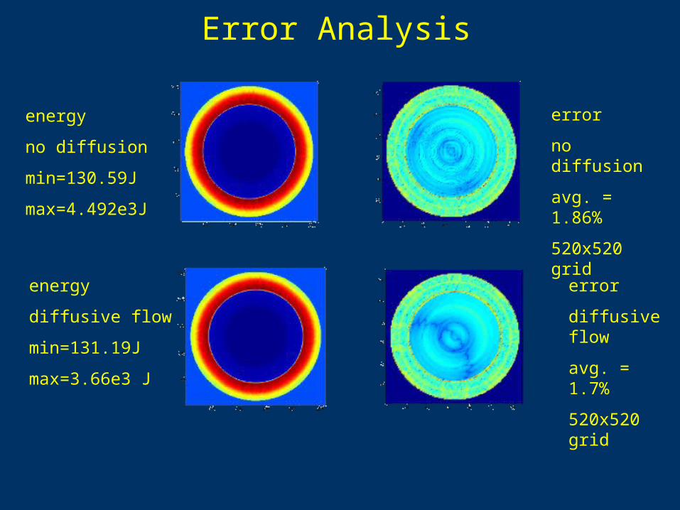
energy
no diffusion
min=130.59J
max=4.492e3J
energy
diffusive flow
min=131.19J
max=3.66e3 J
error
no diffusion
avg. = 1.86%
520x520 grid
error
diffusive flow
avg. = 1.7%
520x520 grid

Validation Problemscylindrical shock reflection from rectangular geometry
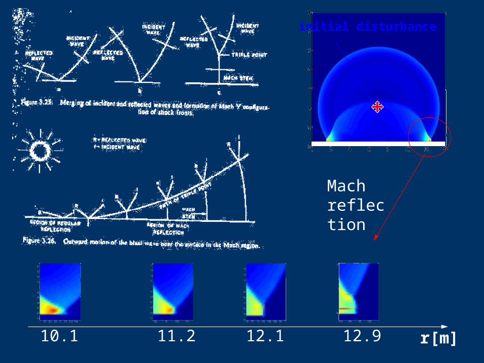
10.1 11.2 12.1 12.9 r[m]
initial disturbance
Mach reflection

Viscous Flow Through the Channel

IFE Chamber Dynamics Simulations
Objectives• Determine the influence of the following factors on the chamber
state at 100 ms:- viscosity- blast position in the chamber- heat conduction from gas to the wall.
• Chamber density, pressure, temperature, and velocity distribution prior to insertion of next target are calculated.
Objectives• Determine the influence of the following factors on the chamber
state at 100 ms:- viscosity- blast position in the chamber- heat conduction from gas to the wall.
• Chamber density, pressure, temperature, and velocity distribution prior to insertion of next target are calculated.

Numerical Simulations
IFE Chamber Simulation• 2-D cylindrical chamber with a laser beam channel on the side.• 160 MJ NRL target• Boundary conditions:
– Zero particle flux, Reflective velocity– Zero energy flux or determined by heat conduction.
• Physical time: 500 s (BUCKY initial conditions) to 100 ms.
IFE Chamber Simulation• 2-D cylindrical chamber with a laser beam channel on the side.• 160 MJ NRL target• Boundary conditions:
– Zero particle flux, Reflective velocity– Zero energy flux or determined by heat conduction.
• Physical time: 500 s (BUCKY initial conditions) to 100 ms.
Numerical Simulations
Initial Conditions• 1-D BUCKY solution for density, velocity and temperature at
500 s imposed by rotation and interpolation.• Target blast has arbitrary location near the center of the
chamber.• Solution was advanced by SPARTAN code until 100 ms were
reached.
Initial Conditions• 1-D BUCKY solution for density, velocity and temperature at
500 s imposed by rotation and interpolation.• Target blast has arbitrary location near the center of the
chamber.• Solution was advanced by SPARTAN code until 100 ms were
reached.
0.00E+00
2.00E-03
0.0000 8.0000
Effect of Viscosity on Chamber State at 100 ms
inviscid flow at 100 ms
pressure, pmean = 569.69 Pa
temperature, Tmean = 5.08 104 K
(CvT)mean = 1.412 103 J/m3
pressure, pmean = 564.87 Pa
temperature, Tmean = 4.7 104 K
(CvT)mean = 1.424 103 J/m3
viscous flow at 100 ms
Viscosity makes a difference due to it’s strong dependence on temperature.
Viscosity makes a difference due to it’s strong dependence on temperature.
maxmin

Effect of Blast Position on Chamber State at 100ms
pressure, pmean = 564.87 Pa
temperature, Tmean = 4.7 104 K
centered blast at 100 mspressure, pmean = 564.43 Pa
temperature, Tmean = 4.74 104 K
eccentric blast at 100 ms
Large disturbance due to eccentricity of blast and small numerical disturbances have the same effect after 100 ms.
Large disturbance due to eccentricity of blast and small numerical disturbances have the same effect after 100 ms.
maxmin
Effect of Blast Position on Chamber State at 100 ms
0
1000
2000
3000
4000
5000
6000
0 0.02 0.04 0.06 0.08 0.1
time [s]
pre
ss
ure
[P
a]
centered blasteccentric blast
pressure at the wall pressure at the mirror
•Mirror is normal to the beam tube.
•Pressure is conservative by an order of magnitude.
•Pressure on the mirror is so small that the mechanical response is negligible.
•Mirror is normal to the beam tube.
•Pressure is conservative by an order of magnitude.
•Pressure on the mirror is so small that the mechanical response is negligible.
200
400
600
800
1000
1200
0 0.02 0.04 0.06 0.08 0.1
time [s]
pre
ss
ure
[P
a]
centered blasteccentric blast

Effect of Wall Heat Conduction on Chamber State at 100 ms
pressure, pmean = 564.431 Pa
temperature, tmean = 4.736 104 K
insulated wall
pressure, pmean = 402.073 Pa
temperature, tmean = 2.537 104 K
wall conduction
Ionized gas or plasma makes a difference by the means of heat conduction.
Ionized gas or plasma makes a difference by the means of heat conduction.
maxmin
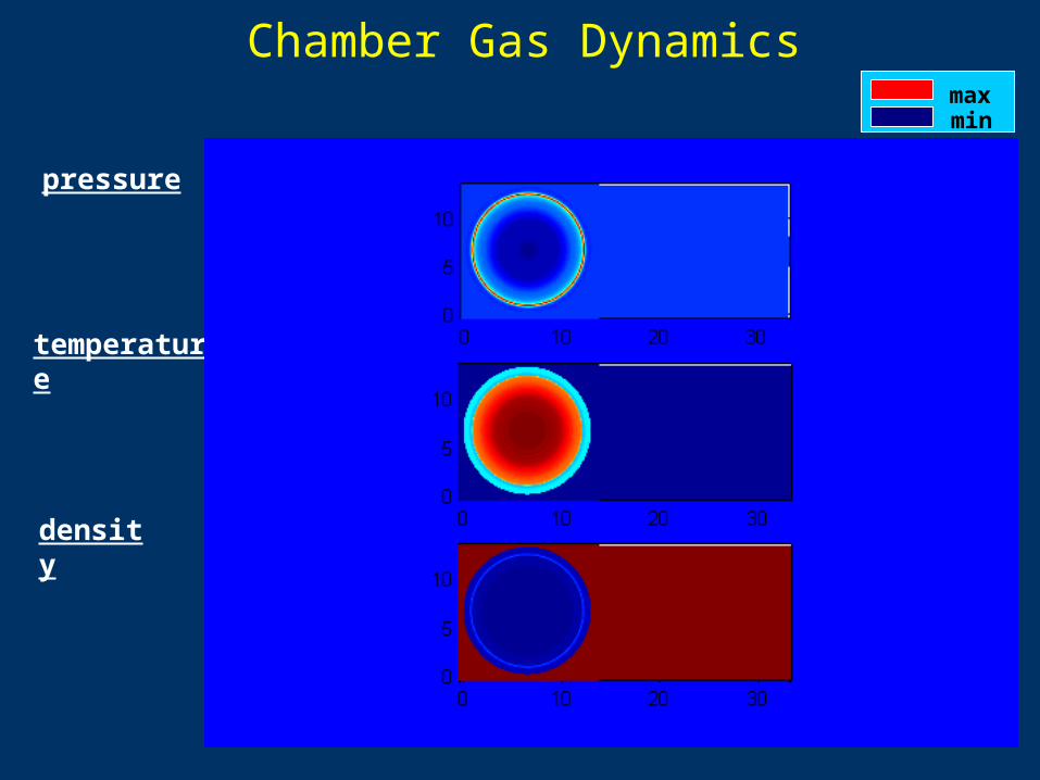
pressure
temperature
density
Chamber Gas Dynamicsmaxmin

Prediction of chamber condition at long time scale is the goal of chamber simulation research.
Chamber dynamics simulation program is on schedule. Program is based on: Staged development of Spartan simulation code. Periodic release of the code and extensive simulations while development
of next-stage code is in progress.
Chamber dynamics simulation program is on schedule. Program is based on: Staged development of Spartan simulation code. Periodic release of the code and extensive simulations while development
of next-stage code is in progress.
Documentation and Release of Spartan (v1.0) Two papers are under preparation
Exercise Spartan (v1.x) Code Use hybrid models for viscosity and thermal conduction. Parametric survey of chamber conditions for different initial conditions
(gas constituent, pressure, temperature, etc.) Need a series of Bucky runs as initial conditions for these cases. We should run Bucky using Spartan results to model the following
shot and see real “equilibrium” condition. Investigate scaling effects to define simulation experiments.

Several upgrades are planned for Spartan (v2.0)
Numeric:
Implementation of multi-species capability: Neutral gases, ions, and electrons to account for different thermal
conductivity, viscosity, and radiative losses.
Physics:
Evaluation of long-term transport of various species in the chamber (e.g., material deposition on the wall, beam tubes, mirrors) Atomics and particulate release from the wall; Particulates and aerosol formation and transport in the chamber.
Improved modeling of temperature/pressure evolution in the chamber: Radiation heat transport; Equation of state; Turbulence models.
Recommended