FLAT BAR DETAIL LINE
PRE-ENGINEERED METAL BUILDING FABRICATION
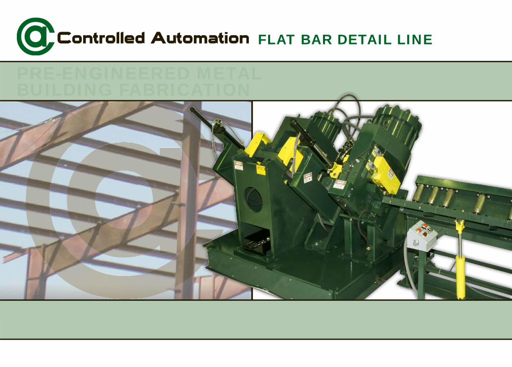
Detail Line
Controlled Automation’s Detail Production Line is one of our most in demand metal building system machines. This machine is for anyone serious about producing connection plates and base plates up to 1” thick by 12” wide. Controlled Automation continues to serve the metal building industry as the strongest supplier of beam punch lines, anglelines, plate cutting machines as well as our other fabricating machinery, and material handling systems, providing complete plant automation. Any manufacturer equipped with this Detail Line, a Flange Line and web cutting MultiMAX plasma cutting table will be able to compete with any metal building company.
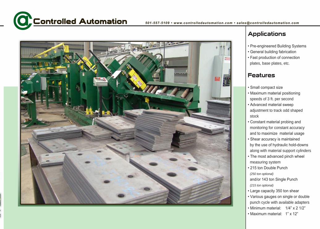
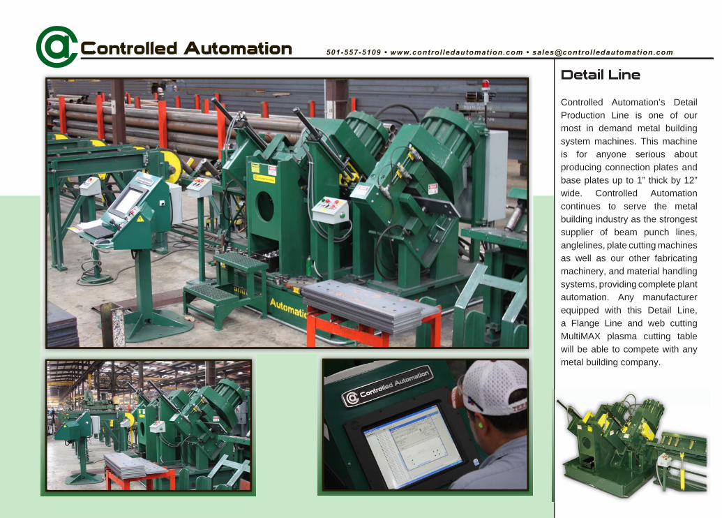
Applications
plates, base plates, etc.
Features
speeds of 3 ft. per second
adjustment to track odd shaped stock
monitoring for constant accuracy
along with material support cylinders
measuring system
(250 ton optional)
(215 ton optional)
punch cycle with available adapters
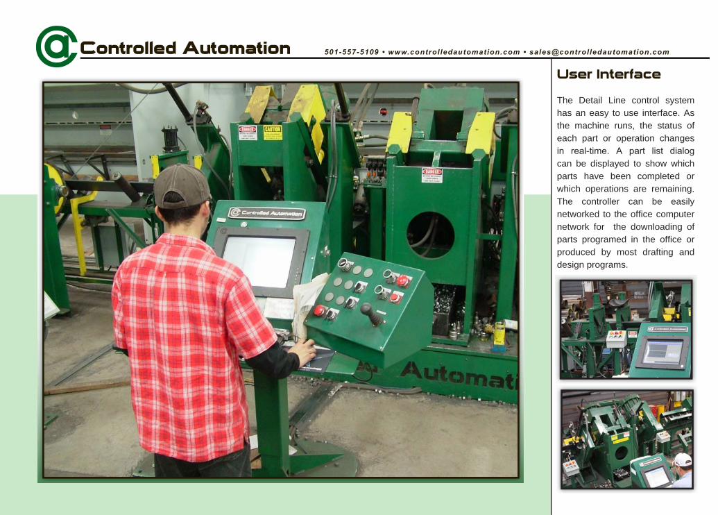
User Interface
The Detail Line control system has an easy to use interface. As the machine runs, the status of each part or operation changes
can be displayed to show which parts have been completed or which operations are remaining. The controller can be easily networked to the office computer network for the downloading of parts programed in the office or produced by most drafting and design programs.
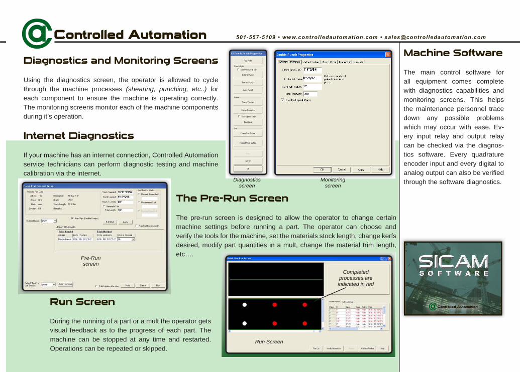
The Pre-Run Screen
machine settings before running a part. The operator can choose and verify the tools for the machine, set the materials stock length, change kerfs desired, modify part quantities in a mult, change the material trim length, etc….
Machine Software
The main control software for all equipment comes complete with diagnostics capabilities and monitoring screens. This helps the maintenance personnel trace down any possible problems which may occur with ease. Every input relay and output relay can be checked via the diagnostics software. Every quadrature encoder input and every digital to analog output can also be verified through the software diagnostics.
Diagnostics and Monitoring Screens
Using the diagnostics screen, the operator is allowed to cycle through the machine processes (shearing, punching, etc..) foreach component to ensure the machine is operating correctly. The monitoring screens monitor each of the machine components during it’s operation.
Internet Diagnostics
If your machine has an internet connection, Controlled Automation service technicians can perform diagnostic testing and machine calibration via the internet.
Run Screen
During the running of a part or a mult the operator gets visual feedback as to the progress of each part. The machine can be stopped at any time and restarted. Operations can be repeated or skipped.
Diagnosticsscreen
Monitoringscreen
Pre-Runscreen
Run Screen
Completedprocesses are indicated in red
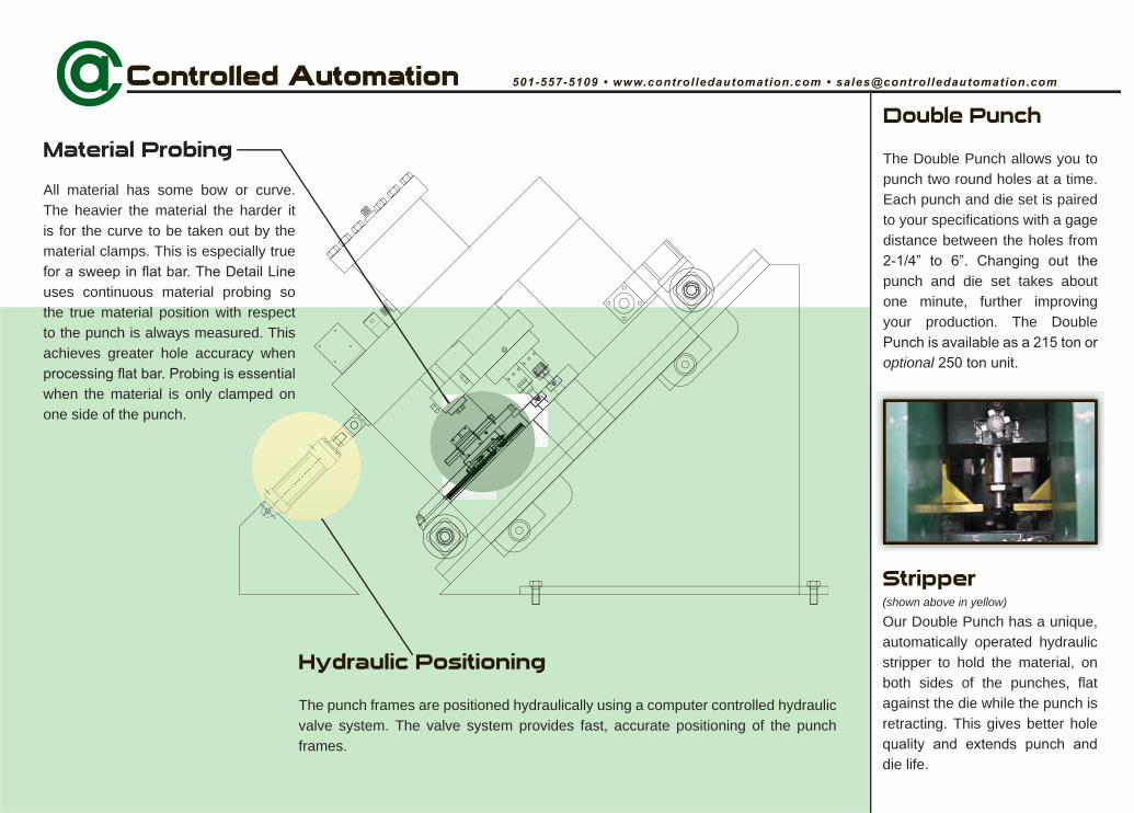
Double Punch
The Double Punch allows you to punch two round holes at a time. Each punch and die set is paired to your specifications with a gage distance between the holes from
punch and die set takes about one minute, further improving your production. The Double
optional
Material Probing
All material has some bow or curve. The heavier the material the harder it is for the curve to be taken out by the material clamps. This is especially true
uses continuous material probing so the true material position with respect to the punch is always measured. This achieves greater hole accuracy when
when the material is only clamped on one side of the punch.
Hydraulic Positioning
The punch frames are positioned hydraulically using a computer controlled hydraulic valve system. The valve system provides fast, accurate positioning of the punch frames.
Stripper(shown above in yellow)
Our Double Punch has a unique, automatically operated hydraulic stripper to hold the material, on both sides of the punches, flat against the die while the punch is retracting. This gives better hole
die life.
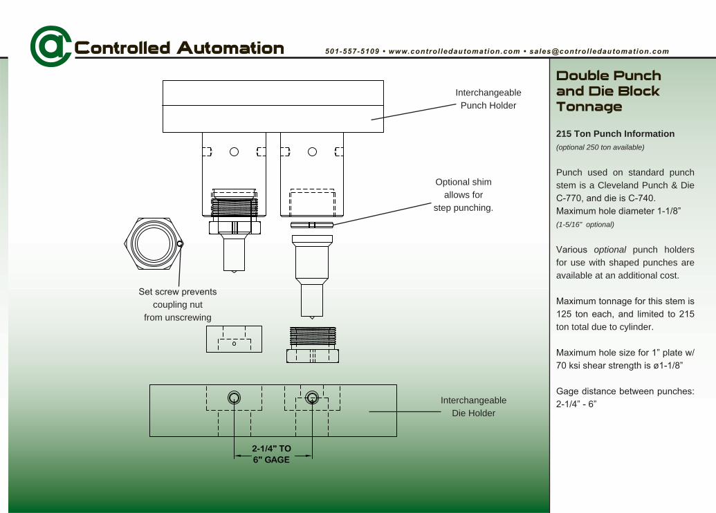
Double Punch and Die Block Tonnage
215 Ton Punch Information(optional 250 ton available)
Punch used on standard punch stem is a Cleveland Punch & Die
(1-5/16” optional)
optional punch holders for use with shaped punches are available at an additional cost.
ton total due to cylinder.
2-1/4" TO6" GAGE
Optional shimallows for
step punching.
coupling nutfrom unscrewing
InterchangeablePunch Holder
InterchangeableDie Holder
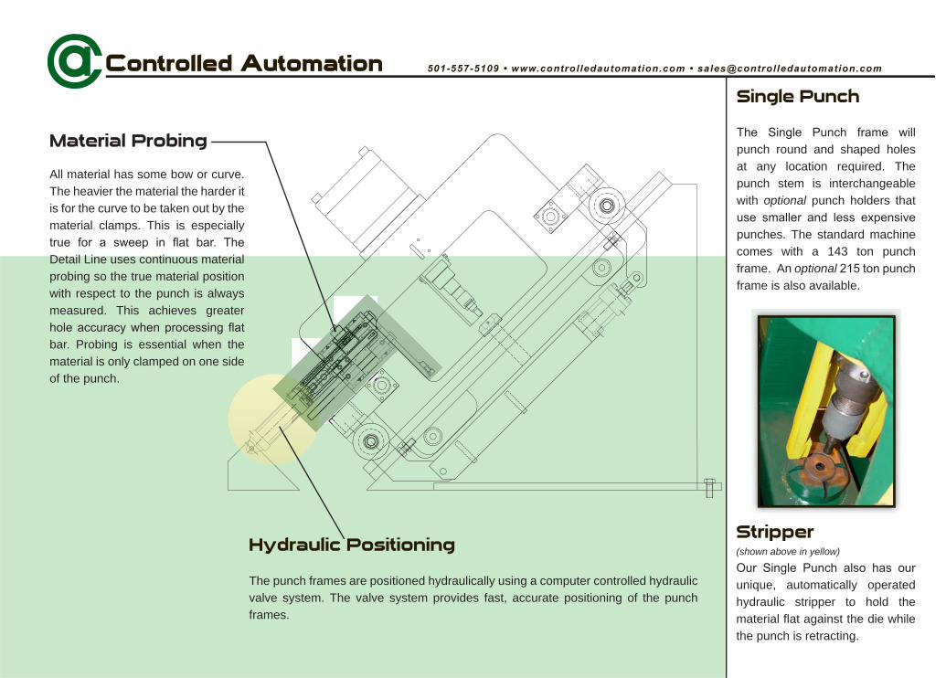
Single Punch
punch round and shaped holes at any location required. The punch stem is interchangeable with optional punch holders that
punches. The standard machine comes with a 143 ton punch frame. An optionalframe is also available.
Material Probing
All material has some bow or curve. The heavier the material the harder it is for the curve to be taken out by the material clamps. This is especially
Detail Line uses continuous material probing so the true material position with respect to the punch is always measured. This achieves greater
bar. Probing is essential when the material is only clamped on one side of the punch.
Hydraulic Positioning
The punch frames are positioned hydraulically using a computer controlled hydraulic valve system. The valve system provides fast, accurate positioning of the punch frames.
Stripper(shown above in yellow)
unique, automatically operated hydraulic stripper to hold the material flat against the die while the punch is retracting.
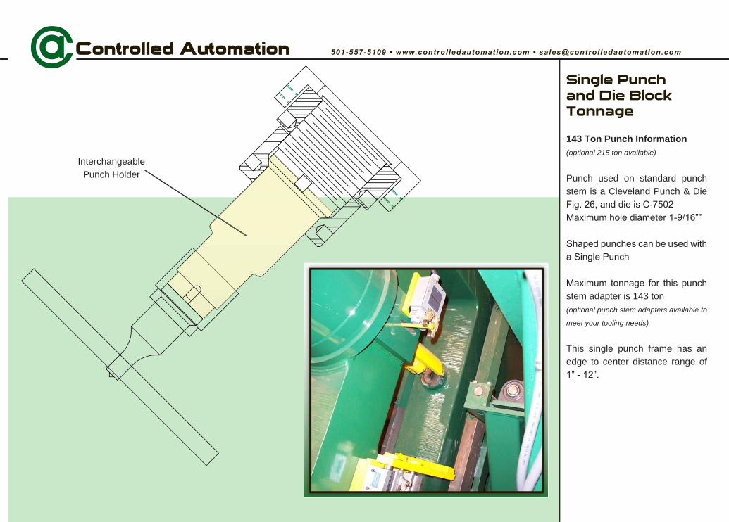
InterchangeablePunch Holder
Single Punch and Die Block Tonnage
143 Ton Punch Information(optional 215 ton available)
Punch used on standard punch stem is a Cleveland Punch & Die
stem adapter is 143 ton(optional punch stem adapters available to
meet your tooling needs)
This single punch frame has an edge to center distance range of
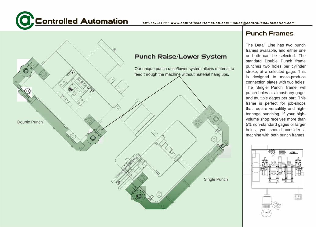
Punch Frames
The Detail Line has two punch frames available, and either one or both can be selected. The standard Double Punch frame punches two holes per cylinder stroke, at a selected gage. This
connection plates with two holes.
punch holes at almost any gage, and multiple gages per part. This
volume shop receives more than
holes, you should consider a machine with both punch frames.
Double Punch
Punch Raise/Lower System
Our unique punch raise/lower system allows material to feed through the machine without material hang ups.
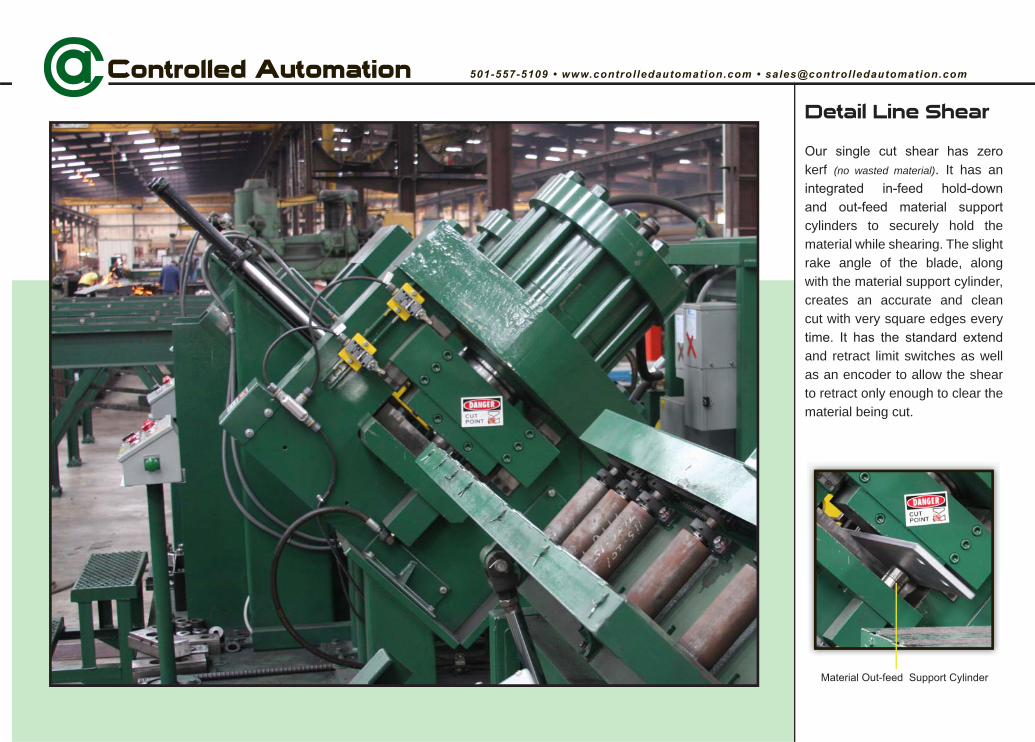
Detail Line Shear
kerf (no wasted material). It has an
cylinders to securely hold the material while shearing. The slight rake angle of the blade, along with the material support cylinder, creates an accurate and clean cut with very square edges every
and retract limit switches as well as an encoder to allow the shear to retract only enough to clear the material being cut.
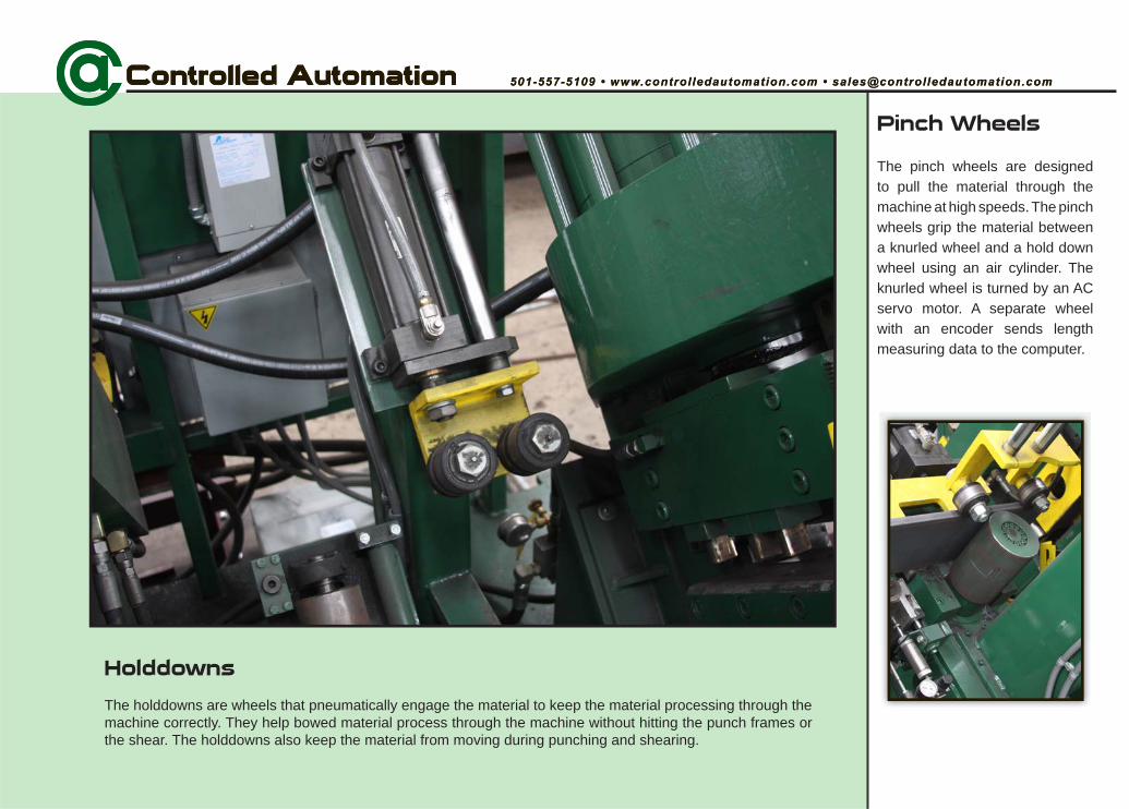
Pinch Wheels
The pinch wheels are designed to pull the material through the machine at high speeds. The pinch wheels grip the material between a knurled wheel and a hold down wheel using an air cylinder. The knurled wheel is turned by an AC servo motor. A separate wheel with an encoder sends length measuring data to the computer.
Holddowns
The holddowns are wheels that pneumatically engage the material to keep the material processing through the machine correctly. They help bowed material process through the machine without hitting the punch frames or the shear. The holddowns also keep the material from moving during punching and shearing.
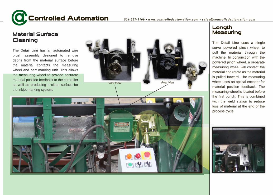
LengthMeasuring
The Detail Line uses a single servo powered pinch wheel to pull the material through the machine. In conjunction with the powered pinch wheel, a separate measuring wheel will contact the material and rotate as the material is pulled forward. The measuring wheel uses an optical encoder for material position feedback. The measuring wheel is located before
with the weld station to reduce loss of material at the end of the process cycle.
Material Surface Cleaning
The Detail Line has an automated wire brush assembly designed to remove debris from the material surface before the material contacts the measuring wheel and part marking unit. This allows the measuring wheel to provide accurate material position feedback to the controller as well as producing a clean surface for the inkjet marking system.
Front View Rear View
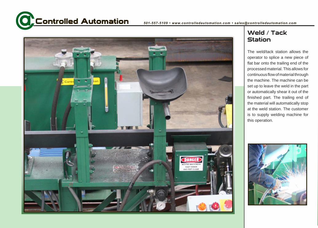
Weld / Tack Station
The weld/tack station allows the operator to splice a new piece of flat bar onto the trailing end of the processed material. This allows for continuous flow of material through the machine. The machine can be set up to leave the weld in the part or automatically shear it out of the finished part. The trailing end of the material will automatically stop at the weld station. The customer is to supply welding machine for this operation.
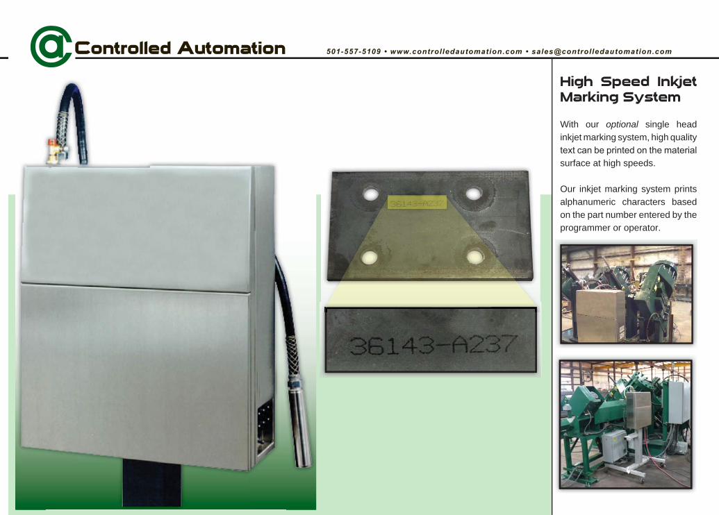
High Speed Inkjet Marking System
With our optional single head inkjet marking system, high quality
surface at high speeds.
Our inkjet marking system prints alphanumeric characters based on the part number entered by the programmer or operator.
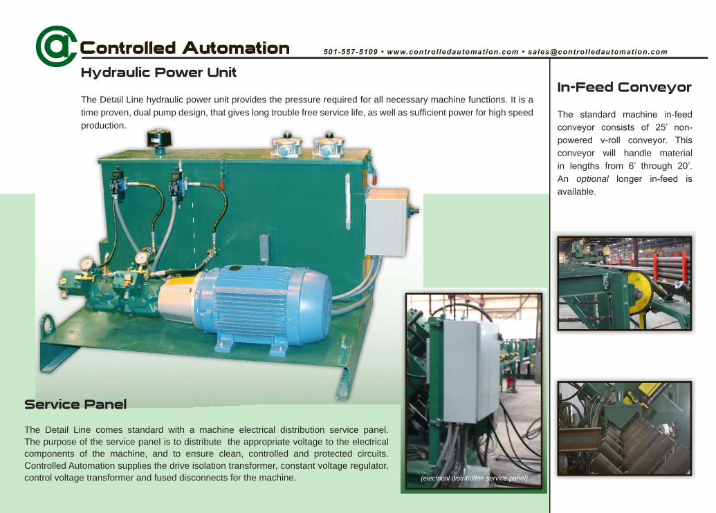
In-Feed Conveyor
conveyor will handle material
An optionalavailable.
Hydraulic Power Unit
The Detail Line hydraulic power unit provides the pressure required for all necessary machine functions. It is a time proven, dual pump design, that gives long trouble free service life, as well as sufficient power for high speed production.
Service Panel
The Detail Line comes standard with a machine electrical distribution service panel. The purpose of the service panel is to distribute the appropriate voltage to the electrical components of the machine, and to ensure clean, controlled and protected circuits.Controlled Automation supplies the drive isolation transformer, constant voltage regulator, control voltage transformer and fused disconnects for the machine. (electrical distribution service panel)
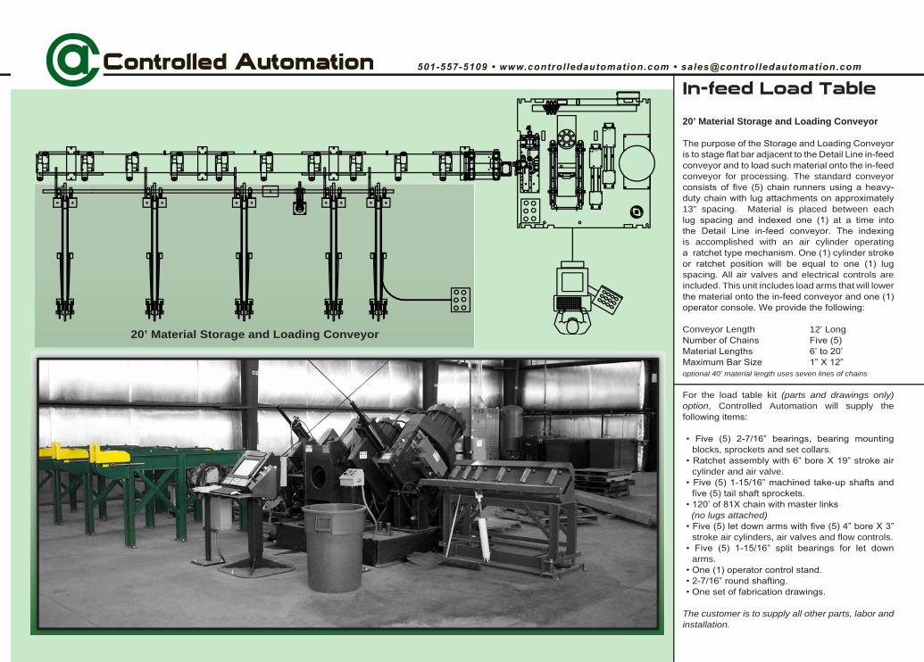
In-feed Load Table
20’ Material Storage and Loading Conveyor
conveyor for processing. The standard conveyor
13” spacing. Material is placed between each
is accomplished with an air cylinder operating
spacing. All air valves and electrical controls are included. This unit includes load arms that will lower
Conveyor Length 12’ Long
optional 40’ material length uses seven lines of chains
For the load table kit (parts and drawings only) option, Controlled Automation will supply the
blocks, sprockets and set collars.
cylinder and air valve.
(no lugs attached)
stroke air cylinders, air valves and flow controls.
arms.
The customer is to supply all other parts, labor and installation.
TOP
TOP
20’ Material Storage and Loading Conveyor
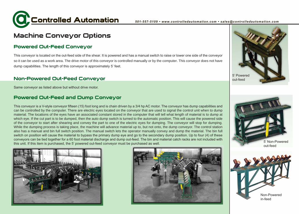
Machine Conveyor Options
Powered Out-Feed Conveyor
so it can be used as a work area. The drive motor of this conveyor is controlled manually or by the computer. This conveyor does not have
Non-Powered Out-Feed Conveyor
Powered Out-Feed and Dump Conveyor
can be controlled by the computer. There are electric eyes located on the conveyor that are used to signal the control unit when to dump material. The locations of the eyes have an associated constant stored in the computer that will tell what length of material is to dump at which eye. If the cut part is to be dumped, then the auto dump switch is turned to the automatic position. This will cause the powered side of the conveyor to start after shearing and convey the part to one of the electric eyes for dumping. The conveyor will stop for dumping. While the dumping process is taking place, the machine will advance material up to, but not onto, the dump conveyor. The control station also has a manual and bin full switch position. The manual switch lets the operator manually convey and dump the material. The bin full
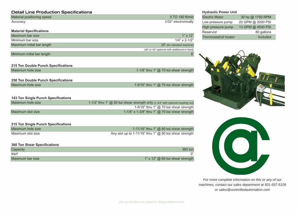
Detail Line Production Specifications
Accuracy 1/32” electronically
Hydraulic Power Unit
Thermostat/oil heater Included
For more complete information on this or any of our machines, contact our sales department at 501-557-5109
(for standard machine)
(40’ or 60’ optional with additional in-feed)
shear strength only (1-3/4” with optional coupling nut)
shear strengthshear strength
shear strength
shear strength shear strength
© 2008 Controlled Automation, Inc.
Controlled Automation specializes in the manufacture of automated structural steel drilling, punching, and shape cutting machinery. We also build material handling systems to complement each type of machine we offer. As well as new
machinery, we are the industry leader in retrofitting control systems and remanufacturing existing structural steel fabricating machinery. All machines and controls are designed and manufactured entirely in the United States of America. All software is
developed and supported in the United States of America.
501-557-5109501-557-5618 Fax
US Mail PO Box 888
Bryant, AR 72089USA
Manufacturing facility 15701 West Sardis Road
Bauxite, AR 72011USA
Recommended