IOSR Journal of Electrical and Electronics Engineering (IOSR-JEEE)
e-ISSN: 2278-1676,p-ISSN: 2320-3331, Volume 12, Issue 4 Ver. III (Jul. – Aug. 2017), PP 07-25
www.iosrjournals.org
DOI: 10.9790/1676-1204030725 www.iosrjournals.org 7 | Page
Power Quality Issues of Single Phase PFC Low Frequency Active
Converter
*Syed Mujtaba Mahdi Mudassir1, Shaik Mohammed Mukassir
2, Gulam Amer
3
1,2,3 Electrical and Electronics Dept. Deccan College of Engineering and Technology Hyderabad, India
Corresponding Author: *Syed Mujtaba Mahdi Mudassir
Abstract: The equipment connected to an power distribution network usually needs some kind of power
conditioning, typically rectification, which produces a non-sinusoidal line current due to the non-linear input
characteristic. With the steadily increasing use of such electronic equipment, line current harmonics have
become a major problem. Their adverse effects on the power system are well recognized. They include
increased magnitudes of neutral currents in three-phase systems, overheating in transformers and motors, as
well as the degradation of system waveforms. Several international standards now exist, which limit the
harmonic content due to line currents of equipment connected to electricity distribution networks. As a result,
there is the need for a Power Factor Correction - PFC. In this paper, we address several issues concerning the
application to single-phase PFC of various high-frequency switching converter topologies. The inherent PFC
properties of second order switching converters operating in Discontinuous Inductor Current Mode – DICM
are well known, and Boost converters are widely used. However, their output voltage is always higher than the
amplitude of the rectified-sinusoid input voltage. Methods for improving the efficiency of the PFC stage are
addressed. We compare several Boost-type topologies that have lower conduction losses than the combined
diode bridge and Boost converter in other words it can perform direct AC/DC conversion. Simulation results
show that the topological issues related PFC in power converter.
Index Terms: Power quality, PFC, boost converter, current mode, current harmonics. (Key words)
---------------------------------------------------------------------------------------------------------------------------------------
Date of Submission: 27-07-2017 Date of acceptance: 10-08-2017
---------------------------------------------------------------------------------------------------------------------------------------
I. Nonlinear loads and their effect on the electricity distribution network The equipment connected to an electricity distribution network usually needs some kind of power
conditioning, typically rectification, which produces a non-sinusoidal line current due to the nonlinear input
characteristic. The most significant examples of nonlinear loads are reviewed next. Line-frequency diode
rectifiers convert AC input voltage into DC output voltage in an uncontrolled manner. Single-phase diode
rectifiers are needed in relatively low power equipment that need some kind of power conditioning, such as
electronic equipment (e.g. TVs, office equipment, battery chargers, electronic ballasts) and household
appliances. For higher power, three phase diode rectifiers are used, e.g. in variable-speed drives and industrial
equipment. In both single- and three-phase rectifiers, a large filtering capacitor is connected across the rectifier
output to obtain DC output voltage with low ripple. As a consequence, the line current is non-sinusoidal. Line-
frequency phase-controlled rectifiers are used for controlling the transfer of energy between the AC input and
the adjustable DC output.
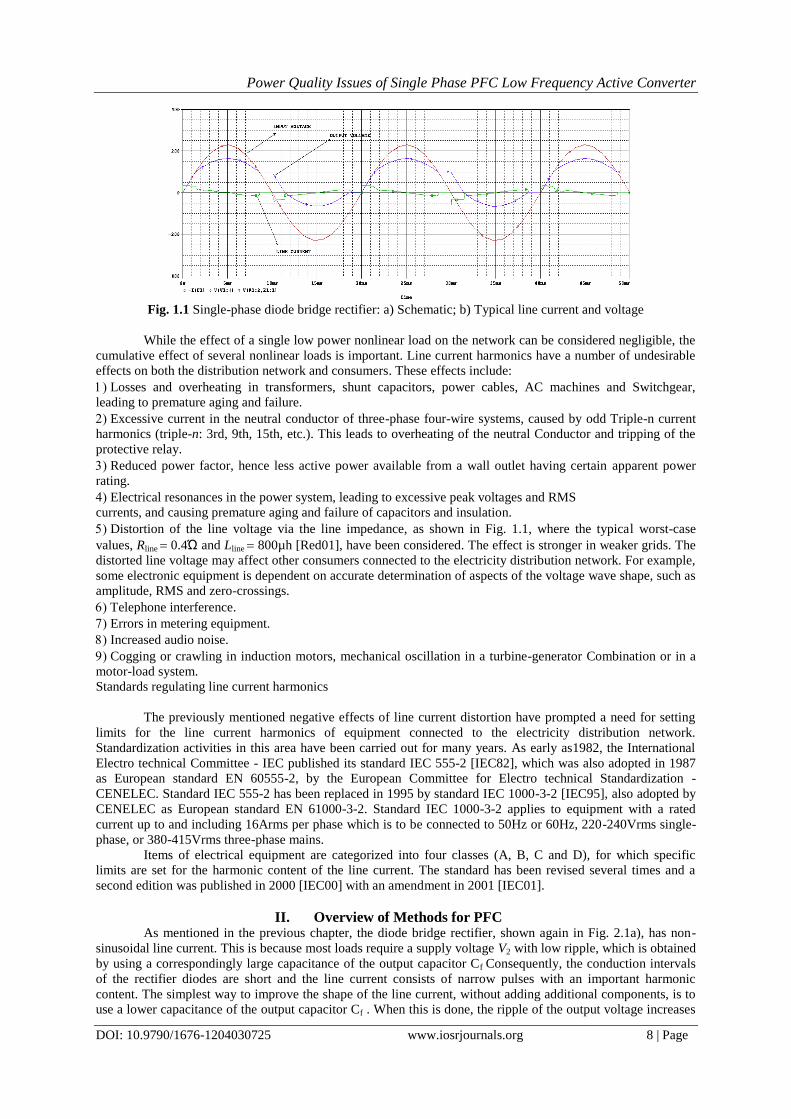
In most of these cases, the amplitude of odd harmonics of the line current is considerable with respect
to the fundamental. As an example, a single-phase diode rectifier is presented in Fig. 1.1, together with its line
current and voltage waveforms. The odd harmonics of the line current, normalized to the fundamental, are
shown in the same figure. The normalized amplitudes of the 3rd, 5th, 7th and 9th harmonics are significant.
Power Quality Issues of Single Phase PFC Low Frequency Active Converter
DOI: 10.9790/1676-1204030725 www.iosrjournals.org 8 | Page
Fig. 1.1 Single-phase diode bridge rectifier: a) Schematic; b) Typical line current and voltage
While the effect of a single low power nonlinear load on the network can be considered negligible, the
cumulative effect of several nonlinear loads is important. Line current harmonics have a number of undesirable
effects on both the distribution network and consumers. These effects include:
Losses and overheating in transformers, shunt capacitors, power cables, AC machines and Switchgear,
leading to premature aging and failure.
Excessive current in the neutral conductor of three-phase four-wire systems, caused by odd Triple-n current
harmonics (triple-n: 3rd, 9th, 15th, etc.). This leads to overheating of the neutral Conductor and tripping of the
protective relay.
Reduced power factor, hence less active power available from a wall outlet having certain apparent power
rating.
Electrical resonances in the power system, leading to excessive peak voltages and RMS
currents, and causing premature aging and failure of capacitors and insulation.
Distortion of the line voltage via the line impedance, as shown in Fig. 1.1, where the typical worst-case
values, Rline 0.4Ώ and Lline 800µh [Red01], have been considered. The effect is stronger in weaker grids. The
distorted line voltage may affect other consumers connected to the electricity distribution network. For example,
some electronic equipment is dependent on accurate determination of aspects of the voltage wave shape, such as
amplitude, RMS and zero-crossings.
Telephone interference.
Errors in metering equipment.
Increased audio noise.
Cogging or crawling in induction motors, mechanical oscillation in a turbine-generator Combination or in a
motor-load system.
Standards regulating line current harmonics
The previously mentioned negative effects of line current distortion have prompted a need for setting
limits for the line current harmonics of equipment connected to the electricity distribution network.
Standardization activities in this area have been carried out for many years. As early as1982, the International
Electro technical Committee - IEC published its standard IEC 555-2 [IEC82], which was also adopted in 1987
as European standard EN 60555-2, by the European Committee for Electro technical Standardization -
CENELEC. Standard IEC 555-2 has been replaced in 1995 by standard IEC 1000-3-2 [IEC95], also adopted by
CENELEC as European standard EN 61000-3-2. Standard IEC 1000-3-2 applies to equipment with a rated
current up to and including 16Arms per phase which is to be connected to 50Hz or 60Hz, 220-240Vrms single-
phase, or 380-415Vrms three-phase mains.
Items of electrical equipment are categorized into four classes (A, B, C and D), for which specific
limits are set for the harmonic content of the line current. The standard has been revised several times and a
second edition was published in 2000 [IEC00] with an amendment in 2001 [IEC01].
II. Overview of Methods for PFC As mentioned in the previous chapter, the diode bridge rectifier, shown again in Fig. 2.1a), has non-
sinusoidal line current. This is because most loads require a supply voltage V2 with low ripple, which is obtained
by using a correspondingly large capacitance of the output capacitor Cf Consequently, the conduction intervals
of the rectifier diodes are short and the line current consists of narrow pulses with an important harmonic
content. The simplest way to improve the shape of the line current, without adding additional components, is to
use a lower capacitance of the output capacitor Cf . When this is done, the ripple of the output voltage increases
Power Quality Issues of Single Phase PFC Low Frequency Active Converter
DOI: 10.9790/1676-1204030725 www.iosrjournals.org 9 | Page
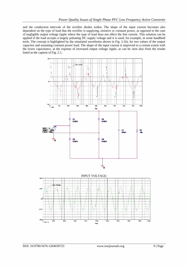
and the conduction intervals of the rectifier diodes widen. The shape of the input current becomes also
dependent on the type of load that the rectifier is supplying, resistive or constant power, as opposed to the case
of negligible output voltage ripple where the type of load does not affect the line current. This solution can be
applied if the load accepts a largely pulsating DC supply voltage and it is used, for example, in some handheld
tools. The concept is highlighted by the simulated waveforms shown in Fig. 2.1b), for two values of the output
capacitor and assuming constant power load. The shape of the input current is improved to a certain extent with
the lower capacitance, at the expense of increased output voltage ripple, as can be seen also from the results
listed in the caption of Fig. 2.1.
INPUT VOLTAGE:
Power Quality Issues of Single Phase PFC Low Frequency Active Converter
DOI: 10.9790/1676-1204030725 www.iosrjournals.org 10 | Page
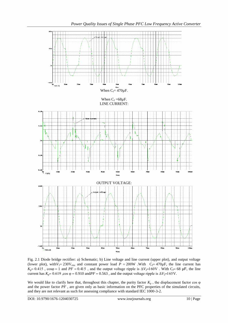
When Cf= 470µF.
When Cf =68µF.
LINE CURRENT:
OUTPUT VOLTAGE:
Fig. 2.1 Diode bridge rectifier: a) Schematic; b) Line voltage and line current (upper plot), and output voltage
(lower plot), withV1230Vrms and constant power load P 200W .With Cf470µF, the line current has
Kp0.415 , cosφ1 and PF , and the output voltage ripple is ΔV2V . With Cf68 µF, the line
current has Kp0.619 ,cos φ0.910 andPF 0.563 , and the output voltage ripple is ΔV2V.
We would like to clarify here that, throughout this chapter, the purity factor Kp , the displacement factor cos φ
and the power factor PF , are given only as basic information on the PFC properties of the simulated circuits,
and they are not relevant as such for assessing compliance with standard IEC 1000-3-2.
Power Quality Issues of Single Phase PFC Low Frequency Active Converter
DOI: 10.9790/1676-1204030725 www.iosrjournals.org 11 | Page
The method presented above has severe limitations: it does not reduce substantially the harmonic currents and
the output voltage ripple is large, which is not acceptable in most of the cases. Several other methods to reduce
the harmonic content of the line current in single-phase systems exist, and an overview of the representative
ones is presented next.
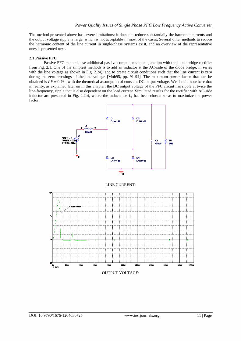
2.1 Passive PFC
Passive PFC methods use additional passive components in conjunction with the diode bridge rectifier
from Fig. 2.1. One of the simplest methods is to add an inductor at the AC-side of the diode bridge, in series
with the line voltage as shown in Fig. 2.2a), and to create circuit conditions such that the line current is zero
during the zero-crossings of the line voltage [Moh95, pp. 91-94]. The maximum power factor that can be
obtained is PF 0.76 , with the theoretical assumption of constant DC output voltage. We should note here that
in reality, as explained later on in this chapter, the DC output voltage of the PFC circuit has ripple at twice the
line-frequency, ripple that is also dependent on the load current. Simulated results for the rectifier with AC-side
inductor are presented in Fig. 2.2b), where the inductance La has been chosen so as to maximize the power
factor.
LINE CURRENT:
OUTPUT VOLTAGE:
Power Quality Issues of Single Phase PFC Low Frequency Active Converter
DOI: 10.9790/1676-1204030725 www.iosrjournals.org 12 | Page
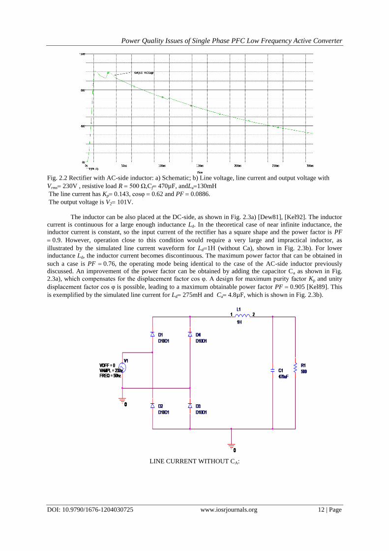
Fig. 2.2 Rectifier with AC-side inductor: a) Schematic; b) Line voltage, line current and output voltage with
Vrms230V , resistive load R 500 Ω,Cf470µF, andLa130mH
The line current has Kp0.143, cosφ0.62 and PF 0.0886.
The output voltage is V2101V.
The inductor can be also placed at the DC-side, as shown in Fig. 2.3a) [Dew81], [Kel92]. The inductor
current is continuous for a large enough inductance Ld. In the theoretical case of near infinite inductance, the
inductor current is constant, so the input current of the rectifier has a square shape and the power factor is PF
0.9. However, operation close to this condition would require a very large and impractical inductor, as
illustrated by the simulated line current waveform for Ld1H (without Ca), shown in Fig. 2.3b). For lower
inductance Ld, the inductor current becomes discontinuous. The maximum power factor that can be obtained in
such a case is PF 0.76, the operating mode being identical to the case of the AC-side inductor previously
discussed. An improvement of the power factor can be obtained by adding the capacitor Ca as shown in Fig.
2.3a), which compensates for the displacement factor cos φ. A design for maximum purity factor Kp and unity
displacement factor cos φis possible, leading to a maximum obtainable power factor PF 0.905 [Kel89]. This
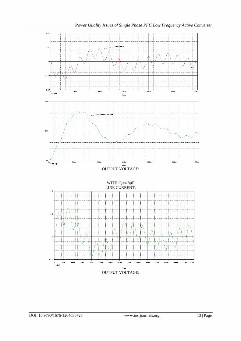
is exemplified by the simulated line current for Ld275mH and Ca4.8µF, which is shown in Fig. 2.3b).
LINE CURRENT WITHOUT CA:
Power Quality Issues of Single Phase PFC Low Frequency Active Converter
DOI: 10.9790/1676-1204030725 www.iosrjournals.org 13 | Page
OUTPUT VOLTAGE:
WITH Ca=4.8µF
LINE CURRENT:
OUTPUT VOLTAGE:
Power Quality Issues of Single Phase PFC Low Frequency Active Converter
DOI: 10.9790/1676-1204030725 www.iosrjournals.org 14 | Page
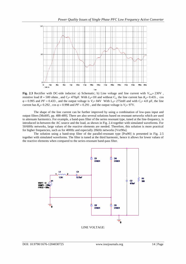
Fig. 2.3 Rectifier with DC-side inductor: a) Schematic; b) Line voltage and line current with Vrms230V ,
resistive load R 500 ohms, and Cf470µF. With Ld1H and without Ca, the line current has Kp0.435 , cos
φ0.995 and PF 0.433 , and the output voltage is V284V With Ld275mH and with Ca4.8 µF, the line
current has Kp0.292 , cos φ0.998 and PF 0.291 , and the output voltage is V297V.
The shape of the line current can be further improved by using a combination of low-pass input and
output filters [Moh95, pp. 488-489]. There are also several solutions based on resonant networks which are used
to attenuate harmonics. For example, a band-pass filter of the series resonant type, tuned at the line-frequency, is
introduced in-between the AC source and the load, as shown in Fig. 2.4 together with simulated waveforms. For
50/60Hz networks, large values of the reactive elements are needed. Therefore, this solution is more practical
for higher frequencies, such as for 400Hz and especially 20kHz networks [Vor90a].
The solution using a band-stop filter of the parallel-resonant type [Pra90] is presented in Fig. 2.5
together with simulated waveforms. The filter is tuned at the third harmonic, hence it allows for lower values of
the reactive elements when compared to the series-resonant band-pass filter.
LINE VOLTAGE:
Power Quality Issues of Single Phase PFC Low Frequency Active Converter
DOI: 10.9790/1676-1204030725 www.iosrjournals.org 15 | Page
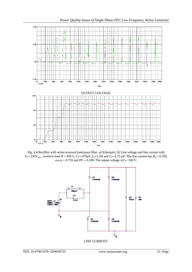
OUTPUT VOLTAGE:
Fig. 2.4 Rectifier with series-resonant band-pass filter: a) Schematic; b) Line voltage and line current with
V1230Vrms , resistive load R 500 ©, Cf 470µF, Ls1.5H and Cs6.75 µF. The line current has Kp 0.250,
cos φ0.755 and PF 0.189. The output voltage isV2100 V.
LINE CURRENT:
Power Quality Issues of Single Phase PFC Low Frequency Active Converter
DOI: 10.9790/1676-1204030725 www.iosrjournals.org 16 | Page
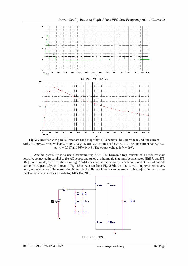
OUTPUT VOLTAGE:
Fig. 2.5 Rectifier with parallel-resonant band-stop filter: a) Schematic; b) Line voltage and line current
withV1230Vrms, resistive load R 500 ©,Cf470µF, Lp240mH and Cp4.7µF. The line current has Kp0.2,
cos φ0.717 and PF 0.143 . The output voltage is V29V.
Another possibility is to use a harmonic trap filter. The harmonic trap consists of a series resonant
network, connected in parallel to the AC source and tuned at a harmonic that must be attenuated [Eri97, pp. 575-
582]. For example, the filter shown in Fig. 2.6a)-b) has two harmonic traps, which are tuned at the 3rd and 5th
harmonic, respectively, as shown in Fig. 2.6c). As seen from Fig. 2.6d), the line current improvement is very
good, at the expense of increased circuit complexity. Harmonic traps can be used also in conjunction with other
reactive networks, such as a band-stop filter [Red91].
LINE CURRENT:
Power Quality Issues of Single Phase PFC Low Frequency Active Converter
DOI: 10.9790/1676-1204030725 www.iosrjournals.org 17 | Page
OUTPUT VOLTAGE:
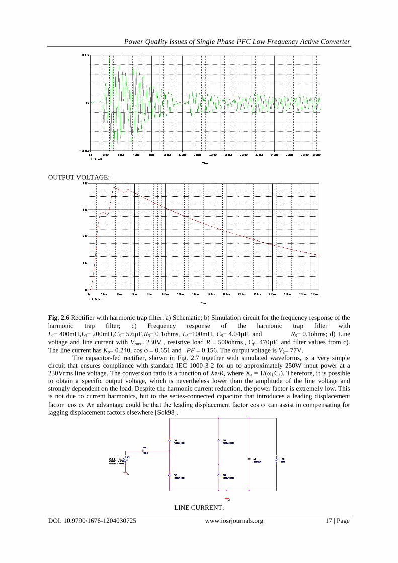
Fig. 2.6 Rectifier with harmonic trap filter: a) Schematic; b) Simulation circuit for the frequency response of the
harmonic trap filter; c) Frequency response of the harmonic trap filter with
L1400mH,L3200mH,C35.6µF,R30.1ohms, L5100mH, C54.04µF, and R50.1ohms; d) Line
voltage and line current with Vrms230V , resistive load R 500ohms, Cf470µF, and filter values from c).
The line current has Kp0.240, cos φ0.651 and PF 0.156. The output voltage is V277V. The capacitor-fed rectifier, shown in Fig. 2.7 together with simulated waveforms, is a very simple
circuit that ensures compliance with standard IEC 1000-3-2 for up to approximately 250W input power at a
230Vrms line voltage. The conversion ratio is a function of Xa/R, where Xa = 1/(ωLCa). Therefore, it is possible
to obtain a specific output voltage, which is nevertheless lower than the amplitude of the line voltage and
strongly dependent on the load. Despite the harmonic current reduction, the power factor is extremely low. This
is not due to current harmonics, but to the series-connected capacitor that introduces a leading displacement
factor cos φ. An advantage could be that the leading displacement factor cos φcan assist in compensating for
lagging displacement factors elsewhere [Sok98].
LINE CURRENT:
Power Quality Issues of Single Phase PFC Low Frequency Active Converter
DOI: 10.9790/1676-1204030725 www.iosrjournals.org 18 | Page
OUTPUT VOLTAGE:
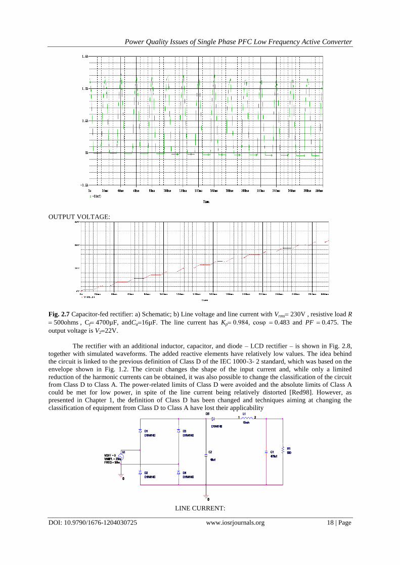
Fig. 2.7 Capacitor-fed rectifier: a) Schematic; b) Line voltage and line current with Vrms230V , resistive load R
500ohms, Cf4700µF, andCa16µF. The line current has Kp0.984, cosφ0.483 and PF 0.475. The
output voltage is V222V.
The rectifier with an additional inductor, capacitor, and diode – LCD rectifier – is shown in Fig. 2.8,
together with simulated waveforms. The added reactive elements have relatively low values. The idea behind
the circuit is linked to the previous definition of Class D of the IEC 1000-3- 2 standard, which was based on the
envelope shown in Fig. 1.2. The circuit changes the shape of the input current and, while only a limited
reduction of the harmonic currents can be obtained, it was also possible to change the classification of the circuit
from Class D to Class A. The power-related limits of Class D were avoided and the absolute limits of Class A
could be met for low power, in spite of the line current being relatively distorted [Red98]. However, as
presented in Chapter 1, the definition of Class D has been changed and techniques aiming at changing the
classification of equipment from Class D to Class A have lost their applicability
LINE CURRENT:
Power Quality Issues of Single Phase PFC Low Frequency Active Converter
DOI: 10.9790/1676-1204030725 www.iosrjournals.org 19 | Page
OUTPUT VOLTAGE:
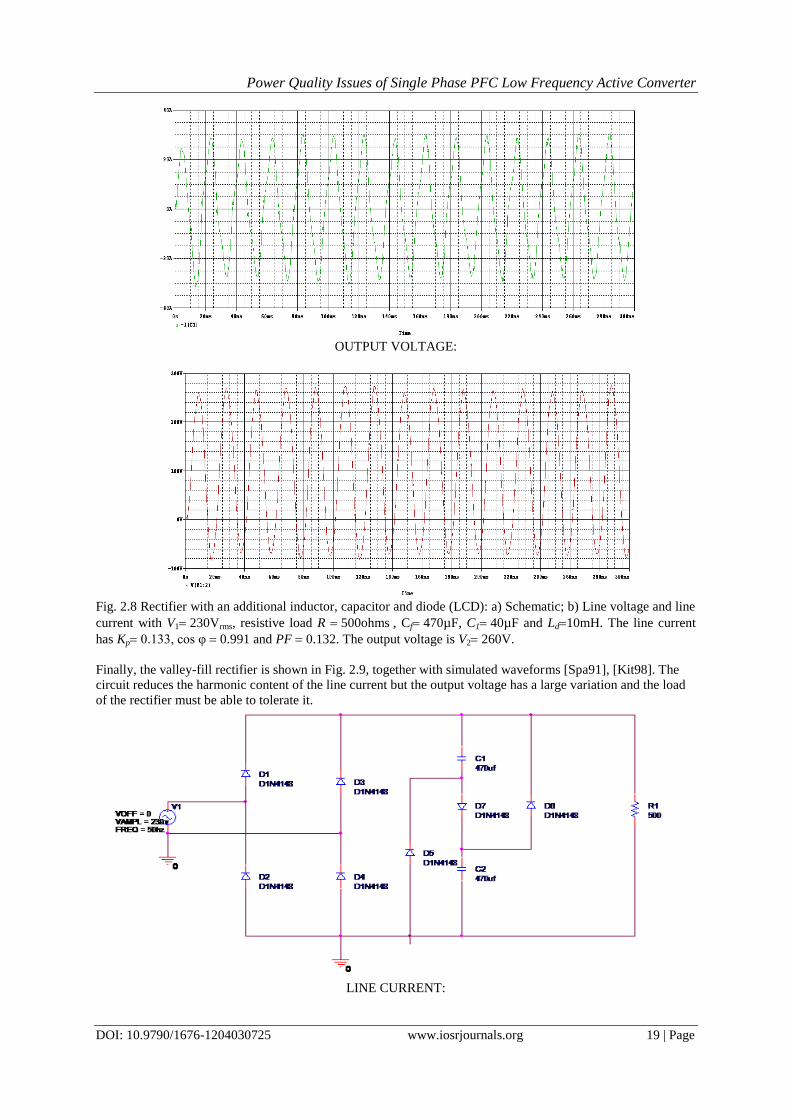
Fig. 2.8 Rectifier with an additional inductor, capacitor and diode (LCD): a) Schematic; b) Line voltage and line
current with V1230Vrms, resistive load R 500ohms, Cf470µF, C140µF and Ld10mH. The line current
has Kp0.133, cos φ0.991 and PF 0.132. The output voltage is V2260V.
Finally, the valley-fill rectifier is shown in Fig. 2.9, together with simulated waveforms [Spa91], [Kit98]. The
circuit reduces the harmonic content of the line current but the output voltage has a large variation and the load
of the rectifier must be able to tolerate it.
LINE CURRENT:
Power Quality Issues of Single Phase PFC Low Frequency Active Converter
DOI: 10.9790/1676-1204030725 www.iosrjournals.org 20 | Page
OUTPUT VOLTAGE:
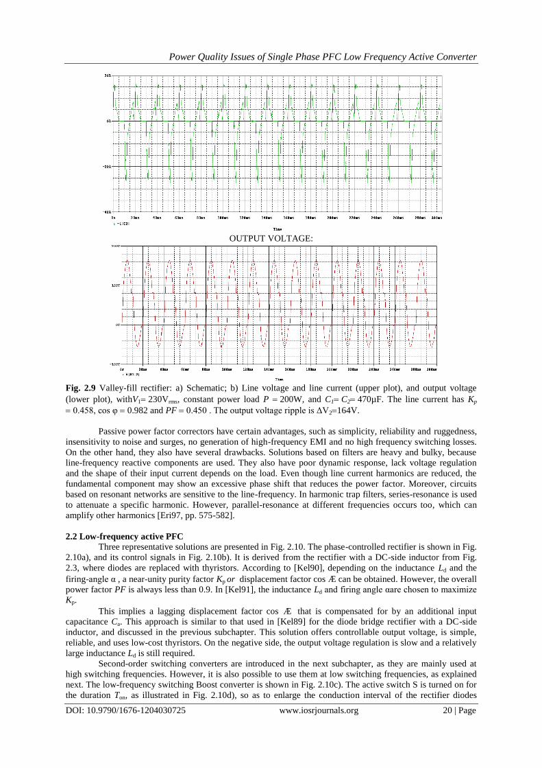
Fig. 2.9 Valley-fill rectifier: a) Schematic; b) Line voltage and line current (upper plot), and output voltage
(lower plot), withV1230Vrms, constant power load P 200W, and C1C2470µF. The line current has Kp
0.458, cos φ0.982 and PF 0.450 . The output voltage ripple is ΔV2164V.
Passive power factor correctors have certain advantages, such as simplicity, reliability and ruggedness,
insensitivity to noise and surges, no generation of high-frequency EMI and no high frequency switching losses.
On the other hand, they also have several drawbacks. Solutions based on filters are heavy and bulky, because
line-frequency reactive components are used. They also have poor dynamic response, lack voltage regulation
and the shape of their input current depends on the load. Even though line current harmonics are reduced, the
fundamental component may show an excessive phase shift that reduces the power factor. Moreover, circuits
based on resonant networks are sensitive to the line-frequency. In harmonic trap filters, series-resonance is used
to attenuate a specific harmonic. However, parallel-resonance at different frequencies occurs too, which can
amplify other harmonics [Eri97, pp. 575-582].
2.2 Low-frequency active PFC
Three representative solutions are presented in Fig. 2.10. The phase-controlled rectifier is shown in Fig.
2.10a), and its control signals in Fig. 2.10b). It is derived from the rectifier with a DC-side inductor from Fig.
2.3, where diodes are replaced with thyristors. According to [Kel90], depending on the inductance Ld and the
firing-angle α, a near-unity purity factor Kp or displacement factor cosÆcan be obtained. However, the overall
power factor PF is always less than 0.9. In [Kel91], the inductance Ld and firing angle αare chosen to maximize
Kp.
This implies a lagging displacement factor cosÆ that is compensated for by an additional input
capacitance Ca. This approach is similar to that used in [Kel89] for the diode bridge rectifier with a DC-side
inductor, and discussed in the previous subchapter. This solution offers controllable output voltage, is simple,
reliable, and uses low-cost thyristors. On the negative side, the output voltage regulation is slow and a relatively
large inductance Ld is still required.
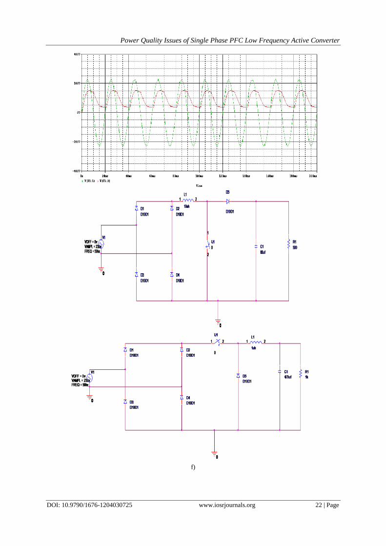
Second-order switching converters are introduced in the next subchapter, as they are mainly used at
high switching frequencies. However, it is also possible to use them at low switching frequencies, as explained
next. The low-frequency switching Boost converter is shown in Fig. 2.10c). The active switch S is turned on for
the duration Ton, as illustrated in Fig. 2.10d), so as to enlarge the conduction interval of the rectifier diodes
Power Quality Issues of Single Phase PFC Low Frequency Active Converter
DOI: 10.9790/1676-1204030725 www.iosrjournals.org 21 | Page
[Zuc97]. It is also possible to have multiple switching’s per half line-cycle, at low switching frequency, in order
to improve the shape of the line current [Red91]. Nevertheless, the line current has a considerable ripple.
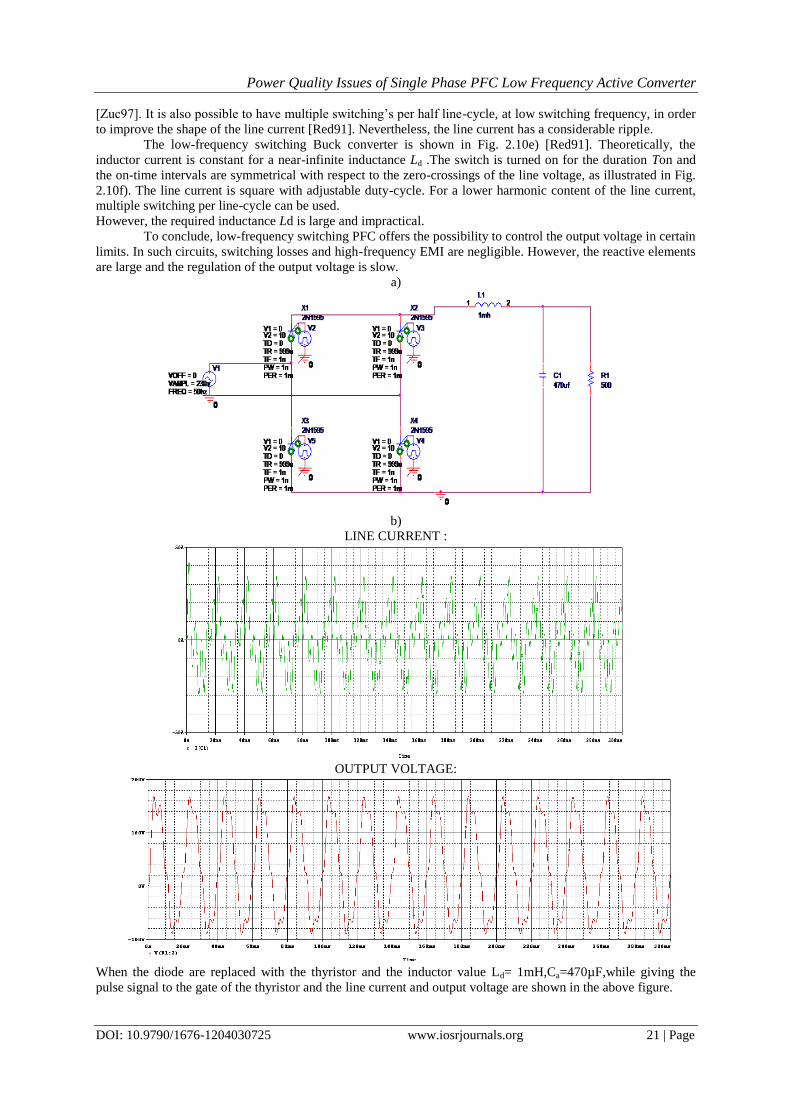
The low-frequency switching Buck converter is shown in Fig. 2.10e) [Red91]. Theoretically, the
inductor current is constant for a near-infinite inductance Ld .The switch is turned on for the duration Ton and
the on-time intervals are symmetrical with respect to the zero-crossings of the line voltage, as illustrated in Fig.
2.10f). The line current is square with adjustable duty-cycle. For a lower harmonic content of the line current,
multiple switching per line-cycle can be used.
However, the required inductance Ld is large and impractical.
To conclude, low-frequency switching PFC offers the possibility to control the output voltage in certain
limits. In such circuits, switching losses and high-frequency EMI are negligible. However, the reactive elements
are large and the regulation of the output voltage is slow.
a)
b)
LINE CURRENT :
OUTPUT VOLTAGE:
When the diode are replaced with the thyristor and the inductor value Ld= 1mH,Ca=470µF,while giving the
pulse signal to the gate of the thyristor and the line current and output voltage are shown in the above figure.
Power Quality Issues of Single Phase PFC Low Frequency Active Converter
DOI: 10.9790/1676-1204030725 www.iosrjournals.org 22 | Page
f)
Power Quality Issues of Single Phase PFC Low Frequency Active Converter
DOI: 10.9790/1676-1204030725 www.iosrjournals.org 23 | Page
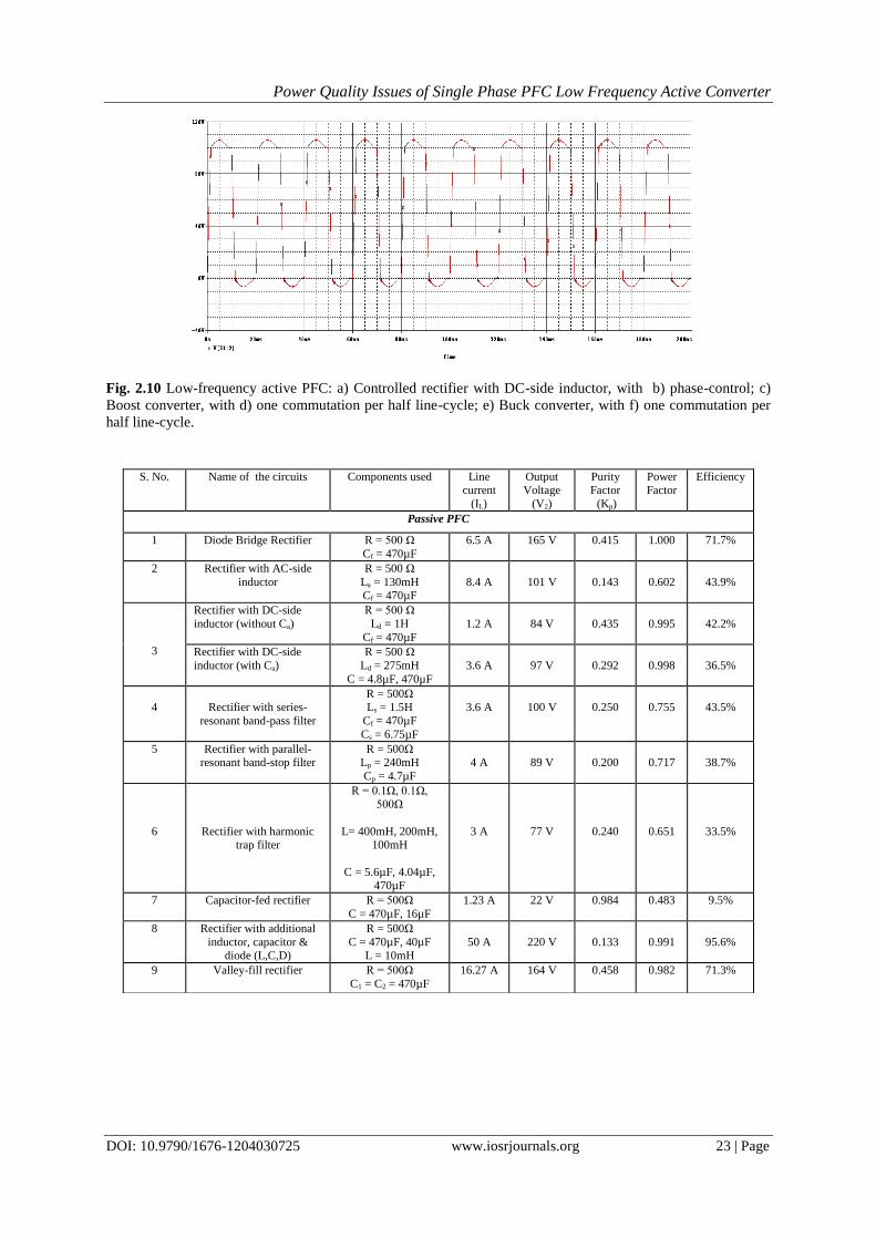
Fig. 2.10 Low-frequency active PFC: a) Controlled rectifier with DC-side inductor, with b) phase-control; c)
Boost converter, with d) one commutation per half line-cycle; e) Buck converter, with f) one commutation per
half line-cycle.
S. No. Name of the circuits Components used Line current
(IL)
Output Voltage
(V2)
Purity Factor
(Kp)
Power Factor
Efficiency
Passive PFC
1 Diode Bridge Rectifier R = 500 Ω
Cf = 470µF
6.5 A 165 V 0.415 1.000 71.7%
2 Rectifier with AC-side
inductor
R = 500 Ω
La = 130mH Cf = 470µF
8.4 A
101 V
0.143
0.602
43.9%
3
Rectifier with DC-side
inductor (without Ca)
R = 500 Ω
Ld = 1H
Cf = 470µF
1.2 A
84 V
0.435
0.995
42.2%
Rectifier with DC-side
inductor (with Ca)
R = 500 Ω
Ld = 275mH
C = 4.8µF, 470µF
3.6 A
97 V
0.292
0.998
36.5%
4
Rectifier with series-
resonant band-pass filter
R = 500Ω Ls = 1.5H
Cf = 470µF
Cs = 6.75µF
3.6 A
100 V
0.250
0.755
43.5%
5 Rectifier with parallel-resonant band-stop filter
R = 500Ω Lp = 240mH
Cp = 4.7µF
4 A
89 V
0.200
0.717
38.7%
6
Rectifier with harmonic trap filter
R = 0.1Ω, 0.1Ω,
500Ω
L= 400mH, 200mH, 100mH
C = 5.6µF, 4.04µF, 470µF
3 A
77 V
0.240
0.651
33.5%
7 Capacitor-fed rectifier R = 500Ω
C = 470µF, 16µF
1.23 A 22 V 0.984 0.483 9.5%
8 Rectifier with additional
inductor, capacitor & diode (L,C,D)
R = 500Ω
C = 470µF, 40µF L = 10mH
50 A
220 V
0.133
0.991
95.6%
9 Valley-fill rectifier R = 500Ω
C1 = C2 = 470µF
16.27 A 164 V 0.458 0.982 71.3%
Power Quality Issues of Single Phase PFC Low Frequency Active Converter
DOI: 10.9790/1676-1204030725 www.iosrjournals.org 24 | Page
References [1]. [Bar98] L. Barreto, A. Pereira, V. Farias, L. de Freitas, J. Vieira Jr., “A Boost converter associated with a new non-dissipative
snubber”, in Proc. of IEEE Applied Power Electronics Conference, APEC’98, pp. 1077-1083, 1998.
[2]. [Brk92] M.Brkovic, S. Cuk, “input current shaper using Cuk converter”, in Proc. of IEEE International Telecommunications Energy
Conference, INTELEC’92, pp. 532-539, 1992.
[3]. [Cho98] J. Cho, J. Baek, D. Yoo, H. Lee, “Reduced conduction loss zero-voltage-transition power factor correction converter with low cost”, IEEE Trans. on Industrial Electronics, vol. 45, no. 3, pp. 395-400, June 1998.
[4]. [Cuk77a] S. Cuk, R.D. Middlebrook, “A new optimum topology switching DC-to-DC converter”, in Proc. of IEEE Power
Electronics Specialists Conference, PESC’77, 1977. Reprinted in Advances in switched-mode power conversion, Vol. I&II, pp. 311-330. Pasadena, CA, USA, TESLAco, 1983.
[5]. [Cuk77b] S.Cuk, R. D. Middlebrook, “Coupled-inductor and other extensions of a new optimum topology switching DC-to-DC
converter”, in Proc. of IEEE Industry Applications Society Annual Meeting, 1977. Reprinted in Advances in switched-mode power conversion, Vol. I&II, pp. 331-347. Pasadena, CA, USA, TESLAco, 1983.
[6]. [Dew81] S. B. Dewan, “Optimum input and output filters for single-phase rectifier power supply”, IEEE Trans. on Industry
Applications, vol. IA17, no. 3, pp. 282-288, May/June 1981. [7]. [Dix90a] L. Dixon, “Average current mode control of switching power supplies”, in Unitrode Power Supply Design Seminar
Manual, SEM-700, 1990. Reprinted in the Unitrode Applications Handbook (IC 1051), Application note U-140, pp. 3-356 – 3-369,
1997. [8]. [Dix90b] L. Dixon, “High power factor switching pre-regulator design optimization”, in Unitrode Power Supply Design Seminar
Manual, SEM-700, 1990. Reprinted in the Unitrode Power Supply Design Seminar Manual, SEM-1000, pp. I3-1 – I3-12, 1994.
[9]. [Dix93a] L. Dixon, “High power factor pre-regulator using the SEPIC converter”, in Unitrode Power Supply Design Seminar Manual, SEM-900, 1993. Reprinted in the Unitrode Power Supply Design Seminar Manual, SEM-1000, pp. I2-1 – I2-12, 1994.
[10]. [Dix93b] L. Dixon, “Control loop design - SEPIC pre-regulator example”, in Unitrode Power Supply Design Seminar Manual,
SEM-900, 1993. Reprinted in the Unitrode Power Supply Design Seminar Manual, SEM-1000, pp. C3-1 – C3-7, 1994. [11]. [End92] H. Endo, T. Yamashita, T. Sugiura, “A high-power factor Buck converter”, in Proc. Of IEEE Power Electronics Specialists
Conference, PESC’92, pp. 1072-1076, 1992.
[12]. [Eri97] R. W. Erickson, Fundamentals of Power Electronics. New York, NY, USA, Chapman Hall, 1997. [13]. [Fre93] L. C. de Freitas, P. R. C. Gomes, “A high-power high-efficiency ZCS-ZVS-PWM Buck converter using a feedback
resonant circuit”, in Proc. of IEEE Power Electronics Specialists Conference, PESC’93, pp. 330-336, 1993.
[14]. [Gha93] M. C. Ghanem, K. Al-Haddad, G. Roy, “A new single phase buck-boost converter with unity power factor”, in Conference Record of the 1993 IEEE Industry Applications Society Annual Meeting, IAS’93, pp. 785-792, 1993.
[15]. [Gla95] J. S. Glaser, A. F. Witulski, “Design issues for high power factor AC-DC converter systems”, in Proc. of IEEE Power
Electronics Specialists Conference, PESC’95, pp. 542-548, 1995. [16]. [Gri97] V. Grigore, J. Kyyrä, “A new zero-voltage-transition PWM switching cell”, in Proc. Of the 1997 Finnish Workshop on
Power and Industrial Electronics, FINPIE/97, pp. 79-84, 1997.
[17]. [Hua94] G. Hua, C. S. Leu, Y. Jiang, F. C. Lee, “Novel zero-voltage-transition PWM converters”, IEEE Trans. on Power Electronics, vol. 9, no. 2, pp. 213-219, Mar. 1994.
[18]. [Hua95] G. Hua, F. C. Lee, “Soft-switching techniques in PWM converters”, IEEE Trans. On Industrial Electronics, vol. 42, no. 6,
pp. 595-603, Dec. 1995. [19]. [Hub97] L. Huber, M. Jovanovic, “Single-stage, single-switch, isolated power supply technique with input-current shaping and fast
output-voltage regulation for universal input-voltagerange applications”, in Proc. of IEEE Applied Power Electronics Conference,
APEC’97, pp. 272-280, 1997. [20]. [IEC00] IEC 61000-3-2 (2000-08) Ed. 2: “Electromagnetic compatibility (EMC) - Part 3-2: Limits - Limits for harmonic current
emissions (equipment input current 16A per phase)”, IEC, 2000.
[21]. [IEC01] IEC 61000-3-2-am1 (2001-08) Amendment 1: “Electromagnetic compatibility (EMC) -Part 3-2: Limits - Limits for
harmonic current emissions (equipment input current 16A per phase)”, IEC, 2001.
[22]. [IEC82] IEC 555-2: “Disturbances in supply systems caused by household appliances and similar electrical equipment – Part 2:
Harmonics”, IEC, 1982. [23]. [IEC95] IEC 1000-3-2 (1995-3) Ed. 1: “Electromagnetic compatibility (EMC) - Part 3-2: Limits -Limits for harmonic current
emissions (equipment input current 16A per phase)”, IEC, 1995.
[24]. [IEC98] IEC/TS 61000-3-4 (1998-10) Ed. 1: “Electromagnetic compatibility (EMC) - Part 3-4: Limits - Limitation of emission of harmonic currents in low-voltage power supply systems for equipment with rated current greater than 16A”, IEC, 1998.
[25]. [IEE92] IEEE Standard 519-1992: “IEEE Recommended practices and requirements for harmonic control in electrical power
systems”, IEEE, 1992.
[26]. [IEE96] IEEE Standard 100-1996: “The IEEE Standard dictionary of electrical and electronics terms”, sixth edition, IEEE, 1996.
[27]. [Ism92] E. Ismail, R. W. Erickson, “A single transistor three phase resonant switch for high quality rectification”, in Proc. of IEEE
Power Electronics Specialists Conference,PESC’92, pp. 1341-1351, 1992. [28]. [Jan92] Y. Jang, R. W: Erickson, “Physical origins of input filter oscillations in current programmed converters”, IEEE
Transactions on Power Electronics, vol. 7, no. 4, pp. 725-733, Oct. 1992.
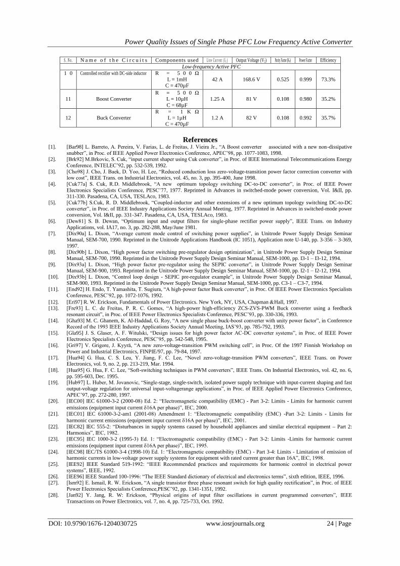
S . N o . N a m e o f t h e C i r c u i t s Components used L i n e C u r r e n t ( I L ) Output Voltage (V2) Purity Factor (KP) Power Factor Efficiency
Low-frequency Active PFC
1 0 Controlled rectifier with DC-side inductor R = 5 0 0 Ω
L = 1mH C = 470µF
42 A
168.6 V
0.525
0.999
73.3%
11
Boost Converter
R = 5 0 0 Ω L = 10µH
C = 68µF
1.25 A
81 V
0.108
0.980
35.2%
12
Buck Converter
R = 1 K Ω L = 1µH
C = 470µF
1.2 A
82 V
0.108
0.992
35.7%
Power Quality Issues of Single Phase PFC Low Frequency Active Converter
DOI: 10.9790/1676-1204030725 www.iosrjournals.org 25 | Page
[29]. [Jan98] Y. Jang, M .Javonovic, “ Design consideration and performance evaluation of a 3KW,soft-switched Boost converter with
active snubber”, in Proc. of IEEE InternationalTelecommunications Energy Conference, INTELEC’98, pp. 678-684, 1998. [30]. [Jay98] N. Jayaram, D. Maksimovic, “Power Factor correctors based on coupled-inductor SEPIC and Cuk converters with nonlinear
-carrier control”, in Proc. of IEEE Applied Power Electronics Conference, APEC’98, pp. 468-474, 1998. [31]. [Jou96] G. B. Joung, “New soft switched PWM converter”, in Proc. of IEEE Power Electronics Specialists Conference, PESC’96,
pp. 63-68, 1996.
[32]. [Kel89] A. W. Kelley, W. F. Yadusky, “Rectifier design for minimum line current harmonics and maximum power factor”, in Proc. of IEEE Applied Power Electronics Conference,APEC’89, pp. 13-22, 1989.
[33]. [Kel90] A. W. Kelley, W. F. Yadusky, “Phase-controlled rectifier line-current harmonics and power factor as a function of firing
angle and output filter inductance”, in Proc. of IEEEApplied Power Electronics Conference, APEC’90, pp. 588-597, 1990. [34]. [Kel91] A. W. Kelley, M. A. Hallouda, M. D. Moore, J. L. Nance, “Near-unity-power-factor single-phase ac-to-dc converter using a
phase-controlled rectifier”, in Proc. of IEEEApplied Power Electronics Conference, APEC’91, pp. 387-392, 1991.
[35]. [Kel92] A. W. Kelley, W. F. Yadusky, “Rectifier design for minimum line-current harmonics and maximum power factor”, IEEE Trans. on Power Electronics, vol. 7, no. 2, pp. 332-341, Apr. 1992.
[36]. [Kit98] K. Kit Sum, “Improved valley-fill passive power factor correction current shaper approaches IEC specification limits”,
PCIM Magazine, Feb. 1998, pp. 42-51. [Kol94] J. W. Kolar, F. C. Zach, “A novel three-phase utility interface minimizing line
current harmonics of high-power telecommunications rectifier modules”, Proc. of IEEEInternational Telecommunications Energy
Conference, INTELEC’94, pp. 367-374, 1994.
[37]. [Kol97] J. W. Kolar, H. Sree, N. Mohan, F. C. Zach, “Novel aspects of an application of ‘zero’- ripple techniques to basic converter topologies”, in Proc. of IEEE Power ElectronicsSpecialists Conference, PESC’97, pp. 796-803, 1997.
[38]. [Kre98] P. T. Krein, Elements of Power Electronics. New York, NY, USA, Oxford University Press, 1998.
[39]. [Lee97] Y. S. Lee, S. J. Wang, S. Y. R. Hui, “Modeling, analysis, and application of Buckconverters in discontinuous-input-voltage mode operation”, IEEE Trans. on PowerElectronics, vol. 12, no. 2, pp. 350-360, March 1997.
[40]. [Lev97] H. Levy, I. Zafrany, G. Ivensky, S. Ben-Yaakov, “Analysis and evaluation of a lossless turn-on snubber”, in Proc. of IEEE
Applied Power Electronics Conference, APEC’97,pp. 757-763, 1997. [41]. [Lin97] B. Lin, Y. S. Lee, “Power-Factor correction using Cuk converters in Discontinuous- capacitor-voltage mode operation”,
IEEE Trans. on Industrial Electronics, vol. 44, no. 5, pp. 648-653, Oct. 1997.
[42]. [Mad92] M. Madigan, R. Erickson, “Integrated high quality rectifier regulators”, in Proc. of IEEE Power Electronics Specialists Conference, PESC’92, pp. 1043-1051, 1992.
[43]. [Mak91] )D.Maksinovic, S.Cuk, “A unified analysis ofPWM converters in discontinuous modes”, IEEE Transactions on Power
Electronics, vol. 6, no. 3, pp. 476-490, July 1991. [44]. [Mak95] D. Maksimovic, “Design of the clamped-current high-power-factor boost rectifier”, IEEE Trans. on Industry Applications,
vol. 31, no. 5, pp. 986-992, Sept.-Oct. 1995.
[45]. [Mak96] D. Maksimovic, J. Yungtaek, R. W. Erickson, “Nonlinear-carrier control for high-power factor boost rectifiers”, IEEE Transactions on Power Electronics, vol. 11, no. 4, pp. 578-584, July 1996.
[46]. [Mar91] R. Martinelli, C. Ashley, “Coupled inductor Boost converter with input and output ripple cancellation”, in Proc. of IEEE
Applied Power Electronics Conference, APEC’91, pp. 567-572, 1991. [47]. [Mar96] R. Martinez, P. N. Enjeti, “A high-performance single-phase rectifier with input power factor correction”, IEEE Trans. on
Power Electronics, vol 11, no. 2, pp. 311-317, March 1996.
[48]. [Mid76] R. D. Middlebrook, “Input filter considerations in design and application of switching regulators”, in Proc. of the IEEE Industry Applications Society Annual Meeting, 1976. Reprinted in Advances in switched-mode power conversion, Vol. I&II, pp.
91-107. Pasadena, CA, USA, TESLAco, 1983.
[49]. [Mid78] R. D. Middlebrook, “Design techniques for preventing input-filter oscillations in switched-mode regulators”, in Proc. of the Fifth National Solid-State Power Conversion
[50]. Conference, Powercon 5, 1978.Reprinted in Advances in switched-mode powerconversion, Vol. I&II, pp. 153-168. Pasadena, CA,
USA, TESLAco, 1983. [51]. [Mid79] R.D. Middlebrook, “modeling and design of the Cukconverter”,inProc. of the Sixth National Solid-State Power Conversion
Conference, Powercon 6, 1979. Reprinted in Advances in switched-mode power conversion, Vol. I&II, pp. 423-436. Pasadena,
CA,USA, TESLAco, 1983. [52]. [Moh95] N. Mohan, T. M. Undeland, W. P. Robbins, Power Electronics: Converters, Applications, and Design. New York, NY,
USA, John Wiley & Sons, Inc., 1995.
[53]. [Mos95] G. Moschopoulos, P. Jain, G. Joos, “A novel zero-voltage switched PWM Boost converter”, in Proc. of IEEE Power Electronics Specialists Conference, PESC’95, pp. 694-700, 1995.
[54]. [Oba98] T. Oba, H. Murabayashi, S. Murasige, I. Takahashi, “Single-switch Buck-Boost type Dither PFC converter using center-
tapped transformer”, in Proc. of IEEE PowerElectronics Specialists Conference, PESC’98, pp.1822-1827, 1998. [55]. [Pom94] J. A. Pomilio, G. Spiazzi, “Soft-commutated Cuk and SEPIC converter as power factor preregulators”, in Proc. of IEEE
International Conference on Industrial Electronics,Control and Instrumentation, IECON’94, pp. 256-261, 1994.
[56]. [Pra90] A. Prasad, P. Ziogas, S. Manias, “A novel passive waveshaping method for single-phasediode rectifiers”, IEEE Trans. on Industrial Electronics, vol. 37, no. 6, pp. 521-530, Dec. 1990.
[57]. [Red01] R. Redl, “Electromagnetic environmental impact of power electronics equipment”, Proc. of the IEEE, vol. 89, no. 6, pp.
926-938, June 2001. [58]. [Red91] R. Redl, “Power Factor Correction: Why and how?”,Power Supply Design Course, Nürnberg, Germany, 26-28 November
1991.
IOSR Journal of Electrical and Electronics Engineering (IOSR-JEEE) is UGC approved
Journal with Sl. No. 4198, Journal no. 45125.
Syed Mujtaba Mahdi Mudassir. “Power Quality Issues of Single Phase PFC Low Frequency
Active Converter.” IOSR Journal of Electrical and Electronics Engineering (IOSR-JEEE), vol.
12, no. 4, 2017, pp. 07–25.
Recommended