POWER CABLE INSTALLATION GUIDE

Southwire CompanyOne Southwire Drive
Carrollton, Georgia 30119
' 2005 Southwire Company. All rights reserved.Printed in the United States of America.
Hypalon is a registered trademark of E.I. DuPont DeNemours & Company.National Electrical Code and NEC are registered trademarks of the
National Fire Protection Association.
This publication is a collection of items of general information related to the subject of power cable. It is not intended tobe nor should it be used as authority for design, construction, or use of power cable. The design, construction, and useof power cable should only be undertaken by competent professionals in light of currently accepted design andengineering practices.
While great care has been employed to ensure that the tables and formulas contained herein are free of errors,absolutely no warranties, either expressed or implied, are made as to the accuracy or completeness of any suchtables and formulas contained herein.
Those preparing and/or contributing to this publication specifically disclaim any warranty of any kind, either expressedor implied. The warranties of merchantability and fitness for a particular purpose are hereby specifically disclaimed bySouthwire and all other parties involved in the creation, production, or delivery of this publication.
Neither Southwire nor anyone else who has been involved in the creation, production, or delivery of this publication shallbe liable for any direct, indirect, consequential, or incidental damages arising out of the use, the results of the use, or inabilityto use such publication, even if Southwire has been advised of the possibility of such damages or claim. Some states donot allow the exclusion or limitation for consequential incidental damages, so the above limitation may not apply to you.
USING THIS GUIDESouthwire Company s Power Cable Installation Guide provides installation information for extruded dielectric powercable systems. This guide covers copper and aluminum conductors from No. 14 AWG though 1000 kcmil, insulated foroperation from 600 volts though 35 kilovolts. Although this guide includes specific recommendations, it is impossible tocover all possible design, installation, and operating situations for every application. Please use the information in thisguide as general guidelines only. This guide is intended for users who have an understanding of the engineering funda-mentals of power cable systems.
This guide includes many tables, equations, and related data for the convenience of the user. Southwire s comprehensiveProduct Catalog provides additional data on cable weights, dimensions, and specifications to be used in concert with thisguide. This and other information can be found at www.southwire.com.
This guide is not a complete representation of the full range of wire and cable products offered by Southwire. For information on any of your wire and cable needs, please contact your local Southwire representative.
W e welcome your suggestions so that we can make future editions more relevant, more current, and easier to use.

SOUTHWIRE 2
POWER CABLEINSTALLATION GUIDE
Introduction 01
GENERAL FIELD PRACTICES 01
Introduction 01
Preplanning 01
Low Ambient Temperature 02
Equipment 02
Training Radius 04
Handling and Storage Guidelines 05
Dynamometer Corrections 07
Diameters of Nonjacketed Cable Assemblies 08
Pull Boxes 08
Cable Lubrication Selection 09
INSTALLATION IN CONDUIT 10
Allowable Tension on Pulling Device 10
Maximum Tension on Cable Conductors 10
Equations for Pulling Tension 13
Coefficient of Friction 14
Configuration 15
W eight Correction Factor 15
Sidewall Pressure 16
Clearance 17
Jamming 17
Conduit Fill 18
Calculation Procedure 19
INSTALLATION IN CABLE TRAY 20
Rollers and Sheaves 20
Pulling Tensions 21

TYPICAL CALCULATION FOR CABLES IN CONDUIT 23
CABLES BURIED DIRECTLY IN EARTH 28
Depth of Burial 28
Trenching 28
Plowing 29
Supplemental Information 29
AERIAL INSTALLATION 29
Sag and Tension 29
Ice and Wind Loading 30
Additional Information 31
CABLES UNDER VERTICAL TENSION 31
ICEA Support Requirements 31
NEC Support Requirements 32
FIELD REMOVAL OF MOISTURE FROM POWER CABLES 33
Required Materials 33
General Purging Process 33
Purging Cable Conductors 34
Purging Cable Shield 35
Cable on Reels 35
FIELD TESTING 35
Safety 35
Cable System Integrity 37
Low Potential Testing of Dielectric 37
High-Voltage Withstand Testing 39
Time-Leakage Test 41

POWER CABLEINSTALLATION GUIDE
Cables installed into conduits or trays have installation parameters such as maximum pullingtensions, sidewall pressure, clearance, and jamming, which must be considered. Otherinstallations, such as buried and aerial, have different installation parameters. Most installa-tions involve some general considerations, such as field handling, storage, training of ends,and junction box sizes. These and other considerations can make the difference between agood installation and one resulting in damaged cable.
Cable damaged during installation can cause service failures. Mechanical stresses duringinstallation are generally more severe than those encountered while in service.
The following information provides guidance in recognizing these conditions and provides amethodology to aid in keeping them within acceptable limits.
GENERAL FIELD PRACTICES
Introduction
The small details can make the difference between successful installations and having to removedamaged cable. In preparing for a cable pull, it is just as important to cover the small details as itis to assure that the cable does not exceed maximum sidewall pressure; minimum bending radiiand maximum pulling tensions. General field practices are provided to aid in preparing for largeand small cable installations.
Preplanning
Preplanning for a pull is very important and should include the following steps:
1. Review all applicable local, state, and federal codes.
2. Consult local inspector.
3. Consult applicable information provided by national standards, cable manufacturers, and accessory and other suppliers.
4. Check cable for:
a. Correct size and type
b. Shipping damage
c. End seals
d. Special instructions
5. Check reels for:
a. Damage
b. Protruding nails that might damage cable
c. Staples
SOUTHWIRE 1

SOUTHWIRE 2
6. Consult equipment and cable manufacturer for approval of proper pulling equipment:
a. When using wood reels, use reel jack stands to support an axle through the arbor hole during payoff.
b. Steel reels or special reinforced wood reels are acceptable for use with electric roller payoff methods. Caution: Electric rollers can severely damage or completely col-lapse non-reinforced wood reels during installation.
Low Ambient Temperature
Low temperatures are a cause for concern when installing cables. Cable should be handledmore carefully and pulled more slowly during cold weather. When cables are to be installedin cold weather, they should be kept in heated storage for at least 24 hours before installa-tion. Cables should not be installed at ambient temperatures lower than the following:
In climates where there are large temperature swings either intermittently or from summer towinter, jacket movement and shrinkback can occur at splices and terminations. This is probablydue to a ratcheting effect associated with the expansion and contraction cycles of the environ-ment and cable. Under certain conditions, terminations may allow entry of moisture and contam-inants into the cable, thus precipitating insulation failure. Mechanical restraints, such as hoseclamps and shrinkable sleeves that extend over part of the jacket and termination, that applypressure at those points, have proven to be effective at restraining the jacket movement.1
Equipment
Some of the equipment and arrangements used to install cable are illustrated in the following figures:
a) At the feed-in, the curvature of the cable feed is in the same continuous arc with no reverse bends. At the pull-out, the pulling rope exits the duct directly to a pulling sheave.
Figure F-1Pulling Cable in Duct
1 IEEE 532-1993 Guide for Selecting and Testing Jackets for Underground Cables.
b) The cable is fed from the cable reel directly into the conduit at floor level. The cable is fed from the bottom of the reel so that its curvature is continuous with
PVC -10 C 14 F
EPR -40 C -40 F
PE -40 C -40 F
XLPE -40 C -40 F
SOLONON -40 C -40 F
PVC (Arctic) -40 C -40 F
CSPE (Hypalonfi) or CPE -20 C -4 F
Type of Insulation or Jacket Minimum Temperature for Installation

no reversed bends.
Figure F-2Cable Feed into Conduit at Floor Level
c) From cable reel to cable tray, the cable is fed from the top of the reel to maintainrequired curvature. Sheaves, or a shoe, may be used to guide the cable into thetray.
Figure F-3Cable Feed into Cable Tray
d) Cable sheaves or a shoe may be used to guide cable into the desired direction,maintain minimum bend radius, and reduce friction. Examples of proper andimproper sheave arrangements are illustrated in the following figures.
Figure F-4Single Sheave for 90 Change of Direction
(R is radius used to calculate sidewall pressure, SP)
SOUTHWIRE 3

SOUTHWIRE 4
POWER CABLE INSTALLATION GUIDE
Figure F-5Multiple Sheaves
Figure F-6Sheave Arrangements for Feeding into Cable Tray
Training Radius
The training radius is the final positioning of cable ends after the cable has been placed inthe raceway. These limits should not be used for cables subjected to pulling tensions duringinstallation.
Larger bend radii shall be considered for conduit bends, sheaves, or other curved surfacesaround which the cable may be pulled under tension while being installed, due to sidewallbearing pressure limits (Table 7) of the cable.
TABLE 1
TABLE 2
600 Volt Cable Constructions Multiple of Cable O.D.
Type MC (Metal Clad) Cables (NEC 300.24)
NEC RECOMMENDED MINIMUM BENDING RADII
a) Interlocked 7
b) Smooth Sheath
- Max diameter 0.750 inches 10
- Max diameter 1.500 inches 12
- Diameter larger than 1.500 inches 15
c) Shielded Conductors 12/7*
a) Diameter 1.0 inch or less 4
b) Diameter between 1.0 inch to 2.0 inches 5
c) Diameter larger than 2.0 inches 6
d) Metallic Shielding 12
*12 times individual shielded conductor diameter or 7 times overall cable diameter, whichever is greater.
Type TC (Tray Cable) (NEC 336.24)
A nonshielded cable can tolerate a sharper bend than a shielded cable. When bent toosharply, helical metal tapes can separate, buckle, and cut into the insulation. This problem iscompounded by jackets concealing such damage. Corona problems related to metal shielddamage may be initially masked by the semiconductive shielding bedding tapes or extrudedpolymers.
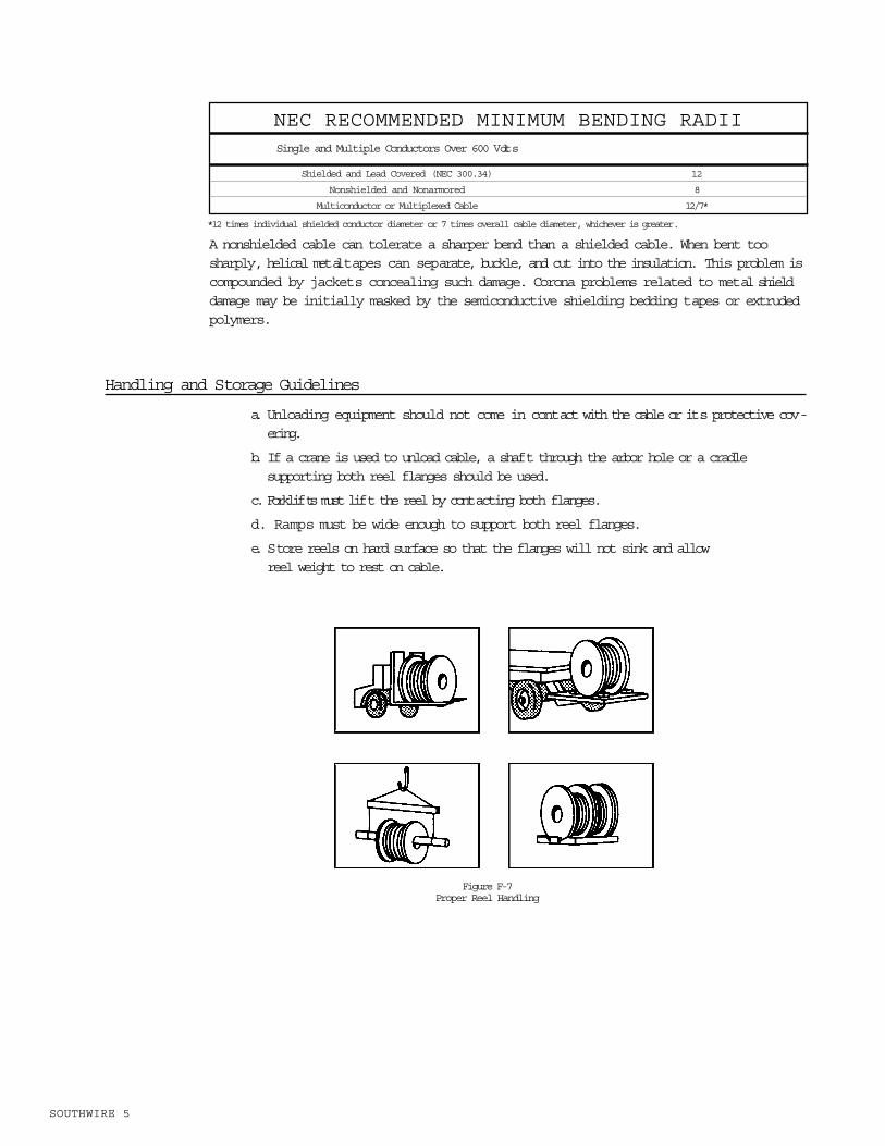
Handling and Storage Guidelines
a. Unloading equipment should not come in contact with the cable or its protective cov-ering.
b. If a crane is used to unload cable, a shaft through the arbor hole or a cradle supporting both reel flanges should be used.
c. Forklifts must lift the reel by contacting both flanges.
d. Ramps must be wide enough to support both reel flanges.
e. Store reels on hard surface so that the flanges will not sink and allow reel weight to rest on cable.
SOUTHWIRE 5
Single and Multiple Conductors Over 600 Volts
NEC RECOMMENDED MINIMUM BENDING RADII
Shielded and Lead Covered (NEC 300.34) 12
Nonshielded and Nonarmored 8
Multiconductor or Multiplexed Cable 12/7*
*12 times individual shielded conductor diameter or 7 times overall cable diameter, whichever is greater.
Figure F-7Proper Reel Handling

SOUTHWIRE 6
POWER CABLE INSTALLATION GUIDE
f. Reels should be stored out of harm s way. Consider both physical and environmental hazards.
g. Cable ends must always be sealed to prevent the entrance of moisture, etc.
h. Remove temporary cable lashing.
i. While pulling, in order to eliminate sharp bend and crossovers, always have a person feed the cable(s) straight into the conduit by hand or, for larger cables, over a large diameter sheave.
Figure F-9Feed Into Conduit
j. Do not pull cable directly across short, sharp angles. After pulling completely out ofone side of the enclosure, feed cable into the other side of the enclosure and pullthat segment.
*Caution: Minimum bending radii must be maintained.
Figure F-10Pull-Through Enclosure
Figure F-8Improper Reel Handling

Dynamometer Corrections
The dynamometer reading (R) is dependent upon the angle of pulling line ( ) from the cableto the dynamometer idler and then to the pulling mechanism; therefore, a correction to thedynamometer reading may be required to obtain the actual pulling tension (T).
Figure F-11Variables for Dynamometer Correction Equation
(E-1)
where: R = dynamometer reading, in pounds
= angle between pulling line, in degrees
W = tare weight of idler pulley assembly, in pounds
Example:
What is the actual pulling tension of a cable pull where the dynamometer reading is 5000pounds, the angle of the pulling line is 45, and the tare weight of the idler assembly is 15pounds? Using (E-1):
SOUTHWIRE 7

SOUTHWIRE 8
POWER CABLE INSTALLATION GUIDE
Diameters of Nonjacketed Cable Assemblies
The overall diameters of the cables in a multiple conductor assembly are used indetermining the circumscribed diameter of that assembly
DA= d Factor (E-2)
where: DA = circumscribed diameter of assembly
d = diameter of one cable of assembly
Factor = for the following list
Pull Boxes
To estimate the size of a pull box, take the greater of:
For Straight Pulls
For Angle or U Pulls
Figure F-12Pull Box Dimensions
1 1.000
2 2.000
3 2.155
4 2.414
5 2.700
6 3.000
7 3.000
8 3.310
9 3.610
Number of Cables Factor

where: L = minimum box length, in inches
Lo = minimum distance between cable entry and exit on thethe opposite side of the box, in inches
LA = minimum distance between the cable entry and the exit of the adjacent walls of the box, in inches
Ds = diameter of the largest shielded cable, in inches
DN = diameter of the largest nonshielded cables, in inches
D1, D2... = diameters of the remaining cable entering through the same wall of the box, in inches
For more information on sizing of pull and junction boxes, refer to the NEC Article 314.Information on spacing of conductors at pull and junction boxes is presented in Table 3.
TABLE 3
Cable Lubrication Selection
1. Reducing the coefficient of friction is the primary factor in the selection ofa lubricant.
2. Compatibility of the lubricant with cable and conduit is extremely important. The lubricant should not have any deleterious effects on the conduit or on the physical or electrical properties of the cable insulation, semiconducting, or jacketmaterials.
3. The lubricant and its residue should not propagate flame.
4. The lubricant should be UL or CSA listed.
5. The lubricant should contain no waxes or greases.
SOUTHWIRE 9
Size 1/2 3/4 1 1 1/4 1 1/2 2 2 1/2 3 3 1/2 4 5 6
CENTER-TO-CENTER SPACING
CONDUIT SPACING (INCHES)
1/2 1.38
3/4 1.50 1.62
1 1.75 1.88 2.00
1 1/4 2.00 2.12 2.25 2.50
1 1/2 2.12 2.25 2.38 2.62 2.75
2 2.38 2.50 2.75 3.00 3.12 3.38
2 1/2 2.62 2.75 3.00 3.25 3.38 3.00 4.00
3 3.00 3.12 3.38 3.62 3.75 4.00 4.38 4.75
3 1/2 3.38 3.50 3.62 3.88 4.00 4.38 4.62 5.00 5.38
4 3.69 3.88 4.00 4.25 4.38 4.75 5.00 5.38 5.62 6.00
5 4.38 4.50 4.62 4.88 5.00 5.38 5.62 6.00 6.25 6.62 7.25
5 5.00 5.12 5.25 5.50 5.62 6.00 6.25 6.62 7.00 7.25 8.00 8.62

SOUTHWIRE 10
POWER CABLE INSTALLATION GUIDE
Use
The cable jacket and/or conduit walls should be completely lubricated. The lubricant shouldbe applied immediately before, and/or, during the pull. This quantity should be increased asneeded for difficult pulling situations.
An estimate of the quantity of required lubricant can be determined from.2
(E-3)
where: Q = quantity, in gallons
L = conduit length, in feet
D = outside diameter of cable or inside diameter of conduit, in inches
INSTALLATION IN CONDUIT
Calculations should be made to indicate whether the pull looks easy or impossible, making thedecision to pull an obvious choice. When a marginal situation is encountered, the entire pullshould be reviewed. This review may include more rigorous calculations or trial pulls. A final deci-sion should be made based on installation factors known to the end user and installer.
The sizes of the conduit are determined based on the calculations of the clearances,jamming, and fill. Pulling tensions may then be evaluated by determining the maximumtension based on the pulling device used and the maximum tension that can be applied tothe conductors. The lesser of these two values is the maximum allowable tension (Tm).
The pulling tension (T) required to pull the cable through the conduit is then calculated andcompared to the maximum allowable tension. If the pulling tension exceeds the allowabletension, then conditions should be changed to ensure a successful pull. After calculatingpulling tensions, sidewall pressures (SP) may be calculated.
For further study on this subject, AEIC Publication G5-90 and IEEE Standard 1185 presentadditional details.3
Allowable Tension on Pulling Device
Do not exceed the allowable tension stated by the manufacturer of the pulling eye or 10,000pounds, whichever is less. Traditional conservative practices limit the allowable tension of abasket grip to 1,000 pounds. Under specific conditions, this limit can be safely exceeded.
Maximum Tension on Cable Conductors
The conductors of the cable are generally the only members that can bear the pulling forceswithout damage. Do not use metallic shielding wires, tapes, braids or armor not designed forthe purpose in pulling tension calculations.
2Polywater, Technical Talk, volume 4.3 AEIC Publication no G5-90, Underground Extruded Power Cable Pulling, AEIC Task Group 28, 2nd edition, May 2001;and IEEE Standard 1185-1994, Guide for Installation Methods for Generating Station Cables.
Definitions for the following equations and examples:

Tc = tension on each conductor, in pounds
S = allowable stress from Table 1, in pounds/cmil
A = area of each conductor, in cmil
N = number of conductors
Tcable = maximum allowable tension in the cable in pounds
Tdevice = maximum allowable tension on device in pounds
Tm = maximum allowable tension is the lesser of Tdevice or Tcable in pounds
*3/4 hard aluminum is allowed for power cable. The 2005 NEC defines use of AA-8000 for solid (8, 10, and 12 AWG) and stranded (8 AWG through 1000 kcmil) conductors.
Single Conductors
(E-4)
SOUTHWIRE 11
TABLE 4MAXIMUM ALLOWABLE CONDUCTOR STRESS (S)
Cable Type Material Temper lb/cmil
All Copper Soft 0.008
Power Aluminum Hard 0.008
Power Aluminum 3/4 Hard 0.006
Power Aluminum AA-8000* 0.006
U R D Aluminum 1/2 Hard 0.003
Solid Aluminum Soft 0.002
TABLE 5CONDUCTOR AREA
Size Cross-Sectional Area
AWG or kcmil cmil inches2 m m2
14 4110 0.00323 2.082
12 6530 0.00513 3.308
10 10,380 0.00816 5.261
8 16,510 0.01297 8.368
7 20,820 0.01635 10.55
6 26,240 0.02061 13.30
5 33,090 0.02599 16.77
4 41,740 0.03278 21.15
3 52,620 0.04133 26.66
2 66,360 0.05212 33.63
1 83,690 0.06573 42.41
1/0 105,600 0.08291 53.49
2/0 133,100 0.1045 67.42
3/0 167,800 0.1318 85.03
4/0 211,600 0.1662 107.2
250 250,000 0.1963 126.6
300 300,000 0.2356 152.0
350 350,000 0.2749 177.4
400 400,000 0.3142 202.7
450 450,000 0.3534 228.0
500 500,000 0.3927 253.4
550 550,000 0.4320 278.7
600 600,000 0.4712 304.0
650 650,000 0.5105 329.4
700 700,000 0.5498 354.7
750 750,000 0.5890 380.0
800 800,000 0.6283 405.4
900 900,000 0.7069 456.1
1000 1,000,000 0.7854 506.7

SOUTHWIRE 12
POWER CABLE INSTALLATION GUIDE
Example:
Power Cable, single conductor, 4/0 AWG aluminum, hard
Multiple ConductorsMultiple conductors in parallel, or multiplexed, and multiple conductor cables.
Three or fewer conductors
(E-5)
Example 1: Power cable, two single conductor, 4/0 AWG aluminum, hard
Example 2: Power Cable, three-conductor, 4/0 AWG aluminum, hard
More than three conductors
(E-6)
Example 3: Control Cable, four conductor, 6 AWG copper
Using equation (E-4):
Using equation (E-6)
CAUTION:
Pulling different conductor sizes at the same time is not recommended if the conductor sizeorother cable characteristics are significantly different.
If you must pull different size conductors, it must be done with care. For example, if a runrequires three 350 kcmil and three 8 AWG single conductor cables, it would bepreferable,though not necessarily ideal, to pull the three 350 kcmil single conduct cables andone three conductor 8 AWG multiple conductor cable at the same time.
Pulling additional cables into an existing conduit system is generally not recommended. Ifthis must be done, extreme caution must be taken. Of special concern is the cutting actionof the tensioned pulling rope.

Equations for Pulling Tension
The following equations are used to calculate pulling tension. They include the following variables:
Tin = tension into a section in pounds
Tout= tension out of a section in pounds
w = weight correction factor, dimensionless
m = coefficient of dynamic friction, dimensionless
W = total cable assembly weight on pounds/foot
L = straight section length in feet
U = straight section angle from horizontal in radians
f = bend section angle in radians
R = bend section radius in feet
e = 2.71 natural logarithm base
Horizontal Straight Section
(E-7)
Inclined and Vertical Straight Section
Pulling Up a Straight Section
(E-8)
Pulling Down a Straight Section
(E-9)
Horizontal Bend Section
(E-10)
Vertical Concave Up Bend
Pulling Up Through a Bend
(E-11)
Pulling Down Through a Bend
(E-12)
Vertical Concave Down Bend
Pulling Up Through a Bend
(E-13)
Pulling Down Through a Bend
(E-14)
SOUTHWIRE 13

SOUTHWIRE 14
POWER CABLE INSTALLATION GUIDE
Commonly Used Approximation for BendsIt is common practice to use the following approximation in lieu of bend equations E-10, E-11, E-12, E-13, and E-14
(E-15)
Coefficient of Friction
The coefficient of dynamic friction (m ) is a measure of the friction between a moving cableand the conduit. The coefficient of friction can have a large impact on the tension calculation.It can vary from 0.1 to 1.0 with lubrication and can exceed 1.0 for unlubricated pulls. Typicalvalues for the coefficient of friction are presented in Table 6. Pulls should never be stoppedand restarted because the coefficient of static friction will always be higher than the coeffi-cient of dynamic friction.(A) These represent conservative values for use in lieu of more exact information.4
(B) Conduit Codes:M = metallic, steel or aluminumPVC= polyvinyl chloride, thin wall or heavy schedule 40FIB = fiber conduit Orangeburg or NocreteASB= asbestos cement Transite or Korduct
The coefficient of friction between a cable exterior (jacket/sheath) and conduit varies withthe type of jacket or sheath, type and condition of conduit, type and amount of pulling lubri-cant used, cable temperature, and ambient temperature. High ambient temperatures (80 Fand above) can increase the coefficient of dynamic friction for cable having a nonmetallicjacket.
Pulling lubricants must be compatible with cable components and be applied while the cable isbeing pulled. Pre-lubrication of the conduit is recommended by some lubricant manufacturers.
4 Gene C. Neetz, Coefficient of Friction Measurement Between Cable and Conduit Surfaces Under Varying Loads, in 1985IEEE Transactions on Power Apparatus and Systems, vol. PAS-104, no. 1, pp. 16-21.
TABLE 6
Type of Conduit (B)
Cable Exterior M PVC FIB ASB
PVC- Polyvinyl Chloride 0.4 0.35 0.5 0.5
PE- Low Density HMW 0.35 0.35 0.5 0.5Polyethylene
PO- SOLONON 0.35 0.35 0.5 0.5(Polyolefin)
CSPE- Hypalonfi 0.5 0.5 0.7 0.6(Chlorosulfonated Polyethylene)
XLPE- Cross-Linked PE 0.35 0.35 0.5 0.5
Nylon 0.4 0.35 0.5 0.5
CPE- Chlorinated PE 0.5 0.5 0.7 0.6
TYPICAL COEFFICIENTS OF DYNAMIC FRICTION (m )ADEQUATE CABLE LUBRICATION DURING PULL (A)

Configuration
The configuration of three single-conductor cables in a conduit is determined by the ratio ofthe conduit inner diameter (D) to the outer diameter (d) of one of the single cables (D/d ratio).
Figure F-13Configuration of Three Single Conductors
A cradled configuration develops when three single-conductor cables are pulled into a conduitwhere the D/d ratio is 2.5 or greater. A triangular configuration develops when three singleconductor cables are pulled into a conduit where the D/d ratio is less than 2.5. These cablesmay be pulled from individual reels, tandem reels, or a single reel with parallel wound cables.
W eight Correction Factor
The configuration of cables can affect cable tension. A weight correction factor (w) is used inthe tension equations to account for this effect. The value for the weight correction factor isdetermined from the equations that follow:
1 cable (single)
(E-16)
3 cables (triangular)
(E-17)
3 cables (cradles)
(E-18)
4 cables or more (complex)
(E-19)
where: w = weight correction factor
D = inner diameter of conduit
d = outside diameter of the cable
Note: When pulling dual cables, use the conservative three-cable (triangular) factor.
Figure F-14Cable Configurations
SOUTHWIRE 15
SOUTHWIRE 16
POWER CABLE INSTALLATION GUIDE
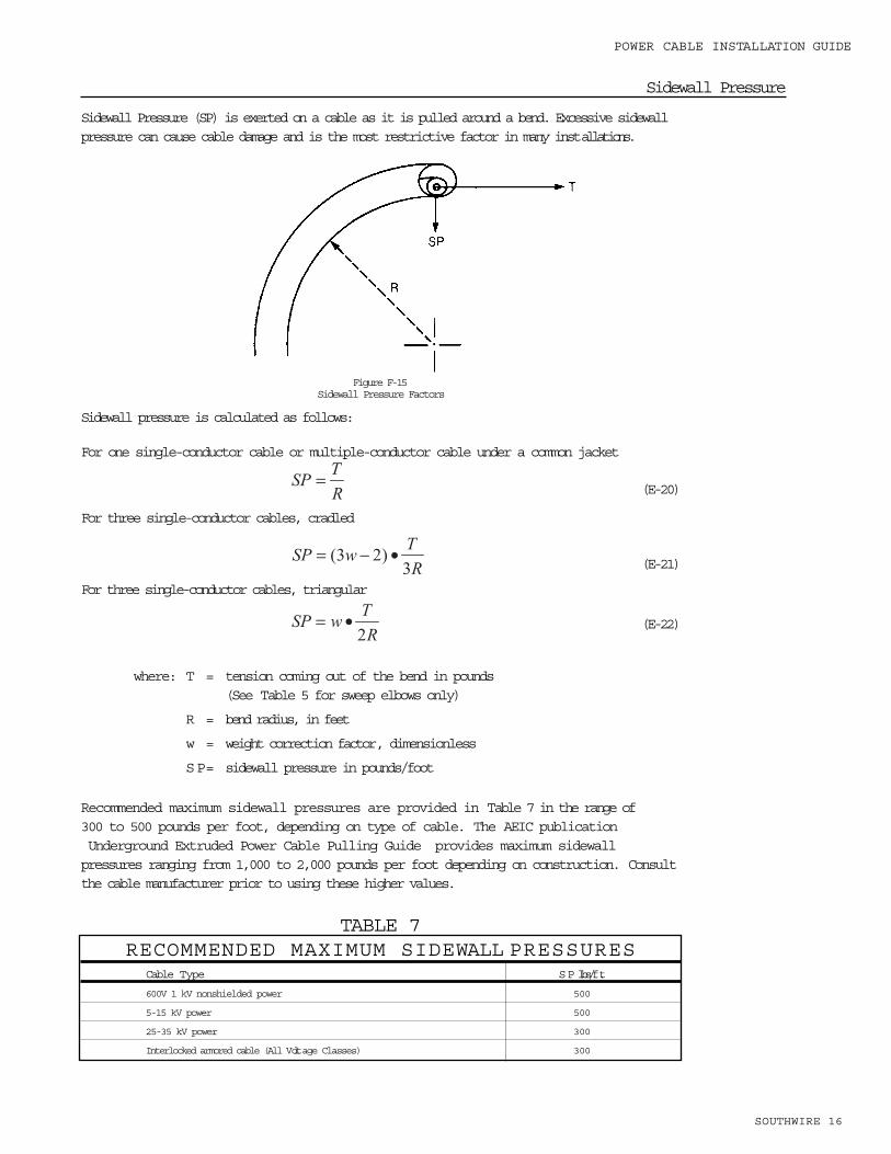
Sidewall Pressure
Sidewall Pressure (SP) is exerted on a cable as it is pulled around a bend. Excessive sidewallpressure can cause cable damage and is the most restrictive factor in many installations.
Figure F-15 Sidewall Pressure Factors
Sidewall pressure is calculated as follows:
For one single-conductor cable or multiple-conductor cable under a common jacket
(E-20)
For three single-conductor cables, cradled
(E-21)
For three single-conductor cables, triangular
(E-22)
where: T = tension coming out of the bend in pounds(See Table 5 for sweep elbows only)
R = bend radius, in feet
w = weight correction factor, dimensionless
SP= sidewall pressure in pounds/foot
Recommended maximum sidewall pressures are provided in Table 7 in the range of300 to 500 pounds per foot, depending on type of cable. The AEIC publicationUnderground Extruded Power Cable Pulling Guide provides maximum sidewall pressures ranging from 1,000 to 2,000 pounds per foot depending on construction. Consultthe cable manufacturer prior to using these higher values.
R
TSP =
TABLE 7RECOMMENDED MAXIMUM SIDEWALL PRESSURES
Cable Type SP lbs/ft.
600V 1 kV nonshielded power 500
5-15 kV power 500
25-35 kV power 300
Interlocked armored cable (All Voltage Classes) 300
Clearance
Clearance is the distance between the top of the uppermost cable in the conduit and theinner top surface of the conduit. It should be at least 10% of the conduit inner diameter orone inch for large cables or installations involving numerous bends.
Equations for calculating clearance (CL) are presented as follows:
For single cable
(E-23)
For three cables, triplexed, triangular
(E-24)
For three cables, cradles
(E-25)
where: D = conduit inner diameter, in inches
d = cable outer diameter, in inches
When calculating clearance, ensure all cable diameters are equal. If in doubt, use thetriplexed configuration equation. The cables may be single or multiple-conductorconstruction.
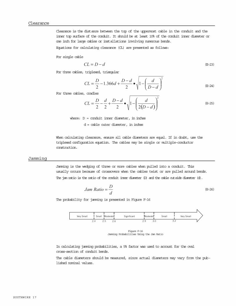
Jamming
Jamming is the wedging of three or more cables when pulled into a conduit. This usually occurs because of crossovers when the cables twist or are pulled around bends.
The jam ratio is the ratio of the conduit inner diameter (D) and the cable outside diameter (d).
(E-26)
The probability for jamming is presented in Figure F-16
Figure F-16Jamming Probabilities Using the Jam Ratio
In calculating jamming probabilities, a 5% factor was used to account for the oval cross-section of conduit bends.
The cable diameters should be measured, since actual diameters may vary from the pub-lished nominal values.
SOUTHWIRE 17
Very Small Small Moderate Significant Moderate Small Very Small
3.23.02.92.62.52.4

SOUTHWIRE 18
POWER CABLE INSTALLATION GUIDE
Conduit Fill
Conduit fill is the percentage of the area inside the conduit taken up by the cable(s). Consultapplicable codes, industry standards, and manufacturers data for furtherinformation on fill. Dimensions and percent area of conduit and tubing are provided in Table8. Dimensions for additional types of conduits can be found in Chapter 9 of the 2005National Electrical Code.
(E-27)
where: d = outside diameter of the cable in inches
D = inside diameter of the conduit in inches
N = number of cables
TABLE 8DIMENSIONS AND PERCENT AREA CONDUIT AND TUBING
Trade Size Internal Diameter Total Area 2 Wires Over 2 Wires 1 Wire
Inches Inches m m 100% Sq. In. 31% Sq. In. 40% Sq. In. 53% Sq. In.
1/2 0.602 15.3 0.285 0.088 0.114 0.151
3/4 0.804 20.4 0.508 0.157 0.203 0.269
1 1.029 26.1 0.832 0.258 0.333 0.441
1 1/4 1.360 34.5 1.453 0.450 0.581 0.770
1 1/2 1.590 40.4 1.986 0.616 0794 1.052
2 2.047 51.99 3.291 1.020 1.316 1.744
2 1/2 2.445 62.10 4.695 1.455 1.878 2.488
3 3.042 11.27 7.268 2.253 2.907 3.852
3 1/2 3.521 89.43 9.737 3.018 3.895 5.161
4 3.998 101.5 12.554 3.892 5.022 6.654
5 5.016 127.4 19.761 6.126 7.904 10.473
6 6.031 153.2 28.567 8.856 11.427 15.141
RIGID PVC CONDUIT SCHEDULE 40 AND HDPE CONDUIT
Trade Size Internal Diameter Total Area 2 Wires Over 2 Wires 1 Wire
Inches m m Inches m m 100% Sq. In. 31% Sq. In. 40% Sq. In. 53% Sq. In.
1/2 16 0.622 15.8 0.304 0.094 0.122 0.161
3/4 21 0.824 20.9 0.533 0.165 0.213 0.283
1 27 1.049 26.6 0.864 0.268 0.346 0.458
1 1/4 35 1.380 35.1 1.496 0.464 0.598 0.793
1 1/2 41 1.610 40.9 2.036 0.631 0.814 1.079
2 53 2.067 52.5 3.356 1.040 1.342 1.778
2 1/2 63 2.731 69.4 5.858 1.816 2.343 3.105
3 78 3.356 85.24 8.846 2.742 3.538 4.688
3 1/2 91 3.834 97.38 11.545 3.579 4.618 6.119
4 103 4.334 110.1 14.753 4.573 5.901 7.819
ELECTRICAL METALLIC TUBING (EMT)

Calculation Procedure
The following is a recommended procedure for calculating installation parameters for cablesin conduit:
a. Select conduit size based on required fill, clearance, jamming, and applicable codes and standards.
b. Select values for conduit type, bend radii, and coefficient of friction. Table 9 lists the inside radius for
manufactured rigid steel conduit sweep elbows.
c. Determine cable weight (W) from manufacturers data sheets.
d. Calculate weight correction factor (w).
e. Calculate maximum allowable tension.
f. Calculate pulling tension (T) and sidewall pressure (SP) for each segment.
g. Compare calculated results to established limits.
h. If limits are exceeded, consider one or more of the following:
1) Increase bend radii
2) Decrease fill
3) Reduce number of bends
4) Reverse pull
5) Pull in stages
6) Decrease length of pull
SOUTHWIRE 19
Trade Size Internal Diameter Total Area 2 Wires Over 2 Wires 1 Wire
Inches Inches m m 100% Sq. In. 31% Sq. In. 40% Sq. In. 53% Sq. In.
3/8 0.384 9.75 0.116 0.036 0.046 0.061
1/2 0.635 16.1 0.317 0.098 0.127 0.168
3/4 0.824 20.9 0.533 0.165 0.213 0.282
1 1.020 25.91 0.817 0.256 0.327 0.433
1 1/4 1.275 32.39 1.277 0.396 0.511 0.677
1 1/2 1.538 39.07 1.857 0.576 0.743 0.984
2 2.040 51.82 3.269 10.13 1.307 1.732
2 1/2 2.500 63.50 4.909 1.522 1.964 2.602
3 3.000 76.20 7.069 2.191 2.827 3.746
3 1/2 3.500 88.90 9.621 2.983 3.848 5.099
4 4.000 101.6 12.566 3.896 5.027 6.660
FLEXIBLE METAL CONDUIT
Trade Size Internal Diameter Total Area 2 Wires Over 2 Wires 1 Wire
Inches Inches m m 100% Sq. In. 31% Sq. In. 40% Sq. In. 53% Sq. In.
1/2 0.526 13.4 0.217 0.067 0.087 0.115
3/4 0.722 18.3 0.409 0.127 0.164 0.217
1 0.936 23.8 0.688 0.213 0.275 0.365
1 1/4 1.255 31.88 1.237 0.383 0.495 0.656
1 1/2 1.476 37.49 1.711 0.530 0.684 0.907
2 1.913 48.59 2.874 0.891 1.150 1.152
2 1/2 2.290 58.71 4.119 1.277 1.647 2.183
3 2.864 72.75 6.442 1.997 2.577 3.414
3 1/2 3.326 84.48 8.688 2.693 3.475 4.605
4 3.786 96.16 11.258 3.490 4.503 5.967
5 4.768 121.1 17.855 5.535 7.142 9.463
6 5.709 145.0 25.598 7.935 10.239 13.567
RIGID PVC CONDUIT, SCHEDULE 80
TABLE 8 (CONTINUED)

SOUTHWIRE 20
POWER CABLE INSTALLATION GUIDE
INSTALLATION IN CABLE TRAY
When pulling cable into cable trays the same approach should be used for cable installedinto conduit. Care must be given to the run lengths, number of cable turns, and cablesheave size to ensure the cable s maximum pulling tension, minimum bending radius, andmaximum allowable sidewall pressure are not exceeded, subjecting the cable to possibledamage.
Rollers and Sheaves
When pulling around bends in cable tray, excessive sidewall pressure can damage thecable. Sidewall pressure can be reduced by using a large radius sheave. Many times, alarge radius sheave cannot be used and an assembly of multiple smaller sheaves is used.Care should be given to prevent damage due to high sidewall pressure on the individualsheaves. The individual sheaves should have a minimum inside radius of 1.25 inches withat least one sheave per 20 of the bend. A three-sheave assembly for a 90 bend shouldnever be used.
Rollers and sheaves must be well-maintained and lubricated to achieve the lowest possiblecoefficient of friction.
Roller Mounting
Rollers must be properly spaced to prevent the cable from touching the tray.
Rollers must be free-turning.
When the tray changes direction, vertically or horizontally, sheave radii must be large enoughto meet the minimum bending and maximum allowable sidewall pressure limits.
Elbow Centerline Radius (inches)
12 15 18 24 30 36 42 48
Conduit Size Elbow Centerline Radius (feet)
1 0.96 1.21 1.46 1.96 2.46 2.96 3.46 3.96
1 1/4 0.94 1.19 1.44 1.94 2.44 2.94 3.44 3.94
1 1/2 0.93 1.18 1.43 1.93 2.43 2.93 3.43 3.93
2 0.91 1.16 1.41 1.91 2.41 2.91 3.41 3.91
2 1/2 1.15 1.40 1.90 2.40 2.90 3.40 3.90
3 1.37 1.87 2.37 2.87 3.37 3.87
3 1/2 1.35 1.85 2.35 2.85 3.35 3.85
4 1.83 2.33 2.83 3.33 3.83
5 2.29 2.79 3.29 3.79
6 2.75 3.25 3.75
SWEEP ELBOW RADIUS
TABLE 9

Roller Spacing
Roller spacing will vary with:
Cable weight
Cable tension
Cable construction
Roller height above the tray
To estimate roller spacing, the following equation can be used:
(E-28)
where: s = distance between rollers, in feet
h = height of top roller above the tray bottom, in feet
T = tension, in pounds
w = weight of cable, per foot
The distance will be conservative for armored cable because the equation assumes a per-fectly flexible cable. When possible, a length of cable should be used to determine maxi-mum spacing under no tension, as a check for the calculated values.
Pulling Tensions
Calculations of pulling tensions for cable trays are similar to those for pulling cable in con-duit, adjusting the coefficient of friction to reflect using rollers and sheaves.
Horizontal Straight Sections
The tension for a horizontal straight section of cable tray can be estimated with the followingequation:
Tout= (E-29)
where: Tout= tension out of a section, in pounds
= coefficient of dynamic friction ( = 0.15)
W = total cable assembly weight, in pounds/foot
L = straight section length, in feet
Tin= tension into a section, in pounds
The coefficient of friction ( ) equal to 0.15 accounts for the low-rolling friction of well-main-tained rollers.
SOUTHWIRE 21
Inclined Straight Sections
Use the following equation for pulling up an inclined straight section:
Tout = (E-30)
Use the following equation for pulling down an inclined straight section:
Tout = (E-31)
where: Tout= tension out of a section, in pounds
W = total cable assembly weight, in pounds/foot
= straight section angle from horizontal, in radians
L = straight section length, in feet
= coefficient of dynamic friction ( = 0.15)
Tin = tension into a section, in pounds
Vertical Sections
When pulling straight up or down, the equation for inclined pulls simplifies to the followingequations:
Pulling Straight Up
(E-32)
Pulling Straight Down
(E-33)
where: W = total cable assembly weight, in pounds/foot
L = straight vertical section length, in feet
Tension in Bends
If the sheaves in the bends in cable trays are well-maintained, they will not have the multi-plying effect on tension that bends in conduit have. The sheaves will turn with the cable,allowing the coefficient of friction to be assumed zero. This results in the commonly-usedapproximation for conduit bend equation , becoming one. Even though cable tray bendsproduce no multiplying effect, it is essential for heavier cables to include the force requiredto bend the cable around the sheave. A 200-pound adder per bend should be used for athree-conductor 500 kcmil copper conductor armored cable. If the sheaves are not well-maintained, the bend will have a multiplying effect. The tension in the pull must then be cal-culated using the same equations used for installations in conduit.
Tension Entering Cable Tray
Because the tension entering the cable tray is rarely zero, it is critical that the tensionrequired to remove the cable from the reel be used to calculate the total tension for theinstallation.
Many times it is difficult to know the location of the reel of cable until the cable is being
SOUTHWIRE 22

installed. The following equations are used to approximate the tension entering the cable
tray and can be used to determine how critical the reel position will be for the cable pull.
Feeding Off Reel Horizontally
When the cable reel can be elevated so that the cable can be pulled directly into the tray,the following equation should be used to approximate the tension required to remove thecable from the reel:
Treel= 25W pound (E-34)
where: Treel= tension, in pounds
W = total cable assembly weight, in pounds/foot
Feeding Off Reel Vertically
When the cable reel must be positioned directly below the cable tray the following equationshould be used to approximate the tension required to pull the cable into the tray.
T = W L pounds (E-35)
where: W = total cable assembly weight, in pounds/foot
L = straight vertical section length, in feet
The tension can now be approximated for pulling the cable into the tray from a horizontal position when the reel is placed directly under the tray. To estimate the tension entering the cable tray when the reel must be placed away from and below theentrance to the tray, use the equation for feeding off the reel vertically where the height(L) is the vertical distance between the reel and cable tray. To allow for bending forces asthe cable comes off the reel, the minimum tension added should be 25W.
TYPICAL CALCULATION FOR CABLES IN CONDUIT
Example:
Three THHN single-conductor 4/0 AWG copper
Single-conductor diameter (d) = 0.626 inches
Cable weight (W) = 3x 0.711 lbs/ft = 2.13 lbs/ft
Pulling device (Tdevice) = 10,000 pound eye
EMT conduit, trade size 2 inch
Bends 1-2, 3-4, and 5-6 are 90 (1.57 radians)
Use 36-inch sweep elbows (inside radius 2.91 feet)
Figure F-17Conduit Layout
1. Select conduit size based on required fill, clearance, jamming, and applicable codes and standards.
SOUTHWIRE 23
100’
3
4
50’5.6.7
S
Pull
400’ 1
5
6
7
100’
Elevation View
2

SOUTHWIRE 24
POWER CABLE INSTALLATION GUIDE
a) EMT trade size 2 inch: D = 2.067 inches from Table 8
b) Conduit fill, using equation (E-27):
W ithin limits, if we assume 40% fill as the maximum specification requirements.
c) Configuration, jamming, clearance
First determine configuration (See Figure F-13)
Because:
Configuration will be cradled.
Jamming can now be evaluated using equation (E-26)
Jamming is acceptable because the probability for jamming is very small since:
Clearance can be determined using equation (E-25)
Clearance is acceptable because clearance is significantly greater than 10% of theconduit inside diameter, and is also greater than 1 inch.
2. Select values for conduit type, bend radii, and coefficient of friction
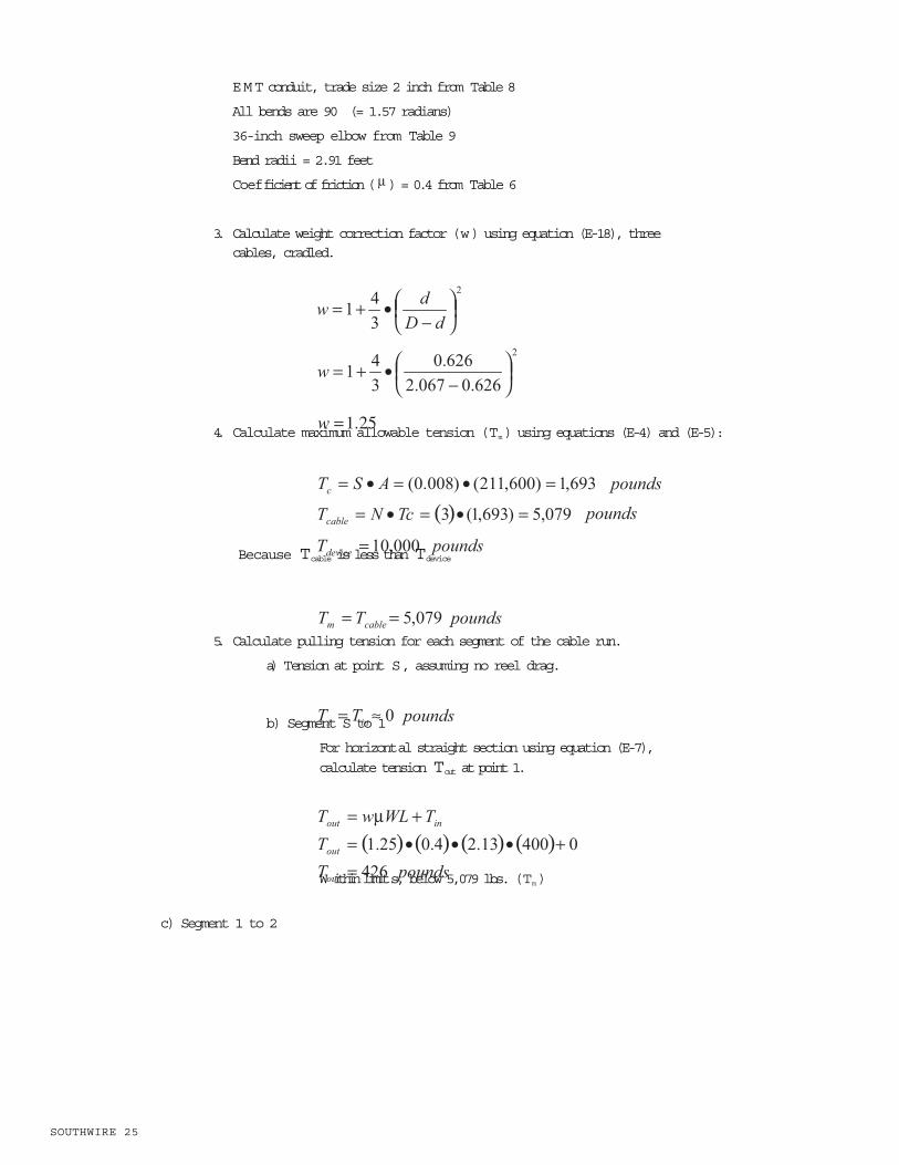
EMT conduit, trade size 2 inch from Table 8
All bends are 90 (= 1.57 radians)
36-inch sweep elbow from Table 9
Bend radii = 2.91 feet
Coefficient of friction ( ) = 0.4 from Table 6
3. Calculate weight correction factor (w) using equation (E-18), three cables, cradled.
4. Calculate maximum allowable tension (Tm) using equations (E-4) and (E-5):
Because Tcable is less than Tdevice
5. Calculate pulling tension for each segment of the cable run.
a) Tension at point S, assuming no reel drag.
b) Segment S to 1
For horizontal straight section using equation (E-7),
calculate tension Tout at point 1.
W ithin limits, below 5,079 lbs. (Tm)
c) Segment 1 to 2
SOUTHWIRE 25

SOUTHWIRE 26
POWER CABLE INSTALLATION GUIDE
For horizontal bend section using approximate equation (E-18),
calculate tension Tout at point 2.
W ithin limits, below 5,079 lbs. (Tm)
d) Segment 2 to 3
For horizontal straight section using equation (E-7),
calculate tension Tout at point 3.
W ithin limits, below 5,079 lbs. (Tm)
e) Segment 3 to 4
For horizontal bend section using approximate equation (E-15),
calculate tension Tout at point 4.
W ithin limits, below 5,079 lbs. (Tm)
f) Segment 4 to 5
For horizontal straight section using equation (E-7),
calculate tension Tout at point 5.
W ithin limits, below 5,079 lbs. (Tm)
g) Segment 5 to 6
Vertical concave downbend using approximate equation (E-15),
calculate tension Tout at point 6.
CAUTION:
Probably acceptable even through slightly above 5,079 lbs. (Tm)
h) Segment 6 to 7
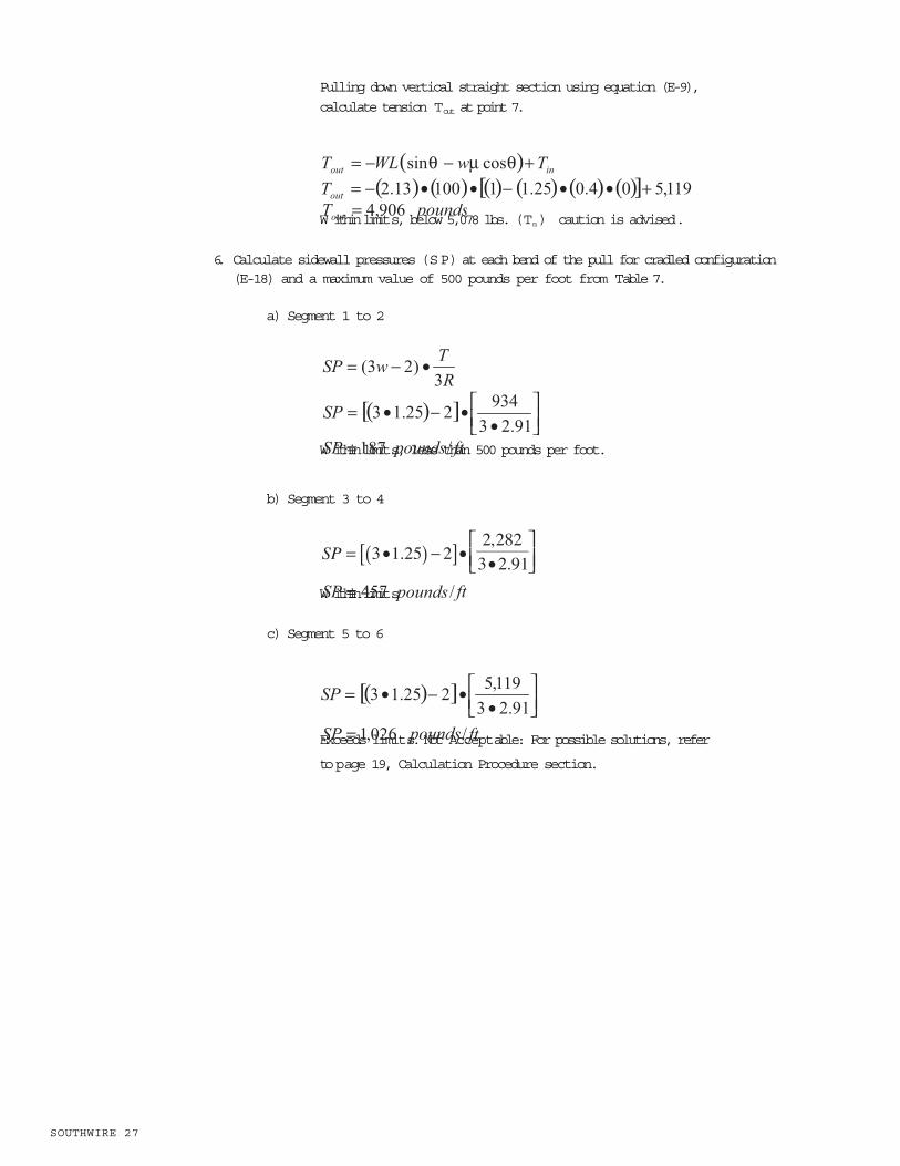
Pulling down vertical straight section using equation (E-9),
calculate tension Tout at point 7.
W ithin limits, below 5,078 lbs. (Tm) caution is advised.
6. Calculate sidewall pressures (SP) at each bend of the pull for cradled configuration(E-18) and a maximum value of 500 pounds per foot from Table 7.
a) Segment 1 to 2
W ithin limits, less than 500 pounds per foot.
b) Segment 3 to 4
W ithin limits.
c) Segment 5 to 6
Exceeds limits. Not Acceptable: For possible solutions, refer
to page 19, Calculation Procedure section.
SOUTHWIRE 27

SOUTHWIRE 28
POWER CABLE INSTALLATION GUIDE
CABLES BURIED DIRECTLY IN EARTH
The NEC, NESC, and IEEE provide basic information regarding direct burial of electricalcables.5
Depth of Burial
1. The depth of burial shall be sufficient to protect the cable from damage imposed by expected surface usage.
2. Burial depths as indicated in Table 6 are considered adequate for supply cables or conductors, except as noted in a, b, or c.
Figure F-18Typical Burial Cross-Section
EXCEPTION: Street light cables operating at not more than 150 V to ground may be buried at a depth not less
than 18 in. (450mm).
a. In area where frost conditions could damage cables, burial depths should be greater.b. Lesser depths may be used where supplemental protection is provided. The supplemental protection shouldbe sufficient to protect the cable from damage imposed by expected surface usage.
c. Where the surface is not to final grade, the cable should be placed to meet or exceed the requirements indicat-ed above, both at the time of installation and when the surface is to final grade.
Trenching
The bottom of the trench should be smooth, undisturbed, well-tamped earth or sand. When excavation is in rock or rocky soils, the cable should be laid on a protective layer ofwell-tamped backfill. Backfill within 4 inches of the cable should be free of materials thatmay damage the cable. Backfill should be adequately compacted. Machine compactionshould not be used within 6 inches of the cable.
A protective covering above the cable will warn excavators of the presence of an underlying cable.
5 NEC, section 300.5; National Electrical Safety Code (NESC), 2002 edition, section 35; ANSI C2-2002, Secretariat IEEE.
TABLE 10
NESC TABLE 352-1SUPPLY CABLE OR CONDUCTOR BURIAL DEPTHVoltage Depth of BurialPhase to Phase (in.) (mm)
0 to 600 24 600
601 to 50,000 30 750
50,001 and above 42 1070
6“ to 8”
3“ to 4”
Compacted Backfill
Optional Protective Cover
Tamped Sand orStone-Free Earth
Tamped Soft Bedding of Sandor Stone-Free Earth

Plowing
Plowing of cable should not result in damage to the cable from rocks or other solid materi-als. The design of cable plowing equipment and the plowing of cable should not damagethe cable by exceeding bend, sidewall pressure, cable tension, or other allowable limits.
Supplemental Information
A jacketed multiconductor is preferable to the installation of single-conductor cables to easeinstallation and avoid crossovers.
Under vehicular and pedestrian traffic ways, it is good practice to pull cable through a conduit.
AERIAL INSTALLATION
Sag and Tension
This information is intended for initial design information only. The cable manufacturer cansupply detailed data, which include thermal expansion and creep. These factors increase thearc length after initial stringing, resulting in an increased sag.
The calculation for sag and tension is based on the equation for parabolas. This equationclosely approximates a catenary curve for small deflections, as given by:
(E-36)
where: TH = horizontal tension in conductor or messenger, in pounds
s = length of span between supports, in feet
w = weight of cable assembly, includes supporting conductor/messenger, saddles, lashings, etc., in pounds per foot
d = sag, in feet
The total messenger tension, at its support, consists of a horizontal and a verticalcomponent. The vertical component has been neglected.
The tension shall not exceed:
a) 50% of rated breaking strength of the messenger under the assumed ice andwind loading
b) 25% of rated breaking strength for final unloaded tension at 60 F (15 C)
SOUTHWIRE 29

SOUTHWIRE 30
POWER CABLE INSTALLATION GUIDE
Ice and Wind Loading
Ice and wind loading on aboveground cables and conductors are determined by location.The NESC divides the United States into three loading districts Light, Medium, and Heavy.
The weight of the ice, force of the wind, and resultant weight of the cable can be calculatedby the following equations.6
(E-37)
(E-38)
(E-39)
where: i = weight of ice, in pounds per foot
t = thickness of ice, in inches
D = outside diameter of cable, in inches
h = force of wind, in pounds per foot
P = horizontal wind pressure, in pounds per square foot
W L= resultant weight of loaded cable, in pounds per foot
W = weight of cable only (i.e. without ice), in pounds per foot
K = constant from NESC Table 251-1
Values of t, P, and K are presented in Table 11. This information is extracted from Tables 250-1 and 251-1 of the NESC.
Figure F-19NESC Loading District Boundaries
6 Archer E. Knowlton, ed. Standard Handbook for Electrical Engineers, 8th edition (McGraw-Hill, 1949).

TABLE 11
*Figure F-19 presents Loading District boundaries.** For horizontal wind velocity of 70 mph and above, refer to NESC Table 250-2.
Additional Information
Additional information can be found in ICEA Publication P-79-561 Guide for Selecting AerialCable Messengers and Lashing Wires. 7
Typical breaking strengths of messengers are presented in the following table:
TABLE 12
CABLES UNDER VERTICAL TENSION
ICEA Support Requirements
ICEA suggests that for supported vertical installations, such as vertical shafts or risers andbore holes, the supporting member may be the conductor(s) or the armor wires in wirearmored cables.8 Strength requirements are expressed in terms of a minimum safety factor(Fs), which is the ratio of rated cable strength to supported cable weight. The equation is:
(E-40)
where: Fs = safety factor, per Table 9
N = number of conductors
A = cross-sectional area of one conductor or one armor wire, in square inches
T = tensile stress allowed on supporting member from Table 10, in psi
W = weight of cable, in pounds/foot
= length of cable, in feet
7ICEA P-79-561-1985, Guide for Selecting Aerial Cable Messengers and Lashing Wires.8 ICEA S-68-516, section 4.5, and IEEE Standard 635-1989, IEEE Guide for Selection and Design of Aluminum Sheaths for Power Cables.
TABLE 13SOUTHWIRE 31
Heavy Medium Light
LOADING DISTRICT VARIABLES
t, radial thickness of ice (in.) 0.50 0.25 0
**P, horizontal wind pressure (Pa) 4 4 9
K, a constant (lb/ft.) 0.30 0.20 0.05
Temperature ( F) 0 15 30
VariablesLoading District*
MESSENGER CHARACTERISTICSNominal
MessengerSize (inch)
Numberof
Strands
EHS Galvanized Steel
W eight (Lb/ft.) Breaking Strength (lbs.)
1/4 7 0.121 6,650
5/16 7 0.205 11,200
3/8 7 0.273 15,400
7/16 7 0.399 20,800
1/2 7 0.512 26,900
9/16 7 0.671 35,000
9/16 19 0.637 33,700

TABLE 14
Support can be achieved by cable clamps that will not damage cable components. The spacing (S) of clamps can be determined by using the following equation which results in an approximate value.
(E-41)
where: D = outer diameter of cable in inches
L = length of clamp along cable axis in inches
W = weight of cable in pounds/foot
NEC Support Requirements
The NEC defines support in vertical raceways one vertical support at the top, or as closeas practical, plus a support for each spacing interval as defined in Table 15.
TABLE 15
* Reprinted with permission from NFPA 70-2-5, the National Electric Codefi, Copyright 2005, National Fire Protection Association, Quincy, MA 02269. This reprinted material is not the complete and official position of the National FireProtection Association on the referenced subject which is represented only in the standard in its entirety.
FIELD REMOVAL OF MOISTURE FROM POWER CABLES
Normally, cable ends are sealed until the cable is installed to prevent moisture from enteringthe cable. When open cable ends are submerged or exposed, water can migrate inside the
SOUTHWIRE 32
POWER CABLE INSTALLATION GUIDE
NEC TABLE 300.19 (A) SPACING FOR CONDUCTO RSize of WireAWG orkcmil
Support ofConductors in
Vertical
Aluminum orCopper-CladAluminum
Copper
18 AWG through 8 AW G Not Greater Than 100 feet 100 feet
6 AWG through 1/0 AW G Not Greater Than 200 feet 100 feet
2/0 AWG through 4/0 AW G Not Greater Than 180 feet 80 feet
Over 4/0 AWG through 350 kcmil Not Greater Than 135 feet 60 feet
Over 350 kcmil through 500 kcmil Not Greater Than 120 feet 50 feet
Over 500 kcmil through 750 kcmil Not Greater Than 95 feet 40 feet
Over 750 kcmil Not Greater Than 85 feet 35 feet
Tensile Stress, (T)psi
MAXIMUM STRESS ALLOWED ON SUPPORTING MEMBERS
Annealed Copper 24,000
Medium Hard Copper 40,000
Aluminum 1350 17,000
Armor Wire, Galvanized Steel 50,000
Materials
Safety FactorFs
SAFETY FACTOR FOR CABLES UNDER VERTICAL TENSION
Unarmored 7
Armored Riser & Shaft 7
Armored Borehole 5
Cable Type
cable. If water remains in a medium-voltage cable, it can accelerate insulation deteriorationand lead to premature failure.
You can remove water from wet cable by purging the cable with dry nitrogen gas underpressure. Any wire or cable product that does not contain fillers and is suitable for wet loca-tions, can be purged under engineering supervision.
If you do have to purge a length of wire or cable, always test it before you energize it. At a minimum, conduct an insulation resistance test with a megohm-meter.
NOTE: The purging procedures described here assume the water in the wire or cable does not contain unusually high concentrations of oils or chemicals, such as may be foundin floodwaters. If you suspect that water inside a cable carries unusual contaminates, con-sult the manufacturer before deciding to continue using the wire or cable.
If you are not certain about the source of water in cable, water samples from the cable, thework site, and the manufacturer can be analyzed for mineral content. Comparing mineralcontents can, many times, identify the source of the water.
Required Materials
The medium for purging moisture from cable is dry nitrogen gas, available at most weldingsupply houses. You will need:
1. A cylinder of dry nitrogen gas with a dew point of 60 C.
2. A regulator to reduce the gas pressure to approximately 15 psi.
3. Some 1/4 gas hose and some hose clamps to run between the tank and the cable end.
4. A hose nipple to connect the hose to the regulator.
5. A cable cap that fits the cable end and a radiator hose clamp that fits the end cap.
6. An automobile tire valve stem assembly with no valve core installedto connect the hose to the cable cap.
7. Plastic bags to enclose gas-exit end of the cable. One-gallon bags are a good size.
8. Color indicating desiccant: anhydrous cupric sulfate or Silica Gel desiccant.Cupric sulfate is available from laboratory supply houses. These desiccantsabsorb water and change color to either off-white or pink when exposed tomoisture.
General Purging Process
The purging setup is shown in Figure F-20. To purge several cables at once, connect themto the gas supply with a manifold, as shown in Figure F-21. If only one end of the cable con-tains water, apply purging gas to the dry end. If the whole cable is wet, apply purging gas tothe higher end.
Always purge the cable shield separately from the insulated strands. If you try to do them at thesame time, the gas will flow only through the path offering the least resistance.
Before purging installed cables, remove cable terminations and splices. Do not try to purgeacross or through splices.
SOUTHWIRE 33

SOUTHWIRE 34
POWER CABLE INSTALLATION GUIDE
Purging Cable Conductors
1. Select an end cap that fits over the cable core.
2. Cut a hole in the end cap for the valve stem and install the valve stem.
3. At the dry (or higher) cable end, apply two layers of half-lapped highvoltage insulating tape as a sealing cushion for the end cap.
4. Install the end cap on the cable using the radiator hose clamp.
5. Connect the low pressure side of the nitrogen regulator to the end cap with the gas hose.
6. Turn on the nitrogen and adjust the regulator to 15 psi.
7. If water is not running or dripping out of the open cable end, sprinkle a tablespoon of color-indicating desiccant into a plastic bag and tape or clamp the bag to the open cable end.
8. Check to make sure the bag is filling with nitrogen. If it is, make a small vent hole by clipping off one corner of the bag.
9. After a few hours, check the desiccant to see if it has changed from the blue to off-white or pink. This indicates moisture coming out of the cable. If
the desiccant has changed color, replace it with fresh desiccant and continuepurging. (You can also check for moisture by holding a piece of tissue or
blotter paper next to the vent hole for a few minutes. If the paper gets damp, moisture is still coming out of the cable.)
10.Change the desiccant every few hours until it stops changing color. When youhave gone several hours with no sign of moisture, you can assume the cable isdry. Depending on how much moisture is in the cable, purging may take up toeight hours occasionally even longer. One cylinder of nitrogen should beenough for at least one cable run.
You can also drive water vapor from conductor strands by lightly loading the cable with lowvoltage and low current. This process does not dry out the shield assembly. The cable termi-nations must have an open strand design or terminations must be removed to let the watervapor escape.
Figure F-20Cable Purging Setup
Figure F-21Multiple Cable Purging Setup

Purging Cable Shield
You can purge cable shield systems by following the conductor purging process with the fol-lowing exceptions: (1) block the conductor strands so no gas can pass through them, and(2) place end caps over the jacket rather than the cable core. Apply gas pressure and checkfor moisture as before. Do not exceed 15 psi maximum.
Cable on Reels
You will have to unlash the cable ends to connect the purging set-up to cables on reels.
If you find water in only one end of a reel of cable, position the reel so the wet end is in itslowest possible elevation. If you see moisture at both ends of the cable, position the insideend of the cable as low as possible and purge from the outer end of the cable.
FIELD TESTING
The purpose of this section is to summarize procedural and technical information for the per-formance of field testing cable systems. The procedural aspects cover subjects related topersonnel and safety, but are not intended to be all-inclusive.
Manufacturers perform various electrical tests on finished wire and cable products to ensurethey can safely handle their maximum voltage and current ratings. Some installation proce-dures such as pulling through conduit, installation into cable trays, or framing memberscan damage conductors and cables enough to create an electrical hazard. For example,incorrect calculations of pulling force, sidewall pressure, or conduit fill may lead to the tear-ing of a conductor s insulation as it is pulled through conduit. Because post-installation test-ing is a good general practice, some installation contracts may require testing by theinstaller.
Safety
Electrical tests can be dangerous and should be conducted by personnel who are qualifiedto perform the tests. Both low-potential and high-potential testing have inherent hazards topersonnel and equipment. Thus, a thorough understanding of the safety rules, test equip-ment, wiring system, and connected equipment is essential in preventing damage to theconductors and equipment, and in preventing electrical shock to the persons performing thetests. IEEE Standard 510 typifies recommended industry practices for safely conducting fieldtesting.9
9 IEEE Standard 510-1992, Recommended Practices for Safety in High Voltage and High Power Testing.
Preparation for Testing
Before conducting tests on any cable system, verify that the cable system is properlyde-energized. If the cable system has been previously energized, you must follow the pre-
SOUTHWIRE 35
SOUTHWIRE 36
POWER CABLE INSTALLATION GUIDE
scribed rules for conducting the switching necessary to de-energize, lock-out, tag, and groundthe cable system.
High-voltage conductors that are energized can induce voltage in ungrounded conductors inclose proximity. It is good practice, therefore, to disconnect cables from non-cable systemequipment and to ground all conductors not under test for safety concerns and to preventerroneous test results. In the case of High-Voltage testing, disconnecting the cable will pre-vent damage to equipment and apparatus.
Check that adequate physical clearances exist between the cable ends and otherequipment, other energized conductors, and to electrical ground.
At all ends remote from where the test equipment is to be connected, position apersonnel guard, or barricade the area to prevent unauthorized access to the cablesystem under test.
NOTE:Verify the procedures are taken to clear all tap(s) or lateral(s) in the circuit.
Remove grounds from the cable phase to be tested. Phases not under test are to remaingrounded at all ends.
Conducting Test
Follow the instructions provided by the manufacturer of the test equipment for its proper operation.
Conduct test in accordance with prescribed procedures and instructions.
Record test results and retain for future reference.
Conclusion of Testing
Maintain grounds on all conductors until the test equipment is disconnected and packed forremoval.
Caution: For HVDC tests, the accumulation of a potentially dangerous voltage canremain on the cable system if the conductors have not been grounded for asufficient time period after the completion of the test. A rough guide is to main-tain the grounds for one to four times the test duration before they are removedand the cable isreconnected into the circuit.10
Follow prescribed procedures to return or place the cable circuit into service.
10 IEEE Standard 400-1991. Guide for Field Testing and Evaluation of the Insulation of Shielded Power Cable Systems.
Cable System Integrity
During the design of the power cable system, it is appropriate to evaluate the requirements ofthe field acceptance tests that can determine the integrity of the installed system. The fol-

lowing types of tests may be readily conducted:
Conductor Continuity
Tests for conductor continuity can include a simple check with an ohmmeter, 500-Volt megohm meter, or a device that measures conductor resistance. This testdetermines if the conductors complete an electrical circuit by ensuring theconductor metal has not been broken.
Dielectric Condition of the Cable
The electrical integrity of the system dielectric can be measured by the use of ohm-meters or megohm meters for insulation resistance. A more complex high-voltage dctest, commonly referred to as a dc high-pot test, can also be done to evaluate leak-age currents.
Metallic Shield Condition
For shielded cables, the metallic component of the insulation shield of jacketedcables can be tested for its condition. A continuity test can be accomplished withan ohmmeter or megohm meter tester. A more complex test arrangement is requiredto measure the value of the shield resistance. A comparison of the shield resistancevalue can then be made against specified values..
Jacket Integrity
Insulating jackets of directly-buried or water-submerged cables can be tested for insula-tion resistance (IR). It may be possible to test integrity of conductive, nonmetallic jack-ets or sheaths.
Low Potential Testing of Dielectric
Insulation Resistance (IR)
The IR of the insulation components of the cable system is commonly tested using an unidi-rectional (dc) potential as opposed to using the ac operating frequency. Low voltage, nonshield-ed cables can be tested using a battery-powered ohmmeter. The reading from an ohmmeterfor shielded higher voltage cables may be questionable as it does not have the capabilityto promote an inherent defect into an electrical fault, even though it can detect a low-resist-ance or bolted fault.
A megohm meter is commonly employed for the detection of questionable conditions inshielded and nonshielded cables.
Equipment and Voltage Output
Hand-held ohmmeters generally have outputs from 6 to 24 volts. They are excellent fordetecting direct shorts such as bolted faults and low-resistance measurements in the
SOUTHWIRE 37

SOUTHWIRE 38
POWER CABLE INSTALLATION GUIDE
kilohm range.
Manual- or motor-driven megohm meters are available for a range of fixed dc voltages.Typical fixed dc voltages are 500, 1000, 2500, and 5000 volts. These instruments are alsoavailable with multi-voltage selections within the same device.
Interpretation of Results
Industry practice recognizes tests with a dc potential of 500 or 1000 volts dc. The insulationresistance reading should be taken after 1 minute to allow the reading to stabilize.
For spot short time readings, IR readings should be evaluated with respect to thetest conditions to determine if the results should be considered acceptable. IRreadings can vary greatly depending on the environmental conditions.Conditions such as humidity, moisture in the conduits, and leftover residue on theconductor from pulling compounds are among some of the factors that influenceIR readings and make detection of problems more difficult. Thefollowing 2 to 50 Megohm Rule is a good indicator to use for evaluating IR read-ings:
Acceptable: A megohm meter reading of 50 megohms or higher should be considered acceptable.
Investigate: A megohm meter reading of 2 to 50 megohms may be used for deciding when to investigate the cable instal- lation. Inmost cases, a 2 to 50 megohm reading does not indicate theinsulation quality, therefore, 2 to 50 megohms shouldnot be specified as a pass/fail value. These readings areusually associated with long circuit lengths, moisture,or contamination. Ends of conductors that are dirty or damp mayneed to be cleaned and dried.
Unacceptable: Readings less than 2 megohms will most likely indicate damaged insulation or severe test conditions.
A more technically-oriented evaluation is to use the time-resistance technique.Good insulation shows an increasing IR with respect to time at a constant dc volt-age. This is commonly called an absorption test.
Some credence is given to determining the dielectric absorption ratio. This is theratio of the 60-second megohm meter reading divided by the 30-second reading.This method is common for coil insulation, but is not widely accepted for cablesystem insulation.
Some standards recognize a polarization index. This method typically is a 10-minute reading divided by the 1-minute reading.
For tests requiring several seconds to minutes, it is important that the voltage beconstant. Typically, a motor-driven megohm meter is used.
If further sophistication is desired, use the previous techniques at varying voltage levels. Adownward trend of results at a higher voltage(s) is an indication of a questionable condition.
High-Voltage Withstand Testing
High-voltage withstand tests help determine whether a conductor can withstand a prescribedtest voltage without breakdown or failure. One way to ensure that a conductor is free frommajor defects or installation damage is to test it at a higher ac or dc voltage than the maxi-mum operating voltage of the conductor. The cable either withstands the voltage or it breaks

down. The test does not indicate how close the cable came to failure.
High-Potential DC Testing of Dielectric
The normal high-potential testing procedure is to employ direct current voltages.10 The use ofalternating current voltages requires that the test equipment be of sufficient kVA capacity tosupply the charging current requirements of the circuit under test. Direct current voltage testequipment is much smaller and lighter than ac test equipment of equivalent test voltage output.Thus, for reasons of economics and handling, dc test equipment is predominantly used.
It is common practice when conducting high-potential testing to use high-voltage direct currentlevels (HVDC). For these situations, personnel should be familiar with IEEE Standard 400.10
W ithstand Test
During Installation
Tests should be conducted on the cable prior to installation for damage that may haveoccurred during transit and subsequent handling. This minimizes labor and productivitylosses. Applicable cable specifications define limitations on voltage and time of test.These limitations are generally within those presented in IEEE Standard 400.
Field Acceptance
After installation of the cable and prior to installing terminations or splices, it is recom-mended to test the cable for possible damage that may have occurred during installation.This test can be performed at a reduced level as defined in the applicable specification.The cable system may be subjected to a final acceptance test after the system is assem-bled, terminated, and spliced, and before connection to any non-cable equipment ordevices. This test will reveal any errors in final termination of the cable system. As forthe previous test, applicable specifications define voltage and time limits. These specifi-cations also are generally within those presented in IEEE Standard 400.
Periodic Maintenance
Although not a design criteria, this topic is presented here for completeness on thetypes of HVDC tests that can be conducted. After the system has been in service,some organizations conduct periodic tests as a maintenance procedure to evaluateany possible deterioration of the system dielectric.
10 IEEE Standard 400-1991. Guide for Field Testing and Evaluation of the Insulation of Shielded Power Cable Systems.
Interpretation of Results
W ith any HVDC testing, it is highly recommended that IEEE Standard 400 beunderstood and that the manufacturers of the cables, terminals, and splicesconcur prior to the performance of any proposed testing.
The test voltages and times for HVDC tests are defined in IEEE Standard 400. Forconvenience, Table 16 is a reproduction of a part of Table 4 of IEEE Standard 400.
TABLE 16
SOUTHWIRE 39

SOUTHWIRE 40
POWER CABLE INSTALLATION GUIDE
*Acceptance test voltage duration is normally 15 minutes. Maintenance test voltage duration is normally not less than 5minutes or more than 15 minutes.
IEEE Standard 400 tests are go, no-go tests. The system is required to withstand thespecified voltage for the specified time duration. These tests will normally reveal grossimperfections resulting from improper field handling, such as excessive bending or air gapsbetween the insulation and shield interfaces.
TABLE 17
DC test voltages are applied to discover gross problems, such as improperly installed accessories or mechanicaldamage. DC testing is not expected to reveal deterioration due to aging in service. Evidence exists that dc testing of agedcables can lead to early cable failure. For alternative testing methods of dc testing, consult IEEE P-400.The dc voltage proof test shall be made immediately after installation, not exceeding the maximum specified value. Thevoltage shall be applied between the conductor and the metallic shield with the shield and all other metallic components ofthe cable grounded. The rate of increase from the initially-applied voltage to the specified test voltage shall be approximatelyuniform and shall not be more than 100 percent in 10 seconds nor less than 100 percent in 60 seconds. The duration of the dc voltage test shall be 15 minutes.
11 ICEA S-93-639 (NEMA WC 74-2000): 5 - 46 kV Shielded Power Cable for Use in the Transmission & Distribution of Electric Energy.
Time-LeakageTest
For moresophisticatedevaluations, itis important torecognize thecomponents ofdc leakage
current. The output current of the test set into the cable is not the true leakage current. Theoutput current is the sum of three currents: geometric capacitance, absorption, and trueleakage current. The absolute value of output current is not of primary importance. Thisvalue is virtually impossible to predict and is dependent upon the previously mentioned fac-tors, which can affect the resultant output current from a few to hundreds of microamperes.
Rated Circuit Voltage Conductor Size Maximum dc Field Test Voltage (kV)
(Phase-to-Phase Voltage in Volts) (AWG or kcmil) 100 Percent Insulation Level 133 Percent Insulation
Level
2001-5000 8-1000 28 28
1001-3000 28 36
5001-8000 6-1000 36 44
1001-3000 36 44
8001-15000 2-1000 56 64
1001-3000 56 64
15001-25000 1-3000 80 96
25001-28000 1-3000 84 100
28001-35000 1/0-3000 100 124
DC TEST VOLTAGES AFTER INSTALLATION PER ICEA11
System Voltage System BIL Acceptance Test Maintenance Test(kV rms) (kV) Voltage* Voltage*
(phase-phase) (crest) (kV dc) (kV dc)(cond-gnd) (cond-gnd)
5 75 28 23
8 95 36 29
15 110 56 46
25 150 75 61
28 170 85 68
35 200 100 75
FIELD TEST VOLTAGES FOR SHIELDED POWER CABLESYSTEMS FROM

Figure F-22Components of DC Test Output Current
where: it = ia + ig +ic
ig = geometric capacitance current
ia = absorption current
ic = leakage/conduction current
it = total current
The shape of the total current curve (it) with respect to time indicates the condition of thedielectric. A drop-off of current with respect to time is an indication of sound insulation. A dis-tinct or fast-rising current is an indication of questionable condition, or impending failure. Aflat curve is generally a result of test conditions.
The output current variation with respect to time of voltage application is generally consid-ered more indicative than the absolute value. The characteristic shapes of the time-leakagecurrent curve and probable causes are outlined below.
1. A fast-rising leakage curve at a steady voltage may be indicative of faulty insula-tion. However, other leakage paths (over porcelain surfaces and through insulat-ing fluids) can contribute to such a result.
2. A falling leakage curve is indicative of good insulation characteristics especially ifit is at similar levels for all phases.
3. A flat leakage curve at low value is generally indicative of acceptable insulation.Flatness may be influenced by circuit length, cable geometry, and possible pres-ence of moisture or contaminants over terminal surfaces.
4. A flat leakage curve at high value may indicate any of the following conditions:
a. presence of moisture
b. contaminants over terminal surfaces or other creepage surfaces
c. surface leakage greater than volume leakage
d. moist laminated insulation
e. condition of insulating fluids
f. air ionization losses (corona) from projections
SOUTHWIRE 41
SOUTHWIRE 42
POWER CABLE INSTALLATION GUIDE
5. Dissimilar leakage curves are indicative of non-uniformity of circuit insulation. Thecharacteristic curve of each phase should be analyzed to determine the cause ofdissimilarity. Air ionization losses from projections may affect one phase morethan the others, dependent upon corona shielding (such as atterminals), temperature and humidity transients, air movement, and the like.
Generally speaking, the increase of current with test voltage is approximately linear forsound insulation. Care should be exercised to prevent terminal corona and minimizeterminal surface leakage as these can mask test results.
SOUTHWIRE 42
REFERENCE PUBLICATIONS
R.C. Rifenberg, Pipe Line Design for Pipe Type Feeders, in AIEE Transactions on PowerApparatus and Systems (December 1953), volume 8, paper no. 53-389.
ANSI/IEEE Standard 525-1992, IEEE Guide for the Design and Installation of CableSystems in Substations. ANSI/IEEE Standard 690, IEEE Standard for the Design andInstallation of Cable Systems for Class 1E Circuits in Nuclear Power Generating Stations.2002.
T.A. Balaska and A.L. McKean, Fault Location Experience and Practice on IndustrialSystems, 1966 IEEE Special Technical Conference on Underground, Chicago, IL.
1. IEEE 532-1993 Guide for Selecting and Testing Jackets for Underground Cables.
2. Polywater, Technical Talk, volume 4.
3. AEIC Publication no G5-90, Underground Extruded Power Cable Pulling, AEIC TaskGroup 28, 2nd edition, May 2001; and IEEE Standard 1185-1994, Guide for InstallationMethods for Generating Station Cables.
4. Gene C. Neetz, Coefficient of Friction Measurement Between Cable and ConduitSurfaces Under Varying Loads, in 1985 IEEE Transactions on Power Apparatus andSystems, vol. PAS-104, no. 1, pp. 16-21.
5. NEC, section 300.5; National Electrical Safety Code (NESC), 2002 edition, section 35;ANSI C2-2002, Secretariat IEEE.
6. Archer E. Knowlton, ed. Standard Handbook for Electrical Engineers, 8th edition(McGraw-Hill, 1949).
7. ICEA P-79-561-1985, Guide for Selecting Aerial Cable Messengers and Lashing Wires.
8. ICEA S-68-516, section 4.5, and IEEE Standard 635-1989, IEEE Guide for Selection andDesign of Aluminum Sheaths for Power Cables.
9. IEEE Standard 510-1992, Recommended Practices for Safety in High Voltage and HighPower Testing.
10. IEEE Standard 400-1991. Guide for Field Testing and Evaluation of the Insulation ofShielded Power Cable Systems.
11. ICEA S-93-639 (NEMA WC 74-2000): 5 - 46 kV Shielded Power Cable for Use in theTransmission & Distribution of Electric Energy.

POWER CABLE INSTALLATION GUIDE
SOUTHWIRE 43
0 Southwire" Southw ire Company Electrical Division 102 City Hall Avenue, Carrollton, Georgia 30117, USA 800.444.1700
WWW. S OUTHWIRE.COM
Recommended