Power and Grounding for Audio and Video Systems
Part 2
Jim Brownhttp://audiosystemsgroup.com
Andy Benton

Power Grounding• Grounding– An electrical connection to earth• System Grounding – the bonding to earth of a
conductor that normally carries current – the neutral or grounded conductor
• Equipment Grounding – the bonding together of all exposed equipment that could be energized (due to an equipment fault)
• Technical Grounding – the scheme for bonding between the equipment grounding of technical equipment to minimize hum, buzz, and RFI

Why an Earth Connection?
• Low impedance discharge path for lightning– Energy in lightning extends well into MHz
range, with a broad peak around 1 MHz• Safety of personnel

Earth Connections and Noise
• The impedance of the connection to earth has very little to do with noise in audio systems!
• Ground rods are for lightning safety!

Some Lightning Realities• Very high voltages creates very large
currents with very short rise time• Large currents create large voltage drops
–Heat can quickly vaporize a conductor– If impedance is high enough, voltage will
arc over (insulation breaks down) and find an unintended path to earth

For Lightning Protection• Provide the shortest possible path to earth• Avoid sharp bends
–Lightning tends to arc across a bend, finding an unintended path

Does Impedance to Earth Matter?
• The impedance of the connection to earth affects Lightning safety

Connecting to Ground Rods
• Low Impedance Path –At nearly all frequencies, inductance
dominates the impedance–Big copper simply allows greater
dissipation of heat before it vaporizes

Impedance of a Straight 100 ft Wire

Impedance of a Straight 100 ft Wire
Lightning

Making the Earth Connection• Short is far more important than big!• Wide flat conductors reduce inductance• Add multiple connections in parallel by
bonding to building structure– Building structure is bonded to earth at
multiple points– Building structure provides multiple paths
in parallel– Reduces impedance of the earth connection

Bonding Conductors in Conduit• By virtue of its permeability, steel
conduit significantly increases the inductance of a conductor within it
• The inductance will be reduced to that of the conduit alone if the grounding conductor is bonded to the conduit at both ends, and at all connecting points
• The conduit is a second inductor in parallel, so reduces the impedance too

Ground Electrode Systems• To lower the impedance
–Connect to earth with higher conductivity– Increase surface area in contact with
earth–Add more electrodes – Increase spacing between electrodes
• Mutual inductance between parallel electrodes increases impedance
• Minimum spacing is more than rod length

Increasing Soil Conductivity• Keep the electrode system moist
– Outside footprint of building– Outside footprint of pavement
• Chemicals are a bad idea–Must be regularly maintained to be
effective over the long haul• No limit on the number of ground
electrodes, but they must all be bonded together

Lightning Protection Systems• Must not be relied on for grounding of
power systems (per NEC)• Must be bonded to power system ground

All Ground Electrodes Must be Bonded Together
• Water pipes (metallic)• Building steel• Gas pipe • Made electrodes
– Driven rods– Metal plates– Ground rings– Ufers
• Lightning system grounds

Ufers – Concrete Encased Electrodes
Developed by Herbert G. Ufer for US Army after WW II
• Increases surface area in contact with earth
• Concrete can explode with a strike, so use of structural concrete can be a problem

Earth Bonding
• Made electrodes should be bonded together outside the building
• Short (low inductance) is critical here too

System Bonding
• The purpose of bonding is protection of persons and property

System Bonding
• The purpose of bonding is protection of persons and property
Short Blows Fuse

System Bonding
• Each power system having a grounded conductor must be bonded once, and only once, at the point where the system is established–Note: some industrial systems are not
required to be grounded• The purpose of bonding is protection
of persons and property

System Bonding• A system is established
–Where a service enters a building–By a distribution transformer in a
building–By a motor generator–By a UPS, when it is running
• A building may have several systems

System Bonding• In general, the bond must be very close to
the point where the system is established– A short bond having a low impedance path
to earth tends to minimize noise on a power system
– Building steel is generally a good bonding point because it typically provides many parallel paths to earth, thus reducing the total inductance

Equipment Grounding (Bonding)• What Must Be Bonded• In general, every piece of exposed metal
that might be energized must be bonded– Energized means “come in contact with a
power conductor”• In practice, this means all conduit,
enclosures, and chassis for equipment relating to mains power

How Equipment Grounding Protects Us
Equipment cases are bonded to the power source via the green wire
R is too large to blow fuse

How Equipment Grounding Protects Us
When equipment fails making the case hot, the fuse blows quickly.
R is too large to blow fuse

Why Technical Grounding?

Technical Grounding• The primary purpose of technical
grounding is to minimize the flow of power-related noise currents on the shields of signal wiring, while also providing the equipment grounding required for safety
• Technical grounding should also provide a suitable reference for cable and equipment shields at radio frequencies

Two More Important Definitions: Common Mode and Differential Mode• A differential mode voltage is one that
exists between the two wires running together in a cable–At any instant, currents in the two wires
are equal and opposite• Differential mode is what we use to
carry a signal (or control voltage) on a cable

Common Mode and Differential Mode• A common mode voltage or current is one
that exists along a cable (that is, end to end), and there is no voltage difference between conductors
• Virtually all common mode voltages in our systems are some form of noise–Power-related voltages between
equipment grounded at different points–Radio signals picked up by our cables
acting as receiving antennas

Noise Coupling Mechanisms • IR drop on shields of unbalanced signal wiring• Pin 1 problems
– Improper shield termination within equipment• Inadequate low-pass filtering of inputs • Cable imbalance lets common-mode noise inside
– Inductive imbalance between shield and signal conductors – Shield-current-induced noise (SCIN)
– Capacitance imbalance of cable• Inadequate shielding of internal wiring

Unbalanced Signal Wiring• All video• RS-232 interfaces• Cheap audio equipment• Control wiring

The Problem with Unbalanced Interfaces
• Use a “beefy” cable shield– Minimizes the drop
• Reduce the noise voltage between the ends of the cable
Noise current flows on the shield, and the IR drop is added to the signal.
50 - 500 mV typical

Typical Noise Spectrum on “Ground”
Measured between two outlets in my office, one a conventional outlet, and one an IG outlet
-34.3 dBu (16 mV)

Typical Noise Spectrum on “Ground”
Measured between two IG outlets in my office
-67 dBu (0.32 mV)

Noise Reduction From IG Wiring
-34.3 dBu (16 mV)
-67 dBu (0.32 mV)
-32.7 dB Better

RF Spectrum Analyzer 0 – 1 MHz
Measured between two different outlets in my office, one a conventional outlet, and one an IG outlet, into a 75 ohm load
1 MHz0 Hz

For Unbalanced interconnections, shield resistance can be important!
• Noise between grounds makes leakage current flow on the cable shield
• Hum and buzz in unbalanced circuits increases proportionally with shield resistance
• Center conductor size much less important

To Reduce Hum Bars in Coax• Use coax with beefy copper shield• Noise Reduction dB = 20 log (R1 / R2)
where R1 and R2 are shield resistances of any two cables being compared
• An example with coaxCable Type Shield/100 ft Noise dBGeneric RG6 Quad Shield 16 ohms +23.5 dB Belden 8241F (Copper braid) 2.6 ohms + 7.5 dB Belden 8281 (double copper) 1.1 ohms 0 dB

Noise on “Ground” from Power• Leakage currents to green wire
– Power transformer stray capacitances• Intentional currents to green wire
– Line filter capacitors• Power wiring faults• Shunt mode surge suppressors• Magnetic coupling from mains power
– Harmonic current in neutral– Motors, transformers

Leakage Current to Green Wire• Capacitance from phase (“hot”) to equipment
ground (Green Wire)
• I = E/XC = 120/XC
• XC = 1/(2π f C) • Maximum permitted leakage current is 5 mA
with 110% of rated line voltage• XC = E / I = 1.1 x 120 / .005 = 26.4 kΩ
• C = 1/(2π f XC) = 0.1 µF is the largest capacitance that can exist from line to ground within equipment

Leakage Current to Green Wire• 0.1 µF is the largest capacitance that is
permitted from line to ground within equipment– Includes stray capacitance within the power
transformer• We often have many pieces of equipment
connected to the same branch circuit– All capacitances (and leakage currents) are in
parallel, so they add– More noise
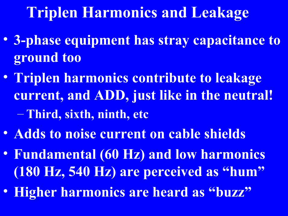
Triplen Harmonics and Leakage • 3-phase equipment has stray capacitance to
ground too• Triplen harmonics contribute to leakage
current, and ADD, just like in the neutral!– Third, sixth, ninth, etc
• Adds to noise current on cable shields • Fundamental (60 Hz) and low harmonics
(180 Hz, 540 Hz) are perceived as “hum”• Higher harmonics are heard as “buzz”

Line Filters Contribute Noise to Ground

Line Filters Attenuate RF Noise

Performance Depends on Impedances

Ground Fault Circuit Interrupter• Senses imbalance
between phase (hot) and neutral current
• Difference is flowing to ground
• Interrupts circuit if > 4-6 mA
• Required in locations where shock hazard more likely (outdoors, around plumbing)

Pin 1 in Cable-Mounted Connectors
• Pin 1 is the shield contact of XL connectors (AES14-1992)
• No connection shall be made to the shell of cable-mounted connectors (AES54-1)

Pin 1 Within Equipment • Pin 1 is the shield contact of XL connectors• Cable shields shall go to the shielding
enclosure (and ONLY to the shielding enclosure) (AES48)
• If shields go inside the box (to the circuit board, for example), common impedances couple shield current at random points along the circuit board!
• Noise is added to the signal

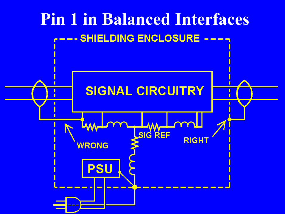
Pin 1 in Balanced Interfaces
Pin 1 in Balanced Interfaces

How Does It Happen?

How Does It Happen? • Pin 1 of XL’s go to chassis via circuit board
and ¼” connectors (it’s cheaper)• XLR shell not connected to anything! • RCA connectors not connected to chassis

The G terminal goes to the enclosure, right?
Well, sort of, but it’s a long and torturous journey!
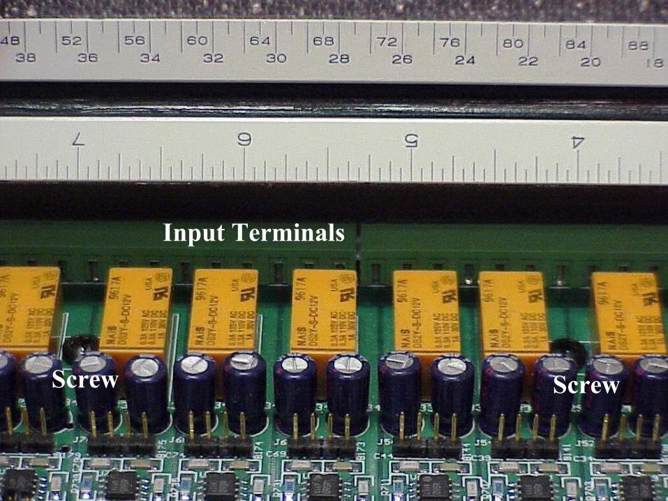
Screw Screw
Input Terminals

The Right Way – A screw to connect the shields

Power Supply Pin 1-Like Problem

Power Supply Pin 1-Like Problems
• It buzzes when I turn it on, and there are no signal wires plugged in
• Power line leakage current flows through circuit common– Stray capacitance in power transformer– Line filter capacitors
• Power supply filter capacitor returns via signal common bus

Pin 1 in Unbalanced Interfaces

Where are the Chassis Connections for this laptop’s sound card?
• Hint: It isn’t an audio connector shell! – That metal is a shield, but not connected to
connectors– And the cover is plastic too

Where are the Chassis Connections for this laptop’s sound card?
Yes, it’s the DB9, DB15, and DB25 shells!

Testing for Pin 1 Problems

John Wendt’s “Hummer” Test for Pin 1 Problems
• Drive pin 1• Listen to the output• If you hear it, you have a problem

Cable construction is part of the problem!
• No cable is perfect– Inductive imbalance (SCIN)–Capacitive imbalance– Imperfect shielding (tiny openings in
braid)• Even small imperfections become more
important at higher frequencies–No effect on audio–BIG effect on RF Interference

Foil/Drain Shield
Braid/Drain Shield
Braid/Foil Shield

The drain wire is coupled more closely to the white conductor
So shield current induces more voltage on white than violet

Inductive Imbalance
• Below about 5 MHz, most shield current in a foil/drain shield flows in the drain wire
• As a result of cable construction, the drain wire couples more closely to one signal conductor than the other

Primary Coupling Mechanisms• IR drop couples shield current in
unbalanced interfaces • Pin 1 problems couple shield current in
balanced and unbalanced interfaces• Cable imbalance couples shield current to
a balanced signal pair
• Minimizing shield current is a key to preventing this noise!

Technical Grounding• The primary purpose of technical
grounding is to minimize the flow of power-related noise currents on the shields of signal wiring, while also providing the equipment grounding required for safety
• Technical grounding should also provide a suitable reference for cable and equipment shields at radio frequencies

Technical Grounding• Isolated Star (Single point) – The technical
system is bonded to system ground only at a single point; equipment is isolated from random contact with ground, and bonded to the breaker panel via a dedicated conductor run with the power conductors
• Mesh (Multipoint) – a well controlled grid or mesh is established, all building elements and all technical equipment are bonded to it at every possible point
• Random – Use what the power system gives you

Technical Grounding• Single point grounding usually provides
the greatest noise immunity at low frequencies (below 3 MHz)
• Mesh (multipoint) grounding usually provides the greatest immunity at high frequencies
• Hybrid grounding provides both – cable shields have dc connection at one end, capacitive connection at other end– Shield current flows at RF, but not at AF– Common mode voltage minimized at inputs

Single Point (Isolated Star) GroundingDevice
ADevice
BDevice
CDevice
D
Device G
Device F
Device E Device
H

Mesh GroundingDevice
ADevice
BDevice
CDevice
D
Device G
Device F
Device E Device
H

Conceptual Mesh Architecture
From Williams and Armstrong, “EMC for Systems and Installations” Newnes, 2000

Conceptual Mesh Architecture
From Williams and Armstrong, “EMC for Systems and Installations” Newnes, 2000

Structure is Bonded to Mesh
From Williams and Armstrong, “EMC for Systems and Installations” Newnes, 2000

Single Point Grounding• Since the technical system has only one
connection to other grounds, low frequency current on its ground conductors is limited to: – its own leakage currents– magnetic induction on loops that include its
ground conductors

Single Point Grounding• Generally far superior for audio systems • Much less costly than a proper mesh,
especially for a retrofit• Keeps low frequency ground currents
away from technical systems• Principal costs are:
– Isolated ground outlets– Isolated ground conductor to each outlet– Isolated mounting of equipment racks, video
projectors, wireless mic antennas, etc.

Mesh Grounding• Since the technical system has many
connection to other grounds, low frequency currents on ground conductors divide between many parallel paths, so IR drops are much smaller
• All cables are run in close proximity to grounded structures along their entire length, so induced currents tend to be diverted to those grounded structures

Mesh Grounding• A good choice for large video studios
– Many copper braid shields• Many parallel paths to divide current• Video cables have low shield resistance
– Only one or two audio and video signals are “on the air” at one time, so little coherent addition
• Coherent addition can occur: – If there are pin 1 problems (audio or video)– If the studio does live production with many
live mics and analog distribution at mic level
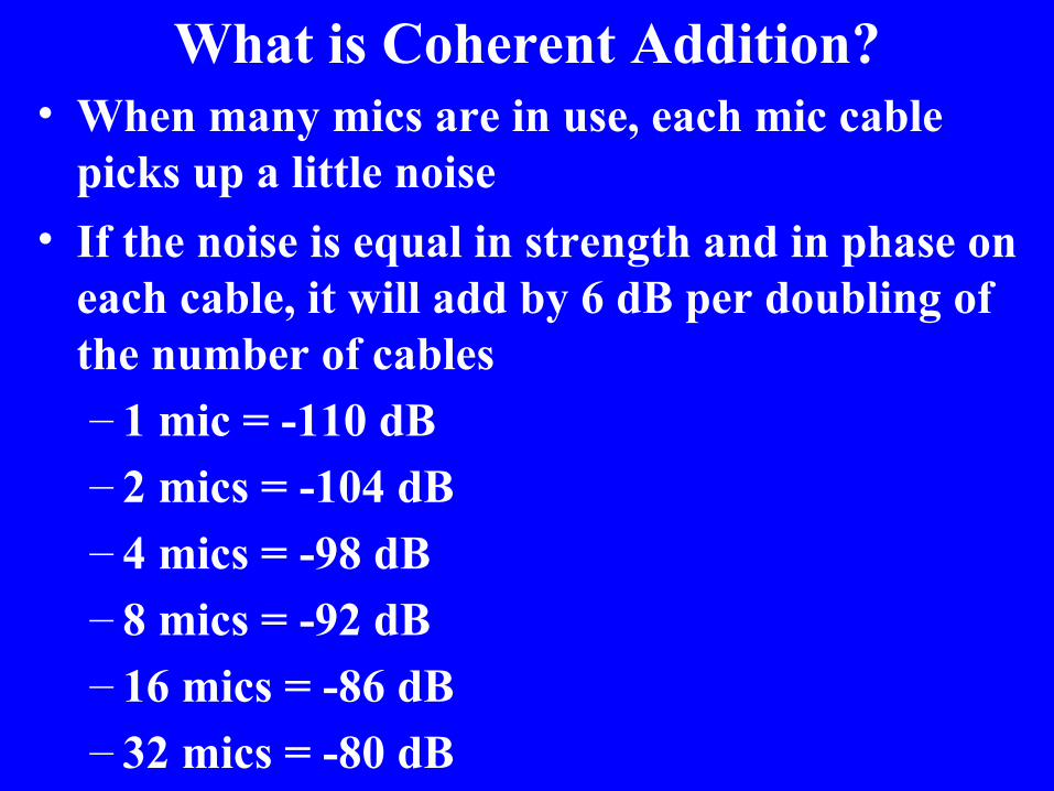
What is Coherent Addition?• When many mics are in use, each mic cable
picks up a little noise• If the noise is equal in strength and in phase on
each cable, it will add by 6 dB per doubling of the number of cables– 1 mic = -110 dB– 2 mics = -104 dB– 4 mics = -98 dB– 8 mics = -92 dB– 16 mics = -86 dB– 32 mics = -80 dB

Mesh Grounding• A good choice for facilities that handle
only digital signals and data– No low frequency components of signal, so
low frequency noise is easily rejected if system bandwidth is properly limited
• A poor choice for most audio systems and small video systems– Baseband noise appears on cable shields and
cannot be removed by filtering

Mesh Grounding• Mesh grounding is expensive to do
properly–All structure and conductive elements
must be bonded to it–Retrofitting impractical–A very close-spaced mesh is required
for good performance above HF• While power-related ground currents
divide between multiple paths, those currents can be very large, so ground potentials can still be problematic
Isolated Ground Systems

Isolated Ground Systems• All system elements isolated from ground
–Racks– Interconnecting cables –Antennas–Cameras–Projectors–Microphones
• All equipment enclosures bonded to a single grounded point (the “star point”)

Single Point (Isolated Star) Grounding
Device A
Device B
Device C
Device D
Device G
Device F
Device E
Device H

Power Wiring in Isolated Ground Systems
Grounded Enclosure
Grounded Conduit

Power Wiring in Isolated Ground Systems
Equipment Rack, Isolated from Grounded Objects(Concrete is conductive!)
COPPER GROUND BUSS, BONDED TO RACK
STANDARD OUTLET, BONDED TO RACK
GROUNDED CONDUIT
INSULATING BUSHING

Rack Grounding in Isolated Ground Systems

Signal Wiring• Isolated Ground Systems• Mesh Ground Systems

Balanced Line Level Wiring in Isolated Ground Systems
• Cable shields bonded only to equipment enclosure at either end–Always bond shield at sending end– At receiving end, bond may be omitted, or
may be made through a capacitor (hybrid grounding)

Balanced Microphone Level Wiring in Isolated Ground Systems
• Cable shields bonded only to equipment enclosure at both ends– Shield continuity required for phantom
power

Definition – Wiring Panel• A wiring panel is an enclosure, usually
metal, that houses connectors for connecting equipment to an audio or video system, for example:–Mic inputs–Line inputs and outputs–Video inputs and outputs–Speaker outputs–Control lines
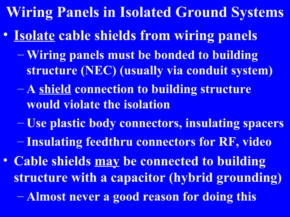
Wiring Panels in Isolated Ground Systems• Isolate cable shields from wiring panels
– Wiring panels must be bonded to building structure (NEC) (usually via conduit system)
– A shield connection to building structure would violate the isolation
– Use plastic body connectors, insulating spacers– Insulating feedthru connectors for RF, video
• Cable shields may be connected to building structure with a capacitor (hybrid grounding)– Almost never a good reason for doing this

Equipment in Isolated Ground Systems• Isolate equipment from building structure
– Racks– Mixing Equipment– Projectors– Cameras– Antennas
• Use Isolated Ground Power for all equipment– Equipment properly grounded by IG wiring

Local Bonding• Reduces Noise Between Equipment
–Reduces Noise on Unbalanced Wiring–Less Current to Excite Pin 1 Problems
• Can improve all types of technical ground systems
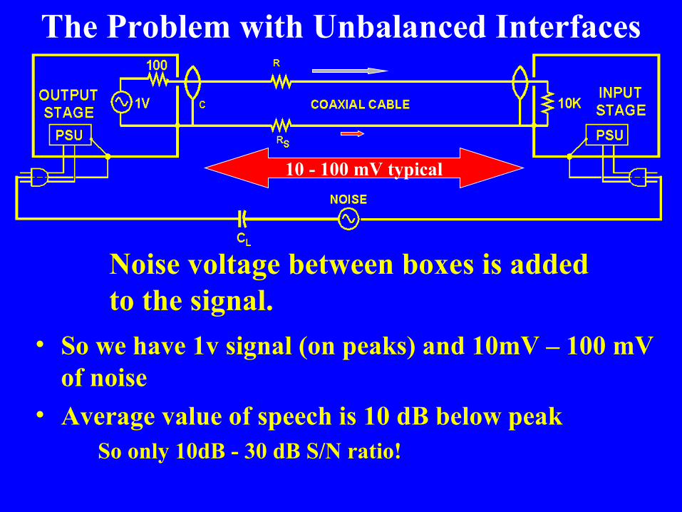
The Problem with Unbalanced Interfaces
• So we have 1v signal (on peaks) and 10mV – 100 mV of noise
• Average value of speech is 10 dB below peak So only 10dB - 30 dB S/N ratio!
Noise voltage between boxes is added to the signal.
10 - 100 mV typical

The Problem with Unbalanced Interfaces
10 - 100 mV typical
Noise voltage between boxes is added to the signal, and also excites Pin 1 Problems.
What if we could reduce the noise between boxes?

Power System Ground Wiring (The “Green Wire”)
BREAKER
PANEL
OUTLET MIXDESK
OUTLET EFX RACK
5 Ft #18
5 Ft #18
150 Ft #1232 mΩ
32 mΩ
300 mΩ
150 Ft #12300 mΩ

Power System Ground Wiring (The “Green Wire”)
BREAKER
PANEL
OUTLET MIXDESK
OUTLET EFX RACK
5 Ft #18
5 Ft #18
150 Ft #1232 mΩ
32 mΩ
300 mΩ
150 Ft #12300 mΩ
10mA = 3 mV
50mA = 15 mV
10mA = 0.32 mV
10mA = 0.32 mV
These leakage currents are sine waves distorted by the pulses recharging power supply filter capacitors!

Power System Ground Wiring (The “Green Wire”)
BREAKER
PANEL
OUTLET
EFXRACKOUTLET
MIXDESK
5 Ft #18
5 Ft #18
150 Ft #1232 mΩ
32 mΩ
300 mΩ
150 Ft #12300 mΩ
10mA = 3 mV
50mA = 15 mV
10mA = 0.32 mV
50mA = 1.6 mV
16mV
Noise currents are complex and different in each product, so
how they add is unpredictable

Local Bonding Step #1
BREAKER
PANEL
OUTLET
EFXRACKOUTLET
HOUSEMIX
5 Ft #18
5 Ft #18
32 mΩ
32 mΩ150 Ft #12300 mΩ
60mA = 18 mV
10mA = 0.32 mV
50mA = 1.6 mV
1.5mV
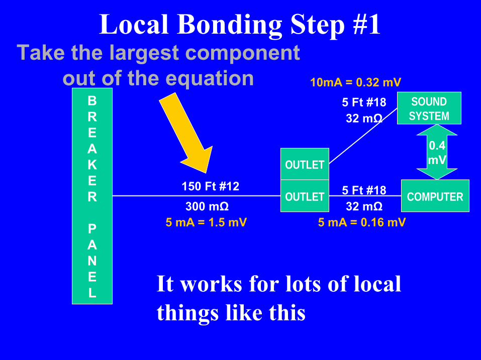
Take the largest component out of the equation

Local Bonding Step #1• This reduces the voltage between outlets
to a few microvolts • What’s left are the IR drops on line cords
within your racks and mix position• Step #1 is typically good for 20 dB

Local Bonding Step #1• Put all power outlets for the mix position
in portable quad boxes that are bonded together– A 20A circuit can run almost any mix position– If you need more outlets, bolt multiple quad
boxes together
Local Bonding Step #1
BREAKER
PANEL
OUTLET
COMPUTEROUTLET
SOUNDSYSTEM
5 Ft #18
5 Ft #18
32 mΩ
32 mΩ150 Ft #12300 mΩ
5 mA = 1.5 mV
10mA = 0.32 mV
5 mA = 0.16 mV
0.4mV
Take the largest component out of the equation
It works for lots of local things like this

Local bondingstep #1 reduces this voltage, but not enough
Local Bonding Step #1
So we need step #2

• Short out the remaining noise (or reduce IR drop) by adding a BIG conductor between the equipment enclosures
• 50µV would yield 76 dB S/R ratio• 5µV would yield 96 dB S/R ratio
50 µVHeavy braid
Local Bonding Step #2

Local Bonding Step #2• Bond all interconnected equipment
together with heavy copper braid• In our Mix Position example
–Mix Desk to Signal Processing–Signal Processing to Signal Processing –Mix Desk to Equipment Patched to
Inserts

Equipment Bonding – A House Mix Position
MixConsole
SystemRack
PatchableEffectsRack
Most Critical

Guidelines For Local Bonding• Add bonding in parallel with every
unbalanced audio path• Bonding should be #6 copper or larger
– Copper braid stripped from heavy coax (RG8, RG11, RG213, RG214) is #10 AWG
– Enclose in heat shrink to reduce corrosion– Multiple #10 THHN stranded conductors work,
but are stiffer• Bond to chassis of equipment
– Retaining screw of D-connector on laptops

Guidelines For Local Bonding• Noise reduction = 20 log (R2/R1)
• -6 dB for cutting resistance in half! –Double the conductor size = -6 dB–Half the length = -6 dB
• Think BIG and SHORT!• Take advantage of conductive racks
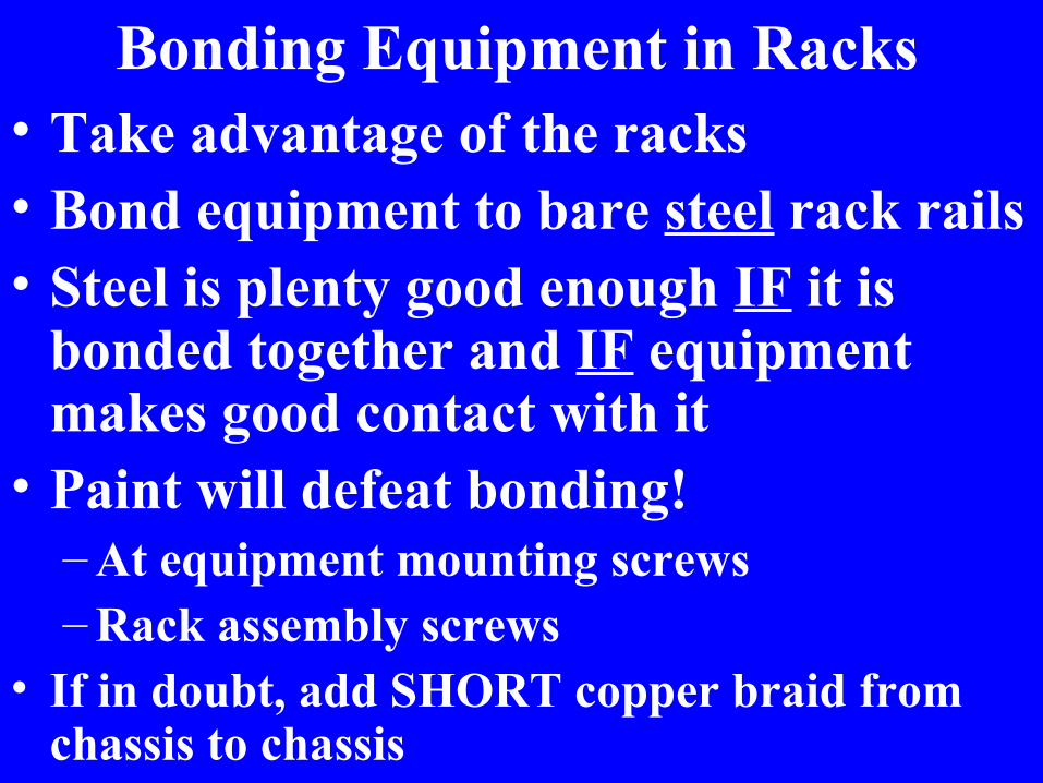
Bonding Equipment in Racks• Take advantage of the racks• Bond equipment to bare steel rack rails• Steel is plenty good enough IF it is
bonded together and IF equipment makes good contact with it
• Paint will defeat bonding! – At equipment mounting screws– Rack assembly screws
• If in doubt, add SHORT copper braid from chassis to chassis
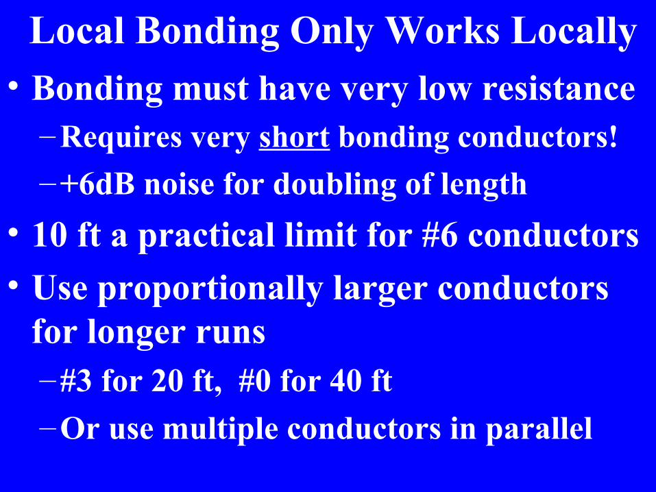
Local Bonding Only Works Locally• Bonding must have very low resistance
– Requires very short bonding conductors! –+6dB noise for doubling of length
• 10 ft a practical limit for #6 conductors• Use proportionally larger conductors
for longer runs–#3 for 20 ft, #0 for 40 ft–Or use multiple conductors in parallel

How Well Does This Work?

We Started With This
Measured between equipment with no bonding
-34.3 dBu (16 mV)
60Hz
120
300180 540

Noise Spectrum on “Ground” After Bonding
Measured between equipment with only heavy braid bonding it together
-83.6 dBu (0.05 mV)

Noise Reduction From Bonding
-34.3 dBu (16 mV)
-49 dB Better-83.6 dBu (0.05 mV)

A Portable Isolated Ground System• All power outlets for mix position in portable
quad boxes that are bonded together– A 20A circuit can run most mix positions– Extend that circuit from the amp racks! – To add outlets, bolt multiple quad boxes
together, add 2nd 20A circuit if needed– Do not bond these to ground locally– Ground for the mix position is the ground
carried from the amp racks!
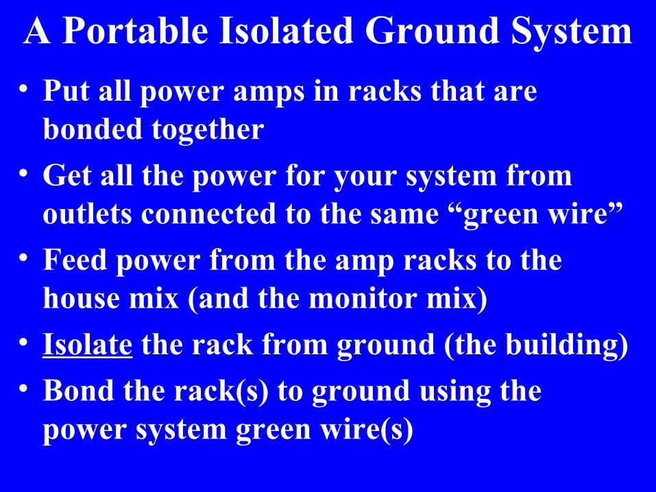
• Put all power amps in racks that are bonded together
• Get all the power for your system from outlets connected to the same “green wire”
• Feed power from the amp racks to the house mix (and the monitor mix)
• Isolate the rack from ground (the building) • Bond the rack(s) to ground using the
power system green wire(s)
A Portable Isolated Ground System

Shielding and Grounding• Shielding and grounding are often confused• This class is not really about shielding, but
we’ll talk about it a bit as a BONUS!

Fields and Shielding • When there are no wires in common
between the noise source and the victim system, noise coupling can occur by means of a field.
• Coupling by fields can be just as strong as (or stronger than) coupling by a direct connection

Fields• Magnetic field
–Surrounds a wire carrying current• Electric field
–Force (voltage) between two charged conductors
• Electromagnetic field (radio wave)–Combination of magnetic and electric
fields at right angles to each other• Virtually all power-related fields are magnetic

Magnetic Field • Produced by current flowing in a wire
– Could be part of a motor, a transformer, or just wiring that makes up a power system
– Strength proportional to current– Strength proportional to loop area
• Change in field induces voltage in a wire passing through the field (inductive coupling)– Current will flow in that wire if there is a
complete circuit – Strength proportional to loop area– Strength falls off with distance

Reducing Magnetic Field Interference • Minimize the loop area (both source and victim)• Increase distance between source and victim• Use balanced wiring with twisted pairs
– Source or victim or both (additive)• Use coax with beefy copper shield if you must
run unbalanced• Shield with a magnetic material (steel, mumetal)
• Cable shields provide no magnetic shielding

Electric Field • Produced by voltage between two conductors
– Mostly confined to the space between them• Induces voltage onto a conductor in or near
that space (capacitive coupling)

Electromagnetic Field • Produced by antennas carrying RF
current –Travels through space–Follows inverse square law
• Coupled to our wiring by antenna action–That is, our wiring acts as a receiving
antenna

Solving Electric and Electromagnetic Field Interference
• Increase the distance between source and victim
• Use balanced wiring with twisted pairs• Use coaxial cable with high % coverage
shield• Shield the equipment and the wiring
– Cable shields DO work on Electric and Electromagnetic fields

Magnetic Field Noise Sources • Conductors carrying large currents
– Power system feeders– Lighting system wiring
• Transformers• Motors• Especially variable speed drive motors
–HVAC systems–Elevators–Geothermal systems

A Double-Bonded Neutral Creates An Interfering Magnetic Field

Fields with Single-Bonded Neutral
• Field mostly confined to the very small area between conductors – that is, within the conduit
LoadField only here
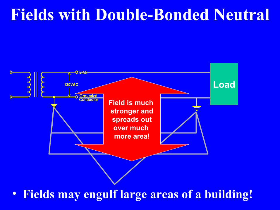
Fields with Double-Bonded Neutral
Load
Field is much stronger andspreads outover much more area!
• Fields may engulf large areas of a building!

Magnetic Fields “On the Loose” • Couple noise currents onto any
conductors within the field–Audio cables–Video cables–Control cables–Computer interface cables–Single coil guitar pickups–Dynamic mics without hum-bucking coils

Variable-Speed Drive Motors
Current Loop Current Loop
Current Loop

Variable-Speed Drive Motors• Operates by chopping DC into a variable
width pulse– 10-20 kHz typical switching frequencies– Harmonics extend to hundreds of kHz
• Stray capacitance (and filter capacitors) between motor and ground causes very large currents to flow on grounded structure– Establishes a very large current loop
• Controllers often widely separated from motors to make installation easier

Variable-Speed Drive Motors
Current Loop Current Loop
Current Loop

Variable-Speed Drive Motor Solutions
• Minimize the size of the current loops– Locate transformer, controller, and motor
in closest possible proximity to each other– Transformer should have delta primary,
wye secondary, bonded very close to motor • Prevents feeders to transformer from
being part of the current loop– Twist neutral and phase conductors

Reasons for Using Conduit
• Physical protection of wiring–Reduces long term maintenance costs
• Make installation (and upgrades) easier• Shielding

Conduit and Shielding• Electric field
–Continuous and conductive• Magnetic field
–Continuous and ferrous material (steel)• Steel conduit is the only practical
magnetic shielding for our wiring• Continuous includes any junction
boxes and couplings in the path

Antenna and Cable TV Systems• Should enter the building near the power
system earth bond and should be bonded to it by the shortest possible path
• Bond should be outside the building if possible
• Add isolator inside the building after the bond (to avoid leakage current on audio and video wiring)

Antenna and Cable TV Systems

Telephone Lines• They are a common lightning target, so
need a good arrester and short bond to the building bonding point
• Poor bonding is common • Lightning doesn’t know the installer
was in a different trade union or covered by a lax safety code

Troubleshooting Tools• Ammeters
–Current Probes• Volt-Ohmeter
–Low Ohms Scale Important• Magnetic Field Probe• Radio Receiver• Headphone Amplifier • Battery Powered Scope


Snake Oil and other Bad Medicine

Ground Lifts – Bad Medicine• Breaks equipment
ground path• Prevents breaker
from blowing if chassis becomes “hot”
• Can KILL someone
X

Ground Lifts – Bad Medicine• Breaks equipment
ground path• Prevents breaker
from blowing if chassis becomes “hot”
• Can KILL someone
X

Ground Isolators – Bad Medicine
Inductance can delay breaker action, someone can die before it blows!
R is too large to blow fuseGround Isolator

Ground Isolators – Bad Medicine
Inductance can delay breaker action, someone can die before it blows!
R is too large to blow fuseGround Isolator
X

All Ground Electrodes Must be Bonded Together
• Isolated does not mean “separated”

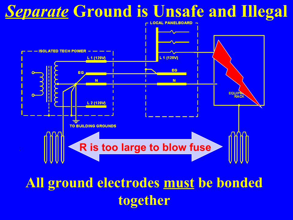
Separate Ground is Unsafe and Illegal
Separate Ground is Unsafe and Illegal
All ground electrodes must be bonded together
R is too large to blow fuse

Separate Ground is Unsafe and Illegal
All ground electrodes must be bonded together
R is too large to blow fuseX

Power Isolation TransformerDiverts noise away from secondary (good)
but adds it to safety ground, where it increases leakage currents (bad)

Power Isolation TransformerDiverts noise away from secondary (good)
but adds it to safety ground, where it increases leakage currents (bad)X

Power Isolation TransformerUse a good one only to establish the technical power system, but not downstream
Single Faraday Shield Two Faraday Shields
Ralph Morrison, “Grounding and Shielding Techniques”

“Balanced” Power• Symmetrical power seems like a good idea
– 120-volts between two 60-volt legs– In ideal world, it would completely cancel
leakage currents into safety ground system• But not in the real world• Predicted benefits based on false
assumptions

“Balanced Power”
Neutral
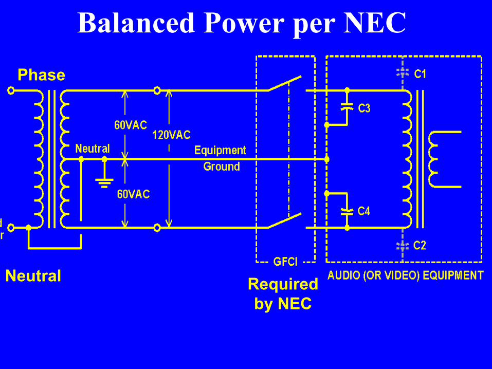
Balanced Power per NECPhase
Neutral Required by NEC
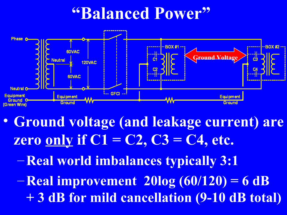
“Balanced Power”
• Ground voltage (and leakage current) are zero only if C1 = C2, C3 = C4, etc.– Real world imbalances typically 3:1– Real improvement 20log (60/120) = 6 dB
+ 3 dB for mild cancellation (9-10 dB total)
Ground Voltage

“Balanced Power”• Actual noise reduction generally less
than 10 dB and rarely exceeds 15 dB–May be cost-effective in certain video
applications (video is far less demanding than audio)
• Isolated ground systems can provide more than 30 dB noise reduction – And IG systems are a lot less expensive
• Local bonding can provide an additional 20-40 dB noise reduction

Noise Reduction From IG Wiring
-34.3 dBu (16 mV)
-67 dBu (0.32 mV)
-32.7 dB Better
Balanced Power – A Field View• With ordinary un-balanced power, fields from
“hot” and neutral currents cancel at any reasonable distance from the wiring – Balanced power does not improve on that
• With ordinary un-balanced power, an unbalanced field exists between phase (hot) and neutral, but this field also falls off quickly with distance– Balanced power balances that field. BUT:– Power system noise is coupled by magnetic
fields, not electric fields!

Snake Oil – Exotic Power Cords• Branch circuit wiring typically 75 ft of #14
– 1.13 volt drop with 3A load– 3.78 volt drop with 10A load
• Common IEC power cord is 6 ft of #18– 0.23 volt drop with 3A load– 0.77 volt drop with 10A load
• Total voltage drop– 1.46 volts (118.54 V at outlet) with 3A load– 4.55 volts (115.45 V at outlet) with 10A load
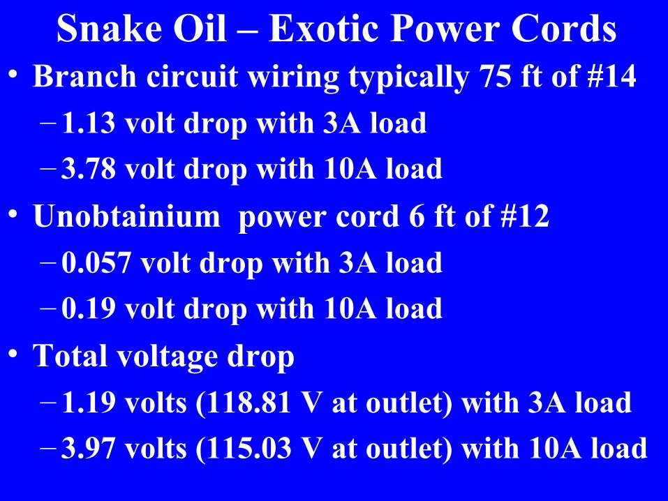
Snake Oil – Exotic Power Cords• Branch circuit wiring typically 75 ft of #14
– 1.13 volt drop with 3A load– 3.78 volt drop with 10A load
• Unobtainium power cord 6 ft of #12– 0.057 volt drop with 3A load– 0.19 volt drop with 10A load
• Total voltage drop– 1.19 volts (118.81 V at outlet) with 3A load– 3.97 volts (115.03 V at outlet) with 10A load

Plain Ordinary Copper• Change branch circuit wiring to #12
– .715 volt drop with 3A load– 2.38 volt drop with 10A load
• Common IEC power cord 6 ft of #18– 0.23 volt drop with 3A load– 0.77 volt drop with 10A load
• Total voltage drop– .945 volts (119.05 V at outlet) with 3A load– 3.15 volts (116.85 V at outlet) with 10A load

About Surge Suppression• Mindless use of MOV suppressors can
actually increase equipment damage risk• MOV’s are shunt-mode devices that
divert surges onto the equipment ground system
• Surges generate brief but extreme extreme voltage differences in the safety ground system
• Equipment interfaces are often damaged

How MOV’s Cause Failures• An MOV between phase and equipment
ground raises the equipment ground to a very high voltage at the point where is is connected
• An MOV between phase and equipment ground at a different outlet raises the equipment ground at that outlet to a different very high voltage
• If equipment plugged in at these locations is interconnected by low voltage wiring, it will see the difference of the two high voltages.

MOV’s Often Fail Destructively• MOV’s are sacrificial – they fail after they have
conducted a certain number of joules!– They often short, and blow a fuse– They often open, and give no indication of
failure– They may partially degrade, losing their ability
to conduct the surge– On a sufficiently high voltage surge, they can
explode– And they can catch fire!
• But they are cheap, so they’re everywhere!

A Good Use for MOV Suppressors• Use professional-grade unit at the service
entrance to protect an entire building• MOV’s divert surge to the main building
common ground bonding point• The ground reference for the entire
building goes up with a surge• Minimizes likelihood of equipment damage
because gradients between grounds exist only due to the lightning field, not due to pollution of equipment ground

What the UL Label Means• Nearly all UL testing is for safety
–Fire, flame spread, noxious fumes–Electrical shock hazards
• Surge suppressors are usually listed under UL 1449 and tested only for safety (that is, to verify that they won’t start a fire)
• The effectiveness of surge suppressors is verified by adjunct testing under UL 1449– Very few products are adjunct tested– Few would pass

Real Surge Protection• To protect from lightning induced surges,
install devices at main power service entry• To protect sub-circuits or equipment, use
series-mode suppressors– Presents a high impedance to the surge– Does not dump current into safety ground

Series-Mode Suppression • Stores the surge in reactive components, then
discharges it slowly back onto the line• Not cheap ~ $250 - $500/branch circuit
NEMA Boxes
Rack Mount
“Brick”

Power and Grounding for Audio and Video Systems
Jim Brownhttp://audiosystemsgroup.com
Andy Bentonhttp://www.surgex.com
Recommended