Polymer microstructured optical fibers for terahertz wave guiding
Bora Ung, Anna Mazhorova, Alexandre Dupuis, Mathieu Rozé, and Maksim
Skorobogatiy*
Department of Engineering Physics, Ecole Polytechnique de Montréal, C.P 6079, succ. Centre-Ville, Montreal,
Quebec, H3C 3A,7 Canada * [email protected]
www.photonics.phys.polymtl.ca
Abstract: We outline the most recent technological advancements in the
design, fabrication and characterization of polymer microstructured optical
fibers (MOFs) for applications in the terahertz waveband. Focusing on
specific experimental demonstrations, we show that polymer optical fibers
provide a very flexible route towards THz wave guiding. Crucial incentives
include the large variety of the low-cost and relatively low absorption loss
polymers, the facile fiber preform fabrication by molding, drilling, stacking
and extrusion, and finally, the simple fabrication through fiber drawing at
low forming temperatures.
©2011 Optical Society of America
OCIS codes: (060.2280) Fiber design and fabrication; (060.4005) Microstructured fibers;
(160.5470) Polymers; (110.6795) Terahertz imaging; (300.6495) Spectroscopy, terahertz.
References and links
1. G. Imeshev, M. E. Fermann, K. L. Vodopyanov, M. M. Fejer, X. Yu, J. S. Harris, D. Bliss, and C. Lynch, “High-
power source of THz radiation based on orientation-patterned GaAs pumped by a fiber laser,” Opt. Express
14(10), 4439–4444 (2006).
2. M. Tang, H. Minamide, Y. Wang, T. Notake, S. Ohno, and H. Ito, “Dual-wavelength single-crystal double-pass
KTP optical parametric oscillator and its application in terahertz wave generation,” Opt. Lett. 35(10), 1698–1700
(2010).
3. Y. Cai, I. Brener, J. Lopata, J. Wynn, L. Pfeiffer, J. B. Stark, Q. Wu, X. C. Zhang, and J. F. Federici, “Coherent
terahertz radiation detection: Direct comparison between free-space electro-optic sampling and antenna
detection,” Appl. Phys. Lett. 73(4), 444–446 (1998).
4. N. Karpowicz, J. Chen, T. Tongue, and X.-C. Zhang, “Coherent millimetre wave to mid-infrared measurements
with continuous bandwidth reaching 40 THz,” Electron. Lett. 44(8), 544–545 (2008).
5. C. Jansen, S. Wietzke, O. Peters, M. Scheller, N. Vieweg, M. Salhi, N. Krumbholz, C. Jördens, T. Hochrein, and
M. Koch, “Terahertz imaging: applications and perspectives,” Appl. Opt. 49(19), E48–E57 (2010).
6. S. Zhong, Y.-C. Shen, L. Ho, R. K. May, J. A. Zeitler, M. Evans, P. F. Taday, M. Pepper, T. Rades, K. C.
Gordon, R. Müller, and P. Kleinebudde, “Non-destructive quantification of pharmaceutical tablet coatings using
terahertz pulsed imaging and optical coherence tomography,” Opt. Lasers Eng. 49(3), 361–365 (2011).
7. G. J. Wilmink, B. L. Ibey, T. Tongue, B. Schulkin, N. Laman, X. G. Peralta, C. C. Roth, C. Z. Cerna, B. D.
Rivest, J. E. Grundt, and W. P. Roach, “Development of a compact terahertz time-domain spectrometer for the
measurement of the optical properties of biological tissues,” J. Biomed. Opt. 16(4), 047006 (2011).
8. Y.-S. Jin, G.-J. Kim, and S.-Y. Jeon, “Terahertz dielectric properties of polymers,” J. Korean Phys. Soc. 49, 513–
517 (2006).
9. A. Dupuis, K. Stoeffler, B. Ung, C. Dubois, and M. Skorobogatiy, “Transmission measurements of hollow-core
THz Bragg Fibers,” J. Opt. Soc. Am. B 28(4), 896–907 (2011).
10. P. D. Cunningham, N. N. Valdes, F. A. Vallejo, L. M. Hayden, B. Polishak, X.-H. Zhou, J. Luo, A. K. Jen, J. C.
Williams, and R. J. Twieg, “Broadband terahertz characterization of the refractive index and absorption of some
important polymeric and organic electro-optic materials,” J. Appl. Phys. 109(4), 043505 (2011).
11. M. Skorobogatiy and J. Yang, Fundamentals of Photonic Crystal Guiding (Cambridge University Press, 2009).
12. L.-J. Chen, H.-W. Chen, T.-F. Kao, J.-Y. Lu, and C.-K. Sun, “Low-loss subwavelength plastic fiber for terahertz
waveguiding,” Opt. Lett. 31(3), 308–310 (2006).
13. J.-Y. Lu, C.-C. Kuo, C.-M. Chiu, H.-W. Chen, Y.-J. Hwang, C.-L. Pan, and C.-K. Sun, “THz interferometric
imaging using subwavelength plastic fiber based THz endoscopes,” Opt. Express 16(4), 2494–2501 (2008).
14. C.-M. Chiu, H.-W. Chen, Y.-R. Huang, Y.-J. Hwang, W.-J. Lee, H.-Y. Huang, and C.-K. Sun, “All-terahertz
fiber-scanning near-field microscopy,” Opt. Lett. 34(7), 1084–1086 (2009).
#155808 - $15.00 USD Received 30 Sep 2011; revised 18 Nov 2011; accepted 22 Nov 2011; published 7 Dec 2011(C) 2011 OSA 12 December 2011 / Vol. 19, No. 26 / OPTICS EXPRESS B848
15. M. Nagel, A. Marchewka, and H. Kurz, “Low-index discontinuity terahertz waveguides,” Opt. Express 14(21),
9944–9954 (2006).
16. A. Hassani, A. Dupuis, and M. Skorobogatiy, “Low loss porous terahertz fibers containing multiple
subwavelength holes,” Appl. Phys. Lett. 92(7), 071101 (2008).
17. A. Hassani, A. Dupuis, and M. Skorobogatiy, “Porous polymer fibers for low-loss Terahertz guiding,” Opt.
Express 16(9), 6340–6351 (2008).
18. A. Dupuis, J.-F. Allard, D. Morris, K. Stoeffler, C. Dubois, and M. Skorobogatiy, “Fabrication and THz loss
measurements of porous subwavelength fibers using a directional coupler method,” Opt. Express 17(10), 8012–
8028 (2009).
19. A. Dupuis, A. Mazhorova, F. Désévédavy, M. Rozé, and M. Skorobogatiy, “Spectral characterization of porous
dielectric subwavelength THz fibers fabricated using a microstructured molding technique,” Opt. Express
18(13), 13813–13828 (2010).
20. S. Atakaramians, S. Afshar V, H. Ebendorff-Heidepriem, M. Nagel, B. M. Fischer, D. Abbott, and T. M. Monro,
“THz porous fibers: design, fabrication and experimental characterization,” Opt. Express 17(16), 14053–15062
(2009).
21. H. Ebendorff-Heidepriem and T. M. Monro, “Extrusion of complex preforms for microstructured optical fibers,”
Opt. Express 15(23), 15086–15092 (2007).
22. K. Nielsen, H. K. Rasmussen, A. J. L. Adam, P. C. M. Planken, O. Bang, and P. U. Jepsen, “Bendable, low-loss
Topas fibers for the terahertz frequency range,” Opt. Express 17(10), 8592–8601 (2009).
23. O. Mitrofanov and J. A. Harrington, “Dielectric-lined cylindrical metallic THz waveguides: mode structure and
dispersion,” Opt. Express 18(3), 1898–1903 (2010).
24. M. Rozé, B. Ung, A. Mazhorova, M. Walther, and M. Skorobogatiy, “Suspended core subwavelength fibers:
towards practical designs for low-loss terahertz guidance,” Opt. Express 19(10), 9127–9138 (2011).
25. C.-H. Lai, B. You, J.-Y. Lu, T.-A. Liu, J.-L. Peng, C.-K. Sun, and H.-C. Chang, “Modal characteristics of
antiresonant reflecting pipe waveguides for terahertz waveguiding,” Opt. Express 18(1), 309–322 (2010).
26. S. Johnson, M. Ibanescu, M. Skorobogatiy, O. Weisberg, T. Engeness, M. Soljacic, S. Jacobs, J. Joannopoulos,
and Y. Fink, “Low-loss asymptotically single-mode propagation in large-core OmniGuide fibers,” Opt. Express
9(13), 748–779 (2001).
27. M. Skorobogatiy and A. Dupuis, “Ferroelectric all-polymer hollow Bragg fibers for terahertz guidance,” Appl.
Phys. Lett. 90(11), 113514 (2007).
28. B. Ung, A. Dupuis, K. Stoeffler, C. Dubois, and M. Skorobogatiy, “High-refractive-index composite materials
for terahertz waveguides: trade-off between index contrast and absorption loss,” J. Opt. Soc. Am. B 28(4), 917–
921 (2011).
29. K. Nielsen, H. K. Rasmussen, P. U. Jepsen, and O. Bang, “Porous-core honeycomb bandgap THz fiber,” Opt.
Lett. 36(5), 666–668 (2011).
30. S. Atakaramians, S. V. Afshar, M. Nagel, H. K. Rasmussen, O. Bang, T. M. Monro, and D. Abbott, “Direct
probing of evanescent fields for characterization of porous terahertz fibers,” Appl. Phys. Lett. 98, 121104 (2011).
31. A. Dupuis, Dielectric THz waveguides (PhD thesis, Ecole Polytechnique de Montréal, 2010).
32. O. Mitrofanov, T. Tan, P. R. Mark, B. Bowden, and J. A. Harrington, “Waveguide mode imaging and dispersion
analysis with terahertz near-field microscopy,” Appl. Phys. Lett. 94(17), 171104 (2009).
33. J. R. Knab, A. J. L. Adam, R. Chakkittakandy, and P. C. M. Planken, “Terahertz near-field microspectroscopy,”
Appl. Phys. Lett. 97(3), 031115 (2010).
34. A. Bitzer, A. Ortner, and M. Walther, “Terahertz near-field microscopy with subwavelength spatial resolution
based on photoconductive antennas,” Appl. Opt. 49(19), E1–E6 (2010).
35. M. Walther and A. Bitzer, “Electromagnetic Wave Propagation Close to Microstructures Studied by Time and
Phase-Resolved THz Near-Field Imaging,” J. Infrared Millim. Terahz. Waves 32(8-9), 1020–1030 (2011).
1. Introduction
The last decade has seen significant technical advances in the generation [1,2] and detection
[3,4] of terahertz waves. Robust and compact pulsed and continuous-wave terahertz sources
are now commercially available, and complete THz spectroscopy and imaging setups are now
seeing market introduction [5–7]. However most of these THz systems are based on the bulky
free-space-optics that require expert alignment and servicing, thus restricting the end-user
appeal of these systems. One part of the solution, as distinctly demonstrated at telecom
wavelengths, is to replace the free-space optical components with flexible optical fibers as the
links between the individual optical components. The latter approach should result in a
dramatic increase of the system performance and reliability, and a high level of integration for
THz systems. Therefore, the development of the low-loss, low-dispersion, broadband THz
fibers constitutes a key enabling component towards a new generation of applications for THz
technology. The rationale for using plastics for making waveguides are many: they constitute
#155808 - $15.00 USD Received 30 Sep 2011; revised 18 Nov 2011; accepted 22 Nov 2011; published 7 Dec 2011(C) 2011 OSA 12 December 2011 / Vol. 19, No. 26 / OPTICS EXPRESS B849
cheap and widely accessible materials, have a facile low-temperature processing, and exhibit
relatively low losses when compared to other dielectrics in the terahertz spectral range.
In this contribution, we provide an overview of the latest technological progress in the
design, fabrication and characterization of polymer microstructured optical fibers (MOFs) and
polymer photonic bandgap (PBG) fibers for the guiding of terahertz waves. We first outline
the main challenges for THz waveguiding and next present a selection of plastic MOFs and
PBG fibers of various types that demonstrate promising results.
2. Main challenges of the plastic-based THz fiber optics
2.1 Losses
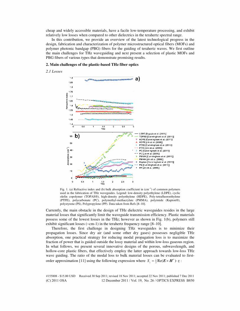
Fig. 1. (a) Refractive index and (b) bulk absorption coefficient in (cm−1) of common polymers
used in the fabrication of THz waveguides. Legend: low-density polyethylene (LDPE), cyclic
olefin copolymer (TOPAS®), high-density polyethylene (HDPE), Poly-tetrafluoroethylene
(PTFE), polycarbonate (PC), polymethyl-methacrylate (PMMA), polyimide (Kapton®),
polystyrene (PS), Polypropylene (PP). Data taken from Refs [8–10].
Currently, the main obstacle in the design of THz dielectric waveguides resides in the large
material losses that significantly limit the waveguide transmission efficiency. Plastic materials
possess some of the lowest losses in the THz; however as shown in Fig. 1(b), polymers still
exhibit significant losses (~cm-1) in the terahertz frequency range [8–10].
Therefore, the first challenge in designing THz waveguides is to minimize their
propagation losses. Since dry air (and some other dry gases) possesses negligible THz
absorption, one practical strategy for reducing modal propagation loss is to maximize the
fraction of power that is guided outside the lossy material and within low-loss gaseous region.
In what follows, we present several innovative designs of the porous, subwavelength, and
hollow-core plastic fibers, that effectively employ the latter approach towards low-loss THz
wave guiding. The ratio of the modal loss to bulk material losses can be evaluated to first-
order approximation [11] using the following expression where 1
2Re( )
zS
∗= × ⋅E H z :
#155808 - $15.00 USD Received 30 Sep 2011; revised 18 Nov 2011; accepted 22 Nov 2011; published 7 Dec 2011(C) 2011 OSA 12 December 2011 / Vol. 19, No. 26 / OPTICS EXPRESS B850
( )
2
matmode mat
mattotal
Re
2z
n dAf
S dAα
αα
⋅= =
∫∫
E
(1)
Solid core subwavelength fibers
One of the simplest plastic fibers that provide for a high fraction of power in the low-loss
regions is the subwavelength core fiber introduced by Chen et al. [12] and effectively used in
signal delivery and imaging applications [13,14]. The fiber is a simple plastic wire having
circular cross-section of subwavelength diameter. This step-index fiber allows single-mode
HE11 operation via total internal reflection guiding mechanism. Due to the subwavelength
diameter of the solid core, the fundamental guided mode has a strong presence in the low-loss
air cladding [see Fig. 2(c)].
Porous core subwavelength fibers
It was demonstrated by Nagel et al. [15] that inserting a subwavelength-sized hole in the
middle of an otherwise solid dielectric core leads to a significant enhancement of the modal
fields in the gas-filled hole, and as a consequence, reduction in the waveguide losses. The
authors explained the strong field presence in the subwavelength hole using the continuity of
transverse component of the electric displacement field at the air/dielectric interface. Taking
one step further, it was recently proposed theoretically by Hassani et al. [16,17] and then
demonstrated experimentally [18–20] that incorporation of an array of deeply-subwavelength
holes in the core of a subwavelength fiber [see Fig. 2(a)] enables to further reduce the fiber
propagation losses compared to those of a solid core fiber of similar diameter.
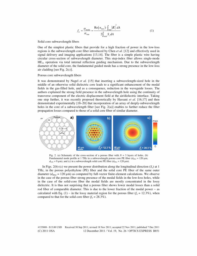
Fig. 2. (a) Schematic of the cross-section of a porous fiber with N = 3 layers of holes. (b)
Fundamental mode profile at 1 THz in a subwavelength porous core PE fiber (dfiber = 120 µm,
dhole = 9 µm), and (c) in a subwavelength solid core PE fiber (dfiber = 120 µm).
In Figs. 2(b)-(c) we present the power distribution along the longitudinal direction (Sz) at 1
THz, in the porous polyethylene (PE) fiber and the solid core PE fiber of the same outer
diameter (dfiber = 120 µm) as computed by full-vector finite-element calculations. We observe
in the case of the porous fiber strong presence of the modal fields in the low-loss holes, while
in the case of the solid-core fiber the modal fields are mostly concentrated in the lossy
dielectric. It is thus not surprising that a porous fiber shows lower modal losses than a solid
rod fiber of comparable diameter. This is due to the lower fraction of the modal power − as
calculated with Eq. (1) − in the lossy material region for the porous fiber (fα = 12.3%), when
compared to that for the solid core fiber (fα = 28.3%).
#155808 - $15.00 USD Received 30 Sep 2011; revised 18 Nov 2011; accepted 22 Nov 2011; published 7 Dec 2011(C) 2011 OSA 12 December 2011 / Vol. 19, No. 26 / OPTICS EXPRESS B851
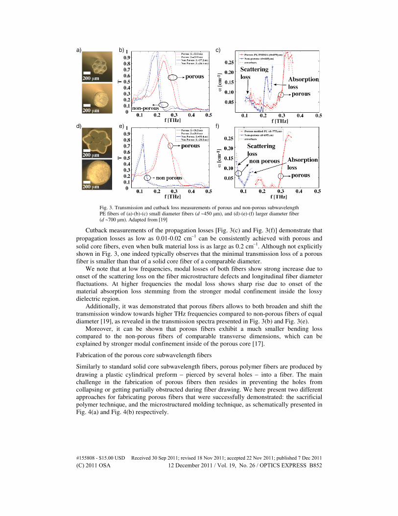
Fig. 3. Transmission and cutback loss measurements of porous and non-porous subwavelength
PE fibers of (a)-(b)-(c) small diameter fibers (d ~450 µm), and (d)-(e)-(f) larger diameter fiber
(d ~700 µm). Adapted from [19]
Cutback measurements of the propagation losses [Fig. 3(c) and Fig. 3(f)] demonstrate that
propagation losses as low as 0.01-0.02 cm−1
can be consistently achieved with porous and
solid core fibers, even when bulk material loss is as large as 0.2 cm−1
. Although not explicitly
shown in Fig. 3, one indeed typically observes that the minimal transmission loss of a porous
fiber is smaller than that of a solid core fiber of a comparable diameter.
We note that at low frequencies, modal losses of both fibers show strong increase due to
onset of the scattering loss on the fiber microstructure defects and longitudinal fiber diameter
fluctuations. At higher frequencies the modal loss shows sharp rise due to onset of the
material absorption loss stemming from the stronger modal confinement inside the lossy
dielectric region.
Additionally, it was demonstrated that porous fibers allows to both broaden and shift the
transmission window towards higher THz frequencies compared to non-porous fibers of equal
diameter [19], as revealed in the transmission spectra presented in Fig. 3(b) and Fig. 3(e).
Moreover, it can be shown that porous fibers exhibit a much smaller bending loss
compared to the non-porous fibers of comparable transverse dimensions, which can be
explained by stronger modal confinement inside of the porous core [17].
Fabrication of the porous core subwavelength fibers
Similarly to standard solid core subwavelength fibers, porous polymer fibers are produced by
drawing a plastic cylindrical preform − pierced by several holes − into a fiber. The main
challenge in the fabrication of porous fibers then resides in preventing the holes from
collapsing or getting partially obstructed during fiber drawing. We here present two different
approaches for fabricating porous fibers that were successfully demonstrated: the sacrificial
polymer technique, and the microstructured molding technique, as schematically presented in
Fig. 4(a) and Fig. 4(b) respectively.
#155808 - $15.00 USD Received 30 Sep 2011; revised 18 Nov 2011; accepted 22 Nov 2011; published 7 Dec 2011(C) 2011 OSA 12 December 2011 / Vol. 19, No. 26 / OPTICS EXPRESS B852
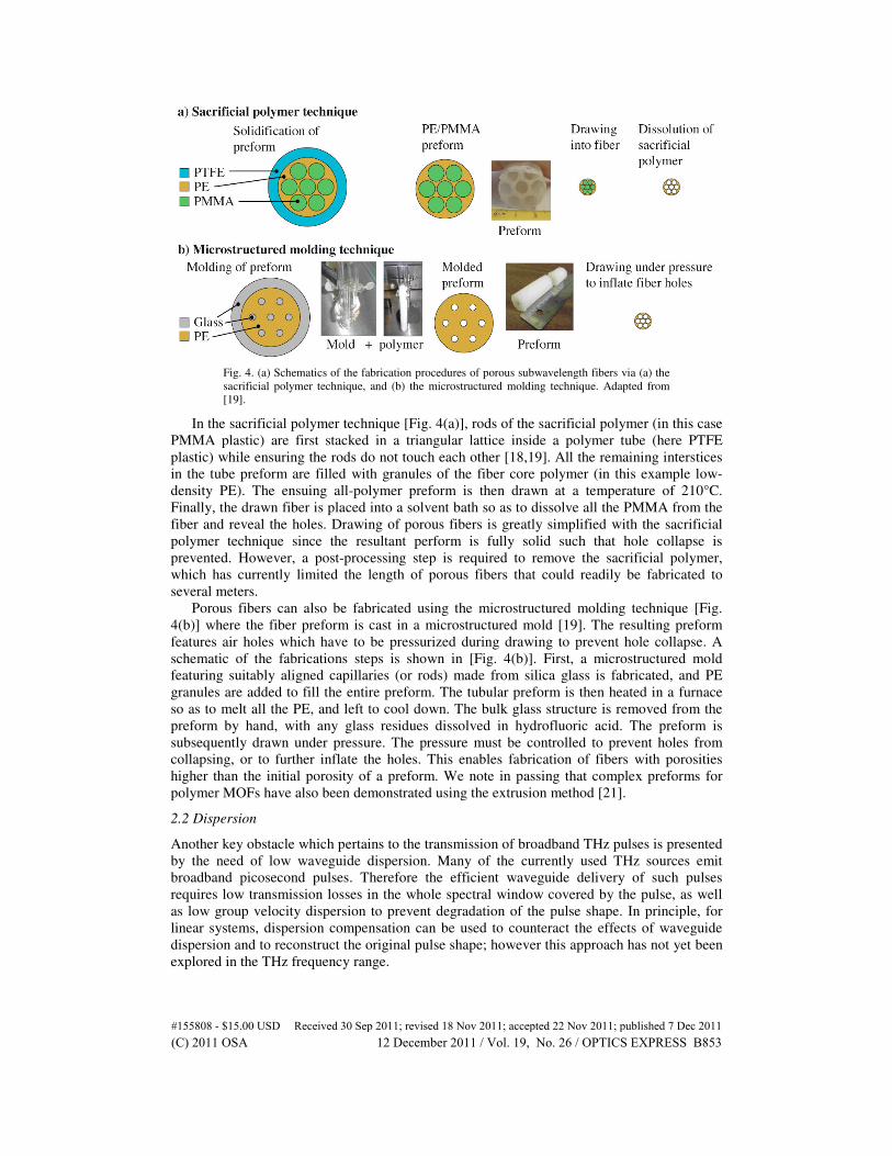
Fig. 4. (a) Schematics of the fabrication procedures of porous subwavelength fibers via (a) the
sacrificial polymer technique, and (b) the microstructured molding technique. Adapted from
[19].
In the sacrificial polymer technique [Fig. 4(a)], rods of the sacrificial polymer (in this case
PMMA plastic) are first stacked in a triangular lattice inside a polymer tube (here PTFE
plastic) while ensuring the rods do not touch each other [18,19]. All the remaining interstices
in the tube preform are filled with granules of the fiber core polymer (in this example low-
density PE). The ensuing all-polymer preform is then drawn at a temperature of 210°C.
Finally, the drawn fiber is placed into a solvent bath so as to dissolve all the PMMA from the
fiber and reveal the holes. Drawing of porous fibers is greatly simplified with the sacrificial
polymer technique since the resultant perform is fully solid such that hole collapse is
prevented. However, a post-processing step is required to remove the sacrificial polymer,
which has currently limited the length of porous fibers that could readily be fabricated to
several meters.
Porous fibers can also be fabricated using the microstructured molding technique [Fig.
4(b)] where the fiber preform is cast in a microstructured mold [19]. The resulting preform
features air holes which have to be pressurized during drawing to prevent hole collapse. A
schematic of the fabrications steps is shown in [Fig. 4(b)]. First, a microstructured mold
featuring suitably aligned capillaries (or rods) made from silica glass is fabricated, and PE
granules are added to fill the entire preform. The tubular preform is then heated in a furnace
so as to melt all the PE, and left to cool down. The bulk glass structure is removed from the
preform by hand, with any glass residues dissolved in hydrofluoric acid. The preform is
subsequently drawn under pressure. The pressure must be controlled to prevent holes from
collapsing, or to further inflate the holes. This enables fabrication of fibers with porosities
higher than the initial porosity of a preform. We note in passing that complex preforms for
polymer MOFs have also been demonstrated using the extrusion method [21].
2.2 Dispersion
Another key obstacle which pertains to the transmission of broadband THz pulses is presented
by the need of low waveguide dispersion. Many of the currently used THz sources emit
broadband picosecond pulses. Therefore the efficient waveguide delivery of such pulses
requires low transmission losses in the whole spectral window covered by the pulse, as well
as low group velocity dispersion to prevent degradation of the pulse shape. In principle, for
linear systems, dispersion compensation can be used to counteract the effects of waveguide
dispersion and to reconstruct the original pulse shape; however this approach has not yet been
explored in the THz frequency range.
#155808 - $15.00 USD Received 30 Sep 2011; revised 18 Nov 2011; accepted 22 Nov 2011; published 7 Dec 2011(C) 2011 OSA 12 December 2011 / Vol. 19, No. 26 / OPTICS EXPRESS B853
Chromatic dispersion of the group velocity is typically quantified using the coefficient β2
(in ps/THz/cm) corresponding to the second order term in the Taylor expansion of the modal
propagation constant β with respect to the frequency of operation:
2
eff eff
2 2
2 dn d n
c d c d
ωβ
ω ω= + (2)
where 2 fω π= and eff
Re( )n cβ ω= ⋅ denotes the real part of the effective refractive index
of the mode. If the initial pulse is Gaussian with the pulse width 0τ , after propagating along
the length L of a dispersive waveguide, the output pulse is a broadened Gaussian with a new
width 0
LDτ τ∆ ∼ .
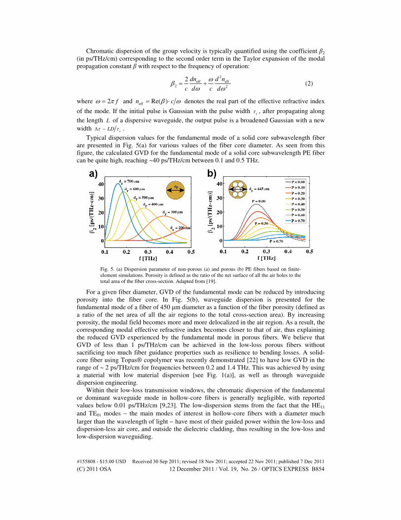
Typical dispersion values for the fundamental mode of a solid core subwavelength fiber
are presented in Fig. 5(a) for various values of the fiber core diameter. As seen from this
figure, the calculated GVD for the fundamental mode of a solid core subwavelength PE fiber
can be quite high, reaching ~40 ps/THz/cm between 0.1 and 0.5 THz.
Fig. 5. (a) Dispersion parameter of non-porous (a) and porous (b) PE fibers based on finite-
element simulations. Porosity is defined as the ratio of the net surface of all the air holes to the
total area of the fiber cross-section. Adapted from [19].
For a given fiber diameter, GVD of the fundamental mode can be reduced by introducing
porosity into the fiber core. In Fig. 5(b), waveguide dispersion is presented for the
fundamental mode of a fiber of 450 µm diameter as a function of the fiber porosity (defined as
a ratio of the net area of all the air regions to the total cross-section area). By increasing
porosity, the modal field becomes more and more delocalized in the air region. As a result, the
corresponding modal effective refractive index becomes closer to that of air, thus explaining
the reduced GVD experienced by the fundamental mode in porous fibers. We believe that
GVD of less than 1 ps/THz/cm can be achieved in the low-loss porous fibers without
sacrificing too much fiber guidance properties such as resilience to bending losses. A solid-
core fiber using Topas® copolymer was recently demonstrated [22] to have low GVD in the
range of ~ 2 ps/THz/cm for frequencies between 0.2 and 1.4 THz. This was achieved by using
a material with low material dispersion [see Fig. 1(a)], as well as through waveguide
dispersion engineering.
Within their low-loss transmission windows, the chromatic dispersion of the fundamental
or dominant waveguide mode in hollow-core fibers is generally negligible, with reported
values below 0.01 ps/THz/cm [9,23]. The low-dispersion stems from the fact that the HE11
and TE01 modes − the main modes of interest in hollow-core fibers with a diameter much
larger than the wavelength of light − have most of their guided power within the low-loss and
dispersion-less air core, and outside the dielectric cladding, thus resulting in the low-loss and
low-dispersion waveguiding.
#155808 - $15.00 USD Received 30 Sep 2011; revised 18 Nov 2011; accepted 22 Nov 2011; published 7 Dec 2011(C) 2011 OSA 12 December 2011 / Vol. 19, No. 26 / OPTICS EXPRESS B854
2.3 Packaging of subwavelength fibers
While a highly delocalized field is favorable for lowering absorption losses in the material; on
the other hand it is a major inconvenience when handling the fiber during normal operation
because of the strong perturbation induced to the mode through direct manipulation of the
fiber or via holders (such as strings and other apparatus) used for maintaining the fiber into
position. Hence the issue of core encapsulation is crucial for subwavelength dielectric fibers.
There are two principal incentives for encapsulating the solid/porous core of a fiber within
an outer polymer tube as shown in Fig. 6. First, the solid tubular cladding confers greater
mechanical stability and shielding for the subwavelength-sized core, thus allowing smaller
bending radii and protection against the accumulation of dust and other surface contaminants.
Second, the outer tube cladding prevents the highly delocalized core-guided mode from
interacting with the surrounding environment, thus eliminating cross-talk noise with adjacent
waveguides, and perturbation-induced losses incurred by direct manipulation of the fibers or
due to fiber holders. Moreover, core encapsulation opens the way for the simple and
economical purging of the low volume tube cladding with dry air so as to eliminate losses due
to water vapor typically present in the ambient environment.
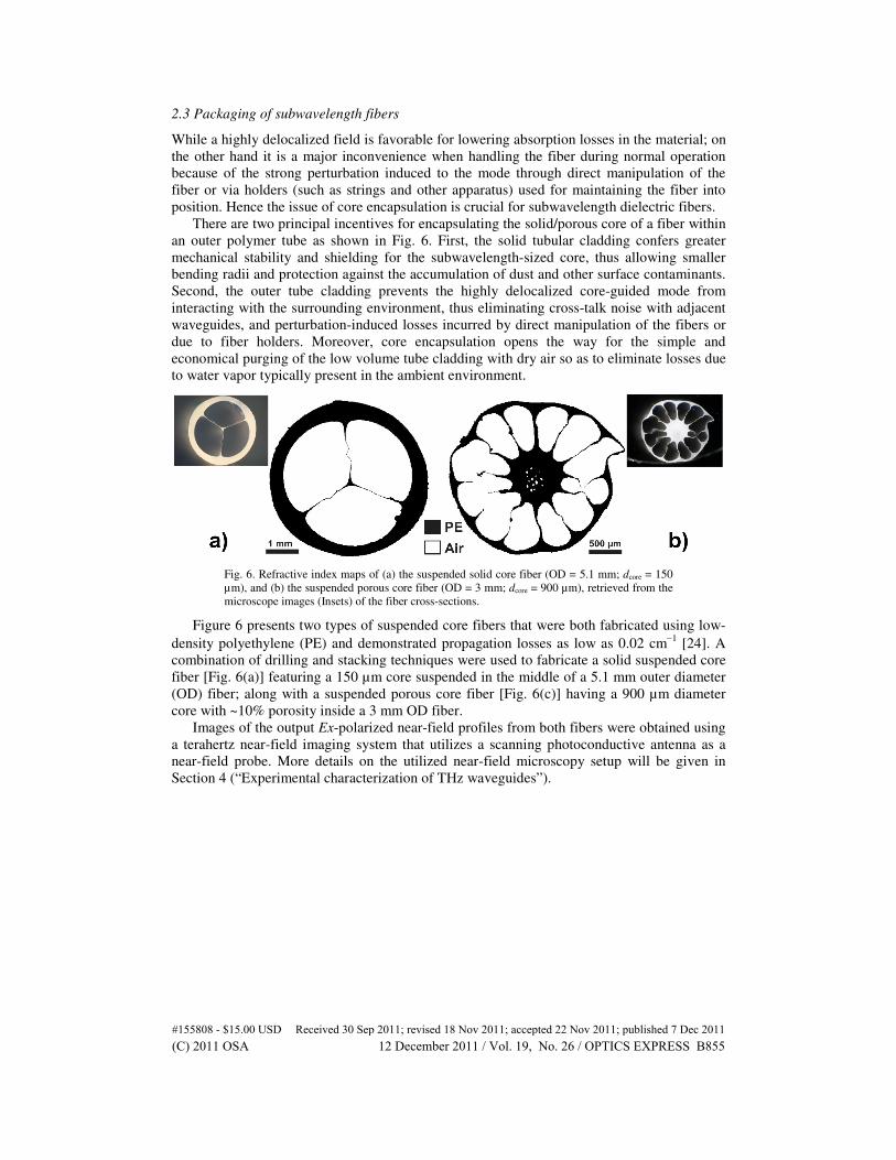
Fig. 6. Refractive index maps of (a) the suspended solid core fiber (OD = 5.1 mm; dcore = 150
µm), and (b) the suspended porous core fiber (OD = 3 mm; dcore = 900 µm), retrieved from the
microscope images (Insets) of the fiber cross-sections.
Figure 6 presents two types of suspended core fibers that were both fabricated using low-
density polyethylene (PE) and demonstrated propagation losses as low as 0.02 cm−1
[24]. A
combination of drilling and stacking techniques were used to fabricate a solid suspended core
fiber [Fig. 6(a)] featuring a 150 µm core suspended in the middle of a 5.1 mm outer diameter
(OD) fiber; along with a suspended porous core fiber [Fig. 6(c)] having a 900 µm diameter
core with ~10% porosity inside a 3 mm OD fiber.
Images of the output Ex-polarized near-field profiles from both fibers were obtained using
a terahertz near-field imaging system that utilizes a scanning photoconductive antenna as a
near-field probe. More details on the utilized near-field microscopy setup will be given in
Section 4 (“Experimental characterization of THz waveguides”).
#155808 - $15.00 USD Received 30 Sep 2011; revised 18 Nov 2011; accepted 22 Nov 2011; published 7 Dec 2011(C) 2011 OSA 12 December 2011 / Vol. 19, No. 26 / OPTICS EXPRESS B855
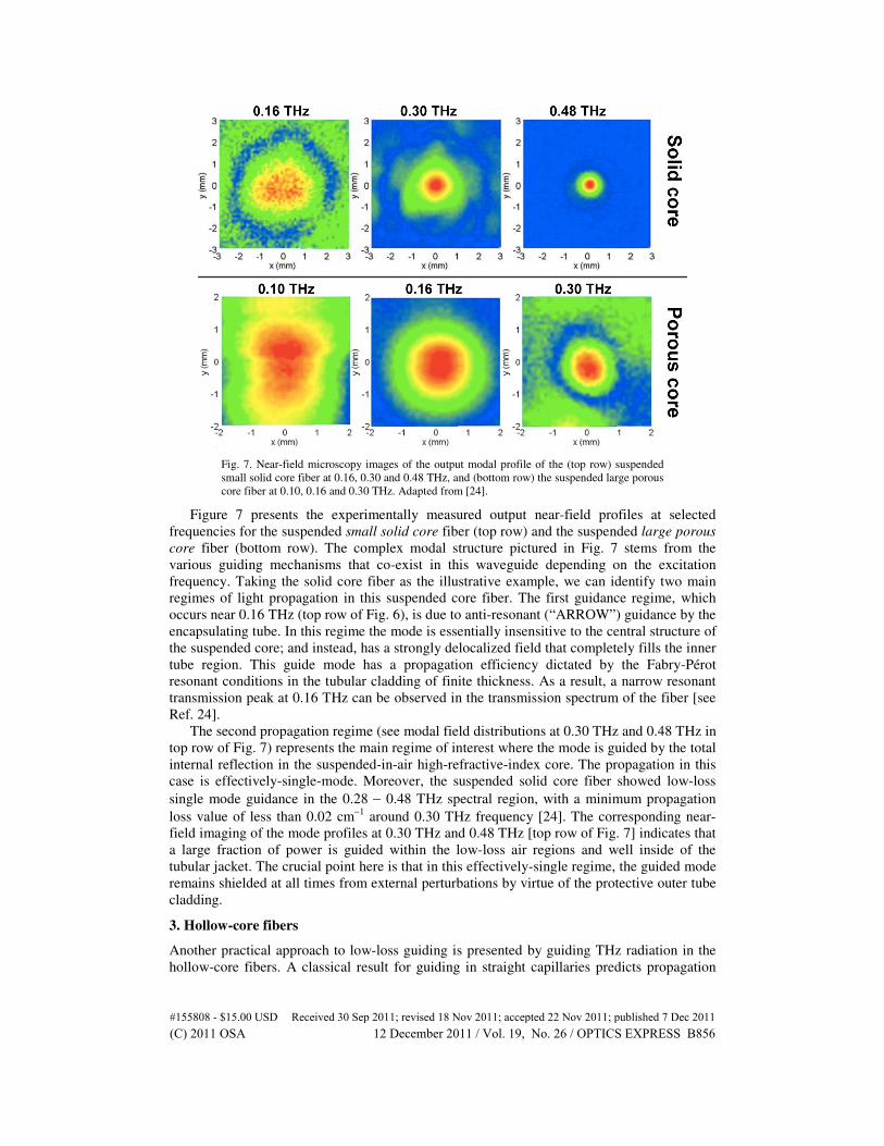
Fig. 7. Near-field microscopy images of the output modal profile of the (top row) suspended
small solid core fiber at 0.16, 0.30 and 0.48 THz, and (bottom row) the suspended large porous
core fiber at 0.10, 0.16 and 0.30 THz. Adapted from [24].
Figure 7 presents the experimentally measured output near-field profiles at selected
frequencies for the suspended small solid core fiber (top row) and the suspended large porous
core fiber (bottom row). The complex modal structure pictured in Fig. 7 stems from the
various guiding mechanisms that co-exist in this waveguide depending on the excitation
frequency. Taking the solid core fiber as the illustrative example, we can identify two main
regimes of light propagation in this suspended core fiber. The first guidance regime, which
occurs near 0.16 THz (top row of Fig. 6), is due to anti-resonant (“ARROW”) guidance by the
encapsulating tube. In this regime the mode is essentially insensitive to the central structure of
the suspended core; and instead, has a strongly delocalized field that completely fills the inner
tube region. This guide mode has a propagation efficiency dictated by the Fabry-Pérot
resonant conditions in the tubular cladding of finite thickness. As a result, a narrow resonant
transmission peak at 0.16 THz can be observed in the transmission spectrum of the fiber [see
Ref. 24].
The second propagation regime (see modal field distributions at 0.30 THz and 0.48 THz in
top row of Fig. 7) represents the main regime of interest where the mode is guided by the total
internal reflection in the suspended-in-air high-refractive-index core. The propagation in this
case is effectively-single-mode. Moreover, the suspended solid core fiber showed low-loss
single mode guidance in the 0.28 − 0.48 THz spectral region, with a minimum propagation
loss value of less than 0.02 cm−1
around 0.30 THz frequency [24]. The corresponding near-
field imaging of the mode profiles at 0.30 THz and 0.48 THz [top row of Fig. 7] indicates that
a large fraction of power is guided within the low-loss air regions and well inside of the
tubular jacket. The crucial point here is that in this effectively-single regime, the guided mode
remains shielded at all times from external perturbations by virtue of the protective outer tube
cladding.
3. Hollow-core fibers
Another practical approach to low-loss guiding is presented by guiding THz radiation in the
hollow-core fibers. A classical result for guiding in straight capillaries predicts propagation
#155808 - $15.00 USD Received 30 Sep 2011; revised 18 Nov 2011; accepted 22 Nov 2011; published 7 Dec 2011(C) 2011 OSA 12 December 2011 / Vol. 19, No. 26 / OPTICS EXPRESS B856
losses scaling as λ2/a
3 with the bore radius a. Therefore in principle, propagation losses can be
set arbitrarily low simply by enlarging the bore diameter. However, the downside of
increasing the bore diameter is in the increased bending losses and the highly multimode
guidance resulting in a low spatial quality of the guided beams.
3.1 Anti-resonant reflecting optical fibers
The first type of hollow-core fiber consists of a thin tube that guides using anti-resonant
reflections from its walls to confine the light in the hollow core. Such fibers are typically
referred as ARROW waveguide for “anti-resonant reflecting optical waveguide” [25]. Making
use of a simple Fabry-Pérot resonator model, one can predict the periodic spacing between
two adjacent resonant frequencies in the fiber transmission spectrum [25]:
2 2
,2 clad core
cf
t n n∆ =
− (3)
where ncore and nclad respectively designate the refractive indices of the gaseous core (usually
air) and that of the polymer tube cladding, while c is the light velocity in vacuum, and t stands
for the wall thickness of the tube cladding. From Eq. (3) we note that the periodic spacing
between two resonant frequencies is inversely proportional to the wall thickness. Hence, in an
ARROW fiber, in order to obtain the widest spectral separation between two resonant
frequencies (and consequently the widest transmission windows) it is necessary to have the
thinnest possible wall, often below sub-millimeter dimensions.
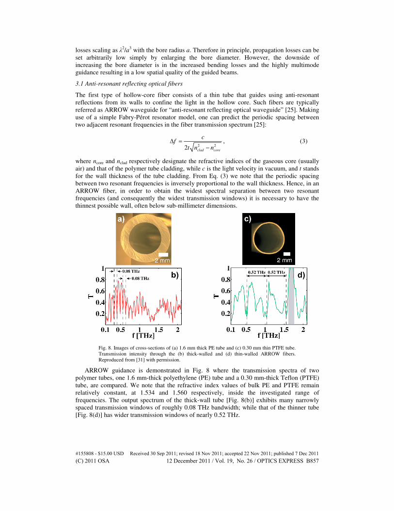
Fig. 8. Images of cross-sections of (a) 1.6 mm thick PE tube and (c) 0.30 mm thin PTFE tube.
Transmission intensity through the (b) thick-walled and (d) thin-walled ARROW fibers.
Reproduced from [31] with permission.
ARROW guidance is demonstrated in Fig. 8 where the transmission spectra of two
polymer tubes, one 1.6 mm-thick polyethylene (PE) tube and a 0.30 mm-thick Teflon (PTFE)
tube, are compared. We note that the refractive index values of bulk PE and PTFE remain
relatively constant, at 1.534 and 1.560 respectively, inside the investigated range of
frequencies. The output spectrum of the thick-wall tube [Fig. 8(b)] exhibits many narrowly
spaced transmission windows of roughly 0.08 THz bandwidth; while that of the thinner tube
[Fig. 8(d)] has wider transmission windows of nearly 0.52 THz.
#155808 - $15.00 USD Received 30 Sep 2011; revised 18 Nov 2011; accepted 22 Nov 2011; published 7 Dec 2011(C) 2011 OSA 12 December 2011 / Vol. 19, No. 26 / OPTICS EXPRESS B857
3.2 Bragg fibers
The main drawbacks of thin-walled tubes are that they are challenging to fabricate, highly
fragile and very sensitive to external perturbations while handling them. An alternative and
more robust solution to light confinement in the hollow core, namely Bragg fibers, exploits
resonant reflections from a periodic multilayer reflector surrounding the hollow core region.
The periodic reflectors in Bragg fibers are composed of two alternating dielectrics featuring a
high-refractive-index contrast [example in Fig. 9(a)] in order to maximize fiber transmission
bandwidth [26]. The potential of all-polymer Bragg fibers for the transmission of terahertz
light was first identified [27] and later achieved in [9]. The transmission characteristics of
Bragg fibers are mainly determined by the first few layers in the reflector adjacent to the
hollow core. Bragg fibers can therefore have a thick cladding that confers greater mechanical
stability and lower sensitivity to the environment compared to the thin-walled ARROW
fibers.
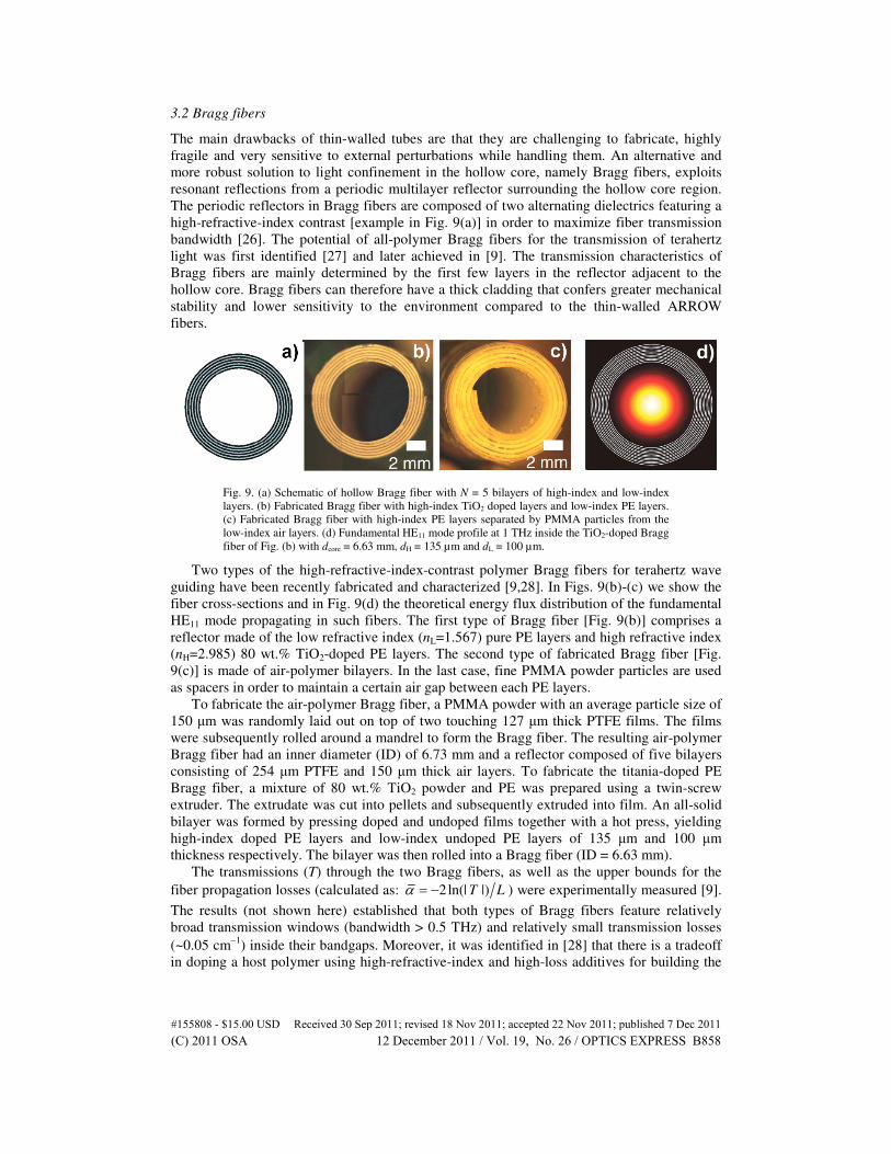
Fig. 9. (a) Schematic of hollow Bragg fiber with N = 5 bilayers of high-index and low-index
layers. (b) Fabricated Bragg fiber with high-index TiO2 doped layers and low-index PE layers.
(c) Fabricated Bragg fiber with high-index PE layers separated by PMMA particles from the
low-index air layers. (d) Fundamental HE11 mode profile at 1 THz inside the TiO2-doped Bragg
fiber of Fig. (b) with dcore = 6.63 mm, dH = 135 µm and dL = 100 µm.
Two types of the high-refractive-index-contrast polymer Bragg fibers for terahertz wave
guiding have been recently fabricated and characterized [9,28]. In Figs. 9(b)-(c) we show the
fiber cross-sections and in Fig. 9(d) the theoretical energy flux distribution of the fundamental
HE11 mode propagating in such fibers. The first type of Bragg fiber [Fig. 9(b)] comprises a
reflector made of the low refractive index (nL=1.567) pure PE layers and high refractive index
(nH=2.985) 80 wt.% TiO2-doped PE layers. The second type of fabricated Bragg fiber [Fig.
9(c)] is made of air-polymer bilayers. In the last case, fine PMMA powder particles are used
as spacers in order to maintain a certain air gap between each PE layers.
To fabricate the air-polymer Bragg fiber, a PMMA powder with an average particle size of
150 µm was randomly laid out on top of two touching 127 µm thick PTFE films. The films
were subsequently rolled around a mandrel to form the Bragg fiber. The resulting air-polymer
Bragg fiber had an inner diameter (ID) of 6.73 mm and a reflector composed of five bilayers
consisting of 254 µm PTFE and 150 µm thick air layers. To fabricate the titania-doped PE
Bragg fiber, a mixture of 80 wt.% TiO2 powder and PE was prepared using a twin-screw
extruder. The extrudate was cut into pellets and subsequently extruded into film. An all-solid
bilayer was formed by pressing doped and undoped films together with a hot press, yielding
high-index doped PE layers and low-index undoped PE layers of 135 µm and 100 µm
thickness respectively. The bilayer was then rolled into a Bragg fiber (ID = 6.63 mm).
The transmissions (T) through the two Bragg fibers, as well as the upper bounds for the
fiber propagation losses (calculated as: 2ln(| |)T Lα = − ) were experimentally measured [9].
The results (not shown here) established that both types of Bragg fibers feature relatively
broad transmission windows (bandwidth > 0.5 THz) and relatively small transmission losses
(~0.05 cm−1
) inside their bandgaps. Moreover, it was identified in [28] that there is a tradeoff
in doping a host polymer using high-refractive-index and high-loss additives for building the
#155808 - $15.00 USD Received 30 Sep 2011; revised 18 Nov 2011; accepted 22 Nov 2011; published 7 Dec 2011(C) 2011 OSA 12 December 2011 / Vol. 19, No. 26 / OPTICS EXPRESS B858
periodic reflectors. Particularly, while high refractive dopants can enhance the refractive
index of a composite material − which would have a positive impact on the bandgap size − it
will also increase the intrinsic material loss, which may eventually result in the bandgap
destruction. Therefore one has to tune the individual layer thicknesses and doping
concentration of the lossy high refractive index composite in order to create very wide
bandgaps with relatively low-losses. However, this may be achieved only in some range of
frequencies (typically lower frequencies) for which the absorption losses of the composite
material is not too large so as to effectively destroy the bandgap confinement mechanism of
the Bragg reflector. We also mention in passing the recent demonstration of a novel type of
bandgap-guiding porous-core (and hollow-core) “honeycomb” fiber that featured a 0.35 THz-
wide fundamental bandgap centered at 1.05 THz [29].
4. Experimental characterization of THz waveguides
Specific techniques have been demonstrated for measuring the evanescent field extending
from the fundamental mode guided in subwavelength dielectric fibers: via a directional
coupler [18] or using a tip-probing method [30], among others. However the previous
methods are not suitable for the characterization of other types of waveguides in which the
modal evanescent fields are not directly accessible. In what follows, we present two general
methods for the characterization of the optical transmission and the mode profile of virtually
any type of THz waveguides.
4.1 Fast reconfigurable THz-TDS setup for fiber transmission measurement
Contrary to standard Terahertz Time-Domain Spectroscopy (THz-TDS) setups that are tuned
for pointwise measurements of samples in the focal-point-to-focal-point configuration (using
off-axis parabolic mirrors), elongated waveguides require a different setup in order to
accommodate waveguides of widely different lengths. To this end, we here describe a
reconfigurable setup featuring an adaptable path length capable of accommodating
waveguides of different lengths [19].
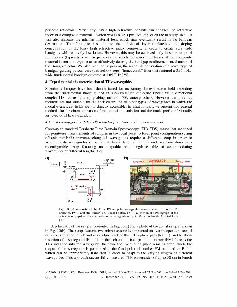
Fig. 10. (a) Schematic of the THz-TDS setup for waveguide measurements: E: Emitter, D:
Detector, PM: Parabolic Mirror, BS: Beam Splitter, FM: Flat Mirror. (b) Photograph of the
actual setup capable of accommodating a waveguide of up to 50 cm in length. Adapted from
[19].
A schematic of the setup is presented in Fig. 10(a) and a photo of the actual setup is shown
in Fig. 10(b). The setup features two mirror assemblies mounted on two independent sets of
rails so as to allow quick and easy adjustment of the THz optical path (Rail 2), and to allow
insertion of a waveguide (Rail 1). In this scheme, a fixed parabolic mirror (PM) focuses the
THz radiation into the waveguide, therefore the in-coupling plane remains fixed; while the
output of the waveguide is positioned at the focal point of another PM mounted on Rail 1
which can be appropriately translated in order to adapt to the varying lengths of different
waveguides. This approach successfully measured THz waveguides of up to 50 cm in length
#155808 - $15.00 USD Received 30 Sep 2011; revised 18 Nov 2011; accepted 22 Nov 2011; published 7 Dec 2011(C) 2011 OSA 12 December 2011 / Vol. 19, No. 26 / OPTICS EXPRESS B859
[19]. We also note that the same setup may be used for pointwise sample measurements by
simply displacing the PM mounted on Rail 1 such that its focal point coincides with that of
the first PM (on the left). From the Fourier transformation of the sampled time-domain signal,
we find that the maximum resolved frequency (max
f ) and the spectral resolution ( df ) of the
acquired data are related to the delay line motor step size ( dx ) and the total delay line
displacement ( x∆ ) through max
(2 )f c dx= and (2 )df c x= ∆ , respectively. Hence, in order
to measure with 0.01 THz resolution a typical THz pulse spectrum that extends from 0 to 3
THz, the corresponding setup requirements are max
5f > THz (thus 30dx < µm) chosen so as
to avoid spectral artifacts, and 15x∆ = mm [31].
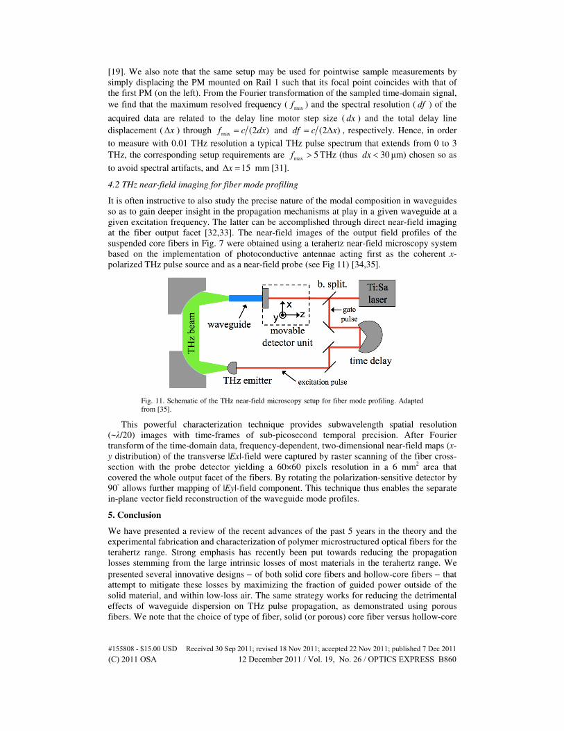
4.2 THz near-field imaging for fiber mode profiling
It is often instructive to also study the precise nature of the modal composition in waveguides
so as to gain deeper insight in the propagation mechanisms at play in a given waveguide at a
given excitation frequency. The latter can be accomplished through direct near-field imaging
at the fiber output facet [32,33]. The near-field images of the output field profiles of the
suspended core fibers in Fig. 7 were obtained using a terahertz near-field microscopy system
based on the implementation of photoconductive antennae acting first as the coherent x-
polarized THz pulse source and as a near-field probe (see Fig 11) [34,35].
Fig. 11. Schematic of the THz near-field microscopy setup for fiber mode profiling. Adapted
from [35].
This powerful characterization technique provides subwavelength spatial resolution
(~λ/20) images with time-frames of sub-picosecond temporal precision. After Fourier
transform of the time-domain data, frequency-dependent, two-dimensional near-field maps (x-
y distribution) of the transverse |Ex|-field were captured by raster scanning of the fiber cross-
section with the probe detector yielding a 60×60 pixels resolution in a 6 mm2 area that
covered the whole output facet of the fibers. By rotating the polarization-sensitive detector by
90◦ allows further mapping of |Ey|-field component. This technique thus enables the separate
in-plane vector field reconstruction of the waveguide mode profiles.
5. Conclusion
We have presented a review of the recent advances of the past 5 years in the theory and the
experimental fabrication and characterization of polymer microstructured optical fibers for the
terahertz range. Strong emphasis has recently been put towards reducing the propagation
losses stemming from the large intrinsic losses of most materials in the terahertz range. We
presented several innovative designs − of both solid core fibers and hollow-core fibers − that
attempt to mitigate these losses by maximizing the fraction of guided power outside of the
solid material, and within low-loss air. The same strategy works for reducing the detrimental
effects of waveguide dispersion on THz pulse propagation, as demonstrated using porous
fibers. We note that the choice of type of fiber, solid (or porous) core fiber versus hollow-core
#155808 - $15.00 USD Received 30 Sep 2011; revised 18 Nov 2011; accepted 22 Nov 2011; published 7 Dec 2011(C) 2011 OSA 12 December 2011 / Vol. 19, No. 26 / OPTICS EXPRESS B860
fiber, depends essentially on the intended user application. For example, if the priority is
beam quality, as in fiber-scanning near-field imaging, then a subwavelength (solid / porous)
core fiber is the most suitable solution because of the single-moded and Gaussian-like mode
profile. However, for efficient THz signal delivery one might prefer hollow-core fibers that
theoretically provide lower losses and lower dispersion capabilities, as well as the possibility
to engineer relatively wide bandgaps at higher frequencies.
Moreover, two relatively recent and complementary techniques for the optical
characterization of THz waveguides were presented. A fast reconfigurable THz-TDS setup
capable of accommodating straight waveguides of up to 50 cm in length, and measuring their
THz transmission, was first described. The use of THz near-field imaging for assessing the
output mode profile of polymer fibers was also discussed.
The recent results show that polymer-based waveguide technology is well suited to tackle
the challenges of THz wave guiding. Towards that end, polymer materials possess several key
incentives: they constitute relatively low-loss THz materials, offer a wide variety of chemical
formulations with different thermo-mechanical properties, are cost-effective and easy to
process, and thus amenable to an industrial-scale deployment of plastic-based THz
waveguides and devices.
Acknowlegment
We acknowledge the contribution of Dr. Markus Walther (Freiburg University) for producing
the near-field data used in Figure 7.
#155808 - $15.00 USD Received 30 Sep 2011; revised 18 Nov 2011; accepted 22 Nov 2011; published 7 Dec 2011(C) 2011 OSA 12 December 2011 / Vol. 19, No. 26 / OPTICS EXPRESS B861
Recommended


![Anthracene Fibers Grown in a Microstructured Optical Fiber ...€¦ · Many experimental techniques have been explored to grow and characterize anthracene crystals [21–24]. Large](https://img.pdfslide.us/doc/110x75/60052648d534fa307c57888b/anthracene-fibers-grown-in-a-microstructured-optical-fiber-many-experimental.jpg)