PLUS
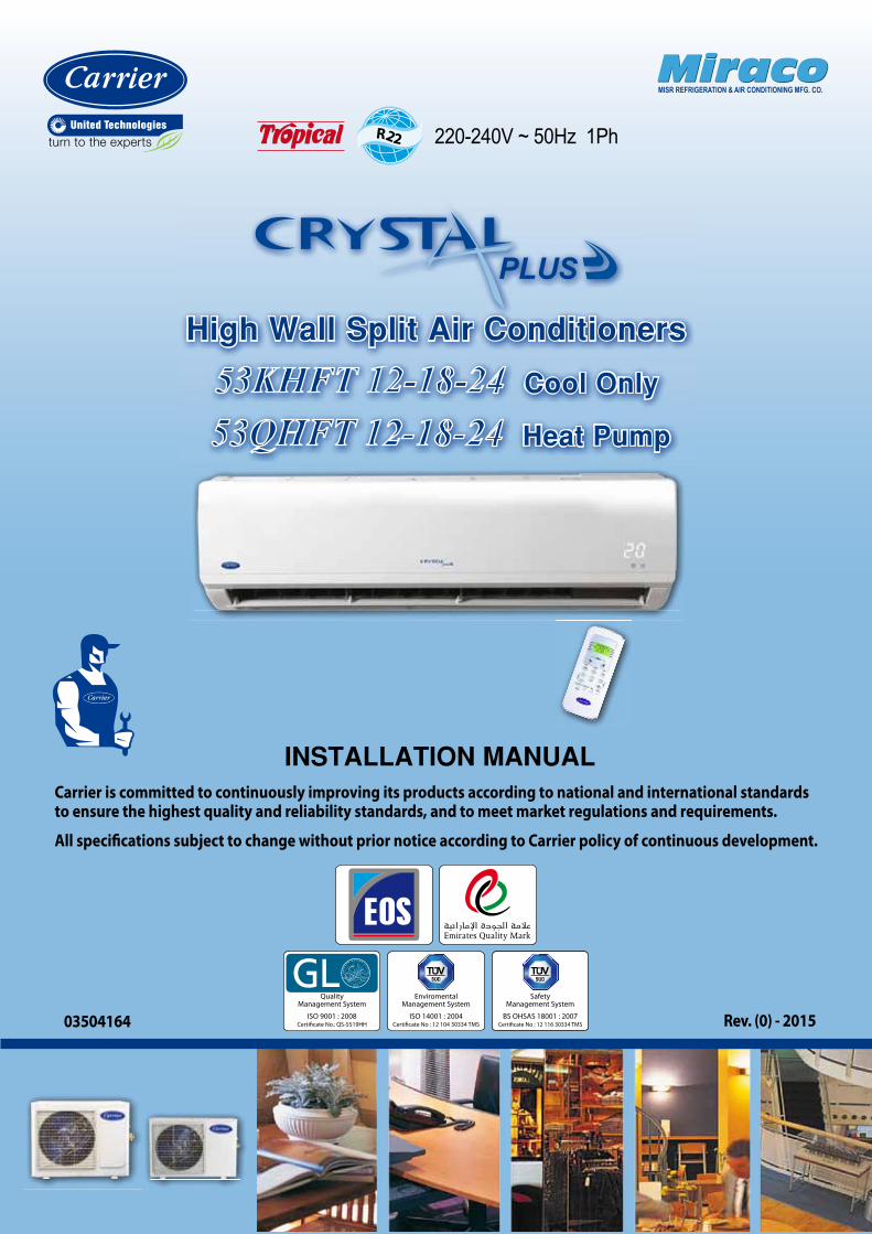
High Wall Split Air Conditioners53KHFT 12-18-24 Cool Only
53QHFT 12-18-24 Heat Pump
Rev. (0) - 2015
R22 220-240V ~ 50Hz 1Ph
MiracoMiracoMISR REFRIGERATION & AIR CONDITIONING MFG. CO.
Enviromental Management System
ISO 14001 : 2004Certificate No : 12 104 30334 TMS
Safety Management System
BS OHSAS 18001 : 2007Certificate No : 12 116 30334 TMS
QualityManagement System
ISO 9001 : 2008Certificate No.: QS-5519HH03504164
Carrier is committed to continuously improving its products according to national and international standards to ensure the highest quality and reliability standards, and to meet market regulations and requirements.
All specifications subject to change without prior notice according to Carrier policy of continuous development.
INSTALLATION MANUAL
Thank you for selecting Carrier
Air Conditioner
High Wall Split is the optimum air conditioning
solution for places which require high wall installation, elegant
appearance and ultimate comfort combined with efficient, quiet
operation, optimum air distribution, and efficient Indoor Air
Quality (IAQ).
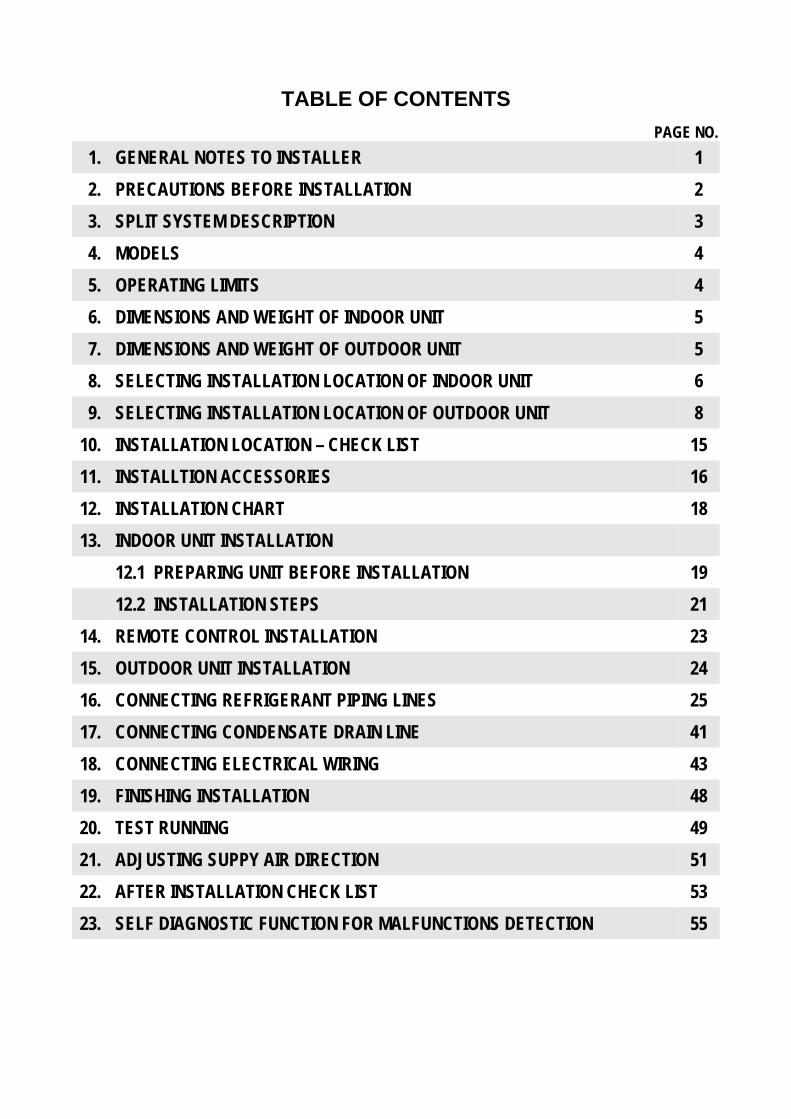
TABLE OF CONTENTS
PAGE NO. 1. GENERAL NOTES TO INSTALLER 1 2. PRECAUTIONS BEFORE INSTALLATION 2 3. SPLIT SYSTEM DESCRIPTION 3 4. MODELS 4 5. OPERATING LIMITS 4 6. DIMENSIONS AND WEIGHT OF INDOOR UNIT 5 7. DIMENSIONS AND WEIGHT OF OUTDOOR UNIT 5 8. SELECTING INSTALLATION LOCATION OF INDOOR UNIT 6 9. SELECTING INSTALLATION LOCATION OF OUTDOOR UNIT 8
10. INSTALLATION LOCATION – CHECK LIST 15 11. INSTALLTION ACCESSORIES 16 12. INSTALLATION CHART 18 13. INDOOR UNIT INSTALLATION
12.1 PREPARING UNIT BEFORE INSTALLATION 19 12.2 INSTALLATION STEPS 21
14. REMOTE CONTROL INSTALLATION 23 15. OUTDOOR UNIT INSTALLATION 24 16. CONNECTING REFRIGERANT PIPING LINES 25 17. CONNECTING CONDENSATE DRAIN LINE 41 18. CONNECTING ELECTRICAL WIRING 43 19. FINISHING INSTALLATION 48 20. TEST RUNNING 49 21. ADJUSTING SUPPY AIR DIRECTION 51 22. AFTER INSTALLATION CHECK LIST 53 23. SELF DIAGNOSTIC FUNCTION FOR MALFUNCTIONS DETECTION 55
1
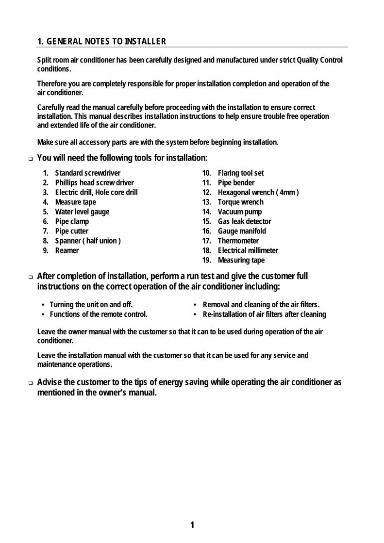
1. GENERAL NOTES TO INSTALLER Split room air conditioner has been carefully designed and manufactured under strict Quality Control conditions. Therefore you are completely responsible for proper installation completion and operation of the air conditioner. Carefully read the manual carefully before proceeding with the installation to ensure correct installation. This manual describes installation instructions to help ensure trouble free operation and extended life of the air conditioner. Make sure all accessory parts are with the system before beginning installation.
You will need the following tools for installation: 1. Standard screwdriver 10. Flaring tool set 2. Phillips head screw driver 11. Pipe bender 3. Electric drill, Hole core drill 12. Hexagonal wrench ( 4mm ) 4. Measure tape 13. Torque wrench 5. Water level gauge 14. Vacuum pump 6. Pipe clamp 15. Gas leak detector 7. Pipe cutter 16. Gauge manifold 8. Spanner ( half union ) 17. Thermometer 9. Reamer 18. Electrical millimeter
19. Measuring tape
After completion of installation, perform a run test and give the customer full instructions on the correct operation of the air conditioner including:
• Turning the unit on and off. • Removal and cleaning of the air filters. • Functions of the remote control. • Re-installation of air filters after cleaning
Leave the owner manual with the customer so that it can to be used during operation of the air conditioner. Leave the installation manual with the customer so that it can be used for any service and maintenance operations.
Advise the customer to the tips of energy saving while operating the air conditioner as mentioned in the owner’s manual.
2
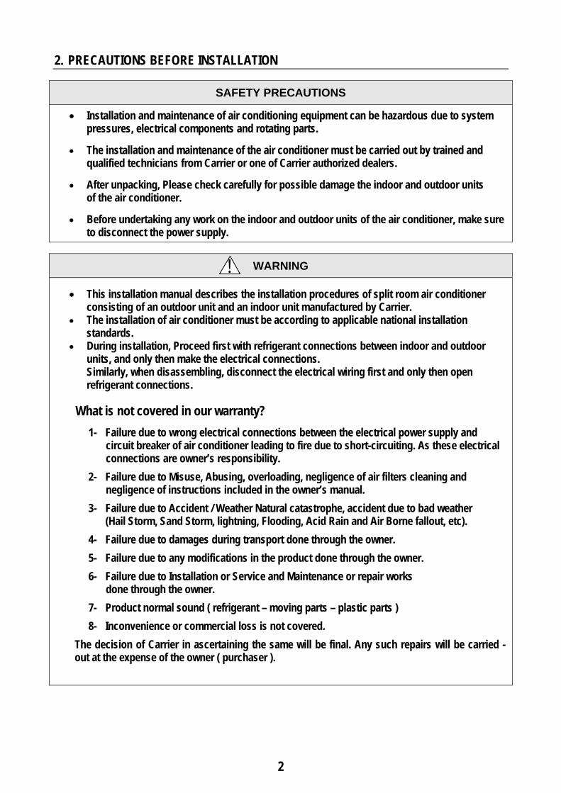
2. PRECAUTIONS BEFORE INSTALLATION
SAFETY PRECAUTIONS
• Installation and maintenance of air conditioning equipment can be hazardous due to system pressures, electrical components and rotating parts.
• The installation and maintenance of the air conditioner must be carried out by trained and
qualified technicians from Carrier or one of Carrier authorized dealers.
• After unpacking, Please check carefully for possible damage the indoor and outdoor units of the air conditioner.
• Before undertaking any work on the indoor and outdoor units of the air conditioner, make sure
to disconnect the power supply.
WARNING • This installation manual describes the installation procedures of split room air conditioner
consisting of an outdoor unit and an indoor unit manufactured by Carrier. • The installation of air conditioner must be according to applicable national installation
standards. • During installation, Proceed first with refrigerant connections between indoor and outdoor
units, and only then make the electrical connections. Similarly, when disassembling, disconnect the electrical wiring first and only then open refrigerant connections.
What is not covered in our warranty?
1- Failure due to wrong electrical connections between the electrical power supply and circuit breaker of air conditioner leading to fire due to short-circuiting. As these electrical connections are owner’s responsibility.
2- Failure due to Misuse, Abusing, overloading, negligence of air filters cleaning and negligence of instructions included in the owner’s manual.
3- Failure due to Accident / Weather Natural catastrophe, accident due to bad weather (Hail Storm, Sand Storm, lightning, Flooding, Acid Rain and Air Borne fallout, etc).
4- Failure due to damages during transport done through the owner.
5- Failure due to any modifications in the product done through the owner.
6- Failure due to Installation or Service and Maintenance or repair works done through the owner.
7- Product normal sound ( refrigerant – moving parts – plastic parts )
8- Inconvenience or commercial loss is not covered.
The decision of Carrier in ascertaining the same will be final. Any such repairs will be carried - out at the expense of the owner ( purchaser ).
!
3
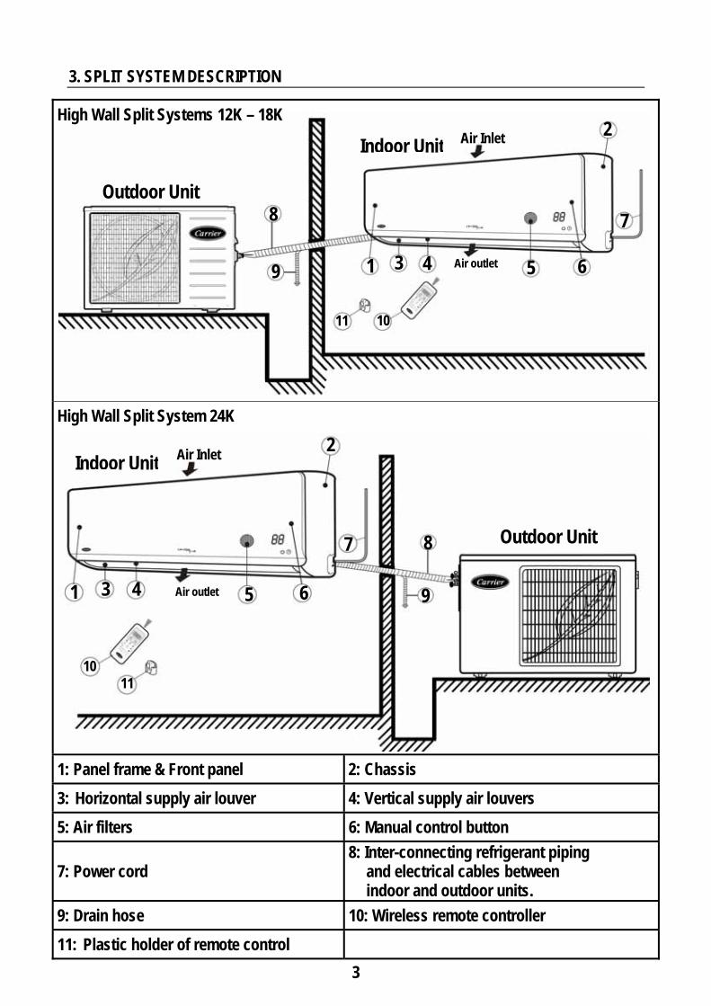
3. SPLIT SYSTEM DESCRIPTION
High Wall Split Systems 12K – 18K
High Wall Split System 24K
1: Panel frame & Front panel 2: Chassis 3: Horizontal supply air louver 4: Vertical supply air louvers 5: Air filters 6: Manual control button
7: Power cord 8: Inter-connecting refrigerant piping
and electrical cables between indoor and outdoor units.
9: Drain hose 10: Wireless remote controller 11: Plastic holder of remote control
Indoor Unit Air Inlet
1 3
5
11
Air outlet
6
2
Outdoor Unit
Outdoor Unit
5 6
10
Air Inlet 2
1 3 Air outlet
Indoor Unit
10
11
4
7 8
9
4
7 8
9
4
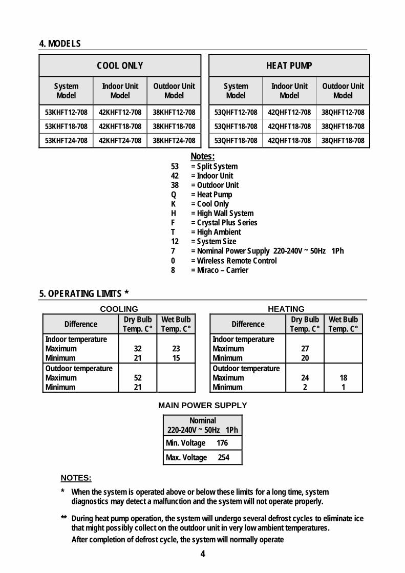
4. MODELS
COOL ONLY HEAT PUMP
System Model
Indoor Unit Model
Outdoor Unit Model
System Model
Indoor Unit Model
Outdoor Unit Model
53KHFT12-708 42KHFT12-708 38KHFT12-708 53QHFT12-708 42QHFT12-708 38QHFT12-708
53KHFT18-708 42KHFT18-708 38KHFT18-708 53QHFT18-708 42QHFT18-708 38QHFT18-708
53KHFT24-708 42KHFT24-708 38KHFT24-708 53QHFT18-708 42QHFT18-708 38QHFT18-708
Notes: 53 = Split System 42 = Indoor Unit 38 = Outdoor Unit Q = Heat Pump K = Cool Only H = High Wall System F = Crystal Plus Series T = High Ambient 12 = System Size 7 = Nominal Power Supply 220-240V ~ 50Hz 1Ph 0 = Wireless Remote Control 8 = Miraco – Carrier
5. OPERATING LIMITS *
COOLING HEATING
Difference Dry Bulb Temp. C°
Wet Bulb Temp. C° Difference Dry Bulb
Temp. C° Wet Bulb Temp. C°
Indoor temperature Maximum Minimum
32 21
23 15
Indoor temperature Maximum Minimum
27 20
Outdoor temperature Maximum Minimum
52 21
Outdoor temperature Maximum Minimum
24 2
18 1
MAIN POWER SUPPLY
Nominal 220-240V ~ 50Hz 1Ph Min. Voltage 176
Max. Voltage 254
NOTES: * When the system is operated above or below these limits for a long time, system
diagnostics may detect a malfunction and the system will not operate properly. ** During heat pump operation, the system will undergo several defrost cycles to eliminate ice
that might possibly collect on the outdoor unit in very low ambient temperatures.
After completion of defrost cycle, the system will normally operate
5
860
665
350
384
575
371
350
665
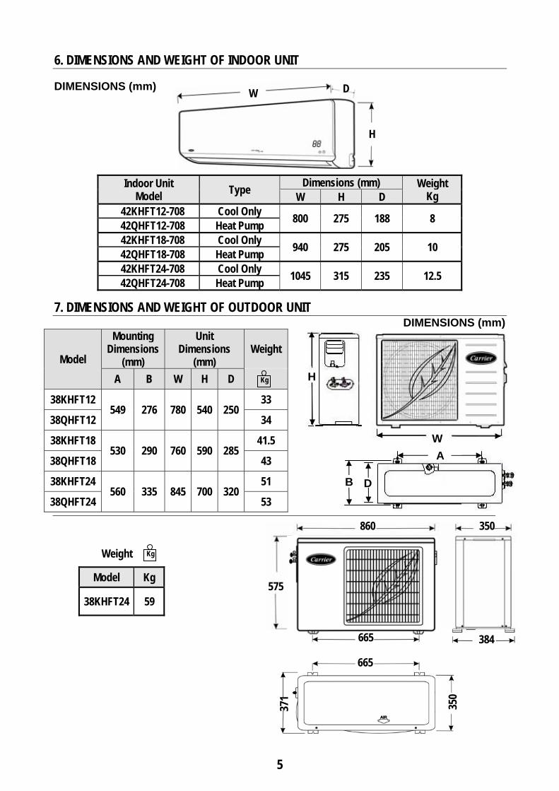
6. DIMENSIONS AND WEIGHT OF INDOOR UNIT DIMENSIONS (mm)
Indoor Unit Model Type Dimensions (mm) Weight
Kg W H D 42KHFT12-708 Cool Only 800 275 188 8 42QHFT12-708 Heat Pump 42KHFT18-708 Cool Only 940 275 205 10 42QHFT18-708 Heat Pump 42KHFT24-708 Cool Only 1045 315 235 12.5 42QHFT24-708 Heat Pump
7. DIMENSIONS AND WEIGHT OF OUTDOOR UNIT DIMENSIONS (mm)
Model
Mounting Dimensions
(mm)
Unit Dimensions
(mm)
Weight
A B W H D
38KHFT12 549 276 780 540 250
33
38QHFT12 34
38KHFT18 530 290 760 590 285
41.5
38QHFT18 43
38KHFT24 560 335 845 700 320
51
38QHFT24 53
Weight
Model Kg
38KHFT24 59
W D
H
Kg
W
H
D
A
B
Kg
6
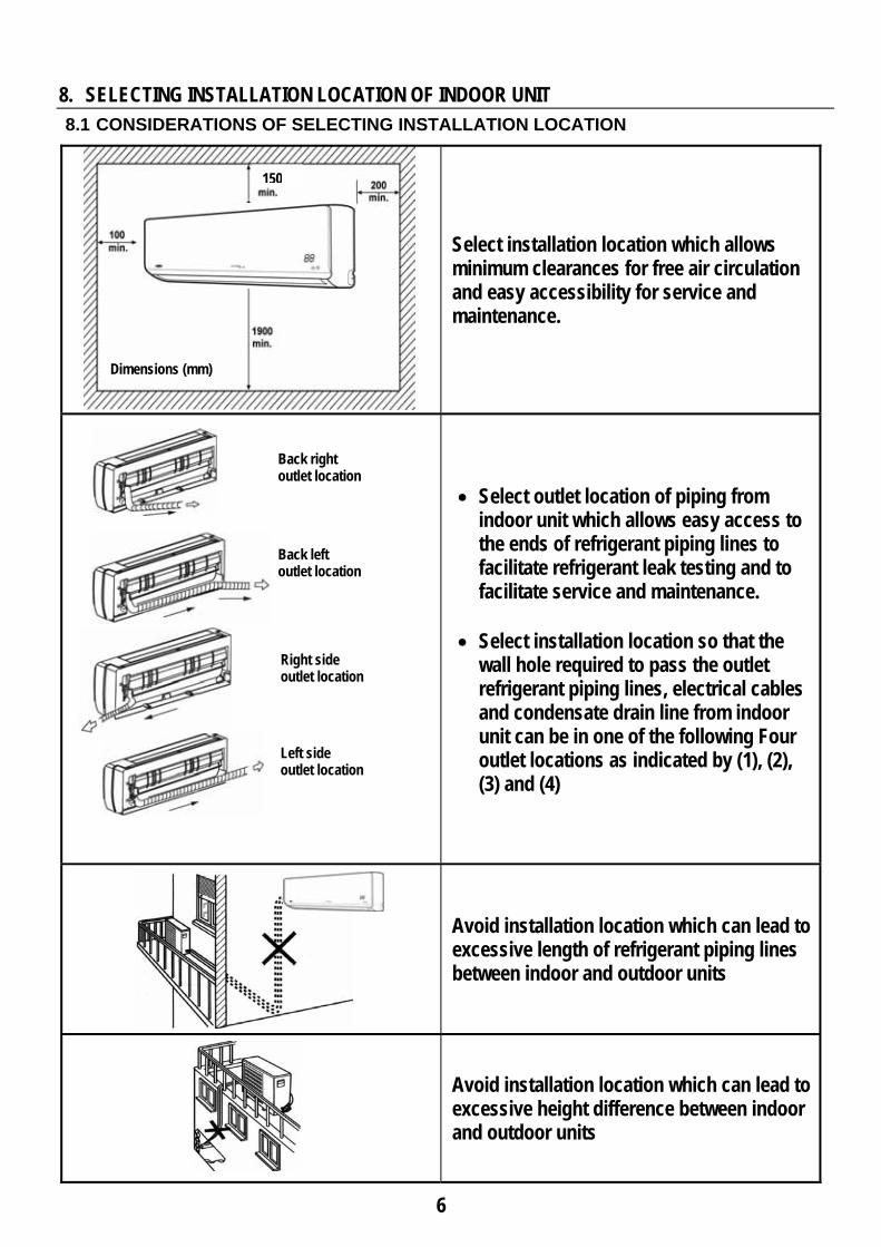
8. SELECTING INSTALLATION LOCATION OF INDOOR UNIT
8.1 CONSIDERATIONS OF SELECTING INSTALLATION LOCATION
Select installation location which allows minimum clearances for free air circulation and easy accessibility for service and maintenance.
• Select outlet location of piping from indoor unit which allows easy access to the ends of refrigerant piping lines to facilitate refrigerant leak testing and to facilitate service and maintenance.
• Select installation location so that the
wall hole required to pass the outlet refrigerant piping lines, electrical cables and condensate drain line from indoor unit can be in one of the following Four outlet locations as indicated by (1), (2), (3) and (4)
Avoid installation location which can lead to excessive length of refrigerant piping lines between indoor and outdoor units
Avoid installation location which can lead to excessive height difference between indoor and outdoor units
Dimensions (mm)
Back right outlet location
Back left outlet location
Right side outlet location
Left side outlet location
150
7
SELECTING INSTALLATION LOCATION OF INDOOR UNIT (Cont.)
CONSIDERATIONS OF SELECTING INSTALLATION LOCATION (Cont.)
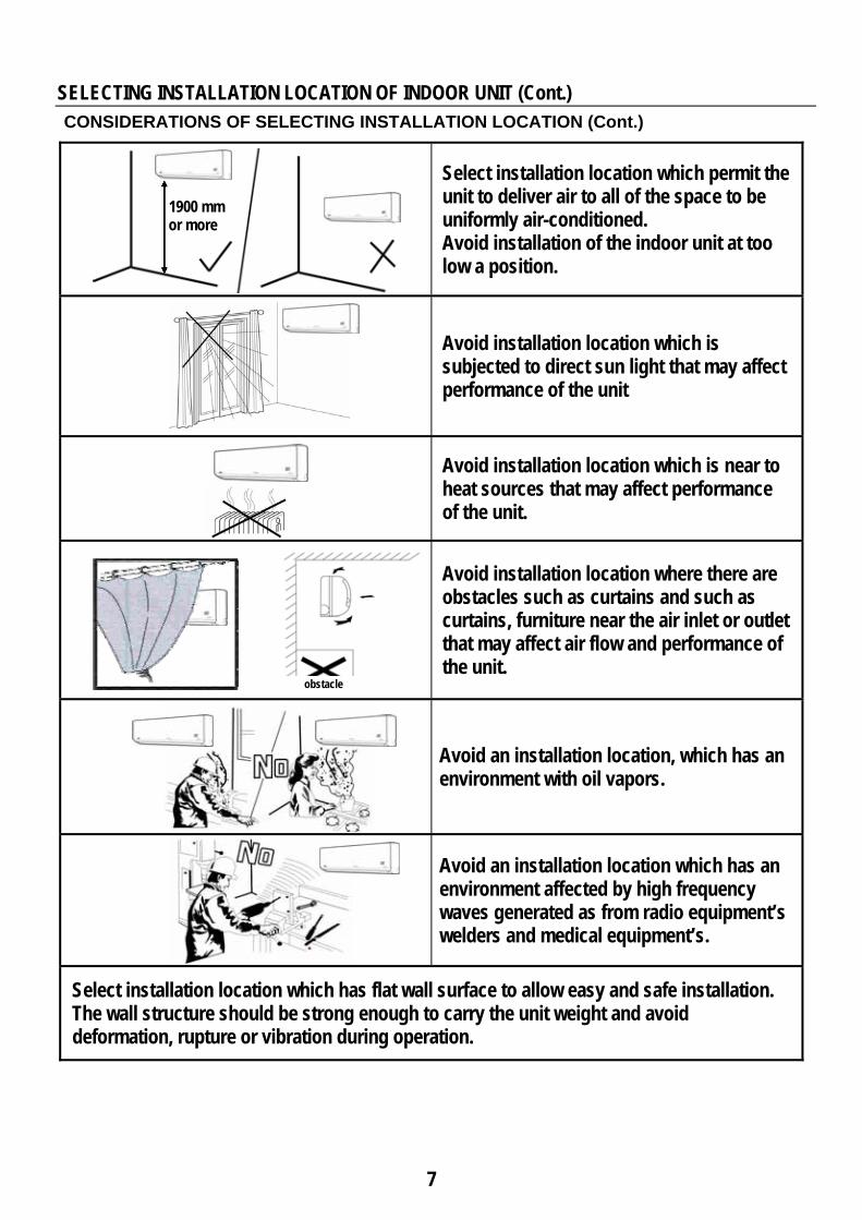
Select installation location which permit the unit to deliver air to all of the space to be uniformly air-conditioned. Avoid installation of the indoor unit at too low a position.
Avoid installation location which is subjected to direct sun light that may affect performance of the unit
Avoid installation location which is near to heat sources that may affect performance of the unit.
Avoid installation location where there are obstacles such as curtains and such as curtains, furniture near the air inlet or outlet that may affect air flow and performance of the unit.
Avoid an installation location, which has an environment with oil vapors.
Avoid an installation location which has an environment affected by high frequency waves generated as from radio equipment’s welders and medical equipment’s.
Select installation location which has flat wall surface to allow easy and safe installation. The wall structure should be strong enough to carry the unit weight and avoid deformation, rupture or vibration during operation.
1900 mm or more
obstacle
8
9. SELECTING INSTALLATION LOCATION OF OUTOOR UNIT 9.1 INSTALLATION LOCATIONS
The outdoor unit can be installed in any outside location, on a wall, on a roof or on a ground level.
9.2 CONSIDERATIONS FOR SELECTING INSTALLATION LOCATIONS
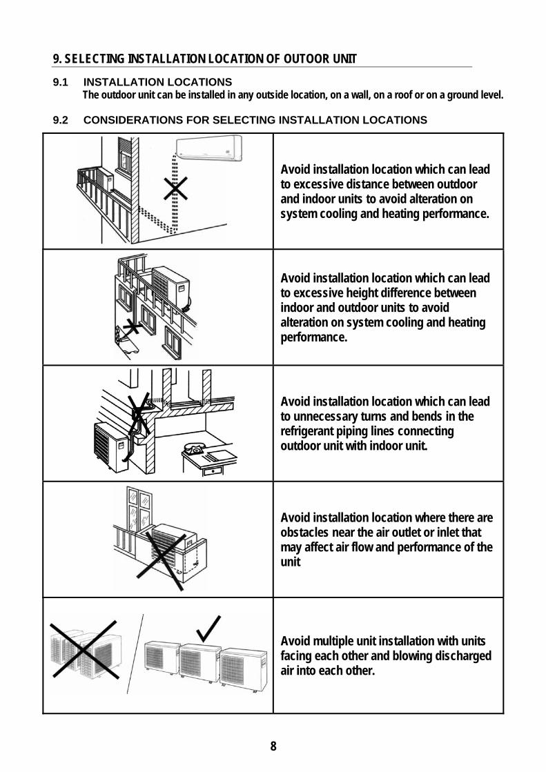
Avoid installation location which can lead to excessive distance between outdoor and indoor units to avoid alteration on system cooling and heating performance.
Avoid installation location which can lead to excessive height difference between indoor and outdoor units to avoid alteration on system cooling and heating performance.
Avoid installation location which can lead to unnecessary turns and bends in the refrigerant piping lines connecting outdoor unit with indoor unit.
Avoid installation location where there are obstacles near the air outlet or inlet that may affect air flow and performance of the unit
Avoid multiple unit installation with units facing each other and blowing discharged air into each other.
9
SELECTING INSTALLATION LOCATION OF OUTOOR UNIT (Cont.)
CONSIDERATIONS FOR SELECTING INSTALLATION LOCATION (Cont.)
Select the installation location of outdoor unit which is able to support operating weight of outdoor unit, and not cause vibration.
Select the installation location of outdoor unit which is far away from the direct sunlight.
Select the installation location of outdoor unit which is far away from heat sources, steam or flammable gas.
Select the installation location of outdoor unit which is free of dust or any material, which can cause clogging of condenser coil. When installing unit on the ground, select a location not subjected to flooding.
Avoid installation location which is full of oil vapors which may result in malfunction.
Avoid installation location which is full of sulfuric gas which may result in malfunction.
Select installation location where the operation noise and discharged air are not disruptive to your neighbors.
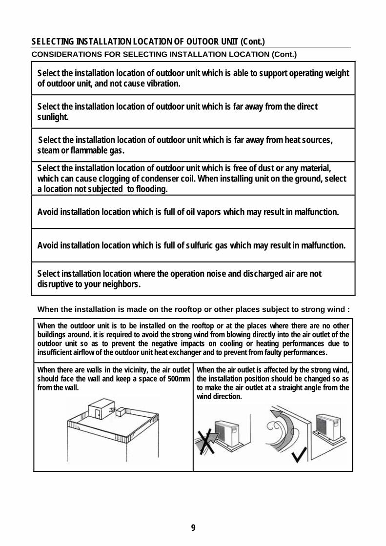
When the installation is made on the rooftop or other places subject to strong wind :
When the outdoor unit is to be installed on the rooftop or at the places where there are no other buildings around. it is required to avoid the strong wind from blowing directly into the air outlet of the outdoor unit so as to prevent the negative impacts on cooling or heating performances due to insufficient airflow of the outdoor unit heat exchanger and to prevent from faulty performances.
When there are walls in the vicinity, the air outlet should face the wall and keep a space of 500mm from the wall.
When the air outlet is affected by the strong wind, the installation position should be changed so as to make the air outlet at a straight angle from the wind direction.
10
SELECTING INSTALLATION LOCATION OF OUTOOR UNIT (Cont.)
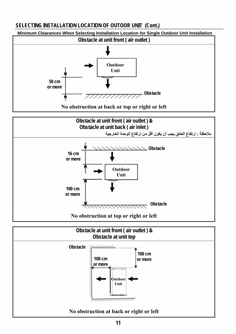
9.3 Minimum Clearances When Selecting Installation Location for Single Outdoor Unit Installation Minimum Clearances When Selecting Installation Location for Serial Installation of More Than One Outdoor Unit
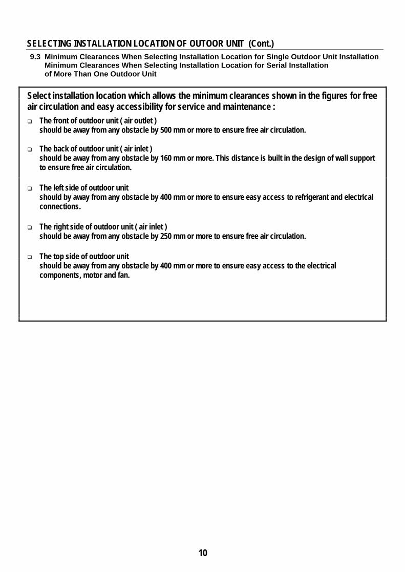
Select installation location which allows the minimum clearances shown in the figures for free air circulation and easy accessibility for service and maintenance :
The front of outdoor unit ( air outlet ) should be away from any obstacle by 500 mm or more to ensure free air circulation.
The back of outdoor unit ( air inlet )
should be away from any obstacle by 160 mm or more. This distance is built in the design of wall support to ensure free air circulation.
The left side of outdoor unit
should by away from any obstacle by 400 mm or more to ensure easy access to refrigerant and electrical connections.
The right side of outdoor unit ( air inlet )
should be away from any obstacle by 250 mm or more to ensure free air circulation.
The top side of outdoor unit should be away from any obstacle by 400 mm or more to ensure easy access to the electrical components, motor and fan.
11
SELECTING INSTALLATION LOCATION OF OUTOOR UNIT (Cont.)
Minimum Clearances When Selecting Installation Location for Single Outdoor Unit Installation Obstacle at unit front ( air outlet )
No obstruction at back or top or right or left
Obstacle at unit front ( air outlet ) & Obstacle at unit back ( air inlet )
الوحدة الخارجية اعإرتفاع العائق يجب أن يكون أقل من إرتف: مالحظة
No obstruction at top or right or left
Obstacle at unit front ( air outlet ) & Obstacle at unit top
No obstruction at back or right or left
100 cm or more
16 cm or more
50 cm or more
Outdoor Unit
Obstacle
Outdoor Unit
Obstacle
Obstacle
100 cm or more
100 cm or more
Obstacle
Outdoor Unit
12
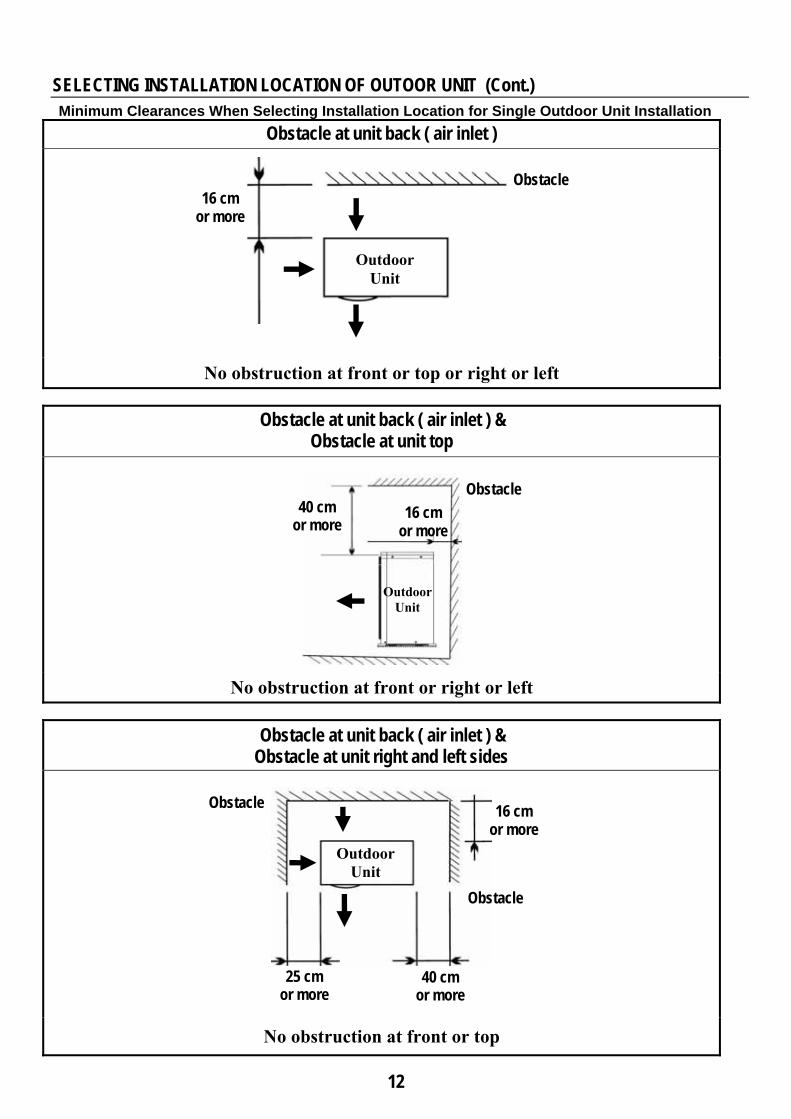
SELECTING INSTALLATION LOCATION OF OUTOOR UNIT (Cont.)
Minimum Clearances When Selecting Installation Location for Single Outdoor Unit Installation Obstacle at unit back ( air inlet )
No obstruction at front or top or right or left
Obstacle at unit back ( air inlet ) & Obstacle at unit top
No obstruction at front or right or left
Obstacle at unit back ( air inlet ) & Obstacle at unit right and left sides
No obstruction at front or top
16 cm or more
Outdoor Unit
Obstacle
16 cm or more
Obstacle
40 cm or more
25 cm or more
Obstacle
16 cm or more
Outdoor Unit
Obstacle 40 cm
or more
Outdoor Unit
13
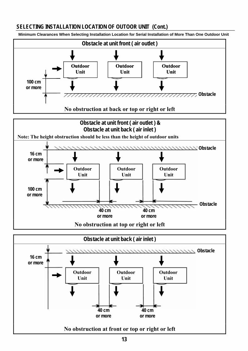
SELECTING INSTALLATION LOCATION OF OUTOOR UNIT (Cont.)
Minimum Clearances When Selecting Installation Location for Serial Installation of More Than One Outdoor Unit
Obstacle at unit front ( air outlet )
No obstruction at back or top or right or left
Obstacle at unit front ( air outlet ) & Obstacle at unit back ( air inlet )
Note: The height obstruction should be less than the height of outdoor units
No obstruction at top or right or left
Obstacle at unit back ( air inlet )
No obstruction at front or top or right or left
100 cm or more
16 cm or more
40 cm or more
100 cm or more
Outdoor Unit
Obstacle
Obstacle
Obstacle
16 cm or more
Obstacle
Outdoor Unit
Outdoor Unit
Outdoor Unit
Outdoor Unit
Outdoor Unit
Outdoor Unit
Outdoor Unit
Outdoor Unit
40 cm or more
Outdoor Unit
Outdoor Unit
Outdoor Unit
40 cm or more
40 cm or more
14
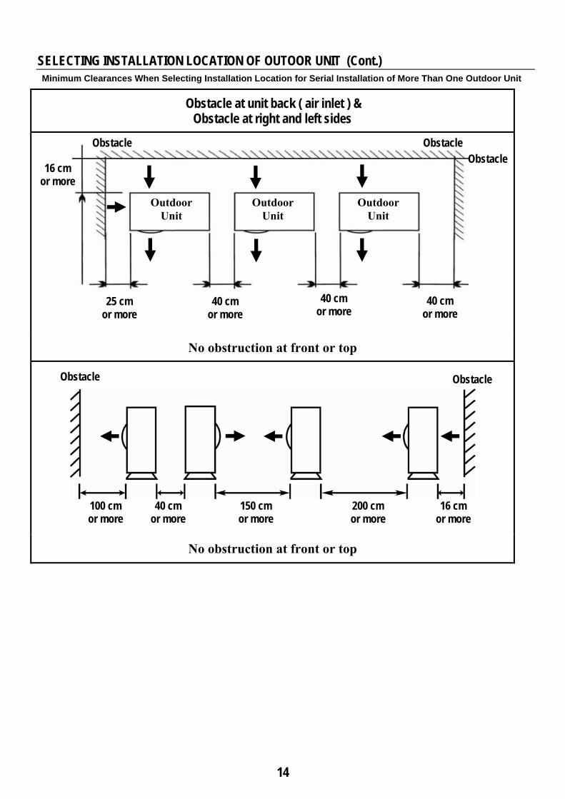
SELECTING INSTALLATION LOCATION OF OUTOOR UNIT (Cont.)
Minimum Clearances When Selecting Installation Location for Serial Installation of More Than One Outdoor Unit
Obstacle at unit back ( air inlet ) & Obstacle at right and left sides
No obstruction at front or top
No obstruction at front or top
16 cm or more
Obstacle
100 cm or more
40 cm or more
200 cm or more
150 cm or more
16 cm or more
40 cm or more
40 cm or more
Obstacle
40 cm or more
25 cm or more
Obstacle Obstacle
Obstacle
Outdoor Unit
Outdoor Unit
Outdoor Unit
15
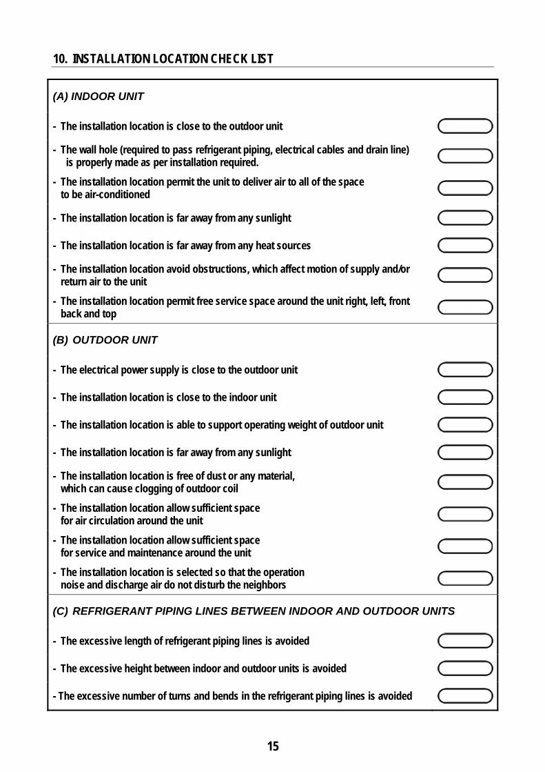
10. INSTALLATION LOCATION CHECK LIST
(A) INDOOR UNIT
- The installation location is close to the outdoor unit
- The wall hole (required to pass refrigerant piping, electrical cables and drain line) is properly made as per installation required.
- The installation location permit the unit to deliver air to all of the space to be air-conditioned
- The installation location is far away from any sunlight
- The installation location is far away from any heat sources
- The installation location avoid obstructions, which affect motion of supply and/or return air to the unit
- The installation location permit free service space around the unit right, left, front back and top
(B) OUTDOOR UNIT
- The electrical power supply is close to the outdoor unit
- The installation location is close to the indoor unit
- The installation location is able to support operating weight of outdoor unit
- The installation location is far away from any sunlight
- The installation location is free of dust or any material, which can cause clogging of outdoor coil
- The installation location allow sufficient space for air circulation around the unit
- The installation location allow sufficient space for service and maintenance around the unit
- The installation location is selected so that the operation noise and discharge air do not disturb the neighbors
(C) REFRIGERANT PIPING LINES BETWEEN INDOOR AND OUTDOOR UNITS
- The excessive length of refrigerant piping lines is avoided
- The excessive height between indoor and outdoor units is avoided
- The excessive number of turns and bends in the refrigerant piping lines is avoided
16
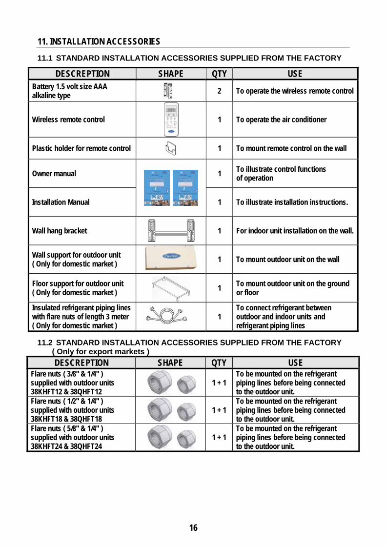
11. INSTALLATION ACCESSORIES 11.1 STANDARD INSTALLATION ACCESSORIES SUPPLIED FROM THE FACTORY
DESCREPTION SHAPE QTY USE Battery 1.5 volt size AAA alkaline type
2 To operate the wireless remote control
Wireless remote control
1 To operate the air conditioner
Plastic holder for remote control
1 To mount remote control on the wall
Owner manual
1 To illustrate control functions of operation
Installation Manual 1 To illustrate installation instructions.
Wall hang bracket
1 For indoor unit installation on the wall.
Wall support for outdoor unit ( Only for domestic market )
1 To mount outdoor unit on the wall
Floor support for outdoor unit ( Only for domestic market )
1 To mount outdoor unit on the ground
or floor
Insulated refrigerant piping lines with flare nuts of length 3 meter ( Only for domestic market )
1
To connect refrigerant between outdoor and indoor units and refrigerant piping lines
11.2 STANDARD INSTALLATION ACCESSORIES SUPPLIED FROM THE FACTORY
( Only for export markets ) DESCREPTION SHAPE QTY USE
Flare nuts ( 3/8" & 1/4" ) supplied with outdoor units 38KHFT12 & 38QHFT12
1 + 1
To be mounted on the refrigerant piping lines before being connected to the outdoor unit.
Flare nuts ( 1/2" & 1/4" ) supplied with outdoor units 38KHFT18 & 38QHFT18
1 + 1
To be mounted on the refrigerant piping lines before being connected to the outdoor unit.
Flare nuts ( 5/8" & 1/4" ) supplied with outdoor units 38KHFT24 & 38QHFT24
1 + 1
To be mounted on the refrigerant piping lines before being connected to the outdoor unit.
17
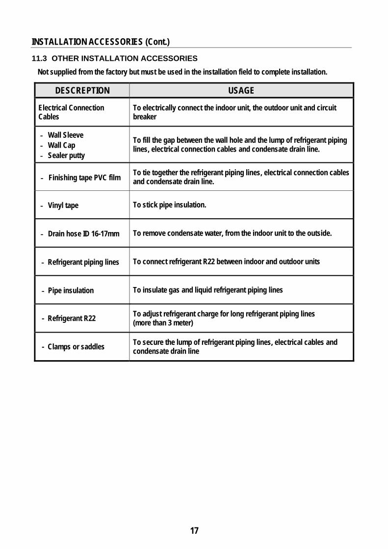
INSTALLATION ACCESSORIES (Cont.) 11.3 OTHER INSTALLATION ACCESSORIES
Not supplied from the factory but must be used in the installation field to complete installation.
DESCREPTION USAGE
Electrical Connection Cables
To electrically connect the indoor unit, the outdoor unit and circuit breaker
Wall Sleeve ـ Wall Cap ـ Sealer putty ـ
To fill the gap between the wall hole and the lump of refrigerant piping lines, electrical connection cables and condensate drain line.
Finishing tape PVC film To tie together the refrigerant piping lines, electrical connection cables ـand condensate drain line.
.Vinyl tape To stick pipe insulation ـ
.Drain hose ID 16-17mm To remove condensate water, from the indoor unit to the outside ـ
Refrigerant piping lines To connect refrigerant R22 between indoor and outdoor units ـ
Pipe insulation To insulate gas and liquid refrigerant piping lines ـ
- Refrigerant R22 To adjust refrigerant charge for long refrigerant piping lines (more than 3 meter)
- Clamps or saddles To secure the lump of refrigerant piping lines, electrical cables and condensate drain line
18
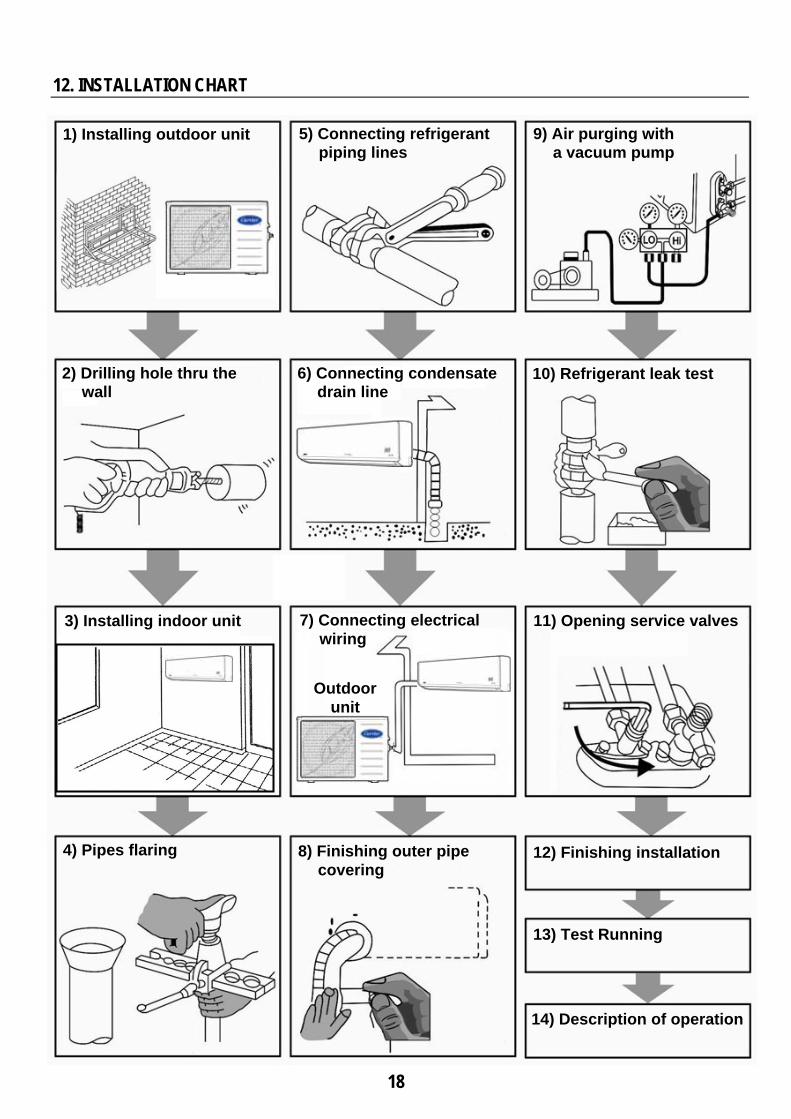
12. INSTALLATION CHART
1) Installing outdoor unit 5) Connecting refrigerant piping lines
9) Air purging with a vacuum pump
2) Drilling hole thru the wall
6) Connecting condensate drain line
10) Refrigerant leak test
3) Installing indoor unit 7) Connecting electrical wiring
11) Opening service valves
4) Pipes flaring 8) Finishing outer pipe covering
12) Finishing installation
13) Test Running
14) Description of operation
Outdoor unit
19
13. INDOOR UNIT INSTALLATION
13-1 PREPARATION STEPS BEFORE INSTALLATION
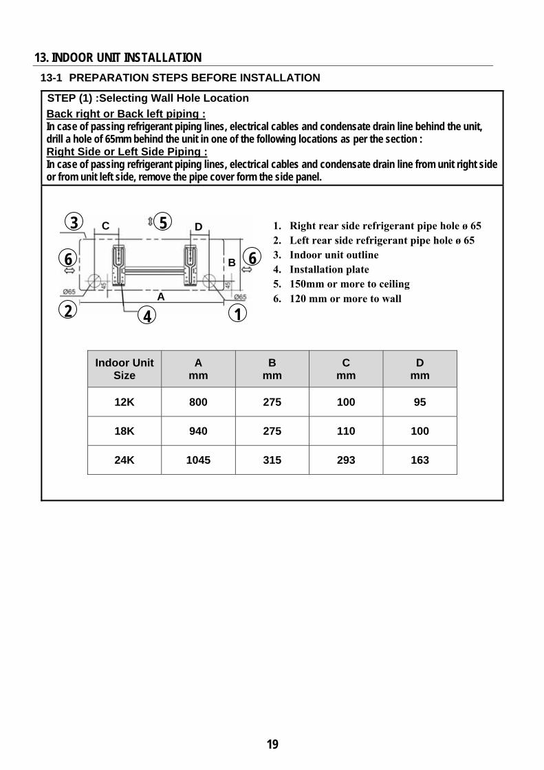
STEP (1) :Selecting Wall Hole Location
Back right or Back left piping : In case of passing refrigerant piping lines, electrical cables and condensate drain line behind the unit, drill a hole of 65mm behind the unit in one of the following locations as per the section : Right Side or Left Side Piping : In case of passing refrigerant piping lines, electrical cables and condensate drain line from unit right side or from unit left side, remove the pipe cover form the side panel.
Indoor Unit Size
A mm
B mm
C mm
D mm
12K 800 275 100 95
18K 940 275 110 100
24K 1045 315 293 163
4
6
5 3
6
2 1
C D
B
A
1. Right rear side refrigerant pipe hole ø 65 2. Left rear side refrigerant pipe hole ø 65 3. Indoor unit outline 4. Installation plate 5. 150mm or more to ceiling 6. 120 mm or more to wall
20
INDOOR UNIT INSTALLATION (Cont.)
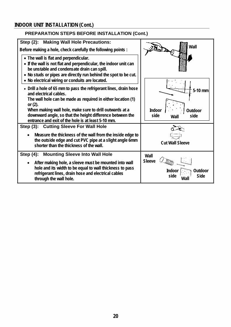
PREPARATION STEPS BEFORE INSTALLATION (Cont.) Step (2): Making Wall Hole Precautions:
Before making a hole, check carefully the following points :
• The wall is flat and perpendicular. • If the wall is not flat and perpendicular, the indoor unit can
be unstable and condensate drain can spill. • No studs or pipes are directly run behind the spot to be cut. • No electrical wiring or conduits are located. • Drill a hole of 65 mm to pass the refrigerant lines, drain hose
and electrical cables. The wall hole can be made as required in either location (1) or (2). When making wall hole, make sure to drill outwards at a downward angle, so that the height difference between the entrance and exit of the hole is at least 5-10 mm.
Step (3): Cutting Sleeve For Wall Hole
• Measure the thickness of the wall from the inside edge to the outside edge and cut PVC pipe at a slight angle 6mm shorter than the thickness of the wall.
Step (4): Mounting Sleeve Into Wall Hole
• After making hole, a sleeve must be mounted into wall hole and its width to be equal to wall thickness to pass refrigerant lines, drain hose and electrical cables through the wall hole.
Wall
5-10 mm
Wall Indoor side
Outdoor side
Cut Wall Sleeve
Indoor side
Outdoor Side
Wall Sleeve
Wall
21
INDOOR UNIT INSTALLATION (Cont.)
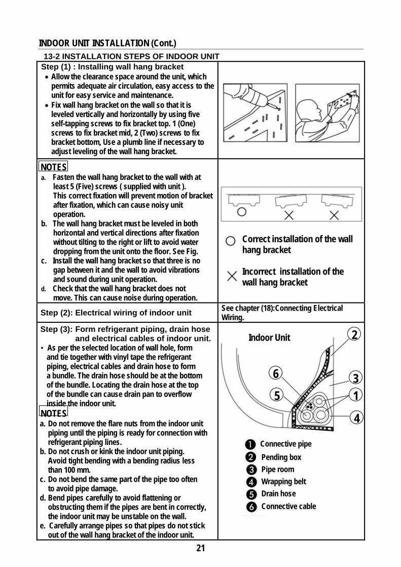
13-2 INSTALLATION STEPS OF INDOOR UNIT Step (1) : Installing wall hang bracket
• Allow the clearance space around the unit, which permits adequate air circulation, easy access to the unit for easy service and maintenance.
• Fix wall hang bracket on the wall so that it is leveled vertically and horizontally by using five self-tapping screws to fix bracket top. 1 (One) screws to fix bracket mid, 2 (Two) screws to fix bracket bottom, Use a plumb line if necessary to adjust leveling of the wall hang bracket.
Correct installation of the wall hang bracket Incorrect installation of the wall hang bracket
NOTES a. Fasten the wall hang bracket to the wall with at
least 5 (Five) screws ( supplied with unit ). This correct fixation will prevent motion of bracket after fixation, which can cause noisy unit operation.
b. The wall hang bracket must be leveled in both horizontal and vertical directions after fixation without tilting to the right or lift to avoid water dropping from the unit onto the floor. See Fig.
c. Install the wall hang bracket so that three is no gap between it and the wall to avoid vibrations and sound during unit operation.
d. Check that the wall hang bracket does not move. This can cause noise during operation.
See chapter (18):Connecting Electrical Wiring.Step (2): Electrical wiring of indoor unit
Step (3): Form refrigerant piping, drain hose and electrical cables of indoor unit.
• As per the selected location of wall hole, form and tie together with vinyl tape the refrigerant piping, electrical cables and drain hose to form a bundle. The drain hose should be at the bottom of the bundle. Locating the drain hose at the top of the bundle can cause drain pan to overflow inside the indoor unit.
NOTES a. Do not remove the flare nuts from the indoor unit
piping until the piping is ready for connection with refrigerant piping lines.
b. Do not crush or kink the indoor unit piping. Avoid tight bending with a bending radius less than 100 mm.
c. Do not bend the same part of the pipe too often to avoid pipe damage.
d. Bend pipes carefully to avoid flattening or obstructing them if the pipes are bent in correctly, the indoor unit may be unstable on the wall.
e. Carefully arrange pipes so that pipes do not stick out of the wall hang bracket of the indoor unit.
Connective pipe
Pending box
Pipe room
Wrapping belt Drain hose
Connective cable
2
3 1
4
5
6
Indoor Unit
22
INSTALLATION OF INDOOR UNIT (Cont.)
INSTALLATION STEPS OF INDOOR UNIT (Cont.)
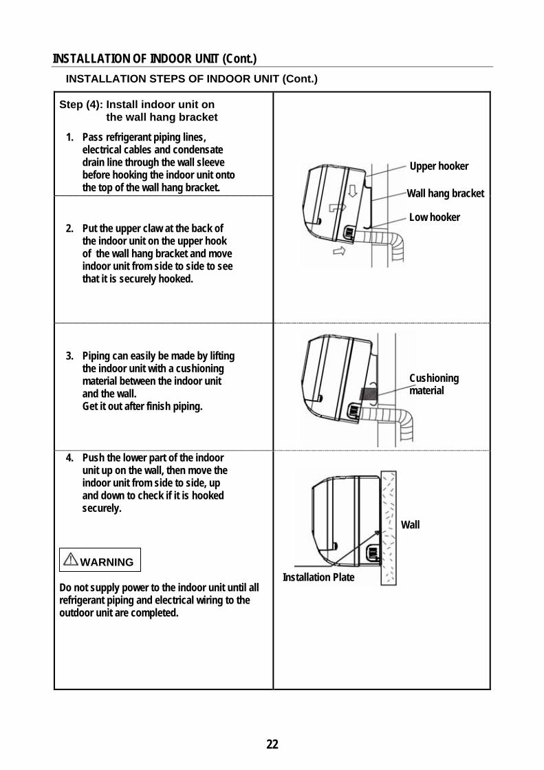
Step (4): Install indoor unit on the wall hang bracket
1. Pass refrigerant piping lines, electrical cables and condensate drain line through the wall sleeve before hooking the indoor unit onto the top of the wall hang bracket.
2. Put the upper claw at the back of the indoor unit on the upper hook of the wall hang bracket and move indoor unit from side to side to see that it is securely hooked.
3. Piping can easily be made by lifting the indoor unit with a cushioning material between the indoor unit and the wall. Get it out after finish piping.
4. Push the lower part of the indoor unit up on the wall, then move the indoor unit from side to side, up and down to check if it is hooked securely.
WARNING
Do not supply power to the indoor unit until all refrigerant piping and electrical wiring to the outdoor unit are completed.
Upper hooker
Low hooker
Cushioning material
Wall hang bracket
Installation Plate
Wall
23
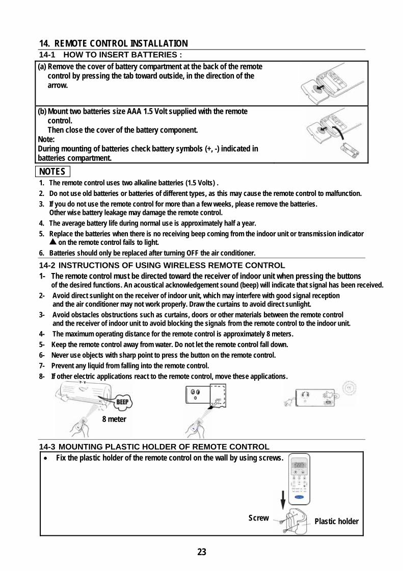
14. REMOTE CONTROL INSTALLATION 14-1 HOW TO INSERT BATTERIES : (a) Remove the cover of battery compartment at the back of the remote
control by pressing the tab toward outside, in the direction of the arrow.
(b) Mount two batteries size AAA 1.5 Volt supplied with the remote
control. Then close the cover of the battery component.
Note: During mounting of batteries check battery symbols (+, -) indicated in batteries compartment.
NOTES 1. The remote control uses two alkaline batteries (1.5 Volts) . 2. Do not use old batteries or batteries of different types, as this may cause the remote control to malfunction. 3. If you do not use the remote control for more than a few weeks, please remove the batteries.
Other wise battery leakage may damage the remote control. 4. The average battery life during normal use is approximately half a year. 5. Replace the batteries when there is no receiving beep coming from the indoor unit or transmission indicator
on the remote control fails to light. 6. Batteries should only be replaced after turning OFF the air conditioner.
14-2 INSTRUCTIONS OF USING WIRELESS REMOTE CONTROL 1- The remote control must be directed toward the receiver of indoor unit when pressing the buttons
of the desired functions. An acoustical acknowledgement sound (beep) will indicate that signal has been received. 2- Avoid direct sunlight on the receiver of indoor unit, which may interfere with good signal reception
and the air conditioner may not work properly. Draw the curtains to avoid direct sunlight. 3- Avoid obstacles obstructions such as curtains, doors or other materials between the remote control
and the receiver of indoor unit to avoid blocking the signals from the remote control to the indoor unit. 4- The maximum operating distance for the remote control is approximately 8 meters. 5- Keep the remote control away from water. Do not let the remote control fall down. 6- Never use objects with sharp point to press the button on the remote control. 7- Prevent any liquid from falling into the remote control. 8- If other electric applications react to the remote control, move these applications.
14-3 MOUNTING PLASTIC HOLDER OF REMOTE CONTROL • Fix the plastic holder of the remote control on the wall by using screws.
Plastic holder Screw
8 meter
24
2
4 1
3
4 Final Assembly of wall support
2
4
1
3
4
A
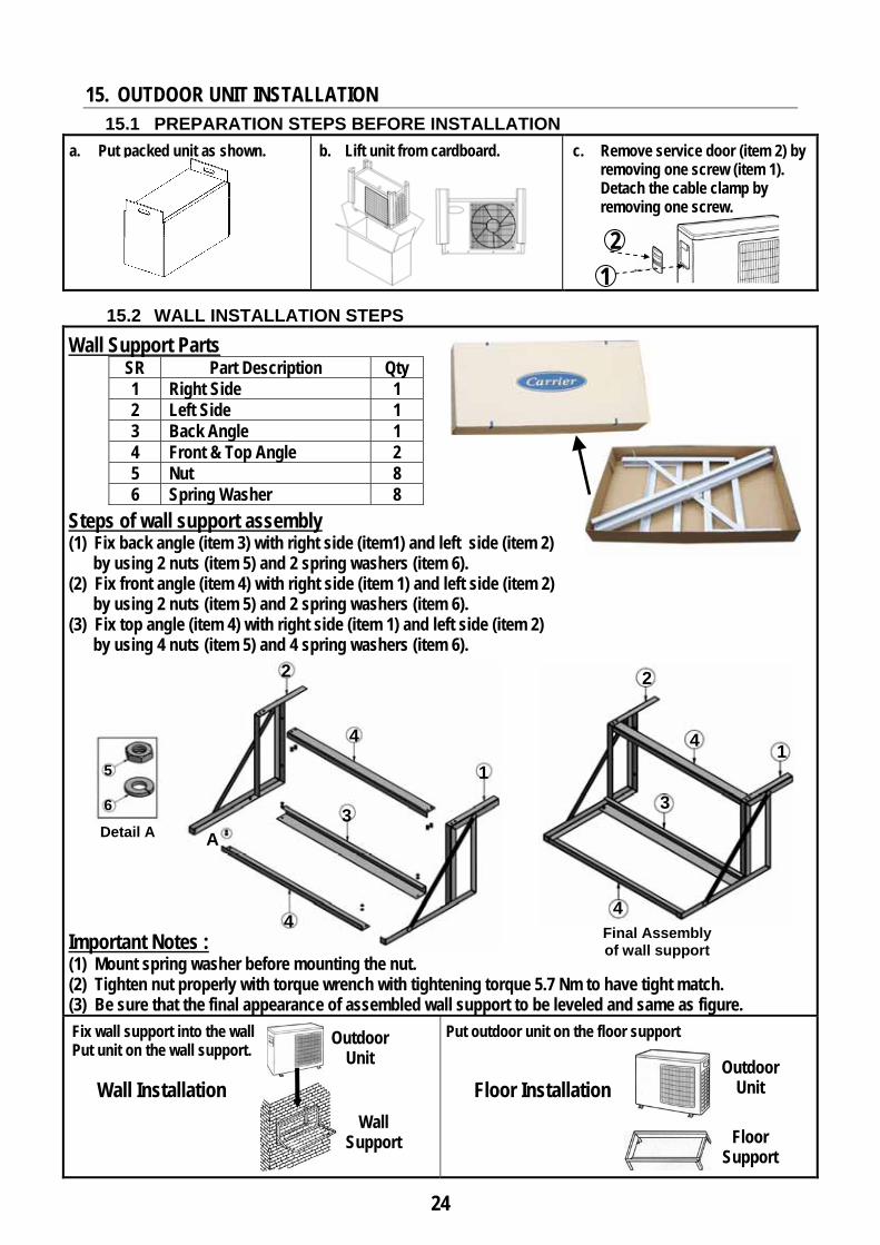
15. OUTDOOR UNIT INSTALLATION
15.1 PREPARATION STEPS BEFORE INSTALLATION
a. Put packed unit as shown.
b. Lift unit from cardboard.
c. Remove service door (item 2) by removing one screw (item 1).
Detach the cable clamp by removing one screw.
15.2 WALL INSTALLATION STEPS
Wall Support Parts SR Part Description Qty 1 Right Side 1 2 Left Side 1 3 Back Angle 1 4 Front & Top Angle 2 5 Nut 8 6 Spring Washer 8
Steps of wall support assembly (1) Fix back angle (item 3) with right side (item1) and left side (item 2) by using 2 nuts (item 5) and 2 spring washers (item 6). (2) Fix front angle (item 4) with right side (item 1) and left side (item 2) by using 2 nuts (item 5) and 2 spring washers (item 6). (3) Fix top angle (item 4) with right side (item 1) and left side (item 2) by using 4 nuts (item 5) and 4 spring washers (item 6).
Important Notes : (1) Mount spring washer before mounting the nut. (2) Tighten nut properly with torque wrench with tightening torque 5.7 Nm to have tight match. (3) Be sure that the final appearance of assembled wall support to be leveled and same as figure.
Fix wall support into the wall Put unit on the wall support. Wall Installation
Put outdoor unit on the floor support Floor Installation
1 2
Detail A
5
6
Floor Support
Outdoor Unit
Outdoor Unit
Wall Support
25
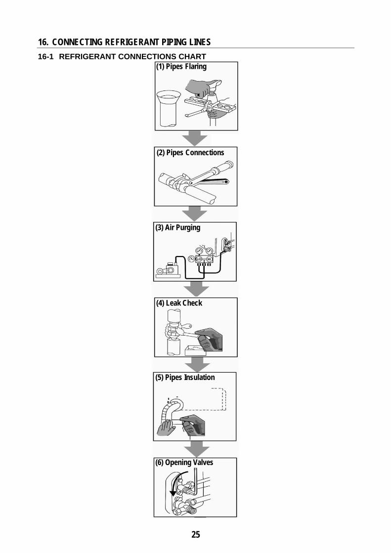
16. CONNECTING REFRIGERANT PIPING LINES
16-1 REFRIGERANT CONNECTIONS CHART
(1) Pipes Flaring
(2) Pipes Connections
(3) Air Purging
(4) Leak Check
(5) Pipes Insulation
(6) Opening Valves
26
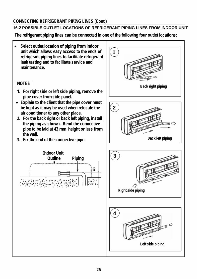
CONNECTING REFRIGERANT PIPING LINES (Cont.)
16-2 POSSIBLE OUTLET LOCATIONS OF REFRIGERANT PIPING LINES FROM INDOOR UNIT
The refrigerant piping lines can be connected in one of the following four outlet locations:
• Select outlet location of piping from indoor unit which allows easy access to the ends of refrigerant piping lines to facilitate refrigerant leak testing and to facilitate service and maintenance.
NOTES 1. For right side or left side piping, remove the
pipe cover from side panel. • Explain to the client that the pipe cover must
be kept as it may be used when relocate the air conditioner to any other place.
2. For the back right or back left piping, install the piping as shown. Bend the connective pipe to be laid at 43 mm height or less from the wall.
3. Fix the end of the connective pipe.
Indoor Unit Outline Piping
Back right piping
Back left piping
Right side piping
Left side piping
1
2
3
4
27
CONNECTING REFRIGERANT PIPING LINES (Cont.)
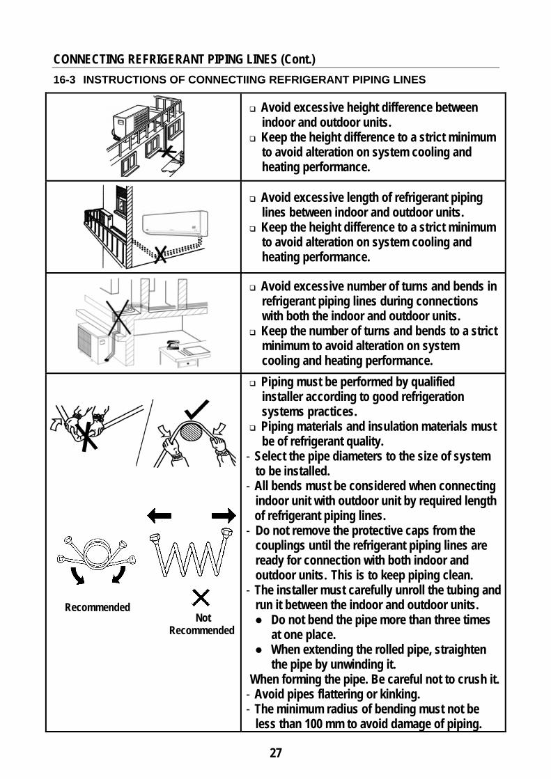
16-3 INSTRUCTIONS OF CONNECTIING REFRIGERANT PIPING LINES
Avoid excessive height difference between indoor and outdoor units.
Keep the height difference to a strict minimum to avoid alteration on system cooling and heating performance.
Avoid excessive length of refrigerant piping lines between indoor and outdoor units.
Keep the height difference to a strict minimum to avoid alteration on system cooling and heating performance.
Avoid excessive number of turns and bends in refrigerant piping lines during connections with both the indoor and outdoor units.
Keep the number of turns and bends to a strict minimum to avoid alteration on system cooling and heating performance.
Piping must be performed by qualified installer according to good refrigeration systems practices.
Piping materials and insulation materials must be of refrigerant quality.
- Select the pipe diameters to the size of system to be installed.
- All bends must be considered when connecting indoor unit with outdoor unit by required length
of refrigerant piping lines. - Do not remove the protective caps from the
couplings until the refrigerant piping lines are ready for connection with both indoor and outdoor units. This is to keep piping clean.
- The installer must carefully unroll the tubing and run it between the indoor and outdoor units. ● Do not bend the pipe more than three times
at one place. ● When extending the rolled pipe, straighten
the pipe by unwinding it. When forming the pipe. Be careful not to crush it.
- Avoid pipes flattering or kinking. - The minimum radius of bending must not be
less than 100 mm to avoid damage of piping.
Not Recommended
Recommended
28
CONNECTING REFRIGERANT PIPING LINES (Cont.)
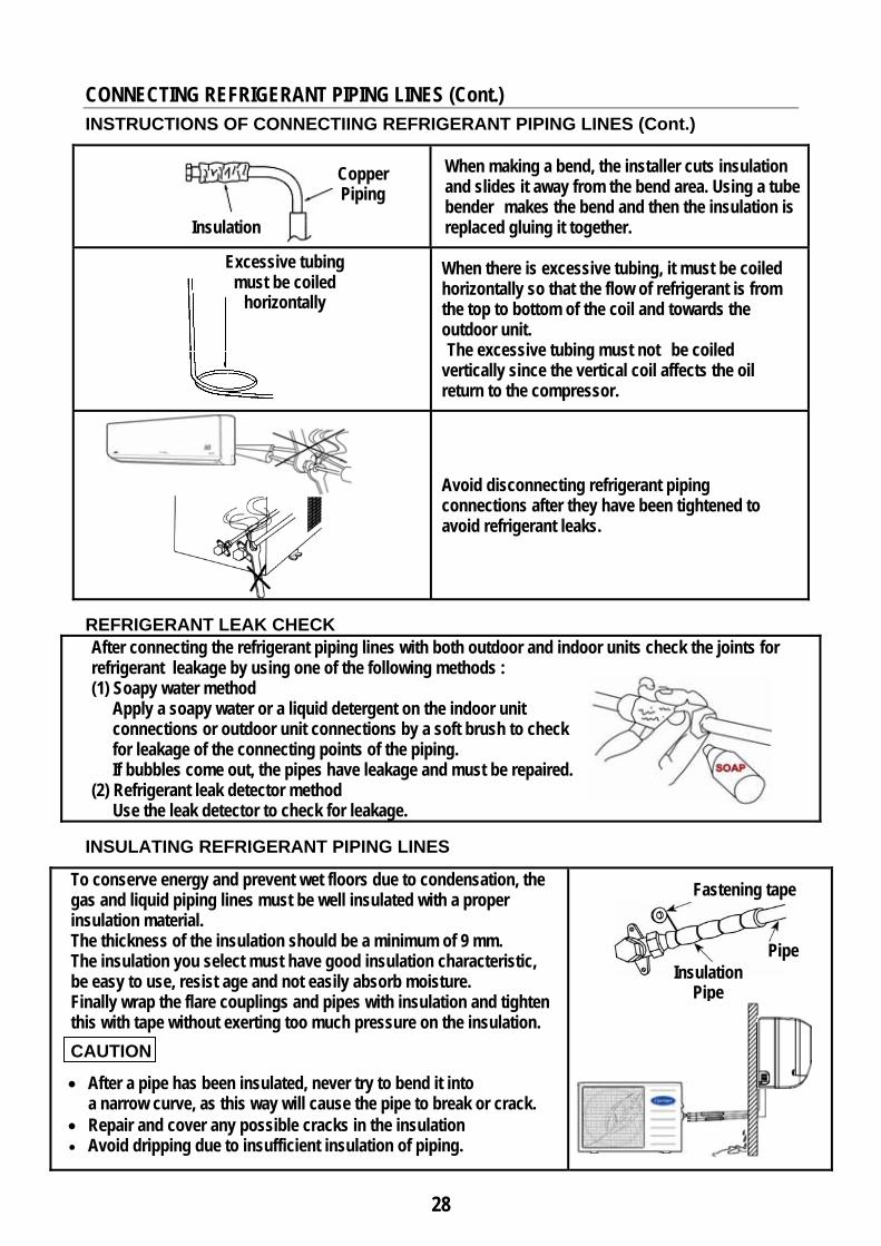
INSTRUCTIONS OF CONNECTIING REFRIGERANT PIPING LINES (Cont.) When making a bend, the installer cuts insulation
and slides it away from the bend area. Using a tube bender makes the bend and then the insulation is replaced gluing it together.
When there is excessive tubing, it must be coiled horizontally so that the flow of refrigerant is from the top to bottom of the coil and towards the outdoor unit. The excessive tubing must not be coiled vertically since the vertical coil affects the oil return to the compressor.
Avoid disconnecting refrigerant piping connections after they have been tightened to avoid refrigerant leaks.
REFRIGERANT LEAK CHECK After connecting the refrigerant piping lines with both outdoor and indoor units check the joints for refrigerant leakage by using one of the following methods : (1) Soapy water method
Apply a soapy water or a liquid detergent on the indoor unit connections or outdoor unit connections by a soft brush to check for leakage of the connecting points of the piping. If bubbles come out, the pipes have leakage and must be repaired.
(2) Refrigerant leak detector method Use the leak detector to check for leakage.
INSULATING REFRIGERANT PIPING LINES
To conserve energy and prevent wet floors due to condensation, the gas and liquid piping lines must be well insulated with a proper insulation material. The thickness of the insulation should be a minimum of 9 mm. The insulation you select must have good insulation characteristic, be easy to use, resist age and not easily absorb moisture. Finally wrap the flare couplings and pipes with insulation and tighten this with tape without exerting too much pressure on the insulation.
CAUTION
• After a pipe has been insulated, never try to bend it into a narrow curve, as this way will cause the pipe to break or crack.
• Repair and cover any possible cracks in the insulation • Avoid dripping due to insufficient insulation of piping.
Excessive tubing must be coiled
horizontally
Insulation
Copper Piping
Pipe Insulation
Pipe
Fastening tape
29
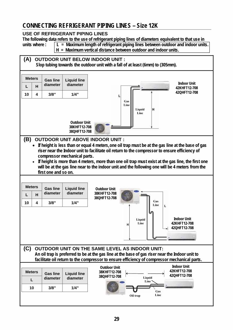
CONNECTING REFRIGERANT PIPING LINES – Size 12K
USE OF REFRIGERANT PIPING LINES The following data refers to the use of refrigerant piping lines of diameters equivalent to that use in units where : L = Maximum length of refrigerant piping lines between outdoor and indoor units.
H = Maximum vertical distance between outdoor and indoor units.
(A) OUTDOOR UNIT BELOW INDOOR UNIT : Slop tubing towards the outdoor unit with a fall of at least (6mm) to (305mm).
(B) OUTDOOR UNIT ABOVE INDOOR UNIT :
• If height is less than or equal 4 meters, one oil trap must be at the gas line at the base of gas riser near the Indoor unit to facilitate oil return to the compressor to ensure efficiency of compressor mechanical parts.
• If height is more than 4 meters, more than one oil trap must exist at the gas line, the first one will be at the gas line near to the indoor unit and the following one will be 4 meters from the first one and so on.
(C) OUTDOOR UNIT ON THE SAME LEVEL AS INDOOR UNIT: An oil trap is preferred to be at the gas line at the base of gas riser near the Indoor unit to
facilitate oil return to the compressor to ensure efficiency of compressor mechanical parts.
Meters Gas line diameter
Liquid line diameter L H
10 4 3/8” 1/4”
Outdoor Unit 38KHFT12-708 38QHFT12-708
Indoor Unit 42KHFT12-708 42QHFT12-708
Meters Gas line diameter
Liquid line diameter L H
10 4 3/8” 1/4”
Meters Gas line diameter
Liquid line diameter L
10 3/8” 1/4” Oil trap
Liquid Line
Gas Line
Liquid Line
Gas Line
Liquid Line
Gas Line
Outdoor Unit 38KHFT12-708 38QHFT12-708
Indoor Unit 42KHFT12-708 42QHFT12-708
Indoor Unit 42KHFT12-708 42QHFT12-708
Outdoor Unit 38KHFT12-708 38QHFT12-708

30
CONNECTING REFRIGERANT PIPING LINES – Size 18K
USE OF REFRIGERANT PIPING LINES The following data refers to the use of refrigerant piping lines of diameters equivalent to that use in units where : L = Maximum length of refrigerant piping lines between outdoor and indoor units.
H = Maximum vertical distance between outdoor and indoor units.
(A) OUTDOOR UNIT BELOW INDOOR UNIT : Slop tubing towards the outdoor unit with a fall of at least (6mm) to (305mm).
(B) OUTDOOR UNIT ABOVE INDOOR UNIT :
• If height is less than or equal 4 meters, one oil trap must be at the gas line at the base of gas riser near the Indoor unit to facilitate oil return to the compressor to ensure efficiency of compressor mechanical parts.
• If height is more than 4 meters, more than one oil trap must exist at the gas line, the first one will be at the gas line near to the indoor unit and the following one will be 4 meters from the first one and so on.
(C) OUTDOOR UNIT ON THE SAME LEVEL AS INDOOR UNIT: An oil trap is preferred to be at the gas line at the base of gas riser near the Indoor unit to
facilitate oil return to the compressor to ensure efficiency of compressor mechanical parts.
Meters Gas line diameter
Liquid line diameter L H
15 8 1/2” 1/4”
Meters Gas line diameter
Liquid line diameter L H
15 8 1/2” 1/4”
Meters Gas line diameter
Liquid line diameter L
15 1/2” 1/4” Oil trap
Liquid Line
Gas Line
Liquid Line
Gas Line
Outdoor Unit 38KHFT18-708 38QHFT18-708
Indoor Unit 42KHFT18-708 42QHFT18-708
Outdoor Unit 38KHFT18-708 38QHFT18-708
Liquid Line
Gas Line
Indoor Unit 42KHFT18-708 42QHFT18-708
Indoor Unit 42KHFT18-708 42QHFT18-708
Outdoor Unit 38KHFT18-708 38QHFT18-708
31
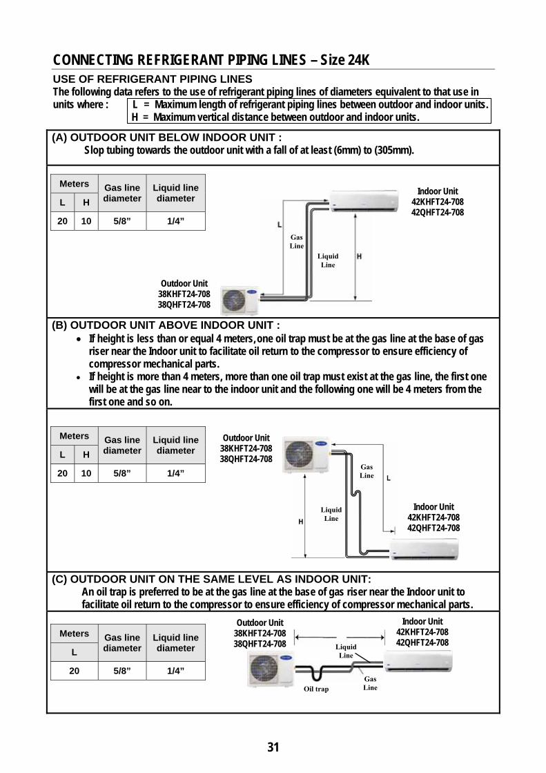
CONNECTING REFRIGERANT PIPING LINES – Size 24K
USE OF REFRIGERANT PIPING LINES The following data refers to the use of refrigerant piping lines of diameters equivalent to that use in units where : L = Maximum length of refrigerant piping lines between outdoor and indoor units.
H = Maximum vertical distance between outdoor and indoor units.
(A) OUTDOOR UNIT BELOW INDOOR UNIT : Slop tubing towards the outdoor unit with a fall of at least (6mm) to (305mm).
(B) OUTDOOR UNIT ABOVE INDOOR UNIT :
• If height is less than or equal 4 meters, one oil trap must be at the gas line at the base of gas riser near the Indoor unit to facilitate oil return to the compressor to ensure efficiency of compressor mechanical parts.
• If height is more than 4 meters, more than one oil trap must exist at the gas line, the first one will be at the gas line near to the indoor unit and the following one will be 4 meters from the first one and so on.
(C) OUTDOOR UNIT ON THE SAME LEVEL AS INDOOR UNIT: An oil trap is preferred to be at the gas line at the base of gas riser near the Indoor unit to
facilitate oil return to the compressor to ensure efficiency of compressor mechanical parts.
Meters Gas line diameter
Liquid line diameter L H
20 10 5/8” 1/4”
Meters Gas line diameter
Liquid line diameter L H
20 10 5/8” 1/4”
Meters Gas line diameter
Liquid line diameter L
20 5/8” 1/4” Oil trap
Liquid Line
Gas Line
Liquid Line
Gas Line
Outdoor Unit 38KHFT24-708 38QHFT24-708
Indoor Unit 42KHFT24-708 42QHFT24-708
Outdoor Unit 38KHFT24-708 38QHFT24-708
Liquid Line
Gas Line
Indoor Unit 42KHFT24-708 42QHFT24-708
Indoor Unit 42KHFT24-708 42QHFT24-708
Outdoor Unit 38KHFT24-708 38QHFT24-708
32
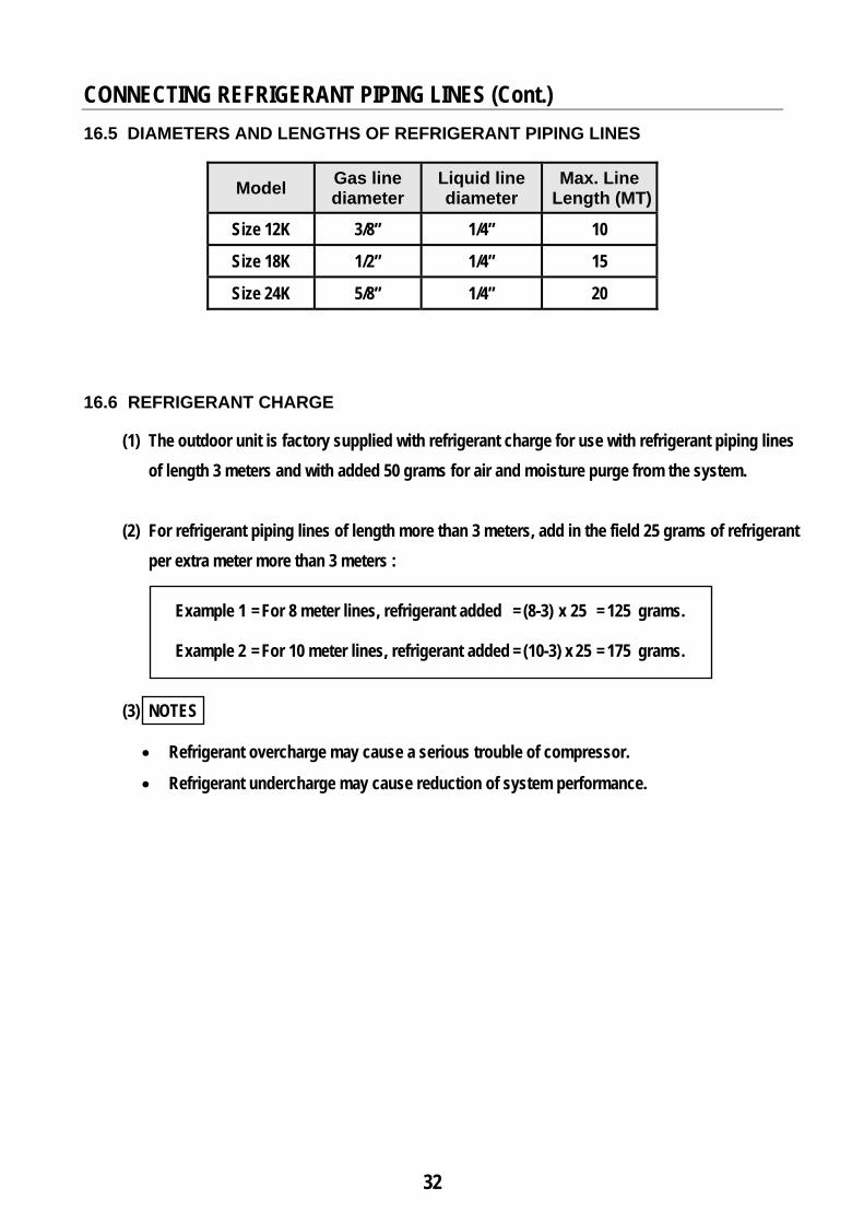
CONNECTING REFRIGERANT PIPING LINES (Cont.) 16.5 DIAMETERS AND LENGTHS OF REFRIGERANT PIPING LINES
Model Gas line diameter
Liquid line diameter
Max. Line Length (MT)
Size 12K 3/8” 1/4” 10
Size 18K 1/2” 1/4” 15
Size 24K 5/8” 1/4” 20 16.6 REFRIGERANT CHARGE
(1) The outdoor unit is factory supplied with refrigerant charge for use with refrigerant piping lines of length 3 meters and with added 50 grams for air and moisture purge from the system.
(2) For refrigerant piping lines of length more than 3 meters, add in the field 25 grams of refrigerant
per extra meter more than 3 meters :
Example 1 = For 8 meter lines, refrigerant added = (8-3) x 25 = 125 grams. Example 2 = For 10 meter lines, refrigerant added = (10-3) x 25 = 175 grams.
(3) NOTES
• Refrigerant overcharge may cause a serious trouble of compressor.
• Refrigerant undercharge may cause reduction of system performance.
33
CONNECTING REFRIGERANT PIPING (Cont.)
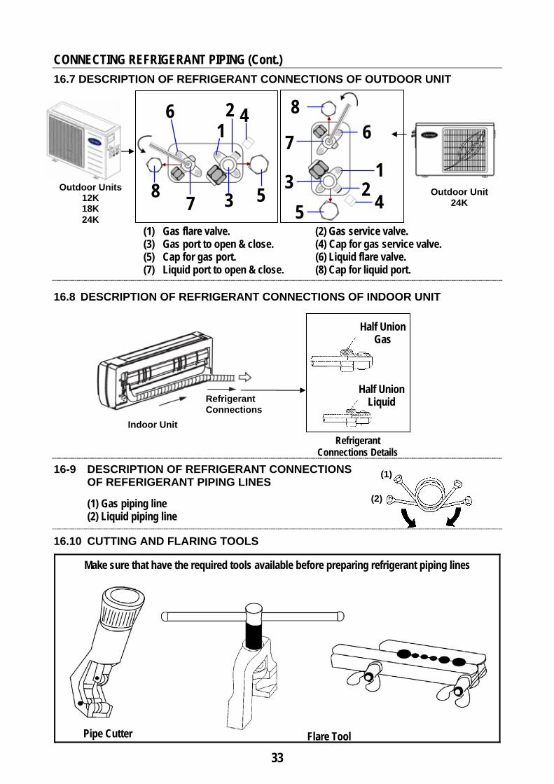
16.7 DESCRIPTION OF REFRIGERANT CONNECTIONS OF OUTDOOR UNIT
(1) Gas flare valve. (2) Gas service valve. (3) Gas port to open & close. (4) Cap for gas service valve. (5) Cap for gas port. (6) Liquid flare valve. (7) Liquid port to open & close. (8) Cap for liquid port.
16.8 DESCRIPTION OF REFRIGERANT CONNECTIONS OF INDOOR UNIT
Refrigerant Connections Details
16-9 DESCRIPTION OF REFRIGERANT CONNECTIONS OF REFERIGERANT PIPING LINES
(1) Gas piping line (2) Liquid piping line
16.10 CUTTING AND FLARING TOOLS
Make sure that have the required tools available before preparing refrigerant piping lines
Half Union Gas
Half Union Liquid
Pipe Cutter Flare Tool
Indoor Unit
Refrigerant Connections
(1)
(2)
4
5
2
3
1
7
6
8 Outdoor Units 12K 18K 24K
4 5 2 3 1
7 6 8
Outdoor Unit 24K
34
Corrugated Cutting
Wrap Cutting
CONNECTING REFRIGERANT PIPING LINES (Cont.)
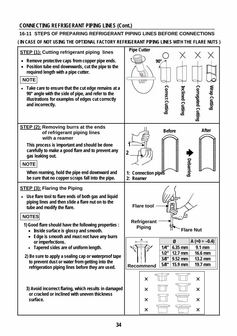
16-11 STEPS OF PREPARING REFRIGERANT PIPING LINES BEFORE CONNECTIONS ( IN CASE OF NOT USING THE OPTIONAL FACTORY REFRIGERANT PIPING LINES WITH THE FLARE NUTS )
STEP (1): Cutting refrigerant piping lines
• Remove protective caps from copper pipe ends. • Position tube end downwards, cut the pipe to the
required length with a pipe cutter.
NOTE • Take care to ensure that the cut edge remains at a
90° angle with the side of pipe, and refer to the illustrations for examples of edges cut correctly and incorrectly.
STEP (2): Removing burrs at the ends of refrigerant piping lines with a reamer
This process is important and should be done carefully to make a good flare and to prevent any gas leaking out.
NOTE When reaming, hold the pipe end downward and be sure that no copper scraps fall into the pipe.
STEP (3): Flaring the Piping • Use flare tool to flare ends of both gas and liquid
piping lines and then slide a flare nut on to the tube and modify the flare.
NOTES
1) Good flare should have the following properties : • Inside surface is glossy and smooth. • Edge is smooth and must not have any burrs
or imperfections. • Tapered sides are of uniform length.
2) Be sure to apply a sealing cap or waterproof tape to prevent dust or water from getting into the refrigeration piping lines before they are used.
3) Avoid incorrect flaring, which results in damaged or cracked or inclined with uneven thickness surface.
Debarring
After Before
Pipe Cutter
Correct Cutting
Inclined Cutting 90°
1
2
1: Connection pipes 2: Reamer
Recommend
Flare tool
Refrigerant Piping Flare Nut
Ø A (+0 ÷ –0.4) 1/4” 6.35 mm 9.1 mm 1/2” 12.7 mm 16.6 mm 3/8” 9.52 mm 13.2 mm 5/8” 15.9 mm 19.7 mm
35
CONNECTING REFRIGERANT PIPING LINES (Cont.)
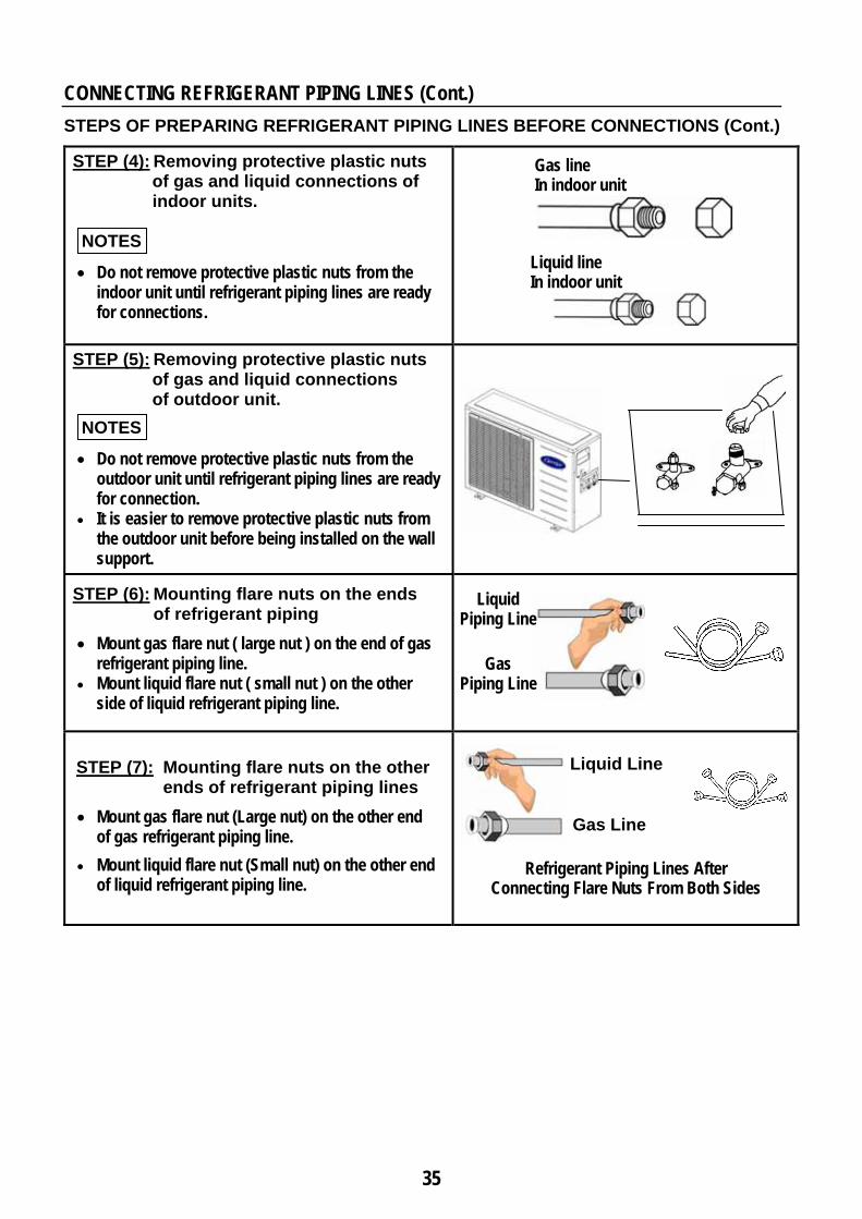
STEPS OF PREPARING REFRIGERANT PIPING LINES BEFORE CONNECTIONS (Cont.)
STEP (4): Removing protective plastic nuts of gas and liquid connections of indoor units.
NOTES
• Do not remove protective plastic nuts from the indoor unit until refrigerant piping lines are ready for connections.
STEP (5): Removing protective plastic nuts of gas and liquid connections of outdoor unit.
NOTES
• Do not remove protective plastic nuts from the outdoor unit until refrigerant piping lines are ready for connection.
• It is easier to remove protective plastic nuts from the outdoor unit before being installed on the wall support.
STEP (6): Mounting flare nuts on the ends of refrigerant piping
• Mount gas flare nut ( large nut ) on the end of gas refrigerant piping line.
• Mount liquid flare nut ( small nut ) on the other side of liquid refrigerant piping line.
STEP (7): Mounting flare nuts on the other ends of refrigerant piping lines
• Mount gas flare nut (Large nut) on the other end of gas refrigerant piping line.
• Mount liquid flare nut (Small nut) on the other end of liquid refrigerant piping line.
Gas line In indoor unit
Liquid line In indoor unit
Liquid Piping Line
Gas Piping Line
Liquid Line
Gas Line
Refrigerant Piping Lines After Connecting Flare Nuts From Both Sides
36
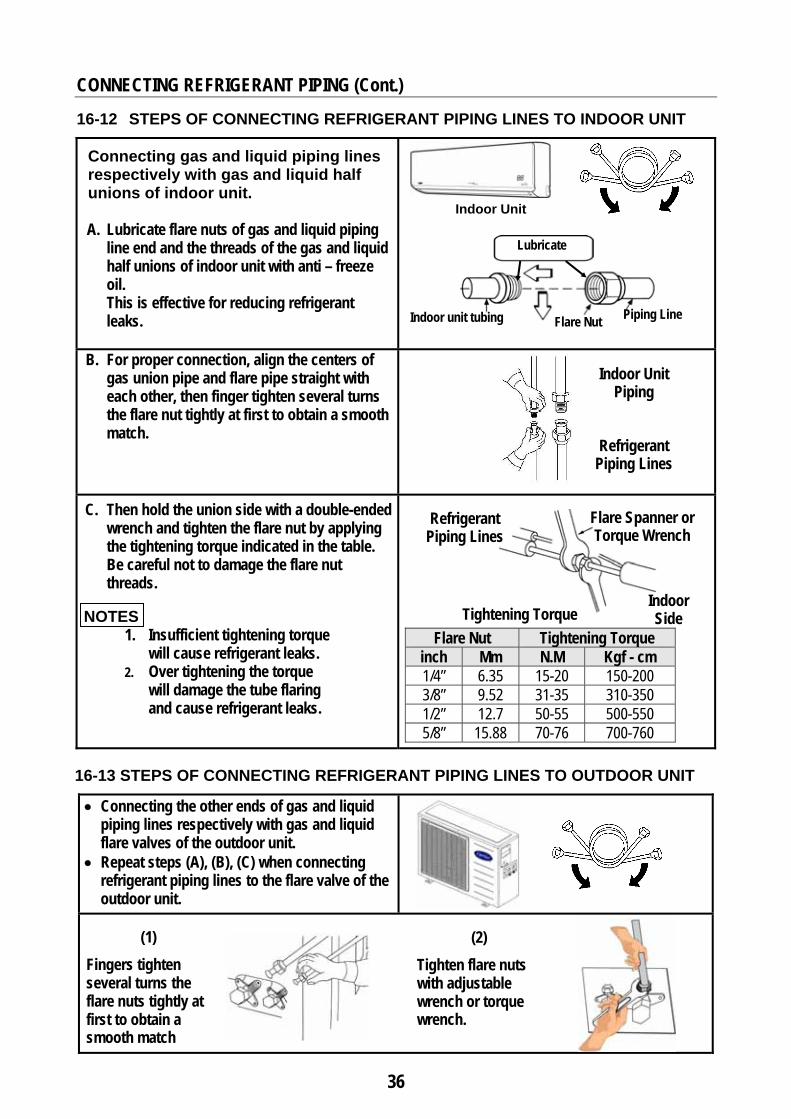
CONNECTING REFRIGERANT PIPING (Cont.) 16-12 STEPS OF CONNECTING REFRIGERANT PIPING LINES TO INDOOR UNIT
Connecting gas and liquid piping lines respectively with gas and liquid half unions of indoor unit.
A. Lubricate flare nuts of gas and liquid piping
line end and the threads of the gas and liquid half unions of indoor unit with anti – freeze oil. This is effective for reducing refrigerant leaks.
B. For proper connection, align the centers of gas union pipe and flare pipe straight with each other, then finger tighten several turns the flare nut tightly at first to obtain a smooth match.
C. Then hold the union side with a double-ended wrench and tighten the flare nut by applying the tightening torque indicated in the table. Be careful not to damage the flare nut threads.
NOTES
1. Insufficient tightening torque will cause refrigerant leaks.
2. Over tightening the torque will damage the tube flaring and cause refrigerant leaks.
16-13 STEPS OF CONNECTING REFRIGERANT PIPING LINES TO OUTDOOR UNIT
• Connecting the other ends of gas and liquid piping lines respectively with gas and liquid flare valves of the outdoor unit.
• Repeat steps (A), (B), (C) when connecting refrigerant piping lines to the flare valve of the outdoor unit.
Lubricate
(1) Fingers tighten several turns the flare nuts tightly at first to obtain a smooth match
Flare Spanner or Torque Wrench
Indoor Side
(2) Tighten flare nuts with adjustable wrench or torque wrench.
Indoor Unit Piping
Refrigerant Piping Lines
Indoor unit tubing Piping Line Flare Nut
Refrigerant Piping Lines
Indoor Unit
Tightening Torque Flare Nut Tightening Torque
inch Mm N.M Kgf - cm 1/4” 6.35 15-20 150-200 3/8” 9.52 31-35 310-350 1/2” 12.7 50-55 500-550 5/8” 15.88 70-76 700-760
37
CONNECTING REFRIGERANT PIPING LINES (Cont.)
16-14 AIR PURGING OF INDOOR UNIT AND REFRIGERANT PIPING LINES
16-14-1 INTRODUCTION
• In some countries the law does not permit purging by blowing refrigerant through the lines. If this is the case, please refer to page using the vacuum pump.
• The air in the indoor unit and in the refrigerant piping must be purged. If air remains in the refrigeration piping, it will have undesirable effects as indicated below :
Pressure in the system rises. Operating current rises. Cooling and heating efficiency drops. Moisture in the refrigerant circuit may freeze and block capillary tubing. Water may lead to corrosion of parts in the refrigeration system.
• Be sure, using a torque wrench to tighten the service port cap ( after using the service port ), so that it prevents the gas leakage from the refrigeration cycle.
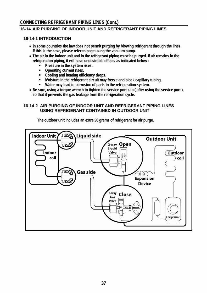
16-14-2 AIR PURGING OF INDOOR UNIT AND REFRIGERANT PIPING LINES USING REFRIGERANT CONTAINED IN OUTDOOR UNIT The outdoor unit includes an extra 50 grams of refrigerant for air purge.
38
CONNECTING REFRIGERANT PIPING LINES (Cont.)
AIR PURGING OF INDOOR UNIT AND REFRIGERANT PIPING LINES USING REFRIGERANT CONTAINED IN OUTDOOR UNIT (Cont.)
Air purging procedure (1) Recheck the refrigerant piping connections. (2) Open the valve stem of the 2-way liquid valve counterclockwise approximately 90°,
wait 10 seconds, and then set it to closed position.
• Be sure to use a hexagonal wrench to operate the valve stem. (3) Check for gas leakage from flare connections. (4) Purge the air from the system
• Set the 2-way liquid valve to the open position and remove the cap from the 3-way gas valve’s service port.
• Using the hexagonal wrench to press the valve core pin, discharge for three seconds and then wait for one minute.
(5) Use torque wrench to tighten the service port cap to a torque of 1.8 kg.m. (18 Nm) (6) Set the 3-way gas valve to the open position. (7) Mount the valve stem nuts to the 2-way liquid and 3-way gas valves. (8) Check for gas leakage.
• At this time, especially check for gas leakage from the 2-way and 3-way stem nuts, and from the service port.
CAUTION
If gas leakage is discovered in step (3) above, take the following measures.
• If the leaks stop when the piping connections are tightened further, continue working from step (4).
• If the gas leaks do not stop when the connections are retightened, repair the location of the leak, discharge all of the gas through the service port, and then recharge with the specified amount of gas from a gas cylinder.
39
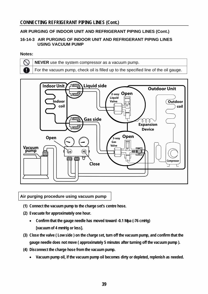
CONNECTING REFRIGERANT PIPING LINES (Cont.) AIR PURGING OF INDOOR UNIT AND REFRIGERANT PIPING LINES (Cont.) 16-14-3 AIR PURGING OF INDOOR UNIT AND REFRIGERANT PIPING LINES
USING VACUUM PUMP Notes:
NEVER use the system compressor as a vacuum pump.
For the vacuum pump, check oil is filled up to the specified line of the oil gauge.
Air purging procedure using vacuum pump
(1) Connect the vacuum pump to the charge set’s centre hose. (2) Evacuate for approximately one hour.
• Confirm that the gauge needle has moved toward -0.1 Mpa (-76 cmHg) [vacuum of 4 mmHg or less].
(3) Close the valve ( Low side ) on the charge set, turn off the vacuum pump, and confirm that the gauge needle does not move ( approximately 5 minutes after turning off the vacuum pump ).
(4) Disconnect the charge hose from the vacuum pump.
• Vacuum pump oil, if the vacuum pump oil becomes dirty or depleted, replenish as needed.
40
CONNECTING REFRIGERANT PIPING LINES (Cont.)
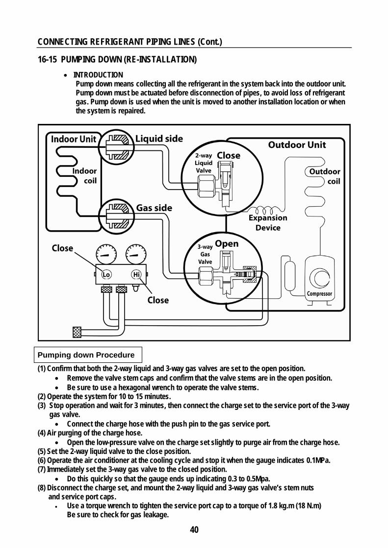
16-15 PUMPING DOWN (RE-INSTALLATION) • INTRODUCTION
Pump down means collecting all the refrigerant in the system back into the outdoor unit. Pump down must be actuated before disconnection of pipes, to avoid loss of refrigerant gas. Pump down is used when the unit is moved to another installation location or when the system is repaired.
Pumping down Procedure (1) Confirm that both the 2-way liquid and 3-way gas valves are set to the open position.
• Remove the valve stem caps and confirm that the valve stems are in the open position. • Be sure to use a hexagonal wrench to operate the valve stems.
(2) Operate the system for 10 to 15 minutes. (3) Stop operation and wait for 3 minutes, then connect the charge set to the service port of the 3-way
gas valve. • Connect the charge hose with the push pin to the gas service port.
(4) Air purging of the charge hose. • Open the low-pressure valve on the charge set slightly to purge air from the charge hose.
(5) Set the 2-way liquid valve to the close position. (6) Operate the air conditioner at the cooling cycle and stop it when the gauge indicates 0.1MPa. (7) Immediately set the 3-way gas valve to the closed position.
• Do this quickly so that the gauge ends up indicating 0.3 to 0.5Mpa. (8) Disconnect the charge set, and mount the 2-way liquid and 3-way gas valve’s stem nuts and service port caps.
• Use a torque wrench to tighten the service port cap to a torque of 1.8 kg.m (18 N.m) Be sure to check for gas leakage.
41
Move and tape the drain hose with piping in a position as mentioned in figures Cover for the
left pipingCover for the right piping
Rubber Plug Cover for piping
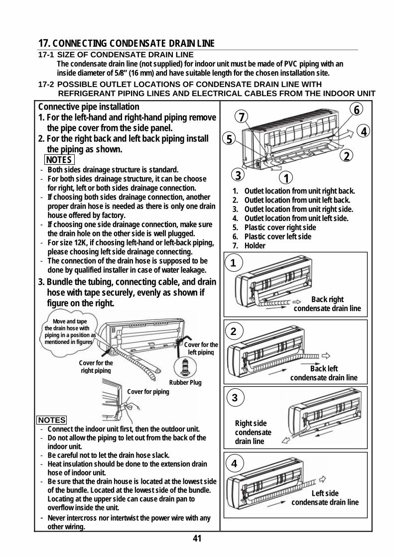
17. CONNECTING CONDENSATE DRAIN LINE 17-1 SIZE OF CONDENSATE DRAIN LINE
The condensate drain line (not supplied) for indoor unit must be made of PVC piping with an inside diameter of 5/8” (16 mm) and have suitable length for the chosen installation site.
17-2 POSSIBLE OUTLET LOCATIONS OF CONDENSATE DRAIN LINE WITH REFRIGERANT PIPING LINES AND ELECTRICAL CABLES FROM THE INDOOR UNIT
Connective pipe installation 1. For the left-hand and right-hand piping remove
the pipe cover from the side panel. 2. For the right back and left back piping install
the piping as shown. NOTES
- Both sides drainage structure is standard. - For both sides drainage structure, it can be choose
for right, left or both sides drainage connection. - If choosing both sides drainage connection, another
proper drain hose is needed as there is only one drain house offered by factory.
- If choosing one side drainage connection, make sure the drain hole on the other side is well plugged.
- For size 12K, if choosing left-hand or left-back piping, please choosing left side drainage connecting.
- The connection of the drain hose is supposed to be done by qualified installer in case of water leakage.
3. Bundle the tubing, connecting cable, and drain hose with tape securely, evenly as shown if figure on the right.
NOTES - Connect the indoor unit first, then the outdoor unit. - Do not allow the piping to let out from the back of the
indoor unit. - Be careful not to let the drain hose slack. - Heat insulation should be done to the extension drain
hose of indoor unit. - Be sure that the drain house is located at the lowest side
of the bundle. Located at the lowest side of the bundle. Locating at the upper side can cause drain pan to overflow inside the unit.
- Never intercross nor intertwist the power wire with any other wiring.
1. Outlet location from unit right back. 2. Outlet location from unit left back. 3. Outlet location from unit right side. 4. Outlet location from unit left side. 5. Plastic cover right side 6. Plastic cover left side 7. Holder
3 1
2
4 5
6 7
Back right condensate drain line
Back left condensate drain line
Right side condensate drain line
Left side condensate drain line
1
2
3
4
42
CONNECTING CONDENSATE DRAIN LINE (Cont.)
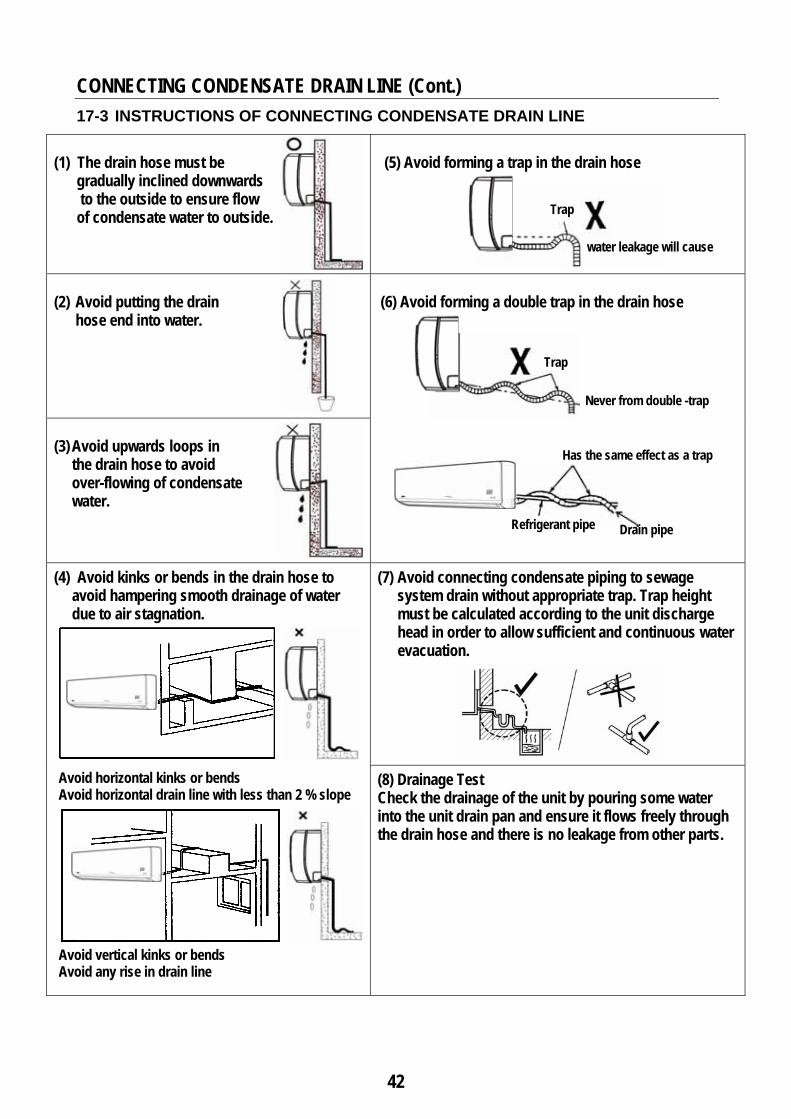
17-3 INSTRUCTIONS OF CONNECTING CONDENSATE DRAIN LINE
(1) The drain hose must be
gradually inclined downwards to the outside to ensure flow of condensate water to outside.
(5) Avoid forming a trap in the drain hose
(2) Avoid putting the drain
hose end into water.
(6) Avoid forming a double trap in the drain hose
(3) Avoid upwards loops in
the drain hose to avoid over-flowing of condensate water.
(4) Avoid kinks or bends in the drain hose to avoid hampering smooth drainage of water due to air stagnation.
Avoid horizontal kinks or bends Avoid horizontal drain line with less than 2 % slope
Avoid vertical kinks or bends Avoid any rise in drain line
(7) Avoid connecting condensate piping to sewage system drain without appropriate trap. Trap height must be calculated according to the unit discharge head in order to allow sufficient and continuous water evacuation.
(8) Drainage Test Check the drainage of the unit by pouring some water into the unit drain pan and ensure it flows freely through the drain hose and there is no leakage from other parts.
Trap
water leakage will cause
Trap
Never from double -trap
Has the same effect as a trap
Refrigerant pipe Drain pipe
43
18. CONNECTING ELECTRICAL WIRING 18-1 ELECTRICAL WIRING BETWEEN ELECTRICAL POWER SUPPLY
AND CIRCUIT BREAKER OF AIR CONDITIONER All electrical connections between electrical power supply and circuit breaker of air conditioner are the responsibility of the customer and must be done by a qualified electrical technician according to national electrical wiring regulations to avoid fire due to short-circuiting.
(A) Operating Voltage The operating voltage of electrical power supply should be within the limits of voltage mentioned
on unit nameplate data. (B) Electrical kWh Counter KWH The capacity of electrical kWh counter should be lager than the operating currents required for air
conditioner(s) and any other electrical domestic appliances in use simultaneously from the same supply.
(C) Electrical Distribution Box The installation of electrical distribution box after the electrical KWH counter is necessary
to properly distribute the electrical loads. The electrical distribution box should be equipped with circuit breakers according to the electrical
loads. For each installed air conditioner, a separate circuit breaker with its own overload should be
installed on the electrical distribution box. (D) Operation On / Off Circuit Breaker The installation of two pole automatic circuit breaker is necessary to operate the air conditioner.
The circuit breaker must be installed to be far away from any flammable materials (curtains…etc.). The circuit breaker must be suitable for air conditioner as the table “ ELECTRICAL DATA “ Page (45) Do not use operation ON / OFF circuit breakers except the approved models for use with air
conditioners. (E) Electrical Cable Do not use electrical connection cables except the approved for use with air conditioners. The power cable should be a complete unit, without extensions. The power cable size must be suitable for the air conditioner with length up to 10 meter.
See table “ ELECTRICAL DATA “ page (45).
(F) Electrical Wiring a. Make ground connection prior to any other electrical connections in accordance with the
electrical codes.
b. Ensure that mains supply connection is made through a switch that disconnects all poles, with contact gap of at least 3 mm.
c. Avoid slack connections of the electrical cords when connected to the terminal blocks of indoor
and outdoor units. These slack connections lead to voltage drop and unit malfunctions.
WARNING
!
44
CONNECTING ELECTRICAL WIRING (Cont.)
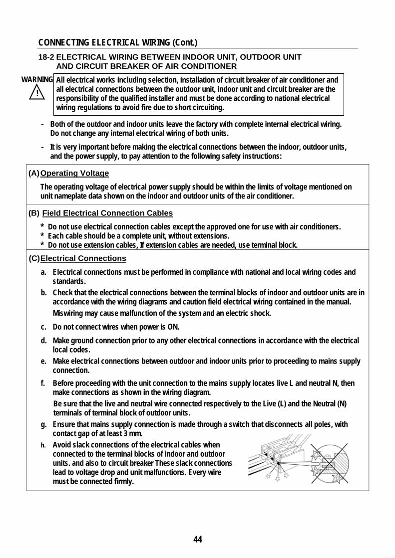
18-2 ELECTRICAL WIRING BETWEEN INDOOR UNIT, OUTDOOR UNIT AND CIRCUIT BREAKER OF AIR CONDITIONER
All electrical works including selection, installation of circuit breaker of air conditioner and all electrical connections between the outdoor unit, indoor unit and circuit breaker are the responsibility of the qualified installer and must be done according to national electrical wiring regulations to avoid fire due to short circuiting.
- Both of the outdoor and indoor units leave the factory with complete internal electrical wiring. Do not change any internal electrical wiring of both units. - It is very important before making the electrical connections between the indoor, outdoor units,
and the power supply, to pay attention to the following safety instructions:
(A) Operating Voltage The operating voltage of electrical power supply should be within the limits of voltage mentioned on
unit nameplate data shown on the indoor and outdoor units of the air conditioner.
(B) Field Electrical Connection Cables * Do not use electrical connection cables except the approved one for use with air conditioners. * Each cable should be a complete unit, without extensions. * Do not use extension cables, If extension cables are needed, use terminal block.
(C) Electrical Connections a. Electrical connections must be performed in compliance with national and local wiring codes and
standards.
b. Check that the electrical connections between the terminal blocks of indoor and outdoor units are in accordance with the wiring diagrams and caution field electrical wiring contained in the manual.
Miswiring may cause malfunction of the system and an electric shock. c. Do not connect wires when power is ON. d. Make ground connection prior to any other electrical connections in accordance with the electrical
local codes.
e. Make electrical connections between outdoor and indoor units prior to proceeding to mains supply connection.
f. Before proceeding with the unit connection to the mains supply locates live L and neutral N, then make connections as shown in the wiring diagram.
Be sure that the live and neutral wire connected respectively to the Live (L) and the Neutral (N) terminals of terminal block of outdoor units.
g. Ensure that mains supply connection is made through a switch that disconnects all poles, with contact gap of at least 3 mm.
h. Avoid slack connections of the electrical cables when connected to the terminal blocks of indoor and outdoor units. and also to circuit breaker These slack connections lead to voltage drop and unit malfunctions. Every wire must be connected firmly.
WARNING
!
45
CONNECTING ELECTRICAL WIRING (Cont.)
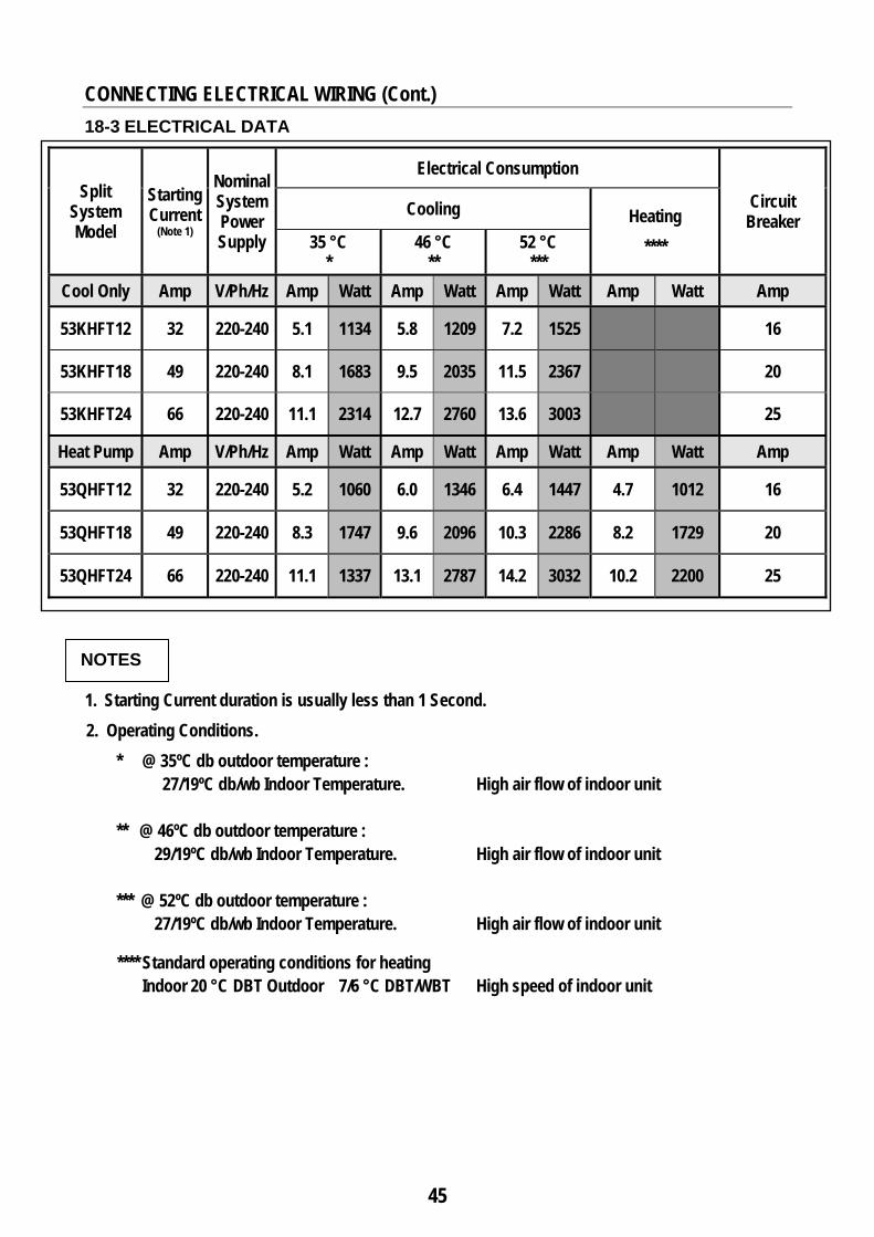
18-3 ELECTRICAL DATA
Split System Model
Starting Current
(Note 1)
Nominal System Power Supply
Electrical Consumption
Circuit Breaker
Cooling Heating **** 35 °C
* 46 °C
** 52 °C
*** Cool Only Amp V/Ph/Hz Amp Watt Amp Watt Amp Watt Amp Watt Amp
53KHFT12 32 220-240 5.1 1134 5.8 1209 7.2 1525 16
53KHFT18 49 220-240 8.1 1683 9.5 2035 11.5 2367 20
53KHFT24 66 220-240 11.1 2314 12.7 2760 13.6 3003 25
Heat Pump Amp V/Ph/Hz Amp Watt Amp Watt Amp Watt Amp Watt Amp
53QHFT12 32 220-240 5.2 1060 6.0 1346 6.4 1447 4.7 1012 16
53QHFT18 49 220-240 8.3 1747 9.6 2096 10.3 2286 8.2 1729 20
53QHFT24 66 220-240 11.1 1337 13.1 2787 14.2 3032 10.2 2200 25
NOTES
1. Starting Current duration is usually less than 1 Second. 2. Operating Conditions.
* @ 35ºC db outdoor temperature : 27/19ºC db/wb Indoor Temperature. High air flow of indoor unit
** @ 46ºC db outdoor temperature :
29/19ºC db/wb Indoor Temperature. High air flow of indoor unit *** @ 52ºC db outdoor temperature :
27/19ºC db/wb Indoor Temperature. High air flow of indoor unit
**** Standard operating conditions for heating Indoor 20 °C DBT Outdoor 7/6 °C DBT/WBT High speed of indoor unit
46
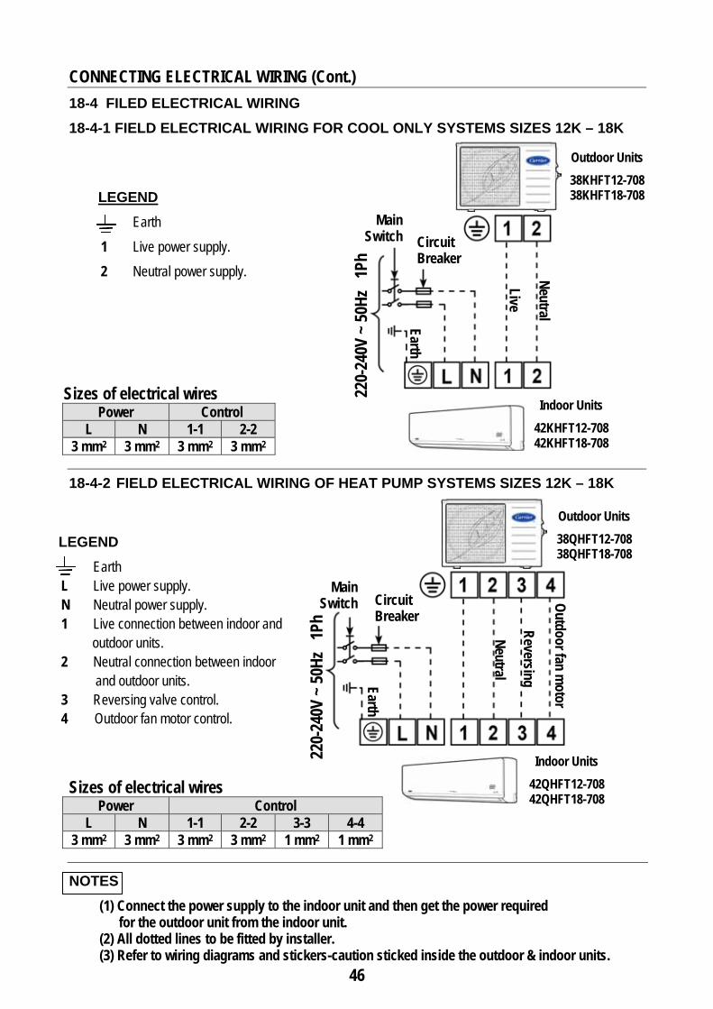
LEGEND Earth 1 Live power supply. 2 Neutral power supply.
LEGEND Earth L Live power supply. N Neutral power supply. 1 Live connection between indoor and
outdoor units. 2 Neutral connection between indoor
and outdoor units. 3 Reversing valve control. 4 Outdoor fan motor control.
CONNECTING ELECTRICAL WIRING (Cont.)
18-4 FILED ELECTRICAL WIRING 18-4-1 FIELD ELECTRICAL WIRING FOR COOL ONLY SYSTEMS SIZES 12K – 18K
Sizes of electrical wires Power Control
L N 1-1 2-2 3 mm2 3 mm2 3 mm2 3 mm2
18-4-2 FIELD ELECTRICAL WIRING OF HEAT PUMP SYSTEMS SIZES 12K – 18K Sizes of electrical wires
Power Control L N 1-1 2-2 3-3 4-4
3 mm2 3 mm2 3 mm2 3 mm2 1 mm2 1 mm2
NOTES (1) Connect the power supply to the indoor unit and then get the power required
for the outdoor unit from the indoor unit. (2) All dotted lines to be fitted by installer. (3) Refer to wiring diagrams and stickers-caution sticked inside the outdoor & indoor units.
Live Neutral
Circuit Breaker
Main Switch
Earth
Indoor Units 42KHFT12-708 42KHFT18-708
Outdoor Units 38KHFT12-708 38KHFT18-708
Circuit Breaker
Main Switch
Indoor Units 42QHFT12-708 42QHFT18-708
Outdoor Units 38QHFT12-708 38QHFT18-708
Neutral Reversing
Outdoor fan motor
Earth
220-
240V
~ 50
Hz 1
Ph
220-
240V
~ 50
Hz 1
Ph
47
CONNECTING ELECTRICAL WIRING (Cont.)
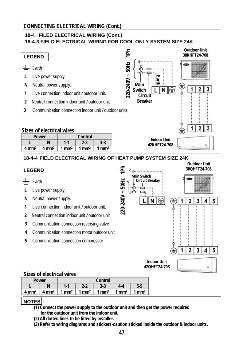
18-4 FILED ELECTRICAL WIRING (Cont.) 18-4-3 FIELD ELECTRICAL WIRING FOR COOL ONLY SYSTEM SIZE 24K LEGEND
Earth L Live power supply. N Neutral power supply. 1 Live connection indoor unit / outdoor unit. 2 Neutral connection indoor unit / outdoor unit 3 Communication connection indoor unit / outdoor units
Sizes of electrical wires Power Control
L N 1-1 2-2 3-3 4 mm2 4 mm2 1 mm2 1 mm2 1 mm2
18-4-4 FIELD ELECTRICAL WIRING OF HEAT PUMP SYSTEM SIZE 24K LEGEND
Earth L Live power supply. N Neutral power supply. 1 Live connection indoor unit / outdoor unit. 2 Neutral connection indoor unit / outdoor unit 3 Communication connection reversing valve
4 Communication connection motor outdoor unit 5 Communication connection compressor Sizes of electrical wires
Power Control L N 1-1 2-2 3-3 4-4 5-5
4 mm2 4 mm2 1 mm2 1 mm2 1 mm2 1 mm2 1 mm2
NOTES (1) Connect the power supply to the outdoor unit and then get the power required
for the outdoor unit from the indoor unit. (2) All dotted lines to be fitted by installer. (3) Refer to wiring diagrams and stickers-caution sticked inside the outdoor & indoor units.
Circuit Breaker
Main Switch
Earth
Indoor Unit 42KHFT24-708
Outdoor Unit 38KHFT24-708
220-
240V
~ 50
Hz 1
Ph
Outdoor Unit 38QHFT24-708
Indoor Unit 42QHFT24-708
220-
240V
~ 50
Hz 1
Ph
Circuit Breaker Main Switch
48
Piping
Decorative TapeSaddles
19. FINISHING INSTALLATION
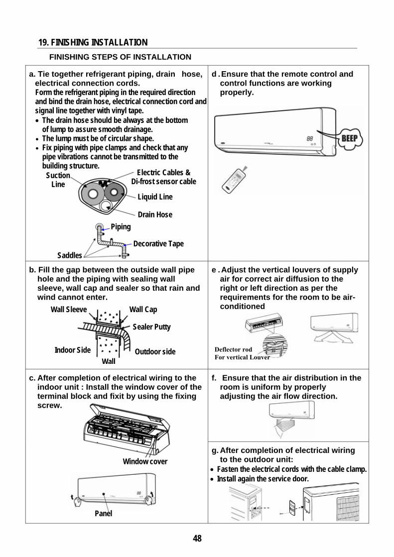
FINISHING STEPS OF INSTALLATION
a. Tie together refrigerant piping, drain hose, electrical connection cords. Form the refrigerant piping in the required direction and bind the drain hose, electrical connection cord and signal line together with vinyl tape. • The drain hose should be always at the bottom
of lump to assure smooth drainage. • The lump must be of circular shape. • Fix piping with pipe clamps and check that any
pipe vibrations cannot be transmitted to the building structure.
d . Ensure that the remote control and control functions are working properly.
b. Fill the gap between the outside wall pipe hole and the piping with sealing wall sleeve, wall cap and sealer so that rain and wind cannot enter.
e . Adjust the vertical louvers of supply air for correct air diffusion to the right or left direction as per the requirements for the room to be air-conditioned
c. After completion of electrical wiring to the indoor unit : Install the window cover of the terminal block and fixit by using the fixing screw.
f. Ensure that the air distribution in the room is uniform by properly adjusting the air flow direction.
g. After completion of electrical wiring to the outdoor unit:
• Fasten the electrical cords with the cable clamp. • Install again the service door.
Panel
Window cover
Wall Sleeve Wall Cap
Sealer Putty
Outdoor side Wall
Indoor Side
Electric Cables & Di-frost sensor cable
Liquid Line
Drain Hose
Suction Line
Deflector rod For vertical Louver
49
20. TEST RUNNING
20.1 PRECAUTIONS BEFORE TEST RUNNING
- Operate test running after checking that the air filters and front panel are properly mounted. - Operate testing running after completion of connecting refrigerant piping lines,
drain line and electrical wiring
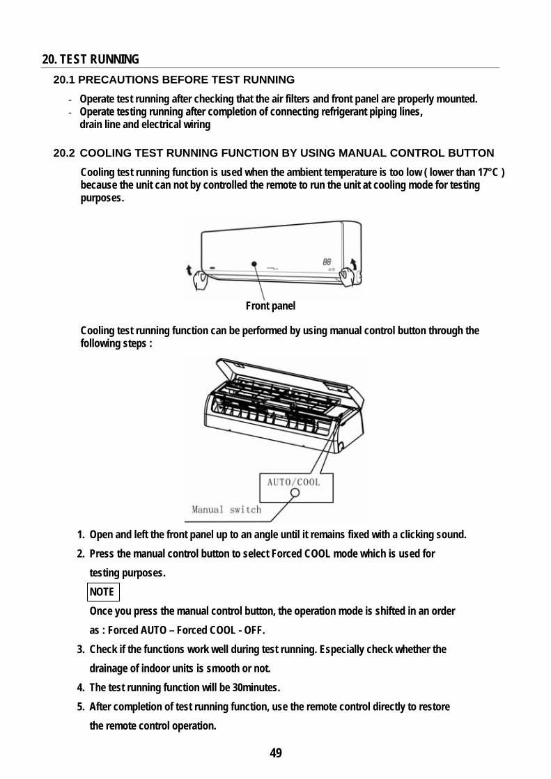
20.2 COOLING TEST RUNNING FUNCTION BY USING MANUAL CONTROL BUTTON Cooling test running function is used when the ambient temperature is too low ( lower than 17°C ) because the unit can not by controlled the remote to run the unit at cooling mode for testing purposes.
Cooling test running function can be performed by using manual control button through the following steps :
1. Open and left the front panel up to an angle until it remains fixed with a clicking sound. 2. Press the manual control button to select Forced COOL mode which is used for
testing purposes. NOTE Once you press the manual control button, the operation mode is shifted in an order as : Forced AUTO – Forced COOL - OFF.
3. Check if the functions work well during test running. Especially check whether the drainage of indoor units is smooth or not.
4. The test running function will be 30minutes. 5. After completion of test running function, use the remote control directly to restore
the remote control operation.
Front panel
50
TEST RUNNING (Cont.)
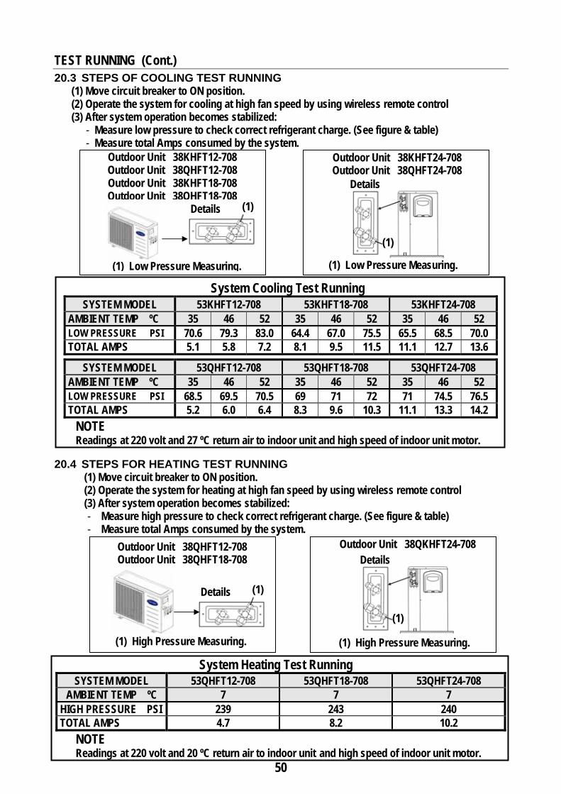
20.3 STEPS OF COOLING TEST RUNNING (1) Move circuit breaker to ON position. (2) Operate the system for cooling at high fan speed by using wireless remote control (3) After system operation becomes stabilized:
- Measure low pressure to check correct refrigerant charge. (See figure & table) - Measure total Amps consumed by the system.
System Cooling Test Running SYSTEM MODEL 53KHFT12-708 53KHFT18-708 53KHFT24-708
AMBIENT TEMP ºC 35 46 52 35 46 52 35 46 52 LOW PRESSURE PSI 70.6 79.3 83.0 64.4 67.0 75.5 65.5 68.5 70.0 TOTAL AMPS 5.1 5.8 7.2 8.1 9.5 11.5 11.1 12.7 13.6
SYSTEM MODEL 53QHFT12-708 53QHFT18-708 53QHFT24-708 AMBIENT TEMP ºC 35 46 52 35 46 52 35 46 52 LOW PRESSURE PSI 68.5 69.5 70.5 69 71 72 71 74.5 76.5 TOTAL AMPS 5.2 6.0 6.4 8.3 9.6 10.3 11.1 13.3 14.2
NOTE Readings at 220 volt and 27 ºC return air to indoor unit and high speed of indoor unit motor.
20.4 STEPS FOR HEATING TEST RUNNING
(1) Move circuit breaker to ON position. (2) Operate the system for heating at high fan speed by using wireless remote control (3) After system operation becomes stabilized: - Measure high pressure to check correct refrigerant charge. (See figure & table) - Measure total Amps consumed by the system.
System Heating Test Running SYSTEM MODEL 53QHFT12-708 53QHFT18-708 53QHFT24-708
AMBIENT TEMP ºC 7 7 7 HIGH PRESSURE PSI 239 243 240 TOTAL AMPS 4.7 8.2 10.2
NOTE Readings at 220 volt and 20 ºC return air to indoor unit and high speed of indoor unit motor.
(1)
Outdoor Unit 38KHFT12-708 Outdoor Unit 38QHFT12-708 Outdoor Unit 38KHFT18-708 Outdoor Unit 38QHFT18-708
Outdoor Unit 38KHFT24-708 Outdoor Unit 38QHFT24-708
Details
(1) Low Pressure Measuring. (1) Low Pressure Measuring.
(1)
Details
Outdoor Unit 38QHFT12-708 Outdoor Unit 38QHFT18-708
Outdoor Unit 38QKHFT24-708
(1)
(1) High Pressure Measuring.
Details
Details
(1) High Pressure Measuring.
(1)
51
21. AIR CIRCULATION FOR INDOOR UNIT AIR FLOW DIRECTION CONTROL
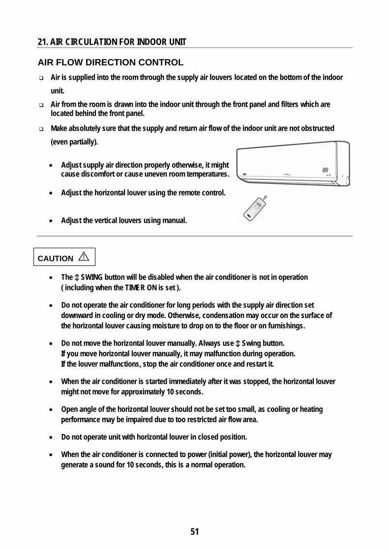
Air is supplied into the room through the supply air louvers located on the bottom of the indoor unit.
Air from the room is drawn into the indoor unit through the front panel and filters which are located behind the front panel.
Make absolutely sure that the supply and return air flow of the indoor unit are not obstructed
(even partially).
• Adjust supply air direction properly otherwise, it might cause discomfort or cause uneven room temperatures.
• Adjust the horizontal louver using the remote control.
• Adjust the vertical louvers using manual. CAUTION
• The ↕ SWING button will be disabled when the air conditioner is not in operation ( including when the TIMER ON is set ).
• Do not operate the air conditioner for long periods with the supply air direction set downward in cooling or dry mode. Otherwise, condensation may occur on the surface of the horizontal louver causing moisture to drop on to the floor or on furnishings.
• Do not move the horizontal louver manually. Always use ↕ Swing button. If you move horizontal louver manually, it may malfunction during operation. If the louver malfunctions, stop the air conditioner once and restart it.
• When the air conditioner is started immediately after it was stopped, the horizontal louver might not move for approximately 10 seconds.
• Open angle of the horizontal louver should not be set too small, as cooling or heating performance may be impaired due to too restricted air flow area.
• Do not operate unit with horizontal louver in closed position.
• When the air conditioner is connected to power (initial power), the horizontal louver may generate a sound for 10 seconds, this is a normal operation.
52
AIR CIRCULATION FOR INDOOR UNIT (Cont.)
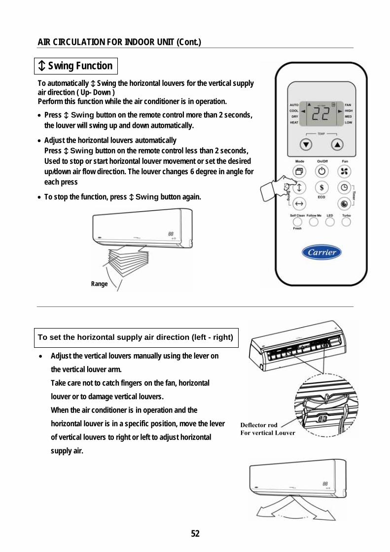
↕ Swing Function To automatically ↕ Swing the horizontal louvers for the vertical supply air direction ( Up- Down ) Perform this function while the air conditioner is in operation. • Press ↕ Swing button on the remote control more than 2 seconds,
the louver will swing up and down automatically.
• Adjust the horizontal louvers automatically Press ↕ Swing button on the remote control less than 2 seconds, Used to stop or start horizontal louver movement or set the desired up/down air flow direction. The louver changes 6 degree in angle for each press
• To stop the function, press ↕ Swing button again.
To set the horizontal supply air direction (left - right)
• Adjust the vertical louvers manually using the lever on the vertical louver arm. Take care not to catch fingers on the fan, horizontal louver or to damage vertical louvers. When the air conditioner is in operation and the horizontal louver is in a specific position, move the lever of vertical louvers to right or left to adjust horizontal supply air.
Range
Deflector rod For vertical Louver
53
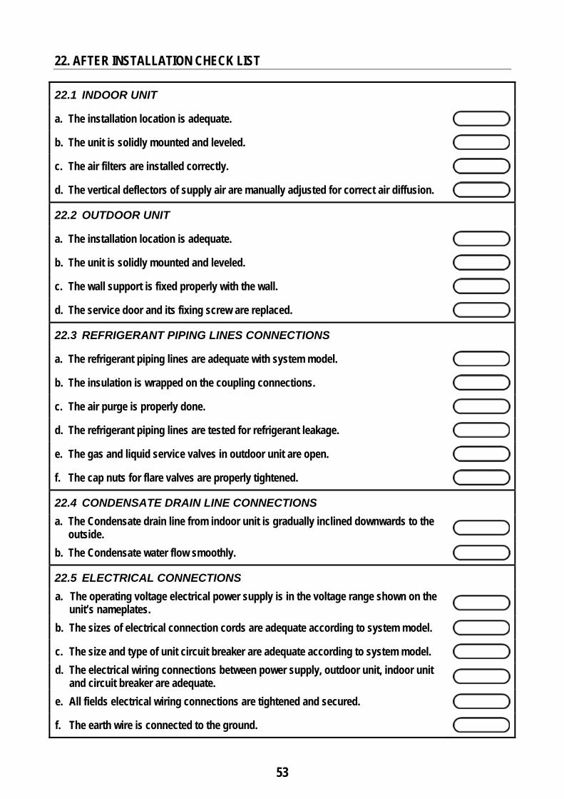
22. AFTER INSTALLATION CHECK LIST
22.1 INDOOR UNIT
a. The installation location is adequate.
b. The unit is solidly mounted and leveled.
c. The air filters are installed correctly.
d. The vertical deflectors of supply air are manually adjusted for correct air diffusion.
22.2 OUTDOOR UNIT
a. The installation location is adequate.
b. The unit is solidly mounted and leveled.
c. The wall support is fixed properly with the wall.
d. The service door and its fixing screw are replaced.
22.3 REFRIGERANT PIPING LINES CONNECTIONS
a. The refrigerant piping lines are adequate with system model.
b. The insulation is wrapped on the coupling connections.
c. The air purge is properly done.
d. The refrigerant piping lines are tested for refrigerant leakage.
e. The gas and liquid service valves in outdoor unit are open.
f. The cap nuts for flare valves are properly tightened.
22.4 CONDENSATE DRAIN LINE CONNECTIONS a. The Condensate drain line from indoor unit is gradually inclined downwards to the
outside.
b. The Condensate water flow smoothly.
22.5 ELECTRICAL CONNECTIONS a. The operating voltage electrical power supply is in the voltage range shown on the
unit’s nameplates.
b. The sizes of electrical connection cords are adequate according to system model.
c. The size and type of unit circuit breaker are adequate according to system model. d. The electrical wiring connections between power supply, outdoor unit, indoor unit
and circuit breaker are adequate.
e. All fields electrical wiring connections are tightened and secured.
f. The earth wire is connected to the ground.
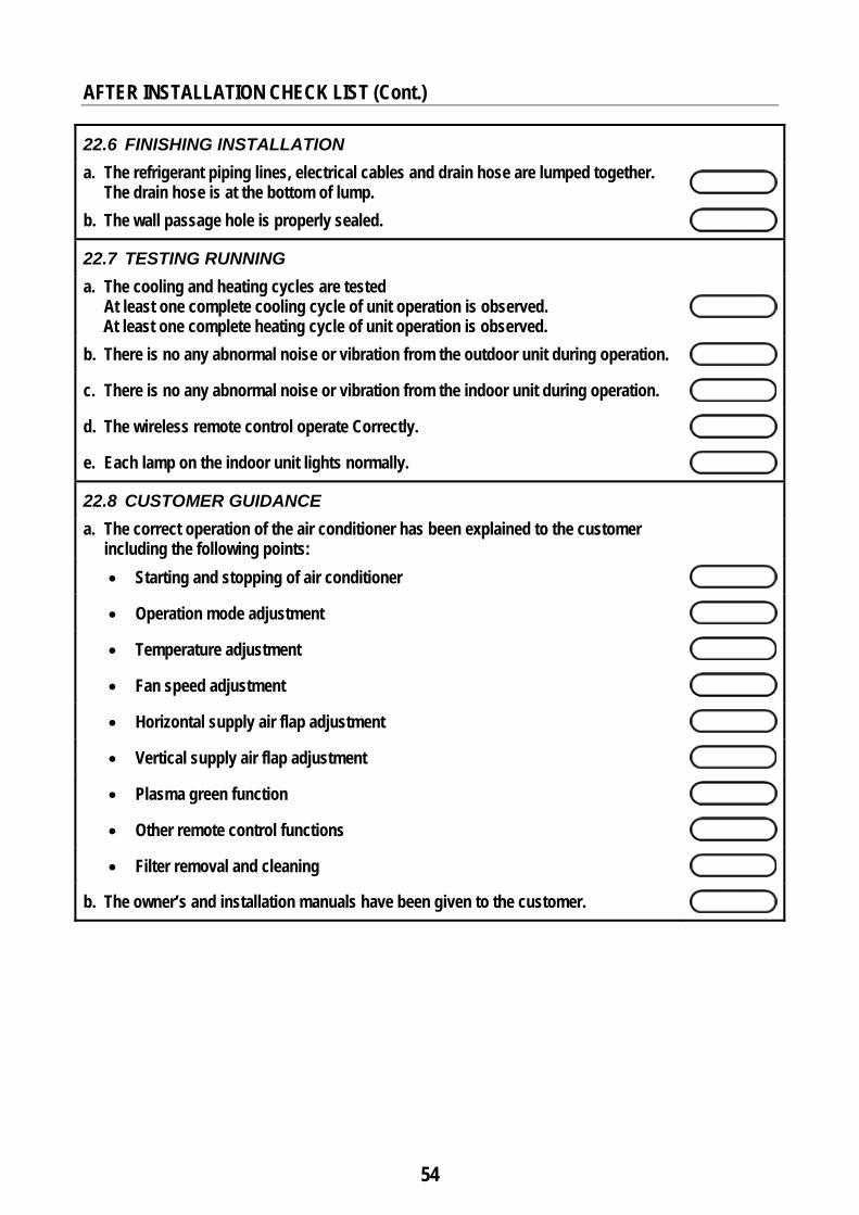
54
AFTER INSTALLATION CHECK LIST (Cont.)
22.6 FINISHING INSTALLATION a. The refrigerant piping lines, electrical cables and drain hose are lumped together.
The drain hose is at the bottom of lump.
b. The wall passage hole is properly sealed.
22.7 TESTING RUNNING a. The cooling and heating cycles are tested
At least one complete cooling cycle of unit operation is observed. At least one complete heating cycle of unit operation is observed.
b. There is no any abnormal noise or vibration from the outdoor unit during operation.
c. There is no any abnormal noise or vibration from the indoor unit during operation.
d. The wireless remote control operate Correctly.
e. Each lamp on the indoor unit lights normally.
22.8 CUSTOMER GUIDANCE a. The correct operation of the air conditioner has been explained to the customer
including the following points:
• Starting and stopping of air conditioner
• Operation mode adjustment
• Temperature adjustment
• Fan speed adjustment
• Horizontal supply air flap adjustment
• Vertical supply air flap adjustment
• Plasma green function
• Other remote control functions
• Filter removal and cleaning
b. The owner’s and installation manuals have been given to the customer.
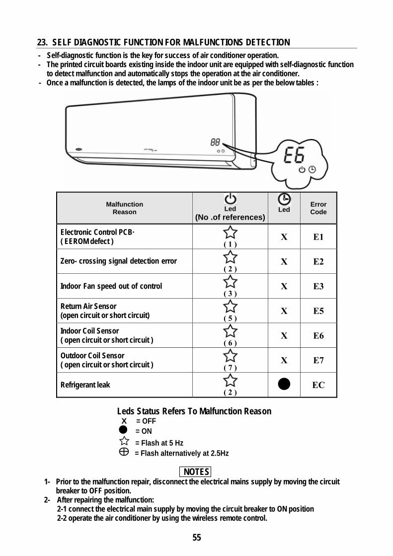
55
23. SELF DIAGNOSTIC FUNCTION FOR MALFUNCTIONS DETECTION
- Self-diagnostic function is the key for success of air conditioner operation. - The printed circuit boards existing inside the indoor unit are equipped with self-diagnostic function
to detect malfunction and automatically stops the operation at the air conditioner. - Once a malfunction is detected, the lamps of the indoor unit be as per the below tables :
Error Code
Led
Led
(No .of references)Malfunction
Reason
E1 X ( 1 )
Electronic Control PCB· ( EEROM defect )
E2 X ( 2 )
Zero-crossing signal detection error
E3 X ( 3 )
Indoor Fan speed out of control
E5 X ( 5 )
Return Air Sensor (open circuit or short circuit)
E6 X ( 6 )
Indoor Coil Sensor ( open circuit or short circuit )
E7 X ( 7 )
Outdoor Coil Sensor ( open circuit or short circuit )
EC
( 2 )
Refrigerant leak
Leds Status Refers To Malfunction Reason X = OFF = ON = Flash at 5 Hz = Flash alternatively at 2.5Hz
NOTES
1- Prior to the malfunction repair, disconnect the electrical mains supply by moving the circuit breaker to OFF position.
2- After repairing the malfunction: 2-1 connect the electrical main supply by moving the circuit breaker to ON position 2-2 operate the air conditioner by using the wireless remote control.
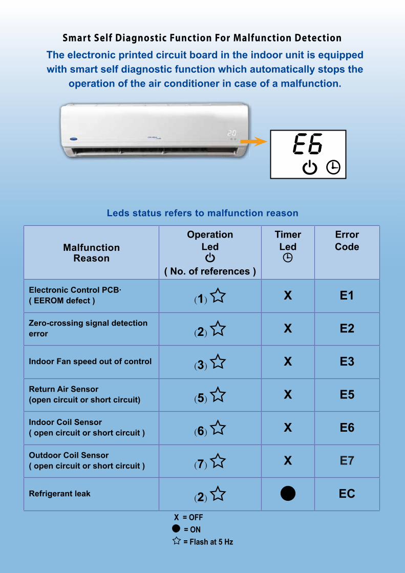
Smart Self Diagnostic Function For Malfunction Detection
The electronic printed circuit board in the indoor unit is equipped with smart self diagnostic function which automatically stops the
operation of the air conditioner in case of a malfunction.
X = OFF = ON = Flash at 5 Hz
Leds status refers to malfunction reason
MalfunctionReason
OperationLed
( No. of references )
TimerLed
ErrorCode
Electronic Control PCB·( EEROM defect ) (1) X E1
Zero-crossing signal detection error (2) X E2
Indoor Fan speed out of control (3) X E3
Return Air Sensor(open circuit or short circuit) (5) X E5
Indoor Coil Sensor( open circuit or short circuit ) (6) X E6
Outdoor Coil Sensor( open circuit or short circuit ) (7) X E7
Refrigerant leak (2) EC
Recommended


![COMMERCIAL AIR CONDITIONERS 2013 - Miraco CarrierMCAC-2012-32]R22... · COMMERCIAL AIR CONDITIONERS R22 Tropical Split Commercial A/C 50Hz 2013 Commercial Air Conditioner Business](https://img.pdfslide.us/doc/110x75/5acc2a417f8b9a93268c2cfe/commercial-air-conditioners-2013-miraco-mcac-2012-32r22commercial-air-conditioners.jpg)