Please note this is a condensed catalog. For a complete version, contact Velan directly.

2
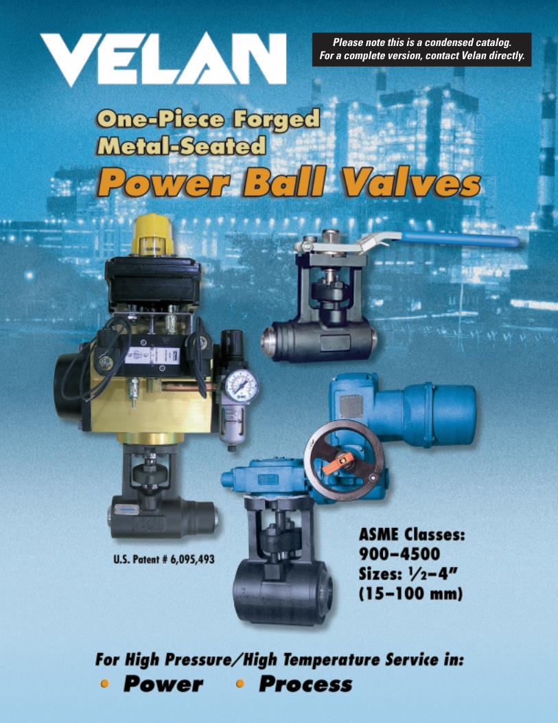
VELAN VALVES IN POWER
11/2” (40 mm) Power Ball Valves in steam trap isolation at amajor British power plant. Switching to Velan Power Ball Valvesoffered a low torque, easy to operate solution.
Velan Power BallValve in high
pressure steamservice.
Attemperator Isolation ValvesBoiler Feedwater Pump RecirculationBottom BlowdownBypass Injector IsolationCogeneration (Emergency ShutdownSystem)Condensate Drain Lines Above/BelowTurbine Throttle ValvesFeedwater Heater IsolationFeedwater Heater DrainFeedwater Heater Loop DrainIsolation Turbine DrainsLow Pressure Turbine DrainsMain Steam Drum VentsMain Steam Extraction Bleed ValvesNuclearPressurized Fluidized Beds (PFB)Reheat IsolationSteam Trap IsolationSeal Steam IsolationSteam (Saturated/Superheated)
POWER BALL VALVES IN POWER GENERATION
With an installed base covering over 300 nuclearpower plants and over 2,000 thermal power plants,and valves with over forty years of uninterruptednuclear service, Velan is a market leader in powerindustry valves.
Velan's Power Ball Valve joins a long list of provenproducts for power, including our forged boltedbonnet and pressure seal valves, bonnetless y-pattern globe valves, cast steel valves, smallforged valves, and bimetallic steam traps. As amatter of fact, most of the different types of valvesthat Velan designs and manufactures (see backcover) have been sold into power plant applications.

5
ASSURES RELIABILITY AND LONG SERVICE LIFE
“0” LEAKAGE SEALING INTEGRITYEvery Power Ball Valve meets the testing requirements of ASMEB16.34. Each valve is subjected to hydrostatic shell and seatleakage tests in accordance with MSS-SP-61. Velan imposes azero leakage criteria, which exceeds the standard.
The Inconel ball and seat (typical hardness of Rc. 68) arechrome carbide coated by specially developed high velocitycoating techniques that exceed the bond strength achieved bythe standard HVOF process and are mate-lapped to perfection,ensuring resistance to wear and galling and long service life.
LOCKING DEVICE STANDARD
ONE-PIECE FORGED BODY
Offers unique advantages against competition's two-piece bolted ball valves.
External Leak Paths are EliminatedRugged/durable, one-piece, forged body designs in bothvalves eliminate the potential for body-to-bonnet joint leakage.
Add to that Velan's unparalleled performance in stem-packing-packing chamber sealing, and you have a recipe for trouble-free vent and drain service in your plant. Competitive valvemanufacturers use fabricated, welded-on or bolted-on yokeswhich are far inferior in terms of meeting design stresses.
TRUE QUARTER TURN VALVE – LOW TORQUE No gear actuators required for valves 1/2–2" (15–50 mm) due to a fullyguided stem and life-lubricated thrust bearing which reduce torque (see Table of Torques page 8).
INCONEL 718 LOAD RINGMaintains tight contact between seats and ball protectingseats in an open and closed position. Accommodates hightemperature transients, allowing thermal expansion.
Dimensions for the actuator attachments are as follows: • Sizes 1/2–11/2” (15–40 mm): F05 (includes 11/2” 900–2800)• Sizes 11/2–2” (40–50 mm): F10 (includes 11/2” 4500)• Sizes 21/2–4” (65–100 mm): F12
Valve stems are supplied standard with flat head(double-D) type drive. This allows for manual leveroperated valves to be retrofitted with an actuator in thefield. Square head drive is also available upon request.
For high temperature service, Velan can supply a heat gasket, placed between the valve and actuator,and/or actuators with high temperature trim, to protectthe operator from heat transferred through the valve.
For specific questions relating to automation, especially with regards to top-works, torque require-ments and temperature limitations, please contactVelan’s Metal-Seated Quarter Turn MarketingDepartment.
Y-Pattern & Power Ball Valve Tandem
Capitalizing on the proven design features andsuperior performance of our Power Ball and y-pattern globe valves, Velan introduces ourinnovative POWER-COMBO, matching the Power Ball (as the shut-off valve) with our forged,one-piece y-pattern (as the flow on/off valve) for vent and drain service in high pressure/temperature systems.
This tandem provides for a higher measure ofsystem integrity assurance, while extending theservice life of the valves in this tough application,and can be pre-fabricated at the factory, at ourauthorized repair facilities (Simply provide pipematerial, schedule and applicable dimensions at timeof request for quotation), or at the site by the owner.
Socket Weld 1/2– 21/2“ (15–65 mm) Butt Weld 1/2– 4“ (15–100 mm)ASME Class 900–4500
4
SUPERIOR DESIGN AND UNIQUE CONSTRUCTION
Velan’s Power Ball Valve is a highly advanced,patented, forged, one-piece metal-seated valvedesigned for high pressure/high temperatureapplications in the power generation and process industries.
DOUBLE STEM BLOW OUT PROTECTIONHigh stem thrust from internal pressure is borne byexternal, life-lubricated bearing on stem shoulder. The split yoke bushing cannot be removed in-line.Secondary protection with stem shoulder against splitgland bushing. Design precludes loading the stem to the point where it can push the ball through the seat.
INTEGRAL ISO MOUNTING PAD FOR AUTOMATION
Allows for direct mount of actuator to valvewithout bolting/welding on required mountingbracket. Fully guided oversized stem preventsmisalignment between the ball and actuator.
EMISSION FREE VALVEAn advanced packing chamber design with atwo-piece self-adjusting gland bushing andlive-loading provide long lasting, maintenance-free, stem packing tightness.
HANDLE-STEM CONNECTIONADJUSTABLE FOR WEAR
ISOLATED BODY CAVITYBall and seats are in full contact all the time, isolating the body cavity from flow to prevent build-up of solids.
SEAL WELDED DOWNSTREAM SEAT High temperatures/pressures/flow rates are handled better by downstream seat anchored in place by seal weld.
RUGGED, FULLY GUIDED ONE-PIECE STEMStem material is Gr. A638-660, a super alloywhich retains 92% of strength at 1200˚F (650°C). Bottom and top are fully guided with bushings.This (no wobbling) prevents side loads whichcan damage packing and cause leakage.
boiler
Power Ball - quick acting valve
y-pattern- slow acting valve
VELAN POWER-COMBO FOR VENTS AND DRAINS
U.S. Patent # 6,095,493
DIRECT MOUNT ISO MOUNTING FLANGE
The unique one-piece forged body construction of thePower Ball Valve includes an integral mounting flangefor automation. Both the mounting pad and valve stemdimensions meet ISO-5211 standards, which allow forthe direct-mount of actuators without the need foradditional brackets and/or drive couplings. In addition to significant cost savings, a direct-drive actuator ensures the best possible alignment between the ball and operator. Note: Configuration of the POWER-COMBO is at the discretion of the owners/user.
The Power Ball Valve can be supplied with a gear and handwheel, thus meeting the requirements for a slow acting valve.

PART MATERIALS FOR CLASS 4500
Body A182 F22 Cl. 3, A182 F91
STANDARD MATERIALS PART MATERIALS FOR CLASSES 900, 1690, 2800
Body A105, A182 F22 Cl. 3, A182 F91, A182 F316
6
� Valve parts can only be disassembled for service outside the line after removal from pipe. This provides safety in high pressureoperation.
� The ball in closed position and the upstream seatmust be removed first to allow removal of all other parts.
� The gland bushing and yoke bushing are split to facilitate disassembly.
� See Power Ball Valve Maintenance Manual (PBVM).
REMOVAL OF PARTS
DESIGNED FOR LONG SERVICE
Please note this is a condensed catalog. For a complete version, contact Velan directly.
Please note this is a condensed catalog. For a complete version, contact Velan directly.
7
Sizein Class
A B ∅F G Lmm SW BW BWN
1/2" 900– 5.00 5.00 6.50 6.76 0.865 0.38 –15 2800 127 127 165 172 22.0 10 –1/2"
45005.00 5.00 6.50 6.76 0.865 0.38 –
15 127 127 165 172 22.0 10 –3/4" 900– 5.00 5.00 6.50 6.76 1.075 0.50 –20 2800 127 127 165 172 27.3 13 –3/4"
45005.00 5.00 6.50 6.74 1.075 0.50 –
20 127 127 165 171 27.3 13 –1" 900– 5.00 5.00 6.50 6.76 1.340 0.50 –25 2800 127 127 165 172 34.0 13 –1"
45005.25 5.25 6.75 6.74 1.340 0.50 –
25 133 133 171 171 34.0 13 –11/4" 900– 5.25 5.25 6.75 6.76 1.685 0.50 –32 2800 133 133 171 172 42.8 13 –
11/4"4500
5.25 5.25 6.75 6.74 1.685 0.50 –32 133 133 171 171 42.8 13 –
11/2" 900– 5.25 5.25 6.75 6.76 1.925 0.50 –40 2800 133 133 171 172 48.9 13 –
11/2"4500
7.50 7.50 9.50 10.63 1.925 0.50 –40 191 191 241 270 48.9 13 –2" 900– 7.50 7.50 9.50 10.63 2.416 0.62 –50 2800 191 191 241 270 61.4 16 –2"
45007.50 7.50 9.50 10.63 2.416 0.62 –
50 191 191 241 270 61.4 16 –21/2" 900– 10.00 10.00 12.50 – 2.919 0.62 13.4365 2800 254 254 318 – 74.1 16 341
21/2"4500
10.00 10.00 12.50 – 2.919 0.62 13.4365 254 254 318 – 74.1 16 3413" 900– 12.50 10.00 12.50 – – – 13.4380 2800 318 254 318 – – – 3413"
450012.50 10.00 12.50 – – – 13.43
80 318 254 318 – – – 3414" 900– – 10.00 – – – – 13.43
100 2800 – 254 – – – – 3414"
4500– 10.00 – – – – 13.43
100 – 254 – – – – 341
NPS Pipe BW w/Nipple in (mm)in Sch.
∅W ∅X Y Z(mm) number 900-2800 4500
1/2" 80 0.840 0.546 (13.87) 0.22 (5.59) 0.29 (7.37)160 � � 0.464 (11.79) 0.28 (7.11) 0.38 (9.65)
(15) XXS(1) (21.3) 0.252 (6.40) 0.44 (11.18) 0.59 (14.99)3/4" 80 1.050 0.742 (18.85) 0.23 (5.84) 0.31 (7.87)
160 � � 0.612 (15.55) 0.33 (8.38) 0.44 (11.18)(20) XXS(1) (26.7) 0.434 (11.02) 0.46 (11.68) 0.62 (15.75)
1" 80 1.315 0.957 (24.31) 0.27 (6.86) 0.36 (9.14)160 � � 0.815 (20.70) 0.38 (9.65) 0.50 (12.70)
(25) XXS(1) (33.4) 0.599 (15.22) 0.54 (13.72) 0.72 (18.29)
11/4" 80– – 1.660 1.278 (32.46) 0.29 (7.37) 0.38 (9.65)
160 1.160 (29.46) 0.38 (9.65) 0.50 (12.70)(32) XXS(1) � �
(42.2) 0.896 (22.76) 0.57 (14.48) 0.76 (19.30)
11/2" 80– 1.900 1.500 (38.10) 0.30 (7.62) 0.40 (10.16)
160 � 1.337 (33.96) 0.42 (10.67) 0.56 (14.22)(40) XXS �
(48.3) 1.100 (27.94) 0.60 (15.24) 0.80 (20.32)
2" 80 – – 2.357 1.939 (49.25) 0.33 (8.38) 0.44 (11.18)160
� �1.687 (42.85) 0.52 (13.21) 0.69 (17.53)
(50) XXS(1) (60.3) 1.503 (38.18) 0.65 (16.51) 0.87 (22.10)
21/2" 80 2.875 2.323 (59.00) 0.41 (10.41) 0.55 (13.97)160 � � 2.125 (53.98) 0.56 (14.22) 0.75 (19.05)
(65) XXS(1) (73.0) 1.771 (44.98) 0.83 (21.08) 1.10 (27.94)
3" 80 – – 3.500 2.900 (73.66) 0.45 (11.43) 0.60 (15.24)160
� �2.624 (66.65) 0.66 (16.76) 0.88 (22.35)
(80) XXS (88.9) 2.300 (58.42) 0.90 (22.86) 1.20 (30.48)
4" 80 4.500 3.826 (97.18) 0.51 (12.95) 0.67 (17.02)160 – – 3.438 (87.33) 0.80 (20.32) 1.06 (26.92)
(100) XXS(1) (114.3) 3.152 (80.06) 1.01 (25.65) 1.35 (34.29)
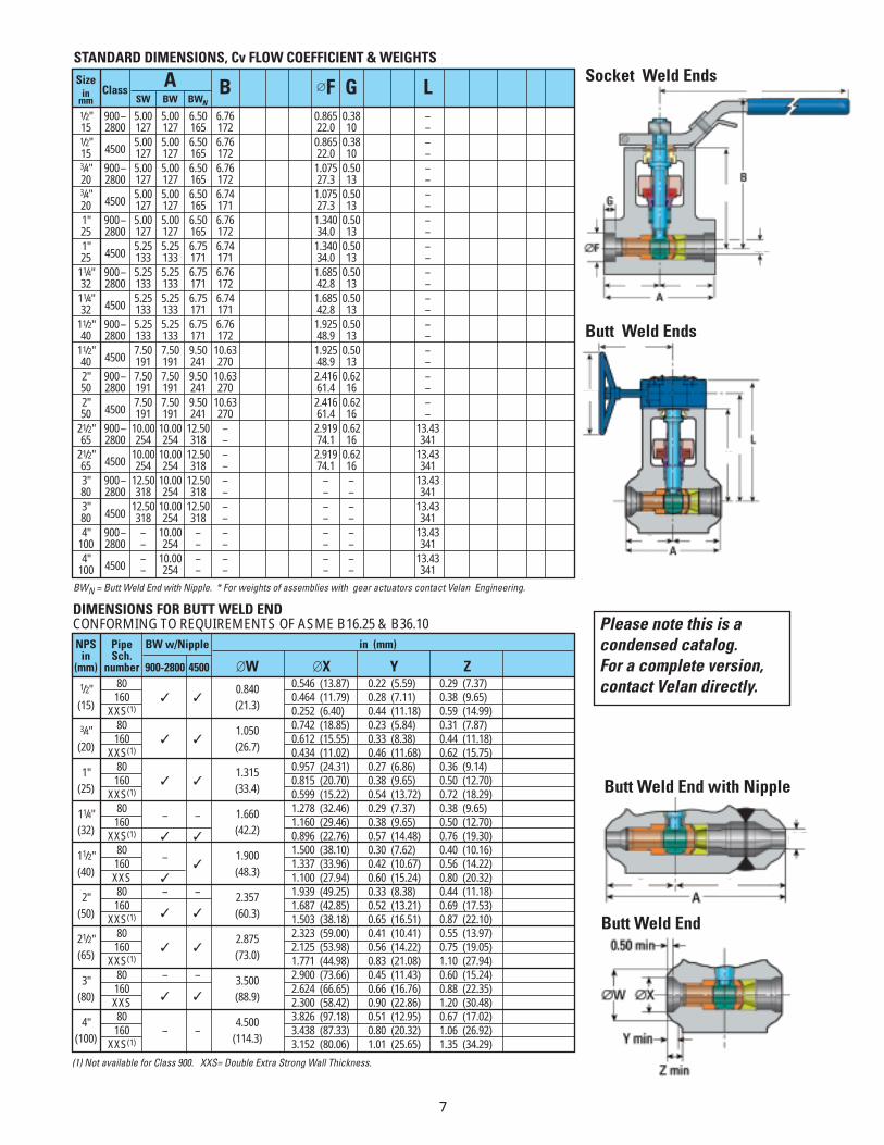
STANDARD DIMENSIONS, Cv FLOW COEFFICIENT & WEIGHTS
DIMENSIONS FOR BUTT WELD END CONFORMING TO REQUIREMENTS OF ASME B16.25 & B36.10
(1) Not available for Class 900. XXS= Double Extra Strong Wall Thickness.
Butt Weld End with Nipple
Butt Weld End
Socket Weld Ends
Butt Weld Ends
BWN = Butt Weld End with Nipple. * For weights of assemblies with gear actuators contact Velan Engineering.
Please note this is acondensed catalog. For a complete version,contact Velan directly.

9
ACTUATORS
GEAR ACTUATORSVelan worm gear actuators provide reliable anddependable manual operation for 21/2–4” (65–100 mm)Power Ball Valves. The gear is designed to operate in the range of 90°, ±5° and is equipped with angular dialindicator. VW worm gear actuators feature a gearsegment and a rigid, reversible shaft with integral worm. The gear actuators comply with ISO 5211 and aresuitable for high temperature service.
AIR & ELECTRIC ACTUATORSVelan supplies high quality pneumatic rack & pinion andscotch yoke actuators for 1/2–4“ (15–100 mm) Power BallValves. All actuators are totally enclosed. Externaladjustment stops provide accurate adjustment for closingand opening positions. All moving parts are permanentlylubricated. Actuators can be installed in the field, although it is preferable that they be installed and tested in the factory.
AIR ACTUATOR ELECTRIC ACTUATORGEAR ACTUATOR
HOW TO ORDER
SIZE OFCONNECTION PORTCLASS BODY
MATERIALTRIM
MATERIAL
BALL/SEAT STEM
TYPE
A B C D E
COATINGS
F G
TYPE OFCONNECTION
W 0 5 — 9 2 Q 0 2 — F R B AEXAMPLE: 1” 2800 Class socket weld A105 ball valve
SPECIALSERVICE OR
DESIGN
H
— —
The figure numbers shown on this key are designed to cover essential features of Velan valves. Please use figure numbers to ensure promptand accurate processing of your order. A detailed description must accompany any special orders.
I
TYPE OF CONNECTIONB – Butt weld W– Socket weld
SIZE OF CONNECTIONCustomers have the choice of specifying valve size aspart of the valve figure (“B”) using the numbersbelow, or indicating valve size separately.Examples:1”W-92Q02-FRBA (valve size shown separately)W05-92Q02-FRBA (valve size in figure number)03 – 1⁄2” (15 mm) 08 – 2” (50 mm)04 – 3⁄4” (20 mm) 09 – 21⁄2” (65 mm)05 – 1” (25 mm) 10 – 3” (80 mm)06 – 11⁄4” (32 mm) 12 – 4” (100 mm)07 – 11⁄2” (40 mm)
B
A BALL & SEAT MATERIALF – Inconel 718
STEM MATERIALR – A638 Gr. 660 (Gr. 616 may be substituted
for 900–2800 pressure classes)
COATINGS (Ball and Seats unless noted)
B – Chrome Carbide G – Stellite
SPECIAL SERVICE OR DESIGN
A – Standard
I
H
GPRESSURE RATING For threaded or socket weld use model number:5 – 4500 8 – 1690 7 – 900 9 – 2800
PORT2 – Reduced port
TYPE
Q – One-Piece Forged Metal-Seated Power Ball
BODY MATERIAL02 – A105 10 – S/S F316H/F316(1) 34 – F9106 – F22 13 – F316
F
E
D
C
(1) Material Code “10” F316H/F316 has a minimum carbon content of 0.04 and is to be used if temperatures are over 1000˚F (538˚C). Forged F316, Material Code “13”, is not suitable for temperatures above 1000˚F (538˚C) as it is dual certified (F316/F316L).
Recommended