PINNACLE®
PRIMARY VENTILATION SYSTEM
TECHNICAL GUIDE
AIR TREATMENT
AIR COMFORT
PINNACLE
ii
TECHNICAL GUIDE
PINNACLE®
TABLE OF CONTENTS
© SEMCO Incorporated 1999-2015. All rights reserved.
The information in this technical guide is furnished for informational use only, is subject to change without notice, and should not be construed as a commitment by SEMCO. SEMCO assumes no responsibility for any errors that may appear in this technical guide.
No part of this publication may be reproduced, stored in a retrieval system or transmitted, in any form or by any means, electronic, mechanical, recording, or otherwise, without the prior written permission of SEMCO.
U.S. patented technology: 5,401,706 ; 5,496,397 ; 6,199,388EXCLU-SIEVE, Pinnacle, and SEMCO are registered trademarks of SEMCO LLC.
Overview .................................................................................................................. 1Current Design Practices................................................................................... 2Background of Pinnacle® Technology ............................................................ 2The Pinnacle® System ........................................................................................ 3How it Works .........................................................................................................4Important Advantages of the Pinnacle® System ......................................... 8School Application ............................................................................................... 9Benefits During Unoccupied Periods ............................................................ 10Benefits During Heating Season ..................................................................... 11Conclusion............................................................................................................. 11Selection Procedure ...........................................................................................12Unit Weights and Dimensions ........................................................................13 PVS 3 - 43 .....................................................................................................13 PVSH 3 - 28 ..................................................................................................14 PVSH 35 - 43 ................................................................................................15Mounting Details, Curb Support ..................................................................... 16Mounting Details, Grid or Pad Support .........................................................17Electrical Data ....................................................................................................18Electrical Schematic ......................................................................................... 19Component Pressure Drop Tables .................................................................21Fan Data Tables ................................................................................................22Coil Data Tables .................................................................................................28Sample Specifications ......................................................................................32Equipment Summary .........................................................................................39
1
TECHNICAL GUIDE
PINNACLE®
OVERVIEWEnergy efficient design and indoor air quality are the two challenges facing mechanical engineers today in the field of Heating, Ventilating and Air Conditioning (HVAC). To minimize the loss of energy, building envelopes have been made more energy efficient. This reduces the cost associated with cooling or heating the building. By tightening the building envelopes, the amount of outside air entering the building is reduced. However, that outside air is needed to remove the air contaminants generated indoors. Flushing these pollutants from the indoors to the outdoors has been the most effective way of reducing indoor air contaminants to acceptable levels.
The HVAC industry has responded to these indoor air quality (IAQ) concerns through its professional organization, The American Society of Heating and Refrigerating and Air Conditioning Engineers (ASHRAE). ASHRAE IAQ Standard 62, entitled “Ventilation for Acceptable Indoor Air Quality,” emphasizes the need for continuous outdoor air ventilation as well as the importance of maintaining indoor humidity levels. This standard has now been integrated, in some fashion, into each of the major building codes used throughout the United States.
Most people are aware that outdoor air pollution can damage their health, but many do not know that indoor air pollution can also cause harm. Environmental Protection Agency (EPA) studies of human exposure to air pollutants indicate that indoor levels of pollutants may be 2-5 times, and occasionally more than 100 times, higher than outdoor levels. These levels of indoor air pollutants are of particular concern because it is estimated that most people spend about 90% of their time indoors.
Studies have found that the quality of indoor air has been linked to many illnesses (sick building syndrome and building related illnesses), and has been shown to have a direct impact on worker and student productivity and comfort. New research strongly suggests that indoor humidity levels have a far greater impact on the health of building occupants than previously suspected. For example, microbial activity (e.g., mold and fungus), which increases at higher indoor humidity levels, has been shown to emit harmful organic compounds. Childhood asthma is now suspected by some researchers to be linked to microbial activity.
In addition to direct health effects, the odors associated with microbial activity are often cited as a primary reason why indoor air quality is considered unacceptable to occupants. When odors are encountered in a building, building managers often respond by increasing outdoor air quantities in an attempt to eliminate odors. This intensifies the problem because increasing outdoor air quantities often results in higher indoor humidity levels, which, in turn, fosters continued microbial activity.
2
TECHNICAL GUIDE
PINNACLE®
Facilities with high occupancy rates or elevated levels of indoor contaminants, such as schools, hospitals, nursing homes, and many offices, require large amounts of outdoor air. This presents a significant HVAC design challenge. This challenge is further exacerbated in hot and humid climates, due to the high humidity levels and large number of partial-load cooling hours. Maintaining relative humidities at levels recommended by the ASHRAE Standard 62 is difficult and costly if conventional HVAC approaches are used for such facilities.
Conventional packaged equipment is designed to accommodate approximately only 15 to 20% outdoor air on an intermittent basis. If the equipment is applied to provide higher outdoor air quantities on a continuous basis, as called for by ASHRAE Standard 62, unacceptably high space humidities can result for extended periods of time.
At part load conditions, e.g., on days when the temperature is moderate but the humidity is high, a packaged HVAC unit will quickly bring the space to the desired set point temperature, then cycle off. Generally,
no outdoor air is brought into a conditioned space as long as the thermostat does not call for cooling. Since there is no humidity control exercised, the indoor humidity increases until the sensible load in the space causes the thermostat to call for cooling. By this time, the mixed air condition supplied to the coil is elevated in humidity. This results in a high dew point temperature leaving the cooling coil.
The space temperature is maintained but humidity control is lost, resulting in elevated space humidity conditions, which promote microbial growth and other moisture related IAQ problems.
Given that all of the major building codes now require compliance with the ASHRAE Standard 62, that data supporting the need for improved humidity control is available and that 80-90% of all HVAC sold in the U.S. each year are conventional packaged units, effective solutions that will allow packaged equipment to accommodate more outdoor air on a continuous basis are needed. The solution is the Pinnacle® Primary Ventilation System.
BACKGROUND OF PINNACLE® TECHNOLOGY
CURRENT DESIGN PRACTICESSystems currently being employed to accommodate the new IAQ code requirements fall into two categories; traditional designs using a cool-and-reheat approach or more advanced, desiccant-based solutions. The cool-and-reheat method increases the cooling capacity to “over-cool” the outdoor air volume to the required humidity content, then reheat the “over-cooled” airstream to near room neutral temperature. This approach is perceived as the “lowest cost” solution and is therefore the most popular, yet the energy consumption is very high.
More advanced systems, such as those that include both active and passive desiccant based technology, provide far more energy efficient solutions. They typically require
only a third of the energy consumed by the cool-and reheat method. In the past, their size and first cost has limited there widespread acceptance in the marketplace.
There is, therefore, a significant need for a novel, compact system design which effectively controls the indoor space humidity while simultaneously providing high quantities of outdoor air in an energy-efficient and cost-effective manner. The benefit of such a system is greatly increased if that system can also provide preconditioned outdoor air to a space at humidity levels well below that possible with conventional cooling alone.
3
TECHNICAL GUIDE
PINNACLE®
The Pinnacle System economically provides high quantities of outdoor air and controls indoor humidity levels at the same time. It accomplishes this by dehumidifying the supply air to very low dew points in an energy efficient manner, without the use of a regeneration heating source. It continuously delivers the outdoor air to the occupied space while simultaneously controlling humidity levels at the conditions recommended by ASHRAE, even at part-load conditions. The Pinnacle system is capable of providing a very high degree of latent cooling using only a minimum amount of conventional cooling input.
The Pinnacle approach utilizes the strengths of passive total energy recovery, conventional cooling technology and a new class of desiccant product, the passive dehumidification wheel, to provide the best possible outdoor air preconditioning system.
The system is comprised of a supply fan, an exhaust fan, a total energy wheel, a cooling coil and a passive dehumidification wheel. The total energy wheel is used to precondition fresh air using the exhausted building air. The cooling coil and passive dehumidification wheel then work in concert to further treat this fresh air stream to produce room temperature air at a much reduced humidity level.
THE PINNACLE® SYSTEM
An Example of Pinnacle’s Capabilities:
A 10,000 cfm Pinnacle system can provide as much as 50 tons of latent load (68 tons of total load) with only an input of 32 tons of conventional cooling.
Using the conventional over-cooling approach would require 90 tons of cooling input and would require 15,000 cfm plus reheat energy.
4
TECHNICAL GUIDE
PINNACLE®
HOW IT WORKSThe key to providing the exceptional dehumidification capability provided by the Pinnacle system is the development of a new class of product, the passive dehumidification wheel. This wheel uses a desiccant material that is optimized to remove moisture from a saturated air stream without an active regeneration source.
The Pinnacle system can provide dry outdoor air in an extremely energy efficient manner. All the components, the refrigeration coil, the total energy recovery wheel, and the passive dehumidification wheel, are optimized to operate in their most efficient respective envelopes. The result is minimal cooling energy input and maximum latent cooling output. As importantly, by changing the rotational speed of the “passive” dehumidification wheel, the amount of dehumidification capacity and the amount of reheat energy available can be optimized to meet the requirements of varying space temperatures and humidities.
The Pinnacle system has the advantage over conventional HVAC systems of being able to respond to various combinations of temperature and humidity, including the conditions described above, in an energy efficient manner and while providing humidity levels well below that possible with other conventional approaches.
The Pinnacle system is able to respond to these varying conditions by modulating the rotational speed of the passive dehumidification wheel, and/or adjusting the energy input to the cooling coil. The rotational speed control may be adjusted so as to control the level of temperature and moisture exchanged by the passive dehumidification wheel. The cooling control may be adjusted so as to control the level of cooling and dehumidification provided by the cooling coil. The control system used for the Pinnacle system can be adjusted and optimized based upon the conditions in the space, providing various combinations of temperature and humidity, to maintain the desired, ideal indoor conditions.
For example, during times when the space humidity content is as desired but is too hot, the controlled space can be cooled by the Pinnacle system without substantially lowering the space humidity. To do so the Pinnacle control system would increase the cooling output and adjust the rotational speed of the passive dehumidification wheel to a predetermined range at which it would provide a minimal amount of reheat to the supply air stream.
When the space is too hot and too humid, the controlled space is cooled and dehumidified by increasing the output of the cooling coil, and optimizing the rotational speed of the passive dehumidification wheel so that the dehumidification provided is maximized while the reheat capacity is minimized.
When the space is too cold and too humid, the controlled space is dehumidified without being cooled, by increasing the cooling output of the cooling coil and adjusting the rotational speed of the passive dehumidification wheel to provide maximum dehumidification and maximum reheat.
And finally, when the space requires heating, the passive dehumidification wheel and the cooling coil are turned off. The total energy recovery wheel preheats and humidifies the incoming air. In many buildings, this is sufficient to allow the building to be heated by its internal loads.
5
TECHNICAL GUIDE
PINNACLE®
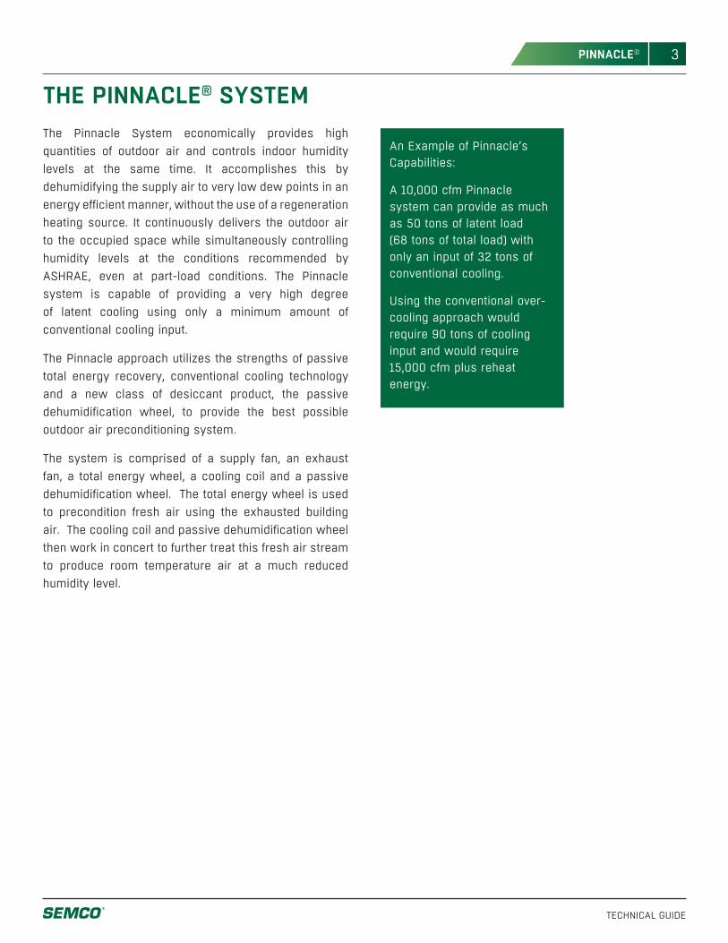
FIGURE 2. Schematic of the Pinnacle system operating at part-cooling load providing 56.9 tons of total cooling at a SHR of 0.16 using only 35.5 tons of refrigeration input. An equivalent conventional system would require 72.1 tons of cooling and 260 MBtuh of reheat to achieve the same leaving cooling coil temperature, yet without being able to deliver the same dew point of 42.3°F.
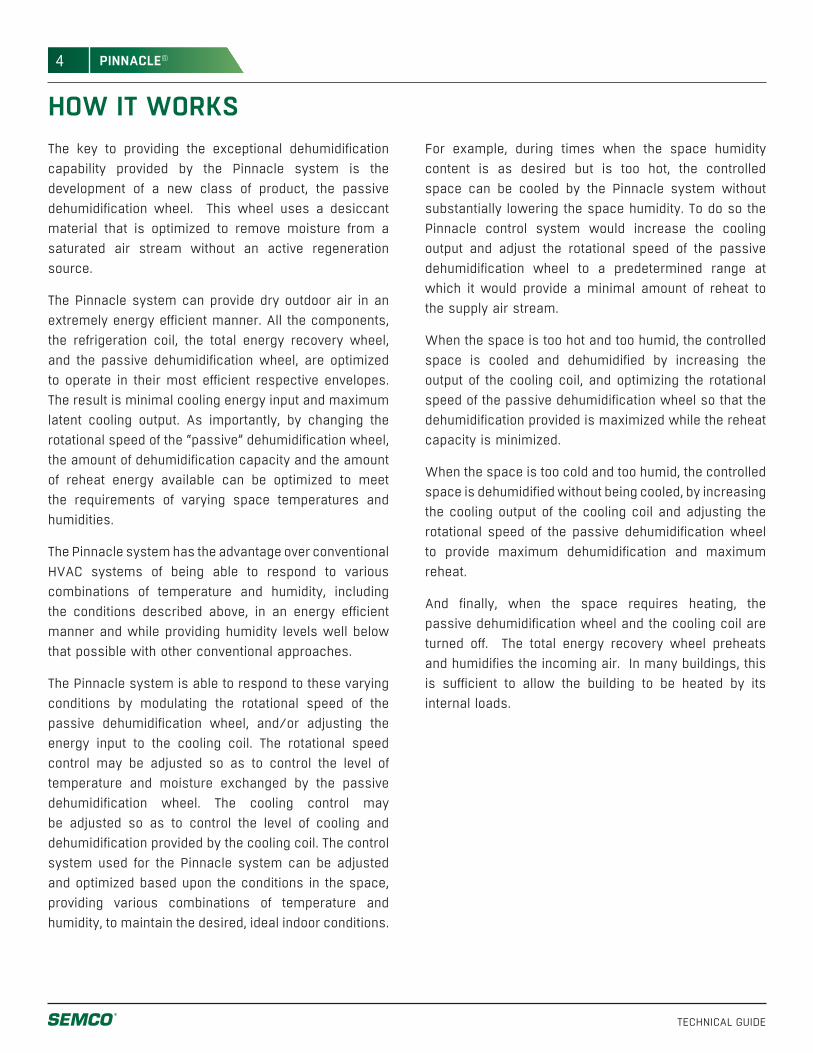
FIGURE 3. Schematic of the Pinnacle system operating in heating mode providing 740 MBtuh of energy and 178 MBtuh of humidification.
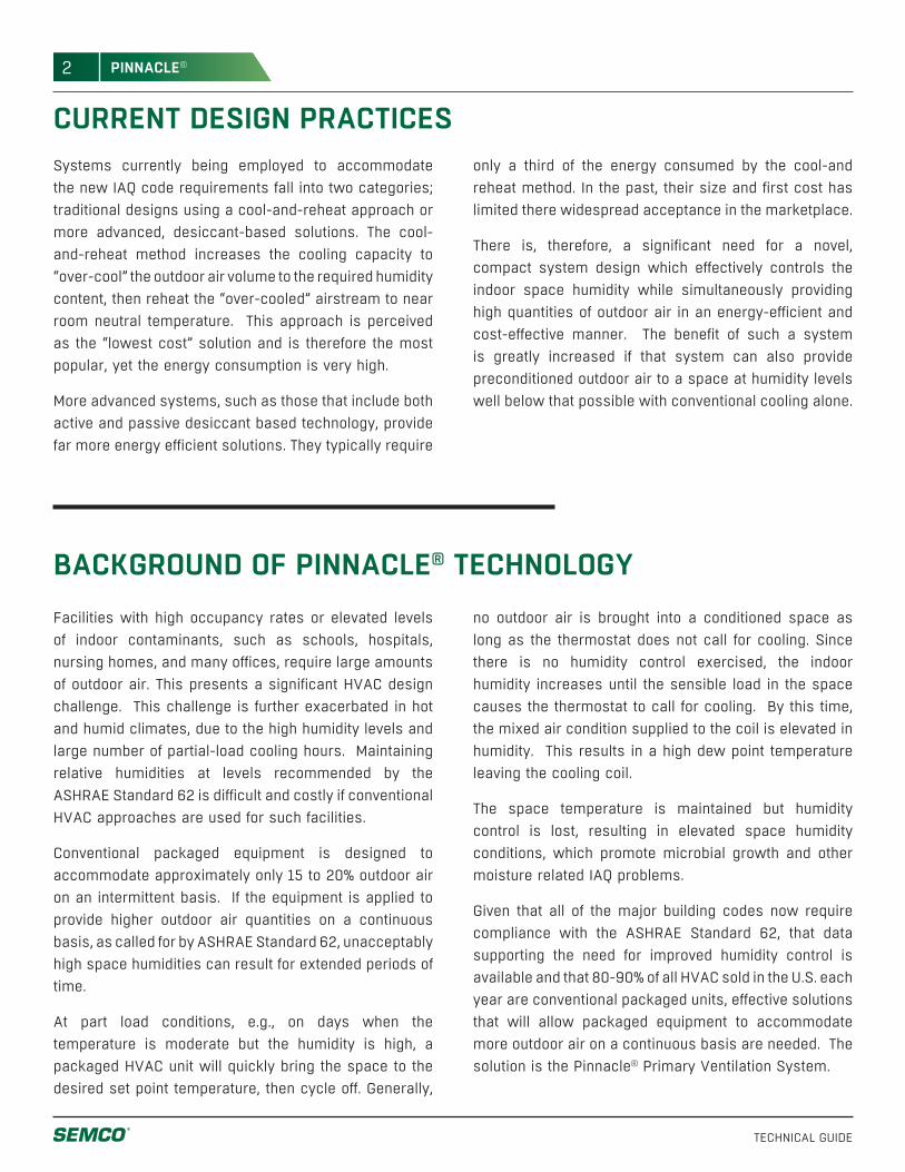
FIGURE 1. Schematic of the Pinnacle system operating at peak space latent load providing 88.5 tons of total cooling at a SHR of 0.27 using only 51.4 tons of refrigeration input. The dew point delivered to space is 38.9°F. A conventional system with the same leaving coil temperature will NOT deliver the same dewpoint. It would require 97.4 tons of refrigeration and 226 MBtuh to achieve the same leaving coil condition.
PassiveDehumidification
Wheel
TotalEnergyWheel
5663
6555
Dry Bulb Temperature in °F
Absolute Humidity in gr/lb
Return Air10,000 cfm
Supply Air10,000 cfm
Exhaust Air11,839 cfm
Outdoor Air11,839 cfm
CoolingCoil
7282
75110
73101
6873
7565
Passive Dehumidification
Wheel(OFF)
198
3518
7342
15 6
3163
6840
Dry Bulb Temperature in °F
Absolute Humidity in gr/lb
Cooling Coil
(OFF)
3116
TotalEnergyWheel
Exhaust Air11,714 cfm
Outdoor Air11,714 cfm
Return Air 10,000 cfm
Supply Air 10,000 cfm
Passive Dehumidification
Wheel
80120
6180
7365
85 130
5463
6848
Dry Bulb Temperature in °F
Absolute Humidity in gr/lb
Cooling Coil
6590
TotalEnergyWheel
Exhaust Air11,714 cfm
Outdoor Air11,714 cfm
Return Air 10,000 cfm
Supply Air 10,000 cfm
6
TECHNICAL GUIDE
PINNACLE®
The two most significant advantages offered by the Pinnacle system, when compared with the traditional over-cooling and reheat systems, are that (1) the dehumidification or latent capacity (e.g., dryness of the air provided to the controlled space) is significantly increased and (2) the energy efficiency is greatly improved.
The Pinnacle system has more latent capacity and higher energy efficiency than a desiccant-based cooling (DBC) or a dual-wheel energy recovery system (DWERS.)
For example, a DBC system processing outdoor air on a latent design day (85°F and 130 gr/lb) is limited to a supply air condition of approximately 60 grains with technology currently available. To reach this condition requires the equipment to be operated at very low face velocities (resulting in very large system space requirements) and regenerated at very high regeneration temperatures (large energy inputs.)
The DWERS and other conventional over-cooling reheat systems are limited by the humidity level of the air leaving the cooling coil. Since most conventional cooling systems have a practical limit of approximately 48°F leaving air temperature, the absolute humidity level obtainable from most conventional systems is about 50 grains per pound of moisture (gr/lb.)
As a result, the only commercially available way to dehumidify outdoor air below approximately 50 grains of moisture involves cooling the outdoor air below approximately 48°F, and requires expensive, non-standard cooling equipment with very deep cooling coils, complex controls with defrost cycles and significantly elevated kW/ton energy consumption (i.e. poor energy efficiency.)
The Pinnacle system can provide outdoor air at a humidity content of 40 gr/lb using standard cooling equipment. This results in a 90 gr/lb reduction at the typical latent design condition of 130 gr/lb, and can be designed and operated to provide air as dry as 35 gr/lb. Providing very dry air using conventional cooling equipment has many advantages including a significant reduction of energy consumption and thereby cost. With very dry air, lower air flow quantities can handle far more latent load.
For example, an office building could reduce energy consumption by operating its VAV air handling systems serving the space with dry cooling coils, allowing the supply air leaving temperature to be set by the controlled space sensible loads. This is possible if the outdoor air volume provided to the VAV air handling system is dehumidified enough to handle both the outdoor air and space latent loads. Because the percentage of outdoor air compared to the total supply air volume of a typical office designed to comply with ASHRAE Standard 62 may only be 15-20%, the outdoor air would need to be very dry if the entire internal latent load is to be handled by the outdoor air volume (dry cooling coils.)
IMPORTANT ADVANTAGES OF THE PINNACLE SYSTEM
7
TECHNICAL GUIDE
PINNACLE®
SCHOOL APPLICATIONThe Pinnacle system is particularly well suited for school classrooms where designers attempt to reduce project first cost by designing for only 7.5 cfm/student in lieu of the recommended 15 cfm/student.
For example, a typical school classroom today contains approximately 30 children. The sensible load associated with the lights, occupants, etc. is approximately 2 tons. The latent load associated with the occupants and infiltration is approximately 4.3 pounds per hour. Assuming the space is to be controlled at 75°F and 50% RH, a humidity content of 65 gr/lb is desired. If the latent load is to be handled with an outdoor air load of 450 cfm (based on 15 cfm/student) then the outdoor air must be delivered at 50 gr/lb (see sidebar for calculation.)
Now, if only 7.5 cfm/student is applied in lieu of the 15 cfm considered previously, then the required moisture differential doubles from the 15 gr/lb previously calculated to 30 gr/lb. Thus, to handle the latent load with 225 cfm of outdoor (7.5 cfm/student) the outdoor air must now be delivered at 35 gr/lb (= 65 gr/lb - 30 gr/lb). This level of dehumidification is generally NOT obtainable with conventional HVAC equipment.
The ability of the Pinnacle system to provide very dry outdoor air is also particularly advantageous where extreme indoor air humidity loads are encountered. For example, at least two times a day the doors to a school facility may be kept open for extended periods of time. Doors are frequently open in the morning when the students arrive and also when they leave for the day. It is very desirable to have excess/reserved latent capacity in the HVAC system in order to bring the indoor conditions back under control. This reserve capacity is particularly important during the morning because the outdoor air infiltrating the building during the cooling mode is typically cool and humid. As a result, little dehumidification will be accomplished by the conventional HVAC systems controlled by space temperature.
The humidity content of the supply air is calculated by dividing the pounds of latent load by the pounds of dry air (4.3 lb. moisture/hr divided by 2,025 lb. outdoor air/hour) to determine the required moisture differential required (in this case a differential of .0021 lb. moisture per lb. of dry air is required or 15 grains). By taking the desired space humidity content (65 grains) and subtracting the calculated moisture differential (15 grains) the required supply condition is calculated (50 grains).
8
TECHNICAL GUIDE
PINNACLE®
BENEFITS DURING UNOCCUPIED PERIODSAnother advantage offered by the Pinnacle system is its ability to control humidity levels in unoccupied facilities which can not be effectively accomplished with current preconditioning technologies.
During unoccupied times, as research has shown, the building materials (e.g., carpeting, furnishings, etc.) act as a moisture sponge as the humidity level rises. This rise in humidity is typical because many building operators reduce the capacity of or cycle off the HVAC system in an attempt to conserve energy. Because the sensible load in unoccupied buildings is minimal, controlling humidity can only be accomplished effectively if reheat is utilized after the air leaves the cooling coil. This reheat capability is seldom designed into projects or utilized if the capability exists.
The Pinnacle system can be operated to provide an effective solution to either “dry out” the humidity stored in the building materials or to provide humidity control during unoccupied periods. This is both practical and energy efficient because additional reheat is not required,
since it is provided by the passive dehumidification wheel.
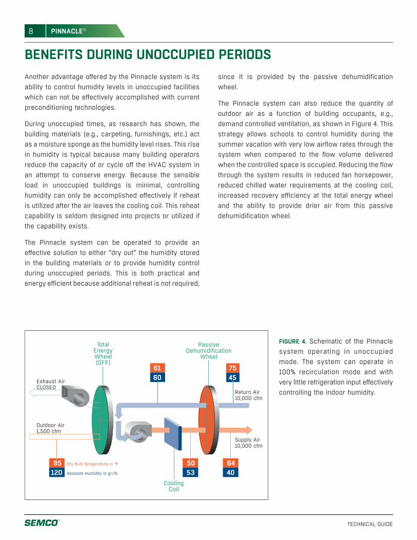
The Pinnacle system can also reduce the quantity of outdoor air as a function of building occupants, e.g., demand controlled ventilation, as shown in Figure 4. This strategy allows schools to control humidity during the summer vacation with very low airflow rates through the system when compared to the flow volume delivered when the controlled space is occupied. Reducing the flow through the system results in reduced fan horsepower, reduced chilled water requirements at the cooling coil, increased recovery efficiency at the total energy wheel and the ability to provide drier air from this passive dehumidification wheel.
FIGURE 4. Schematic of the Pinnacle system operating in unoccupied mode. The system can operate in 100% recirculation mode and with very little refrigeration input effectively controlling the indoor humidity.
PassiveDehumidification
Wheel
TotalEnergyWheel(OFF)
5053
6440
Dry Bulb Temperature in °F
Absolute Humidity in gr/lb
Return Air 10,000 cfm
Supply Air 10,000 cfm
Cooling Coil
95120
6160
75 45
Outdoor Air1,500 cfm
Exhaust Air CLOSED
9
TECHNICAL GUIDE
PINNACLE®
BENEFITS DURING HEATING SEASONAnother advantage of the Pinnacle system is that, during the heating mode, both the total energy wheel and the desiccant-based dehumidification wheel can be operated to recover more than 90% of the energy (temperature and humidity.) In most cases, this level of recovery efficiency allows the controlled spaces to be self heating, even on very cold days, once normal lighting and people loads are introduced to the controlled space.
CONCLUSIONThe Pinnacle system offers a cost effective solution to the ventilation mandate and the humidity control dilemma facing designers as a result of ASHRAE Standard 62. The system’s flexibility allows engineers to consider whole new design schemes. This is a result of its ability to provide very dry outdoor air in a straight forward, simple, energy efficient manner delivered by a totally integrated packaged system.
A very significant reduction in energy consumption during the cooling season is recognized with the Pinnacle system when compared to conventional over-cool and reheat designs applied most often today. These reductions are typically in the range of 50 to 60%. With the Pinnacle system, winter time heating and humidification is reduced to only 10 to 15% of what it would be without the system. As importantly, the unoccupied dehumidification, made possible with the technology, allows building owners to maintain humidity levels during unoccupied times at a fraction of the cost of alternate systems.
As a result, the application of this novel Pinnacle preconditioning technology has the potential for reducing future energy consumption of commercial buildings in the U.S. significantly and offsetting the significant energy increase that would otherwise come as a result of the increased compliance with IAQ code requirements (i.e. ASHRAE Standard 62).
10
TECHNICAL GUIDE
PINNACLE®
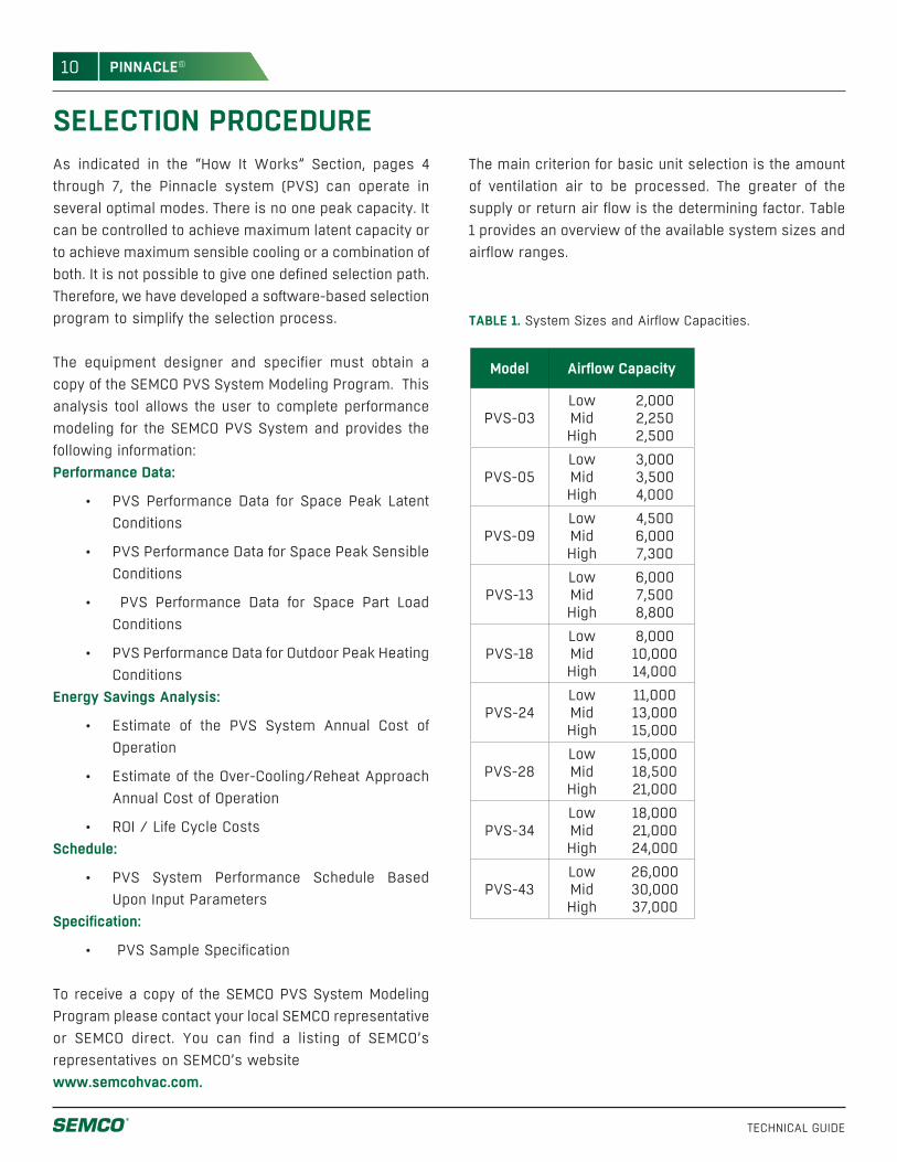
SELECTION PROCEDUREAs indicated in the “How It Works” Section, pages 4 through 7, the Pinnacle system (PVS) can operate in several optimal modes. There is no one peak capacity. It can be controlled to achieve maximum latent capacity or to achieve maximum sensible cooling or a combination of both. It is not possible to give one defined selection path. Therefore, we have developed a software-based selection program to simplify the selection process.
The equipment designer and specifier must obtain a copy of the SEMCO PVS System Modeling Program. This analysis tool allows the user to complete performance modeling for the SEMCO PVS System and provides the following information: Performance Data:
• PVS Performance Data for Space Peak Latent Conditions
• PVS Performance Data for Space Peak Sensible Conditions
• PVS Performance Data for Space Part Load Conditions
• PVS Performance Data for Outdoor Peak Heating Conditions
Energy Savings Analysis:
• Estimate of the PVS System Annual Cost of Operation
• Estimate of the Over-Cooling/Reheat Approach Annual Cost of Operation
• ROI / Life Cycle CostsSchedule:
• PVS System Performance Schedule Based Upon Input Parameters
Specification:
• PVS Sample Specification
To receive a copy of the SEMCO PVS System Modeling Program please contact your local SEMCO representative or SEMCO direct. You can find a listing of SEMCO’s representatives on SEMCO’s website www.semcohvac.com.
TABLE 1. System Sizes and Airflow Capacities.
Model Airflow Capacity
PVS-03LowMidHigh
2,0002,2502,500
PVS-05LowMidHigh
3,0003,5004,000
PVS-09LowMidHigh
4,5006,0007,300
PVS-13LowMidHigh
6,0007,5008,800
PVS-18LowMidHigh
8,00010,00014,000
PVS-24LowMidHigh
11,00013,00015,000
PVS-28LowMidHigh
15,00018,50021,000
PVS-34LowMidHigh
18,00021,00024,000
PVS-43LowMidHigh
26,00030,00037,000
The main criterion for basic unit selection is the amount of ventilation air to be processed. The greater of the supply or return air flow is the determining factor. Table 1 provides an overview of the available system sizes and airflow ranges.

11
TECHNICAL GUIDE
PINNACLE®
UNIT WEIGHTS AND DIMENSIONS
ModelW H A B C D E F G Weight
Mod#1WeightMod#2
WeightMod#3 L L1 L2 L3 L4
(in.) (in.) (in.) (in.) (in.) (in.) (in.) (in.) (in.) (lbs.) (lbs.) (lbs.) (in.) (in.) (in.) (in.) (in.)
PVS-03 86.25 48.25 14.25 24.25 12.25 20 14.25 24 12.25 7,400# 0 0 288.5 0 0 0 0
PVS-05 86.25 60.25 15.25 34.25 14.25 20 20.25 24 14.25 8,700# 0 0 296.5 0 0 0 0
PVS-09 98.25 72.25 15.25 46.25 20.25 20 21.25 34 14.25 11,000# 0 0 304.38 0 0 0 0
PVS-13 98.25 86.25 23.25 46.25 17.25 26 29.25 34 11.25 4,400# 9,750# 0 333.13 99.63 233.5 0 0
PVS-18 122.25 98.25 23.25 58.25 23.25 26 29.25 46 17.25 5,800# 12,250# 0 348.88 107.5 241.38 0 0
PVS-24 122.25 110.25 29.25 58.25 20.25 32 35.25 46 14.25 6,700# 14,150# 0 364.63 115.38 249.25 0 0
PVS-28 146.25 122.25 29.25 70.25 26.25 32 35.25 58 20.25 8,050# 8,800# 9,950# 381.5 119.25 0 133 129.13
PVS-35 146.25 134.25 35.25 70.25 22.75 37 41.25 58 16.75 9,200# 9,950# 11,050# 401.13 129.13 0 137 135
PVS-43 182.25 146.25 29.25 94.25 3.252 44 41.25 70 20.25 11,800# 11,800# 13,650# 417 137 0 139 141
L3 L4L1 L2
D
F
B
D
F
B
FB
EA
C D
S.A. R.A.
D G
BF
E A
G
O.A.
DD
E.A.
C
L
W
H
W
H
W
PLAN VIEW
OUTDOOR SIDE BUILDING SIDE
S.A.
R.A.E.A.
O.A.
Pinnacle Series (PVS)Sizes 3 - 43
12
TECHNICAL GUIDE
PINNACLE®
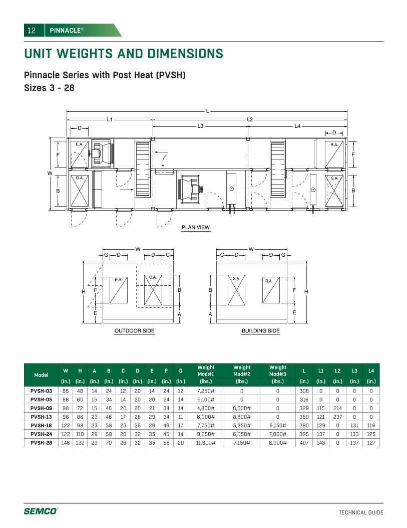
UNIT WEIGHTS AND DIMENSIONS
L3 L4L1 L2
FB
EA
C D
S.A. R.A.
D G
BF
E A
G
O.A.
DD
E.A.
C
B
F
DD
S.A.
R.A.E.A.
O.A.
H
W
H
W
L
W
F
B
PLAN VIEW
OUTDOOR SIDE BUILDING SIDE
ModelW H A B C D E F G Weight
Mod#1WeightMod#2
WeightMod#3 L L1 L2 L3 L4
(in.) (in.) (in.) (in.) (in.) (in.) (in.) (in.) (in.) (lbs.) (lbs.) (lbs.) (in.) (in.) (in.) (in.) (in.)
PVSH-03 86 48 14 24 12 20 14 24 12 7,250# 0 0 308 0 0 0 0
PVSH-05 86 60 15 34 14 20 20 24 14 9,100# 0 0 316 0 0 0 0
PVSH-09 98 72 15 46 20 20 21 34 14 4,800# 6,600# 0 329 115 214 0 0
PVSH-13 98 86 23 46 17 26 29 34 11 6,000# 8,800# 0 359 121 237 0 0
PVSH-18 122 98 23 58 23 26 29 46 17 7,750# 5,350# 6,150# 380 129 0 131 119
PVSH-24 122 110 29 58 20 32 35 46 14 9,050# 6,050# 7,000# 395 137 0 133 125
PVSH-28 146 122 29 70 26 32 35 58 20 11,600# 7,150# 8,000# 407 143 0 137 127
Pinnacle Series with Post Heat (PVSH)Sizes 3 - 28
13
TECHNICAL GUIDE
PINNACLE®
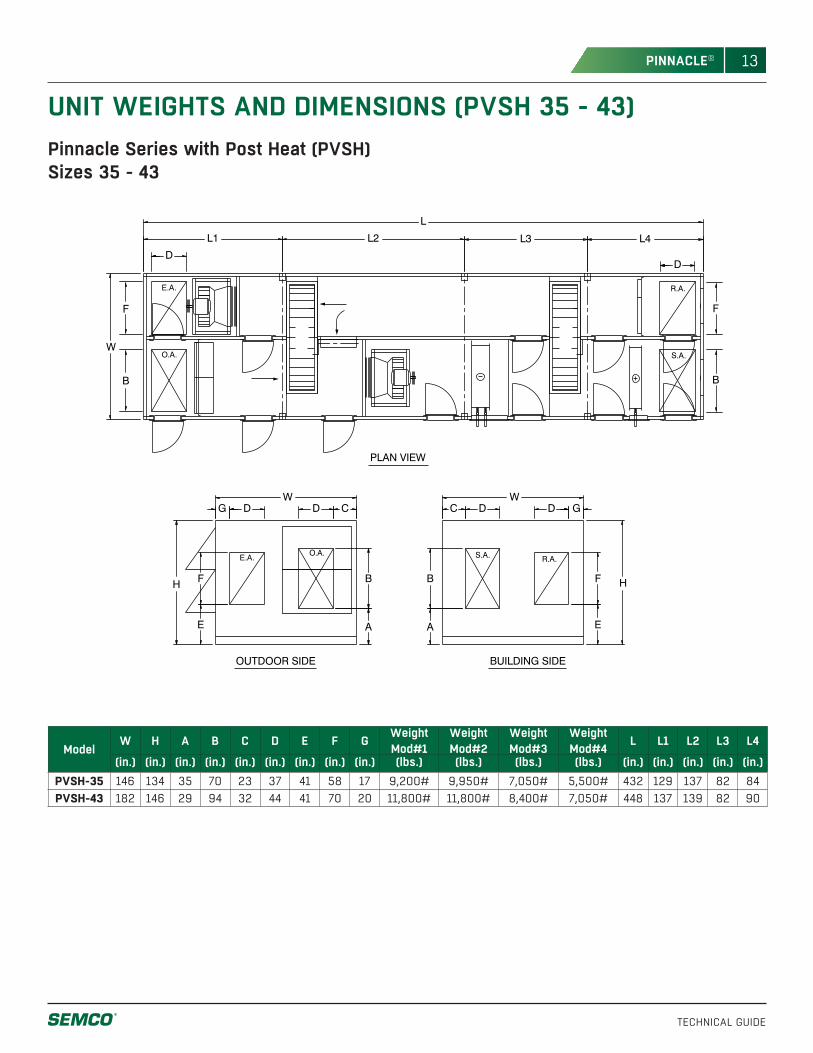
UNIT WEIGHTS AND DIMENSIONS (PVSH 35 - 43)
L3 L4L1 L2
FB
EA
C D
S.A. R.A.
D G
S.A.
R.A.
BF
E A
G
O.A.
DD
E.A.
C
E.A.
O.A.
L
W
H
W
H
W
B
F
DD
F
B
PLAN VIEW
OUTDOOR SIDE BUILDING SIDE
ModelW H A B C D E F G Weight
Mod#1WeightMod#2
WeightMod#3
WeightMod#4 L L1 L2 L3 L4
(in.) (in.) (in.) (in.) (in.) (in.) (in.) (in.) (in.) (lbs.) (lbs.) (lbs.) (lbs.) (in.) (in.) (in.) (in.) (in.)PVSH-35 146 134 35 70 23 37 41 58 17 9,200# 9,950# 7,050# 5,500# 432 129 137 82 84PVSH-43 182 146 29 94 32 44 41 70 20 11,800# 11,800# 8,400# 7,050# 448 137 139 82 90
Pinnacle Series with Post Heat (PVSH)Sizes 35 - 43
14
TECHNICAL GUIDE
PINNACLE®
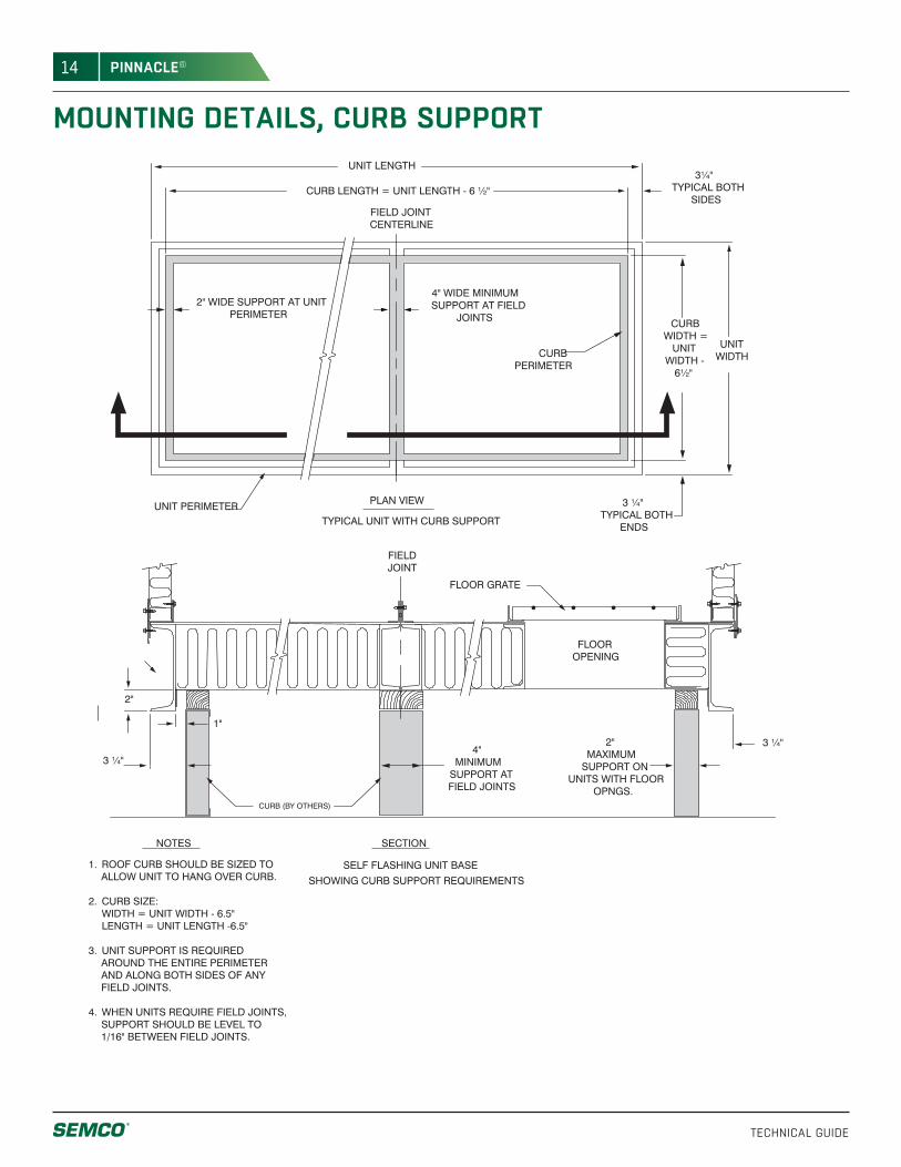
MOUNTING DETAILS, CURB SUPPORTUNIT LENGTH
CURBPERIMETER
UNIT PERIMETER
CURB LENGTH = UNIT LENGTH - 6 ½"
TYPICAL UNIT WITH CURB SUPPORT
PLAN VIEW
CURB WIDTH =
UNIT WIDTH -
6½"
UNIT WIDTH
3 ¼"TYPICAL BOTH
ENDS
4"MINIMUM
SUPPORT AT FIELD JOINTS
2"MAXIMUM
SUPPORT ON UNITS WITH FLOOR
OPNGS.
SELF FLASHING UNIT BASE
SHOWING CURB SUPPORT REQUIREMENTS
1. ROOF CURB SHOULD BE SIZED TO ALLOW UNIT TO HANG OVER CURB.
2. CURB SIZE: WIDTH = UNIT WIDTH - 6.5" LENGTH = UNIT LENGTH -6.5"
3. UNIT SUPPORT IS REQUIRED AROUND THE ENTIRE PERIMETER AND ALONG BOTH SIDES OF ANY FIELD JOINTS.
4. WHEN UNITS REQUIRE FIELD JOINTS, SUPPORT SHOULD BE LEVEL TO 1/16" BETWEEN FIELD JOINTS.
3¼" TYPICAL BOTH
SIDES
2" WIDE SUPPORT AT UNIT PERIMETER
FIELD JOINTCENTERLINE
FIELDJOINT
FLOOR GRATE
FLOOR OPENING
3 ¼"
3 ¼"
CURB (BY OTHERS)
1"
2"
4" WIDE MINIMUMSUPPORT AT FIELD
JOINTS
NOTES SECTION
15
TECHNICAL GUIDE
PINNACLE®
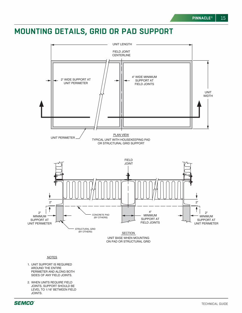
MOUNTING DETAILS, GRID OR PAD SUPPORT
SECTION
UNIT BASE WHEN MOUNTINGON PAD OR STRUCTURAL GRID
PLAN VIEW
TYPICAL UNIT WITH HOUSEKEEPING PADOR STRUCTURAL GRID SUPPORT
UNIT LENGTH
UNIT PERIMETER
UNIT WIDTH
4"MINIMUM
SUPPORT AT FIELD JOINTS
2"MINIMUM
SUPPORT AT UNIT PERIMETER
2"MINIMUM
SUPPORT AT UNIT PERIMETER
NOTES
1. UNIT SUPPORT IS REQUIRED AROUND THE ENTIRE PERIMETER AND ALONG BOTH SIDES OF ANY FIELD JOINTS.
2. WHEN UNITS REQUIRE FIELD JOINTS, SUPPORT SHOULD BE LEVEL TO 1/16" BETWEEN FIELD JOINTS.
2" WIDE SUPPORT AT UNIT PERIMETER
FIELD JOINTCENTERLINE
FIELDJOINT
CONCRETE PAD(BY OTHERS)
2"2"
4" WIDE MINIMUMSUPPORT AT FIELD JOINTS
STRUCTURAL GRID(BY OTHERS)
16
TECHNICAL GUIDE
PINNACLE®
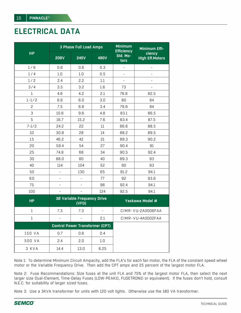
ELECTRICAL DATA
Note 1: To determine Minimum Circuit Ampacity, add the FLA’s for each fan motor, the FLA of the constant speed wheel motor or the Variable Frequency Drive. Then add the CPT amps and 25 percent of the largest motor FLA.
Note 2: Fuse Recommendations: Size fuses at the unit FLA and 75% of the largest motor FLA, then select the next larger size Dual-Element, Time-Delay Fuses (LOW-PEAK©, FUSETRON© or equivalent). If the fuses don’t hold, consult N.E.C. for suitability of larger sized fuses.
Note 3: Use a 3KVA transformer for units with 120 volt lights. Otherwise use the 180 VA transformer.
HP3 Phase Full Load Amps Minimum
EfficiencyStd. Mo-
tors
Minimum Effi-ciency
High Eff.Motors208V 240V 480V
1 /6 0.6 0.6 0.3 - -
1 / 4 1.0 1.0 0.5 - -
1 /2 2.4 2.2 1.1 - -
3/4 3.5 3.2 1.6 73 -
1 4.6 4.2 2.1 76.6 82.5
1-1/2 6.6 6.0 3.0 80 84
2 7.5 6.8 3.4 79.9 84
3 10.6 9.6 4.8 83.1 86.5
5 16.7 15.2 7.6 83.4 87.5
7-1/2 24.2 22 11 86.6 88.5
10 30.8 28 14 88.2 89.5
15 46.2 42 21 89.3 90.2
20 59.4 54 27 90.4 91
25 74.8 68 34 90.5 92.4
30 88.0 80 40 89.3 93
40 114 104 52 90 93
50 - 130 65 91.2 94.1
60 - - 77 92 93.6
75 - - 96 92.4 94.1
100 - - 124 92.5 94.1
HP 3Ø Variable Frequency Drive (VFD) Yaskawa Model #
1 7.3 7.3 - CIMR-VU-2A0006FAA
1 - - 2.1 CIMR-VU-4A0002FAA
Control Power Transformer (CPT)
150 VA 0.7 0.6 0.4
500 VA 2.4 2.0 1.0
3 KVA 14.4 13.0 6.25
17
TECHNICAL GUIDE
PINNACLE®
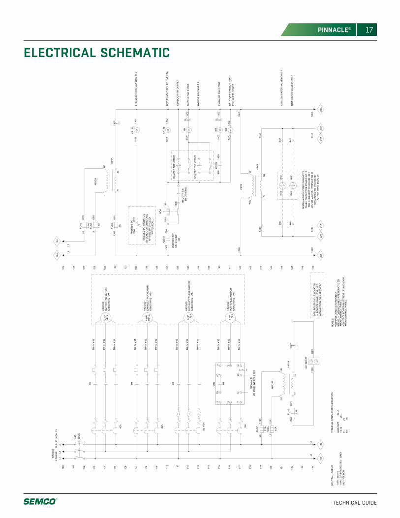
ELECTRICAL SCHEMATIC
124
123
120
122
121
119
118
117
116
115
114
104
112
113
111
110
109
108
107
106
105
103
102
101
100
480/
3/60
FLA
: 30
MC
A: 3
3
138
149
148
145
147
146
144
143
142
141
140
139
137
136
135
134
133
132
130
131
129
128
127
126
125
3M
.63-
1.0A
.5H
P1.
1FLA
10A
.5H
P1.
1FLA
FUS
E
2.5A
1220
1221
FUS
E
1.5A
L112
00
FUS
E
1.5A
L311
90
480/
120
180V
A
GFI
RE
CP
T
1220
1222
125
125
FUS
E
6A
1300
1301
FUS
E
1.5A
L112
80
FUS
E
1.5A
L312
70
480/
24
180V
A
124
124
1350
1351
1360
HO
A
DA
MP
ER
AC
TU
ATO
R
DA
MP
ER
AC
TU
ATO
R
CR
135
1351
1302
1M13
70
2M14
00
OL
1302
OL
1302
3M13
7013
02
CR
228
1370
1400
24/2
4
40V
A
200
200
225
225
1440
1442
1440
1442
1440
1440
1442
1442
CR
132
1320
1302
CR
132
1300
1350
DIS
C
40A
1M
40A
10 H
P14
FLA
2M
30A
7.5H
P11
FLA
249
249
115V
- G
FI P
RO
TEC
TED
- G
RE
Y11
5V -
WH
ITE
24V
- Y
EL
LOW
NE
UTR
AL
LEG
EN
D
6-4
35
8
25
18-1
0
2
0A
WG
SIZ
E
IN-L
B
TER
MIN
AL
TOR
QU
E R
EQ
UIR
EM
EN
TS
MA
IN C
ON
TRO
L P
AN
EL
*CO
PP
ER
CO
ND
UC
TOR
S O
NLY
MA
IN C
ON
TRO
L P
AN
EL
*ITE
MS
IN D
AS
HE
D L
INE
S A
RE
RE
MO
TE T
O
*CO
NTR
OL
PO
WE
R M
US
T N
OT
LEA
VE
MA
IN
NO
TES
:
L3
SA
WS
EK
LMB
SA
WS
EK
LMB
L33
PH
AS
E
SA
WS
EK
LMB
SA
WS
EK
LMBL1
L1
SA
WS
EK
LMB
L2
SA
WS
EK
LMB
SA
WS
EK
LMB
SA
WS
EK
LMB
THH
N #
12
THH
N #
12
THH
N #
12
GR
ND
WIR
E -
#14
EN
THA
LPY
WH
EE
L M
OTO
R48
0/3/
60
PD
H W
HE
EL
MO
TOR
GR
ND
WIR
E -
#14
480/
3/60
THH
N #
12
THH
N #
12
THH
N #
12
FRO
M A
LCI/O
816
8 LI
NE
227
& 2
28
H6
X2
X1
H1
1222
SA
WS
EK
LMB
L1
L
3
H6
X2
X1
H1
1302
RE
MO
TE S
/SB
Y O
THE
RS
CR
MS
MS
MS
W/O
OB
R
W
1442
1440
1302
1300
1300
1302
CH
ILLE
D W
ATE
R V
ALV
E P
OW
ER
HO
T W
ATE
R V
ALV
E P
OW
ER
EN
THA
LPY
WH
EE
L S
TAR
T
EX
HA
US
T FA
N S
TAR
T
BY
PA
SS
AIR
DA
MP
ER
SU
PP
LY F
AN
STA
RT
OU
TDO
OR
AIR
DA
MP
ER
UN
IT E
NA
BLE
RE
LAY,
LIN
E 2
06
PD
H W
HE
EL
STA
RT
GFC
I RE
CE
PTA
CLE
LO
CAT
ED
IN R
EM
OTE
PA
NE
L FO
R U
SE
WIT
H M
OD
EM
OR
LA
PTO
P P
C.
TER
MIN
ALS
PR
OV
IDE
D IN
RE
MO
TEP
AN
EL
TO P
RO
VID
E P
OW
ER
FO
RTH
E C
HIL
LED
WAT
ER
AN
D H
OT
WAT
ER
VA
LVE
S.
WIR
ING
FR
OM
TER
MIN
ALS
TO
VA
LVE
S B
YO
THE
R T
HA
N S
EM
CO
.
FRE
EZE
STA
T13
0013
20
FRE
EZE
STA
T M
OU
NTE
DB
Y S
EM
CO
AT
EN
TER
ING
AIR
SID
E O
F C
HIL
LED
WAT
ER
CO
IL.
CR
FRE
EZE
STA
TR
ELA
Y L
INE
132
1442
1440
FRE
EZE
STA
T R
ELA
Y, L
INE
13
5
SU
PP
LY F
AN
MO
TOR
GR
ND
WIR
E -
#14
480/
3/60
THH
N #
12
THH
N #
12
THH
N #
12
EX
HA
US
T FA
N M
OTO
RG
RN
D W
IRE
- #
14
480/
3/60
THH
N #
12
THH
N #
12
THH
N #
12
VFD
R S T
FR S1
FC SC
U V WE
3M
18
TECHNICAL GUIDE
PINNACLE®
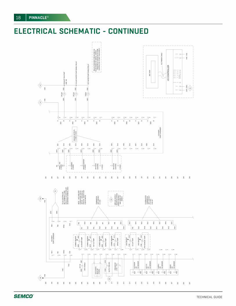
ELECTRICAL SCHEMATIC - CONTINUED
8
224
223
+
RE
D4
220
222
221
+
RE
D-
BLK
219
218
-
BLK +
RE
D
7 8
875 6
6
+
RE
D
217
216
-
BLK
215
214
-
BLK
3
4
2
31
1
2
249
248
2160
2161
AVE
SE
NS
OR
2140
2141
AVE
SE
NS
OR
245
247
246
244
243
242
241
240
239
1442
1440
204
4
4
212
213
211
210
209
6
7
8
6
75
54
CR
135
2060
2061
208
207
206
205
1 3
3
2
21
203
202
201
200
321
149
229
1
2110
2111
CO
MB
O S
EN
SO
R
2090
2091
CO
MB
O S
EN
SO
R
2070
2071
CO
MB
O S
EN
SO
R
2050
2051
CO
MB
O S
EN
SO
R
237
238
236
235
234
233
232
231
230
234D
1
228
227
226
225
149
63
CR
232
2321
1302
84 5 6 7
1235 4
CR
230
2301
1302
CR
228
2281
1302
+
63 2184 5 6 7
+
7814 235
1 2
VIA CC
78
147
147
D1
2100
2101
+ - -+D
2D
2
OA
DA
MPE
R
BYPA
SS
DA
MPE
R
0-10
VDC
WH
EE
L V
FD
AIR
RH
SE
NS
OR
SPA
CE
SU
PPLY
RH
SE
NS
OR
AIR
RH
SE
NS
OR
RH
SE
NS
OR
EN
T C
CA
IR
OU
TDO
OR
AIR
IN16
Gnd
Gnd
IN12
Gnd
Gnd
IN15
IN11
PDH
EXH
AUS
T TE
MP
CC
LAT
TE
MP
Gnd
Gnd
Gnd
IN14
IN10
Gnd
IN9
IN13
24Va
c
Gnd
UN
IT E
NA
BLE
SAWSE
K
LMB
1440
1442
Net
-
Net
+
Gnd
SPA
CE
TE
MP
SU
PPLY
TE
MP
IN4
Gnd
Gnd
IN8
Gnd
Gnd
IN3
IN7
Gnd
EN
T C
C T
EM
P
OU
TDO
OR
TE
MP
IN6
Gnd
IN2
Gnd
Gnd
IN5
IN1
POIN
T E
XPA
ND
ER
I/O 8
168-
R
2020
24Va
c
Net
-
Net
+20
10
SAWSE
K
LMB
ON
MA
RK
ED
TE
RM
INA
L O
NLY
.S
HIE
LD A
T i/O
CO
NTR
OLL
ER
NE
T TE
RM
INA
LS. L
AN
DTO
I/O
CO
NTR
OLL
ER
CR
I/O 8
168-
RPO
INT
EXP
AN
DE
R
Gnd
AO
8
Gnd
AO
7
Gnd
B
DO
7
DO
8
ABA
DO
6
B
HO
T W
ATE
R P
UM
P E
NA
BLE
RE
LAY
CR
CR
1302
AA
O2
Gnd
AO
6
AO
5
Gnd
2310
AO
4
Gnd
AO
3
Gnd
B A
DO
5
AB
DO
4
A
DO
3
BA
DO
2
B
2270
2280
2290
Gnd
AO
1
B
DO
1
A
1300
CH
ILLE
D W
ATE
R P
UM
P E
NA
BLE
RE
LAY
EXH
AUS
T FA
N S
TAR
TLI
NE
140
2020
2010N E T +
1440
1442
I/O C
ON
TRO
LLE
R
TE
N E T -
I L D
Tx1+
S HEN
TT
TE
2-
Rx1-
2+
DLI
ENEN
ENHS
4 V A C2G N D
ALC
RIB
BO
N C
AB
LE
BA
C V
IEW
OC
C/U
NO
CC
RE
LAY
BYO
THE
RS
SU
PPLY
FA
N A
FS
2330
2340
CW
VA
LVE
CO
NTR
OL
DR
Y C
ON
TAC
T0-
10 V
DC
0-20
mA
THE
RM
ISTO
RPL
ATIN
UM
RTD
DR
Y C
ON
TAC
TTH
ER
MIS
TOR
0-5
VDC
SH
IELD
S -
EXC
EPT
FO
RIN
PUTS
. G
RO
UN
D A
LLPL
EN
UM
WIR
E F
OR
ALL
NO
TE:
US
E S
HIE
LDE
D
0-20
mA
INPU
TS.
AIR
FLO
W S
WIT
CH
MO
UN
TED
AC
RO
SS
SU
PPLY
FA
N W
ALL
AN
D W
IRE
D B
YS
EM
CO
.
CO
NTR
OLS
BY
OTH
ER
TH
AN
SE
MC
O.
FRO
M R
ELA
Y C
ON
TAC
TS T
O P
UM
PVA
LVE
EN
AB
LE B
Y S
EM
CO
. W
IRIN
G
RE
LAYS
PR
OVI
DE
D F
OR
HW
AN
D C
W
AN
ALO
G O
UTP
UTS
1-4
AR
E 0
-10V
DC
0-10
VDC
0-10
VDC
0-10
VDC
CO
NTR
OL
HW
VA
LVE
0-10
VDC
2360
2370
FRE
EZE
STA
T21
20
212
1
19
TECHNICAL GUIDE
PINNACLE®
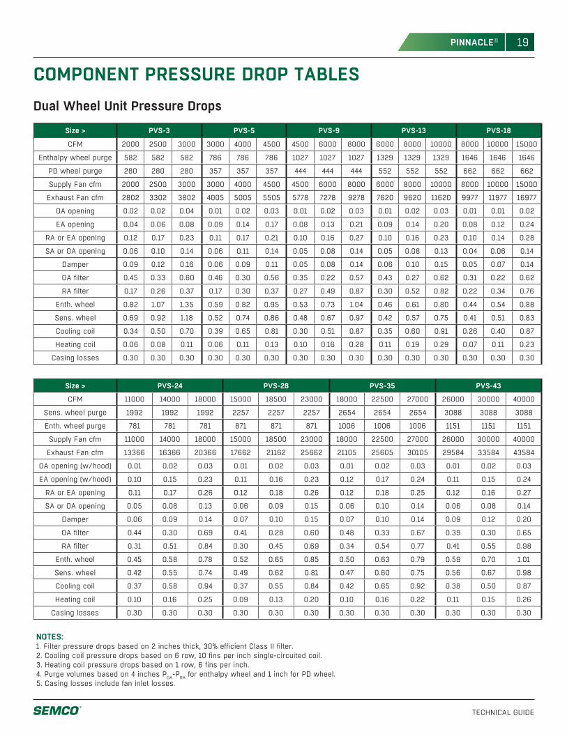
COMPONENT PRESSURE DROP TABLESDual Wheel Unit Pressure Drops
Size > PVS-3 PVS-5 PVS-9 PVS-13 PVS-18
CFM 2000 2500 3000 3000 4000 4500 4500 6000 8000 6000 8000 10000 8000 10000 15000
Enthalpy wheel purge 582 582 582 786 786 786 1027 1027 1027 1329 1329 1329 1646 1646 1646
PD wheel purge 280 280 280 357 357 357 444 444 444 552 552 552 662 662 662
Supply Fan cfm 2000 2500 3000 3000 4000 4500 4500 6000 8000 6000 8000 10000 8000 10000 15000
Exhaust Fan cfm 2802 3302 3802 4005 5005 5505 5778 7278 9278 7620 9620 11620 9977 11977 16977
OA opening 0.02 0.02 0.04 0.01 0.02 0.03 0.01 0.02 0.03 0.01 0.02 0.03 0.01 0.01 0.02
EA opening 0.04 0.06 0.08 0.09 0.14 0.17 0.08 0.13 0.21 0.09 0.14 0.20 0.08 0.12 0.24
RA or EA opening 0.12 0.17 0.23 0.11 0.17 0.21 0.10 0.16 0.27 0.10 0.16 0.23 0.10 0.14 0.28
SA or OA opening 0.06 0.10 0.14 0.06 0.11 0.14 0.05 0.08 0.14 0.05 0.08 0.13 0.04 0.06 0.14
Damper 0.09 0.12 0.16 0.06 0.09 0.11 0.05 0.08 0.14 0.06 0.10 0.15 0.05 0.07 0.14
OA filter 0.45 0.33 0.60 0.46 0.30 0.56 0.35 0.22 0.57 0.43 0.27 0.62 0.31 0.22 0.62
RA filter 0.17 0.26 0.37 0.17 0.30 0.37 0.27 0.49 0.87 0.30 0.52 0.82 0.22 0.34 0.76
Enth. wheel 0.82 1.07 1.35 0.59 0.82 0.95 0.53 0.73 1.04 0.46 0.61 0.80 0.44 0.54 0.88
Sens. wheel 0.69 0.92 1.18 0.52 0.74 0.86 0.48 0.67 0.97 0.42 0.57 0.75 0.41 0.51 0.83
Cooling coil 0.34 0.50 0.70 0.39 0.65 0.81 0.30 0.51 0.87 0.35 0.60 0.91 0.26 0.40 0.87
Heating coil 0.06 0.08 0.11 0.06 0.11 0.13 0.10 0.16 0.28 0.11 0.19 0.29 0.07 0.11 0.23
Casing losses 0.30 0.30 0.30 0.30 0.30 0.30 0.30 0.30 0.30 0.30 0.30 0.30 0.30 0.30 0.30
Size > PVS-24 PVS-28 PVS-35 PVS-43
CFM 11000 14000 18000 15000 18500 23000 18000 22500 27000 26000 30000 40000
Sens. wheel purge 1992 1992 1992 2257 2257 2257 2654 2654 2654 3088 3088 3088
Enth. wheel purge 781 781 781 871 871 871 1006 1006 1006 1151 1151 1151
Supply Fan cfm 11000 14000 18000 15000 18500 23000 18000 22500 27000 26000 30000 40000
Exhaust Fan cfm 13366 16366 20366 17662 21162 25662 21105 25605 30105 29584 33584 43584
OA opening (w/hood) 0.01 0.02 0.03 0.01 0.02 0.03 0.01 0.02 0.03 0.01 0.02 0.03
EA opening (w/hood) 0.10 0.15 0.23 0.11 0.16 0.23 0.12 0.17 0.24 0.11 0.15 0.24
RA or EA opening 0.11 0.17 0.26 0.12 0.18 0.26 0.12 0.18 0.25 0.12 0.16 0.27
SA or OA opening 0.05 0.08 0.13 0.06 0.09 0.15 0.06 0.10 0.14 0.06 0.08 0.14
Damper 0.06 0.09 0.14 0.07 0.10 0.15 0.07 0.10 0.14 0.09 0.12 0.20
OA filter 0.44 0.30 0.69 0.41 0.28 0.60 0.48 0.33 0.67 0.39 0.30 0.65
RA filter 0.31 0.51 0.84 0.30 0.45 0.69 0.34 0.54 0.77 0.41 0.55 0.98
Enth. wheel 0.45 0.58 0.78 0.52 0.65 0.85 0.50 0.63 0.79 0.59 0.70 1.01
Sens. wheel 0.42 0.55 0.74 0.49 0.62 0.81 0.47 0.60 0.75 0.56 0.67 0.98
Cooling coil 0.37 0.58 0.94 0.37 0.55 0.84 0.42 0.65 0.92 0.38 0.50 0.87
Heating coil 0.10 0.16 0.25 0.09 0.13 0.20 0.10 0.16 0.22 0.11 0.15 0.26
Casing losses 0.30 0.30 0.30 0.30 0.30 0.30 0.30 0.30 0.30 0.30 0.30 0.30
NOTES: 1. Filter pressure drops based on 2 inches thick, 30% efficient Class II filter.2. Cooling coil pressure drops based on 6 row, 10 fins per inch single-circuited coil.3. Heating coil pressure drops based on 1 row, 6 fins per inch.4. Purge volumes based on 4 inches POA-PRA for enthalpy wheel and 1 inch for PD wheel.5. Casing losses include fan inlet losses.
20
TECHNICAL GUIDE
PINNACLE®
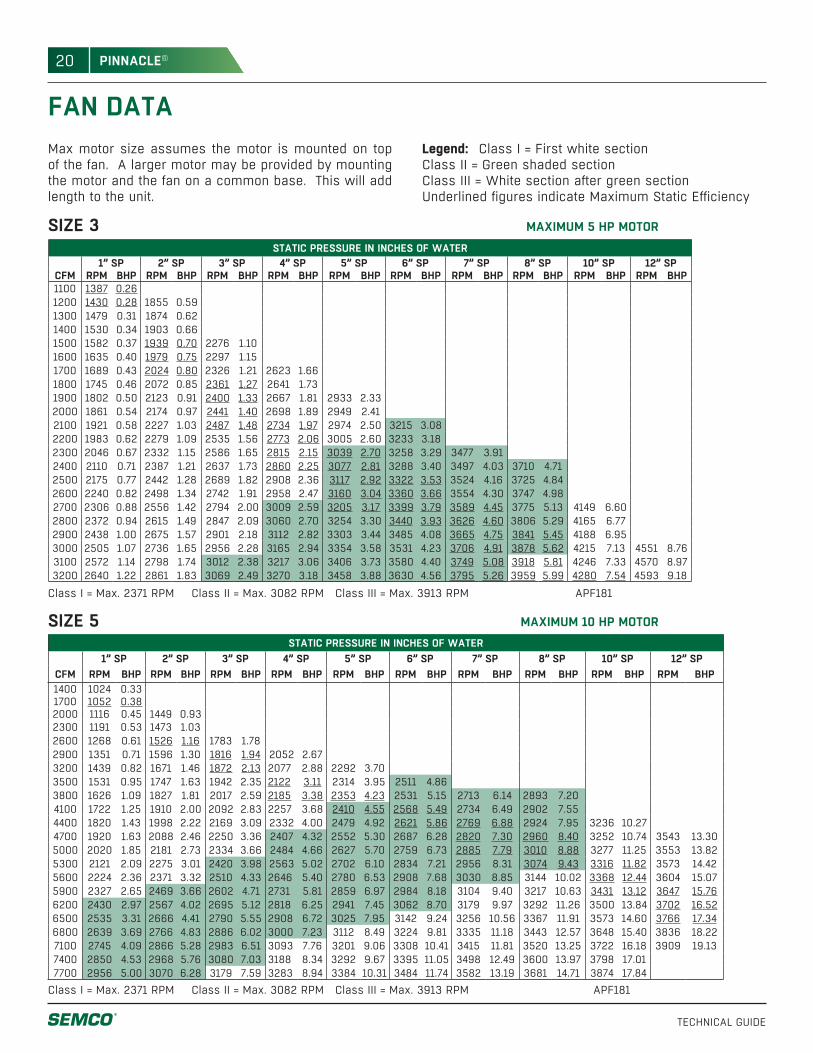
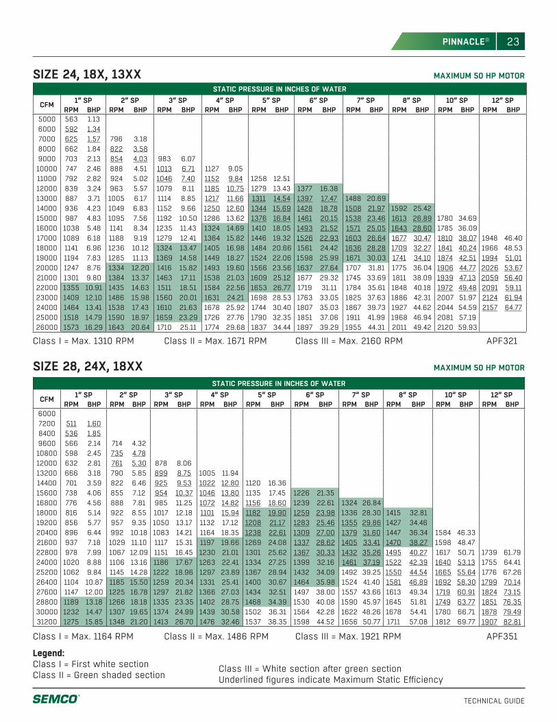
FAN DATAMax motor size assumes the motor is mounted on top of the fan. A larger motor may be provided by mounting the motor and the fan on a common base. This will add length to the unit.
Legend: Class I = First white sectionClass II = Green shaded sectionClass III = White section after green section Underlined figures indicate Maximum Static Efficiency
SIZE 3 MAXIMUM 5 HP MOTORSTATIC PRESSURE IN INCHES OF WATER
1” SP 2” SP 3” SP 4” SP 5” SP 6” SP 7” SP 8” SP 10” SP 12” SPCFM RPM BHP RPM BHP RPM BHP RPM BHP RPM BHP RPM BHP RPM BHP RPM BHP RPM BHP RPM BHP1100 1387 0.261200 1430 0.28 1855 0.591300 1479 0.31 1874 0.621400 1530 0.34 1903 0.661500 1582 0.37 1939 0.70 2276 1.101600 1635 0.40 1979 0.75 2297 1.151700 1689 0.43 2024 0.80 2326 1.21 2623 1.661800 1745 0.46 2072 0.85 2361 1.27 2641 1.731900 1802 0.50 2123 0.91 2400 1.33 2667 1.81 2933 2.332000 1861 0.54 2174 0.97 2441 1.40 2698 1.89 2949 2.412100 1921 0.58 2227 1.03 2487 1.48 2734 1.97 2974 2.50 3215 3.082200 1983 0.62 2279 1.09 2535 1.56 2773 2.06 3005 2.60 3233 3.182300 2046 0.67 2332 1.15 2586 1.65 2815 2.15 3039 2.70 3258 3.29 3477 3.912400 2110 0.71 2387 1.21 2637 1.73 2860 2.25 3077 2.81 3288 3.40 3497 4.03 3710 4.712500 2175 0.77 2442 1.28 2689 1.82 2908 2.36 3117 2.92 3322 3.53 3524 4.16 3725 4.842600 2240 0.82 2498 1.34 2742 1.91 2958 2.47 3160 3.04 3360 3.66 3554 4.30 3747 4.982700 2306 0.88 2556 1.42 2794 2.00 3009 2.59 3205 3.17 3399 3.79 3589 4.45 3775 5.13 4149 6.602800 2372 0.94 2615 1.49 2847 2.09 3060 2.70 3254 3.30 3440 3.93 3626 4.60 3806 5.29 4165 6.772900 2438 1.00 2675 1.57 2901 2.18 3112 2.82 3303 3.44 3485 4.08 3665 4.75 3841 5.45 4188 6.953000 2505 1.07 2736 1.65 2956 2.28 3165 2.94 3354 3.58 3531 4.23 3706 4.91 3878 5.62 4215 7.13 4551 8.763100 2572 1.14 2798 1.74 3012 2.38 3217 3.06 3406 3.73 3580 4.40 3749 5.08 3918 5.81 4246 7.33 4570 8.973200 2640 1.22 2861 1.83 3069 2.49 3270 3.18 3458 3.88 3630 4.56 3795 5.26 3959 5.99 4280 7.54 4593 9.18
Class I = Max. 2371 RPM Class II = Max. 3082 RPM Class III = Max. 3913 RPM APF181
MAXIMUM 10 HP MOTORSIZE 5 STATIC PRESSURE IN INCHES OF WATER
1” SP 2” SP 3” SP 4” SP 5” SP 6” SP 7” SP 8” SP 10” SP 12” SPCFM RPM BHP RPM BHP RPM BHP RPM BHP RPM BHP RPM BHP RPM BHP RPM BHP RPM BHP RPM BHP1400 1024 0.331700 1052 0.382000 1116 0.45 1449 0.932300 1191 0.53 1473 1.032600 1268 0.61 1526 1.16 1783 1.782900 1351 0.71 1596 1.30 1816 1.94 2052 2.673200 1439 0.82 1671 1.46 1872 2.13 2077 2.88 2292 3.703500 1531 0.95 1747 1.63 1942 2.35 2122 3.11 2314 3.95 2511 4.863800 1626 1.09 1827 1.81 2017 2.59 2185 3.38 2353 4.23 2531 5.15 2713 6.14 2893 7.204100 1722 1.25 1910 2.00 2092 2.83 2257 3.68 2410 4.55 2568 5.49 2734 6.49 2902 7.554400 1820 1.43 1998 2.22 2169 3.09 2332 4.00 2479 4.92 2621 5.86 2769 6.88 2924 7.95 3236 10.274700 1920 1.63 2088 2.46 2250 3.36 2407 4.32 2552 5.30 2687 6.28 2820 7.30 2960 8.40 3252 10.74 3543 13.305000 2020 1.85 2181 2.73 2334 3.66 2484 4.66 2627 5.70 2759 6.73 2885 7.79 3010 8.88 3277 11.25 3553 13.825300 2121 2.09 2275 3.01 2420 3.98 2563 5.02 2702 6.10 2834 7.21 2956 8.31 3074 9.43 3316 11.82 3573 14.425600 2224 2.36 2371 3.32 2510 4.33 2646 5.40 2780 6.53 2908 7.68 3030 8.85 3144 10.02 3368 12.44 3604 15.075900 2327 2.65 2469 3.66 2602 4.71 2731 5.81 2859 6.97 2984 8.18 3104 9.40 3217 10.63 3431 13.12 3647 15.766200 2430 2.97 2567 4.02 2695 5.12 2818 6.25 2941 7.45 3062 8.70 3179 9.97 3292 11.26 3500 13.84 3702 16.526500 2535 3.31 2666 4.41 2790 5.55 2908 6.72 3025 7.95 3142 9.24 3256 10.56 3367 11.91 3573 14.60 3766 17.346800 2639 3.69 2766 4.83 2886 6.02 3000 7.23 3112 8.49 3224 9.81 3335 11.18 3443 12.57 3648 15.40 3836 18.227100 2745 4.09 2866 5.28 2983 6.51 3093 7.76 3201 9.06 3308 10.41 3415 11.81 3520 13.25 3722 16.18 3909 19.137400 2850 4.53 2968 5.76 3080 7.03 3188 8.34 3292 9.67 3395 11.05 3498 12.49 3600 13.97 3798 17.017700 2956 5.00 3070 6.28 3179 7.59 3283 8.94 3384 10.31 3484 11.74 3582 13.19 3681 14.71 3874 17.84
Class I = Max. 2371 RPM Class II = Max. 3082 RPM Class III = Max. 3913 RPM APF181
21
TECHNICAL GUIDE
PINNACLE®
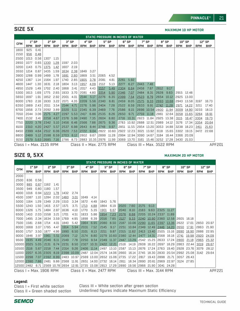
MAXIMUM 20 HP MOTORSIZE 9, 5XX
MAXIMUM 10 HP MOTORSIZE 5X
Legend:Class I = First white section Class II = Green shaded section
Class III = White section after green section Underlined figures indicate Maximum Static Efficiency
STATIC PRESSURE IN INCHES OF WATER
CFM 1” SP 2” SP 3” SP 4” SP 5” SP 6” SP 7” SP 8” SP 10” SP 12” SPRPM BHP RPM BHP RPM BHP RPM BHP RPM BHP RPM BHP RPM BHP RPM BHP RPM BHP RPM BHP
1800 925 0.412150 956 0.482500 1013 0.56 1307 1.152850 1077 0.65 1330 1.28 1597 2.033200 1143 0.75 1375 1.42 1607 2.193550 1214 0.87 1435 1.59 1634 2.38 1849 3.273900 1288 0.99 1499 1.78 1681 2.60 1869 3.51 2065 4.524250 1367 1.14 1564 1.97 1740 2.85 1905 3.78 2081 4.81 2261 5.924600 1447 1.30 1631 2.18 1804 3.13 1957 4.09 2112 5.13 2277 6.27 2443 7.484950 1529 1.49 1702 2.40 1868 3.41 2017 4.43 2157 5.49 2304 6.64 2458 7.87 2612 9.175300 1613 1.69 1775 2.65 1933 3.70 2081 4.80 2214 5.90 2346 7.07 2484 8.31 2628 9.63 2915 12.485650 1697 1.91 1852 2.92 2001 4.01 2144 5.17 2276 6.35 2399 7.54 2523 8.79 2654 10.12 2925 13.006000 1783 2.16 1930 3.22 2071 4.35 2209 5.56 2340 6.81 2459 8.05 2575 9.33 2693 10.68 2943 13.58 3197 16.736350 1869 2.43 2011 3.54 2144 4.71 2276 5.96 2404 7.28 2522 8.59 2633 9.91 2742 11.28 2971 14.22 3211 17.406700 1956 2.73 2092 3.89 2220 5.11 2345 6.39 2469 7.76 2586 9.15 2696 10.54 2800 11.94 3009 14.90 3233 18.137050 2044 3.06 2175 4.27 2297 5.53 2417 6.86 2535 8.26 2650 9.71 2759 11.18 2861 12.64 3058 15.65 3264 18.917400 2132 3.41 2258 4.67 2376 5.98 2490 7.35 2604 8.80 2716 10.31 2823 11.84 2925 13.38 3115 16.47 3304 19.737750 2220 3.78 2342 5.10 2456 6.46 2566 7.88 2675 9.36 2783 10.92 2888 12.51 2989 14.12 3176 17.34 3354 20.648100 2310 4.20 2427 5.57 2537 6.98 2643 8.44 2748 9.97 2851 11.55 2954 13.20 3053 14.88 3238 18.23 3411 21.638450 2399 4.64 2512 6.06 2620 7.53 2722 9.04 2822 10.60 2922 12.23 3021 13.92 3118 15.65 3302 19.15 3472 22.688800 2489 5.12 2598 6.59 2703 8.12 2802 9.67 2899 11.28 2994 12.94 3090 14.67 3184 16.44 3366 20.099150 2579 5.63 2685 7.16 2786 8.73 2883 10.35 2976 11.99 3069 13.70 3161 15.46 3252 17.28 3430 21.03
Class I = Max. 2135 RPM Class II = Max. 2775 RPM Class III = Max. 3522 RPM APF201
STATIC PRESSURE IN INCHES OF WATER
CFM1” SP 2” SP 3” SP 4” SP 5” SP 6” SP 7” SP 8” SP 10” SP 12” SP
RPM BHP RPM BHP RPM BHP RPM BHP RPM BHP RPM BHP RPM BHP RPM BHP RPM BHP RPM BHP20002500 836 0.563000 885 0.67 1162 1.413500 949 0.80 1180 1.574000 1016 0.94 1223 1.78 1432 2.744500 1087 1.10 1284 2.02 1460 3.01 1649 4.145000 1164 1.29 1349 2.29 1510 3.34 1672 4.49 1843 5.765500 1243 1.50 1415 2.57 1571 3.71 1713 4.88 1864 6.19 2020 7.60 2175 9.136000 1326 1.75 1484 2.87 1636 4.10 1770 5.35 1901 6.67 2040 8.10 2183 9.63 2325 11.276500 1410 2.03 1558 3.21 1701 4.51 1833 5.86 1954 7.23 2076 8.68 2205 10.24 2337 11.897000 1495 2.34 1634 3.59 1769 4.95 1898 6.39 2016 7.85 2127 9.33 2240 10.90 2360 12.58 2605 16.187500 1581 2.68 1714 4.01 1840 5.42 1964 6.95 2080 8.50 2187 10.06 2290 11.65 2397 13.36 2622 17.01 2850 20.978000 1668 3.07 1795 4.47 1914 5.94 2031 7.52 2145 9.17 2251 10.84 2349 12.49 2446 14.20 2650 17.91 2863 21.908500 1757 3.50 1877 4.96 1990 6.50 2101 8.13 2211 9.87 2315 11.62 2413 13.40 2505 15.16 2690 18.90 2886 22.959000 1846 3.97 1961 5.51 2069 7.12 2174 8.80 2279 10.60 2380 12.44 2477 14.31 2568 16.18 2741 19.98 2920 24.099500 1935 4.49 2046 6.11 2149 7.78 2250 9.54 2349 11.37 2447 13.29 2542 15.25 2633 17.24 2800 21.18 2965 25.3210000 2025 5.05 2131 6.74 2231 8.50 2327 10.31 2422 12.21 2516 14.19 2608 16.22 2697 18.29 2863 22.44 3019 26.6710500 2116 5.67 2218 7.44 2314 9.26 2406 11.14 2497 13.10 2587 15.13 2676 17.24 2763 19.40 2928 23.76 3079 28.1211000 2207 6.35 2305 8.19 2398 10.09 2487 12.04 2574 14.06 2660 16.14 2745 18.30 2830 20.54 2992 25.08 3142 29.6411500 2298 7.07 2392 8.99 2483 10.97 2569 13.00 2652 15.06 2735 17.22 2817 19.43 2898 21.71 3057 26.4312000 2390 7.86 2481 9.86 2568 11.91 2651 14.00 2732 16.14 2811 18.34 2890 20.61 2969 22.97 3124 27.8512500 2482 8.71 2569 10.78 2654 12.91 2735 15.08 2813 17.29 2890 19.56 2966 21.90 3041 24.28
Class I = Max. 1906 RPM Class II = Max. 2477 RPM Class III = Max. 3144 RPM APF221
22
TECHNICAL GUIDE
PINNACLE®
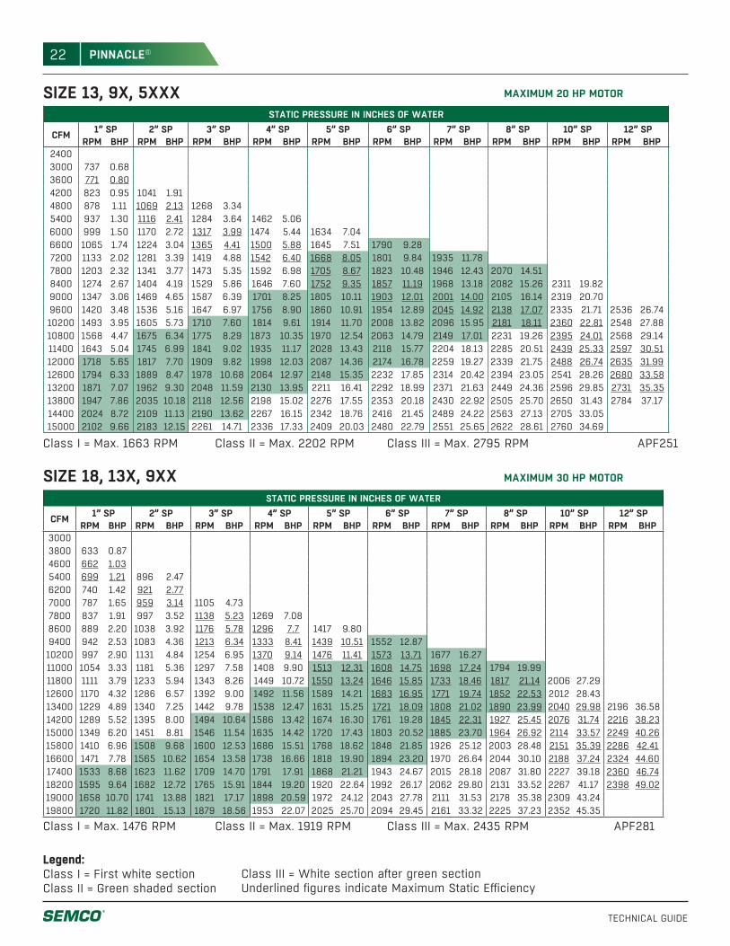
SIZE 13, 9X, 5XXX MAXIMUM 20 HP MOTOR
Legend:Class I = First white section Class II = Green shaded section
Class III = White section after green section Underlined figures indicate Maximum Static Efficiency
Class I = Max. 1663 RPM Class II = Max. 2202 RPM Class III = Max. 2795 RPM APF251
STATIC PRESSURE IN INCHES OF WATER
CFM 1” SP 2” SP 3” SP 4” SP 5” SP 6” SP 7” SP 8” SP 10” SP 12” SPRPM BHP RPM BHP RPM BHP RPM BHP RPM BHP RPM BHP RPM BHP RPM BHP RPM BHP RPM BHP
24003000 737 0.683600 771 0.804200 823 0.95 1041 1.914800 878 1.11 1069 2.13 1268 3.345400 937 1.30 1116 2.41 1284 3.64 1462 5.066000 999 1.50 1170 2.72 1317 3.99 1474 5.44 1634 7.046600 1065 1.74 1224 3.04 1365 4.41 1500 5.88 1645 7.51 1790 9.287200 1133 2.02 1281 3.39 1419 4.88 1542 6.40 1668 8.05 1801 9.84 1935 11.787800 1203 2.32 1341 3.77 1473 5.35 1592 6.98 1705 8.67 1823 10.48 1946 12.43 2070 14.518400 1274 2.67 1404 4.19 1529 5.86 1646 7.60 1752 9.35 1857 11.19 1968 13.18 2082 15.26 2311 19.829000 1347 3.06 1469 4.65 1587 6.39 1701 8.25 1805 10.11 1903 12.01 2001 14.00 2105 16.14 2319 20.709600 1420 3.48 1536 5.16 1647 6.97 1756 8.90 1860 10.91 1954 12.89 2045 14.92 2138 17.07 2335 21.71 2536 26.7410200 1493 3.95 1605 5.73 1710 7.60 1814 9.61 1914 11.70 2008 13.82 2096 15.95 2181 18.11 2360 22.81 2548 27.8810800 1568 4.47 1675 6.34 1775 8.29 1873 10.35 1970 12.54 2063 14.79 2149 17.01 2231 19.26 2395 24.01 2568 29.1411400 1643 5.04 1745 6.99 1841 9.02 1935 11.17 2028 13.43 2118 15.77 2204 18.13 2285 20.51 2439 25.33 2597 30.5112000 1718 5.65 1817 7.70 1909 9.82 1998 12.03 2087 14.36 2174 16.78 2259 19.27 2339 21.75 2488 26.74 2635 31.9912600 1794 6.33 1889 8.47 1978 10.68 2064 12.97 2148 15.35 2232 17.85 2314 20.42 2394 23.05 2541 28.26 2680 33.5813200 1871 7.07 1962 9.30 2048 11.59 2130 13.95 2211 16.41 2292 18.99 2371 21.63 2449 24.36 2596 29.85 2731 35.3513800 1947 7.86 2035 10.18 2118 12.56 2198 15.02 2276 17.55 2353 20.18 2430 22.92 2505 25.70 2650 31.43 2784 37.1714400 2024 8.72 2109 11.13 2190 13.62 2267 16.15 2342 18.76 2416 21.45 2489 24.22 2563 27.13 2705 33.0515000 2102 9.66 2183 12.15 2261 14.71 2336 17.33 2409 20.03 2480 22.79 2551 25.65 2622 28.61 2760 34.69
MAXIMUM 30 HP MOTORSIZE 18, 13X, 9XX STATIC PRESSURE IN INCHES OF WATER
CFM 1” SP 2” SP 3” SP 4” SP 5” SP 6” SP 7” SP 8” SP 10” SP 12” SPRPM BHP RPM BHP RPM BHP RPM BHP RPM BHP RPM BHP RPM BHP RPM BHP RPM BHP RPM BHP
30003800 633 0.874600 662 1.035400 699 1.21 896 2.476200 740 1.42 921 2.777000 787 1.65 959 3.14 1105 4.737800 837 1.91 997 3.52 1138 5.23 1269 7.088600 889 2.20 1038 3.92 1176 5.78 1296 7.7 1417 9.809400 942 2.53 1083 4.36 1213 6.34 1333 8.41 1439 10.51 1552 12.8710200 997 2.90 1131 4.84 1254 6.95 1370 9.14 1476 11.41 1573 13.71 1677 16.2711000 1054 3.33 1181 5.36 1297 7.58 1408 9.90 1513 12.31 1608 14.75 1698 17.24 1794 19.9911800 1111 3.79 1233 5.94 1343 8.26 1449 10.72 1550 13.24 1646 15.85 1733 18.46 1817 21.14 2006 27.2912600 1170 4.32 1286 6.57 1392 9.00 1492 11.56 1589 14.21 1683 16.95 1771 19.74 1852 22.53 2012 28.4313400 1229 4.89 1340 7.25 1442 9.78 1538 12.47 1631 15.25 1721 18.09 1808 21.02 1890 23.99 2040 29.98 2196 36.5814200 1289 5.52 1395 8.00 1494 10.64 1586 13.42 1674 16.30 1761 19.28 1845 22.31 1927 25.45 2076 31.74 2216 38.2315000 1349 6.20 1451 8.81 1546 11.54 1635 14.42 1720 17.43 1803 20.52 1885 23.70 1964 26.92 2114 33.57 2249 40.2615800 1410 6.96 1508 9.68 1600 12.53 1686 15.51 1768 18.62 1848 21.85 1926 25.12 2003 28.48 2151 35.39 2286 42.4116600 1471 7.78 1565 10.62 1654 13.58 1738 16.66 1818 19.90 1894 23.20 1970 26.64 2044 30.10 2188 37.24 2324 44.6017400 1533 8.68 1623 11.62 1709 14.70 1791 17.91 1868 21.21 1943 24.67 2015 28.18 2087 31.80 2227 39.18 2360 46.7418200 1595 9.64 1682 12.72 1765 15.91 1844 19.20 1920 22.64 1992 26.17 2062 29.80 2131 33.52 2267 41.17 2398 49.0219000 1658 10.70 1741 13.88 1821 17.17 1898 20.59 1972 24.12 2043 27.78 2111 31.53 2178 35.38 2309 43.2419800 1720 11.82 1801 15.13 1879 18.56 1953 22.07 2025 25.70 2094 29.45 2161 33.32 2225 37.23 2352 45.35
Class I = Max. 1476 RPM Class II = Max. 1919 RPM Class III = Max. 2435 RPM APF281
23
TECHNICAL GUIDE
PINNACLE®
MAXIMUM 50 HP MOTORSIZE 28, 24X, 18XX
MAXIMUM 50 HP MOTORSIZE 24, 18X, 13XX
Legend:Class I = First white section Class II = Green shaded section
Class III = White section after green section Underlined figures indicate Maximum Static Efficiency
STATIC PRESSURE IN INCHES OF WATER
CFM 1” SP 2” SP 3” SP 4” SP 5” SP 6” SP 7” SP 8” SP 10” SP 12” SPRPM BHP RPM BHP RPM BHP RPM BHP RPM BHP RPM BHP RPM BHP RPM BHP RPM BHP RPM BHP
5000 563 1.136000 592 1.347000 625 1.57 796 3.188000 662 1.84 822 3.589000 703 2.13 854 4.03 983 6.0710000 747 2.46 888 4.51 1013 6.71 1127 9.0511000 792 2.82 924 5.02 1046 7.40 1152 9.84 1258 12.5112000 839 3.24 963 5.57 1079 8.11 1185 10.75 1279 13.43 1377 16.3813000 887 3.71 1005 6.17 1114 8.85 1217 11.66 1311 14.54 1397 17.47 1488 20.6914000 936 4.23 1049 6.83 1152 9.66 1250 12.60 1344 15.69 1428 18.78 1508 21.97 1592 25.4215000 987 4.83 1095 7.56 1192 10.50 1286 13.62 1376 16.84 1461 20.15 1538 23.46 1613 26.89 1780 34.6916000 1038 5.48 1141 8.34 1235 11.43 1324 14.69 1410 18.05 1493 21.52 1571 25.05 1643 28.60 1785 36.0917000 1089 6.18 1188 9.19 1279 12.41 1364 15.82 1446 19.32 1526 22.93 1603 26.64 1677 30.47 1810 38.07 1948 46.4018000 1141 6.96 1236 10.12 1324 13.47 1405 16.98 1484 20.66 1561 24.42 1636 28.28 1709 32.27 1841 40.24 1966 48.5319000 1194 7.83 1285 11.13 1369 14.58 1449 18.27 1524 22.06 1598 25.99 1671 30.03 1741 34.10 1874 42.51 1994 51.0120000 1247 8.76 1334 12.20 1416 15.82 1493 19.60 1566 23.56 1637 27.64 1707 31.81 1775 36.04 1906 44.77 2026 53.6721000 1301 9.80 1384 13.37 1463 17.11 1538 21.03 1609 25.12 1677 29.32 1745 33.69 1811 38.09 1939 47.13 2059 56.4022000 1355 10.91 1435 14.63 1511 18.51 1584 22.56 1653 26.77 1719 31.11 1784 35.61 1848 40.18 1972 49.48 2091 59.1123000 1409 12.10 1486 15.98 1560 20.01 1631 24.21 1698 28.53 1763 33.05 1825 37.63 1886 42.31 2007 51.97 2124 61.9424000 1464 13.41 1538 17.43 1610 21.63 1678 25.92 1744 30.40 1807 35.03 1867 39.73 1927 44.62 2044 54.59 2157 64.7725000 1518 14.79 1590 18.97 1659 23.29 1726 27.76 1790 32.35 1851 37.06 1911 41.99 1968 46.94 2081 57.1926000 1573 16.29 1643 20.64 1710 25.11 1774 29.68 1837 34.44 1897 39.29 1955 44.31 2011 49.42 2120 59.93
Class I = Max. 1310 RPM Class II = Max. 1671 RPM Class III = Max. 2160 RPM APF321
STATIC PRESSURE IN INCHES OF WATER
CFM 1” SP 2” SP 3” SP 4” SP 5” SP 6” SP 7” SP 8” SP 10” SP 12” SPRPM BHP RPM BHP RPM BHP RPM BHP RPM BHP RPM BHP RPM BHP RPM BHP RPM BHP RPM BHP
60007200 511 1.608400 536 1.859600 566 2.14 714 4.3210800 598 2.45 735 4.7812000 632 2.81 761 5.30 878 8.0613200 666 3.18 790 5.85 899 8.75 1005 11.9414400 701 3.59 822 6.46 925 9.53 1022 12.80 1120 16.3615600 738 4.06 855 7.12 954 10.37 1046 13.80 1135 17.45 1226 21.3516800 776 4.56 888 7.81 985 11.25 1072 14.82 1156 18.60 1239 22.61 1324 26.8418000 816 5.14 922 8.55 1017 12.18 1101 15.94 1182 19.90 1259 23.98 1336 28.30 1415 32.8119200 856 5.77 957 9.35 1050 13.17 1132 17.12 1208 21.17 1283 25.46 1355 29.86 1427 34.4620400 896 6.44 992 10.18 1083 14.21 1164 18.35 1238 22.61 1309 27.00 1379 31.60 1447 36.34 1584 46.3321600 937 7.18 1029 11.10 1117 15.31 1197 19.66 1269 24.08 1337 28.62 1405 33.41 1470 38.27 1598 48.4722800 978 7.99 1067 12.09 1151 16.45 1230 21.01 1301 25.62 1367 30.33 1432 35.26 1495 40.27 1617 50.71 1739 61.7924000 1020 8.88 1106 13.16 1186 17.67 1263 22.41 1334 27.25 1399 32.16 1461 37.19 1522 42.39 1640 53.13 1755 64.4125200 1062 9.84 1145 14.28 1222 18.96 1297 23.89 1367 28.94 1432 34.09 1492 39.25 1550 44.54 1665 55.64 1776 67.2626400 1104 10.87 1185 15.50 1259 20.34 1331 25.41 1400 30.67 1464 35.98 1524 41.40 1581 46.89 1692 58.30 1799 70.1427600 1147 12.00 1225 16.78 1297 21.82 1366 27.03 1434 32.51 1497 38.00 1557 43.66 1613 49.34 1719 60.91 1824 73.1528800 1189 13.18 1266 18.18 1335 23.35 1402 28.75 1468 34.39 1530 40.08 1590 45.97 1645 51.81 1749 63.77 1851 76.3530000 1232 14.47 1307 19.65 1374 24.99 1439 30.58 1502 36.31 1564 42.28 1622 48.26 1678 54.41 1780 66.71 1878 79.4931200 1275 15.85 1348 21.20 1413 26.70 1476 32.46 1537 38.35 1598 44.52 1656 50.77 1711 57.08 1812 69.77 1907 82.81
Class I = Max. 1164 RPM Class II = Max. 1486 RPM Class III = Max. 1921 RPM APF351
24
TECHNICAL GUIDE
PINNACLE®
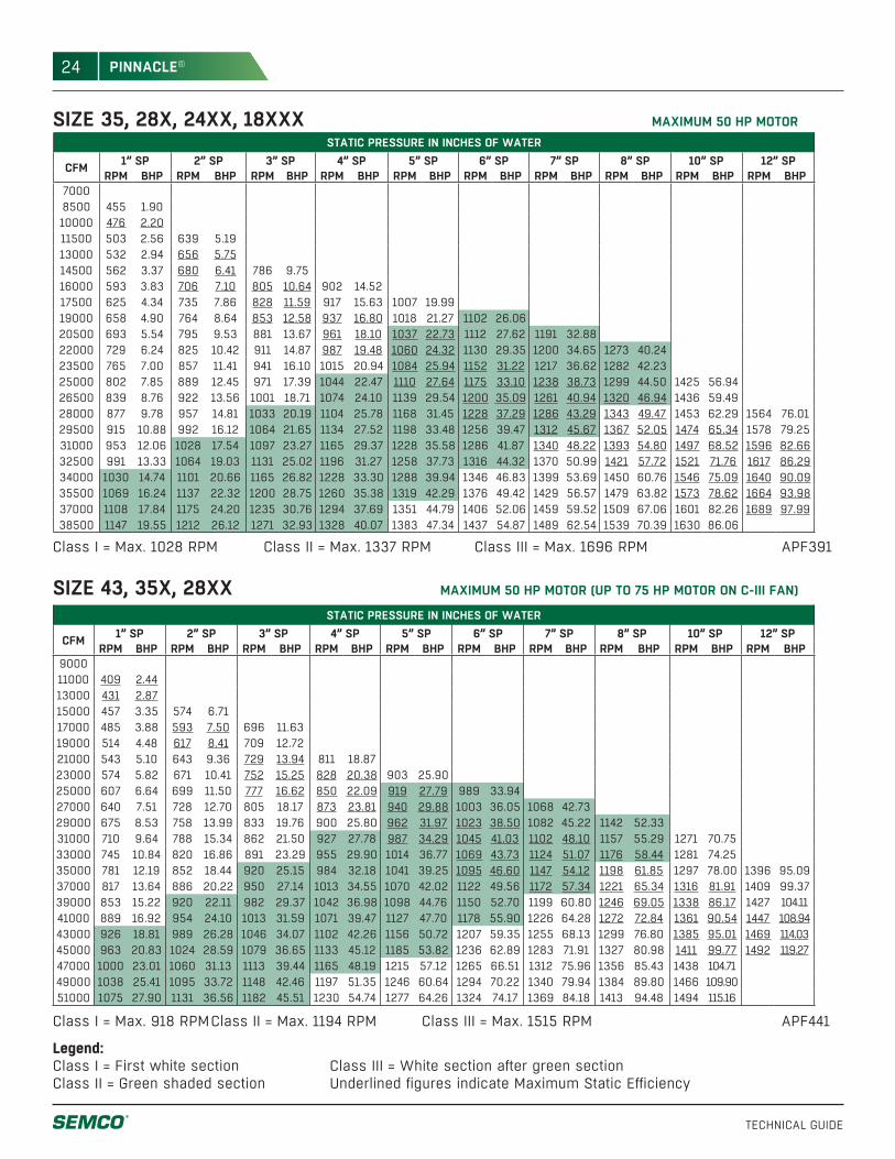
SIZE 35, 28X, 24XX, 18XXX MAXIMUM 50 HP MOTOR
Legend:Class I = First white section Class II = Green shaded section
Class III = White section after green section Underlined figures indicate Maximum Static Efficiency
Class I = Max. 1028 RPM Class II = Max. 1337 RPM Class III = Max. 1696 RPM APF391
STATIC PRESSURE IN INCHES OF WATER
CFM 1” SP 2” SP 3” SP 4” SP 5” SP 6” SP 7” SP 8” SP 10” SP 12” SPRPM BHP RPM BHP RPM BHP RPM BHP RPM BHP RPM BHP RPM BHP RPM BHP RPM BHP RPM BHP
70008500 455 1.9010000 476 2.2011500 503 2.56 639 5.1913000 532 2.94 656 5.7514500 562 3.37 680 6.41 786 9.7516000 593 3.83 706 7.10 805 10.64 902 14.5217500 625 4.34 735 7.86 828 11.59 917 15.63 1007 19.9919000 658 4.90 764 8.64 853 12.58 937 16.80 1018 21.27 1102 26.0620500 693 5.54 795 9.53 881 13.67 961 18.10 1037 22.73 1112 27.62 1191 32.8822000 729 6.24 825 10.42 911 14.87 987 19.48 1060 24.32 1130 29.35 1200 34.65 1273 40.2423500 765 7.00 857 11.41 941 16.10 1015 20.94 1084 25.94 1152 31.22 1217 36.62 1282 42.2325000 802 7.85 889 12.45 971 17.39 1044 22.47 1110 27.64 1175 33.10 1238 38.73 1299 44.50 1425 56.9426500 839 8.76 922 13.56 1001 18.71 1074 24.10 1139 29.54 1200 35.09 1261 40.94 1320 46.94 1436 59.4928000 877 9.78 957 14.81 1033 20.19 1104 25.78 1168 31.45 1228 37.29 1286 43.29 1343 49.47 1453 62.29 1564 76.0129500 915 10.88 992 16.12 1064 21.65 1134 27.52 1198 33.48 1256 39.47 1312 45.67 1367 52.05 1474 65.34 1578 79.2531000 953 12.06 1028 17.54 1097 23.27 1165 29.37 1228 35.58 1286 41.87 1340 48.22 1393 54.80 1497 68.52 1596 82.6632500 991 13.33 1064 19.03 1131 25.02 1196 31.27 1258 37.73 1316 44.32 1370 50.99 1421 57.72 1521 71.76 1617 86.2934000 1030 14.74 1101 20.66 1165 26.82 1228 33.30 1288 39.94 1346 46.83 1399 53.69 1450 60.76 1546 75.09 1640 90.0935500 1069 16.24 1137 22.32 1200 28.75 1260 35.38 1319 42.29 1376 49.42 1429 56.57 1479 63.82 1573 78.62 1664 93.9837000 1108 17.84 1175 24.20 1235 30.76 1294 37.69 1351 44.79 1406 52.06 1459 59.52 1509 67.06 1601 82.26 1689 97.9938500 1147 19.55 1212 26.12 1271 32.93 1328 40.07 1383 47.34 1437 54.87 1489 62.54 1539 70.39 1630 86.06
MAXIMUM 50 HP MOTOR (UP TO 75 HP MOTOR ON C-III FAN)SIZE 43, 35X, 28XXSTATIC PRESSURE IN INCHES OF WATER
CFM 1” SP 2” SP 3” SP 4” SP 5” SP 6” SP 7” SP 8” SP 10” SP 12” SPRPM BHP RPM BHP RPM BHP RPM BHP RPM BHP RPM BHP RPM BHP RPM BHP RPM BHP RPM BHP
900011000 409 2.4413000 431 2.8715000 457 3.35 574 6.7117000 485 3.88 593 7.50 696 11.6319000 514 4.48 617 8.41 709 12.7221000 543 5.10 643 9.36 729 13.94 811 18.8723000 574 5.82 671 10.41 752 15.25 828 20.38 903 25.9025000 607 6.64 699 11.50 777 16.62 850 22.09 919 27.79 989 33.9427000 640 7.51 728 12.70 805 18.17 873 23.81 940 29.88 1003 36.05 1068 42.7329000 675 8.53 758 13.99 833 19.76 900 25.80 962 31.97 1023 38.50 1082 45.22 1142 52.3331000 710 9.64 788 15.34 862 21.50 927 27.78 987 34.29 1045 41.03 1102 48.10 1157 55.29 1271 70.7533000 745 10.84 820 16.86 891 23.29 955 29.90 1014 36.77 1069 43.73 1124 51.07 1176 58.44 1281 74.2535000 781 12.19 852 18.44 920 25.15 984 32.18 1041 39.25 1095 46.60 1147 54.12 1198 61.85 1297 78.00 1396 95.0937000 817 13.64 886 20.22 950 27.14 1013 34.55 1070 42.02 1122 49.56 1172 57.34 1221 65.34 1316 81.91 1409 99.3739000 853 15.22 920 22.11 982 29.37 1042 36.98 1098 44.76 1150 52.70 1199 60.80 1246 69.05 1338 86.17 1427 104.1141000 889 16.92 954 24.10 1013 31.59 1071 39.47 1127 47.70 1178 55.90 1226 64.28 1272 72.84 1361 90.54 1447 108.9443000 926 18.81 989 26.28 1046 34.07 1102 42.26 1156 50.72 1207 59.35 1255 68.13 1299 76.80 1385 95.01 1469 114.0345000 963 20.83 1024 28.59 1079 36.65 1133 45.12 1185 53.82 1236 62.89 1283 71.91 1327 80.98 1411 99.77 1492 119.2747000 1000 23.01 1060 31.13 1113 39.44 1165 48.19 1215 57.12 1265 66.51 1312 75.96 1356 85.43 1438 104.7149000 1038 25.41 1095 33.72 1148 42.46 1197 51.35 1246 60.64 1294 70.22 1340 79.94 1384 89.80 1466 109.9051000 1075 27.90 1131 36.56 1182 45.51 1230 54.74 1277 64.26 1324 74.17 1369 84.18 1413 94.48 1494 115.16
Class I = Max. 918 RPM Class II = Max. 1194 RPM Class III = Max. 1515 RPM APF441
25
TECHNICAL GUIDE
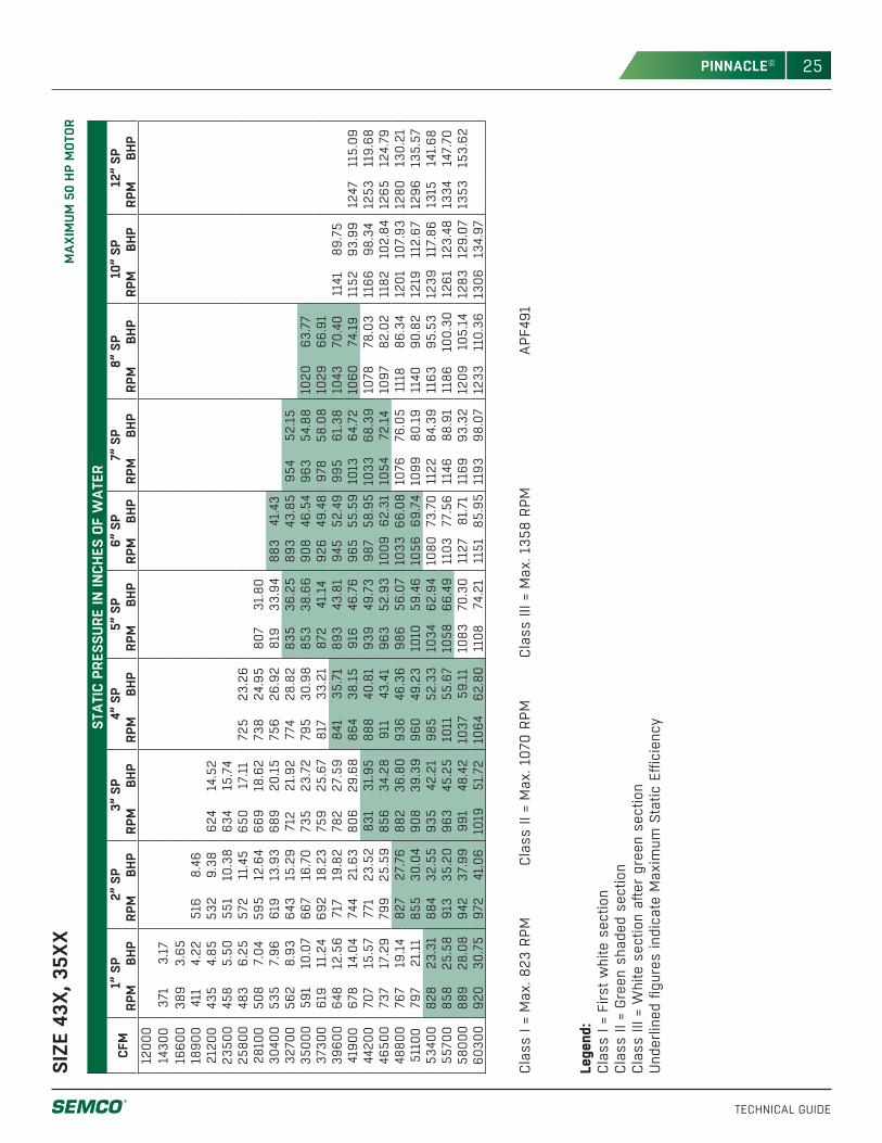
PINNACLE®M
AXIM
UM 5
0 HP
MOT
ORSI
ZE 4
3X, 3
5XX
STAT
IC P
RESS
URE
IN IN
CHES
OF
WAT
ERCF
M1”
SP
2” S
P3”
SP
4” S
P5”
SP
6” S
P7”
SP
8” S
P10
” SP
12”
SPRP
MBH
PRP
MBH
PRP
MBH
PRP
MBH
PRP
MBH
PRP
MBH
PRP
MBH
PRP
MBH
PRP
MBH
PRP
MBH
P12
000
1430
037
13.
1716
600
389
3.65
1890
041
14.
2251
68.
4621
200
435
4.85
532
9.38
624
14.5
223
500
458
5.50
551
10.3
863
415
.74
2580
048
36.
2557
211
.45
650
17.1
172
523
.26
2810
050
87.
0459
512
.64
669
18.6
273
824
.95
807
31.8
030
400
535
7.96
619
13.9
368
920
.15
756
26.9
281
933
.94
883
41.4
332
700
562
8.93
643
15.2
971
221
.92
774
28.8
283
536
.25
893
43.8
595
452
.15
3500
059
110
.07
667
16.7
073
523
.72
795
30.9
885
338
.66
908
46.5
496
354
.88
1020
63.7
737
300
619
11.2
469
218
.23
759
25.6
781
733
.21
872
41.1
492
649
.48
978
58.0
810
2966
.91
3960
064
812
.56
717
19.8
278
227
.59
841
35.7
189
343
.81
945
52.4
999
561
.38
1043
70.4
011
4189
.75
4190
067
814
.04
744
21.6
380
629
.68
864
38.1
591
646
.76
965
55.5
910
1364
.72
1060
74.1
911
5293
.99
1247
115.
0944
200
707
15.5
777
123
.52
831
31.9
588
840
.81
939
49.7
398
758
.95
1033
68.3
910
7878
.03
1166
98.3
412
5311
9.68
4650
073
717
.29
799
25.5
985
634
.28
911
43.4
196
352
.93
1009
62.3
110
5472
.14
1097
82.0
211
8210
2.84
1265
124.
7948
800
767
19.1
482
727
.76
882
36.8
093
646
.36
986
56.0
710
3366
.08
1076
76.0
511
1886
.34
1201
107.
9312
8013
0.21
5110
079
721
.11
855
30.0
490
839
.39
960
49.2
310
1059
.46
1056
69.7
410
9980
.19
1140
90.8
212
1911
2.67
1296
135.
5753
400
828
23.3
188
432
.55
935
42.2
198
552
.33
1034
62.9
410
8073
.70
1122
84.3
911
6395
.53
1239
117.
8613
1514
1.68
5570
085
825
.58
913
35.2
096
345
.25
1011
55.6
710
5866
.49
1103
77.5
611
4688
.91
1186
100.
3012
6112
3.48
1334
147.
7058
000
889
28.0
894
237
.99
991
48.4
210
3759
.11
1083
70.3
011
2781
.71
1169
93.3
212
0910
5.14
1283
129.
0713
5315
3.62
6030
092
030
.75
972
41.0
610
1951
.72
1064
62.8
011
0874
.21
1151
85.9
511
9398
.07
1233
110.
3613
0613
4.97
Clas
s I =
Max
. 823
RPM
Cl
ass
II =
Max
. 107
0 RP
M
Clas
s III
= M
ax. 1
358
RPM
A
PF49
1
Lege
nd:
Clas
s I =
Firs
t whi
te s
ectio
n Cl
ass
II =
Gree
n sh
aded
sec
tion
Clas
s III
= W
hite
sec
tion
afte
r gr
een
sect
ion
Und
erlin
ed fi
gure
s in
dica
te M
axim
um S
tatic
Effi
cien
cy
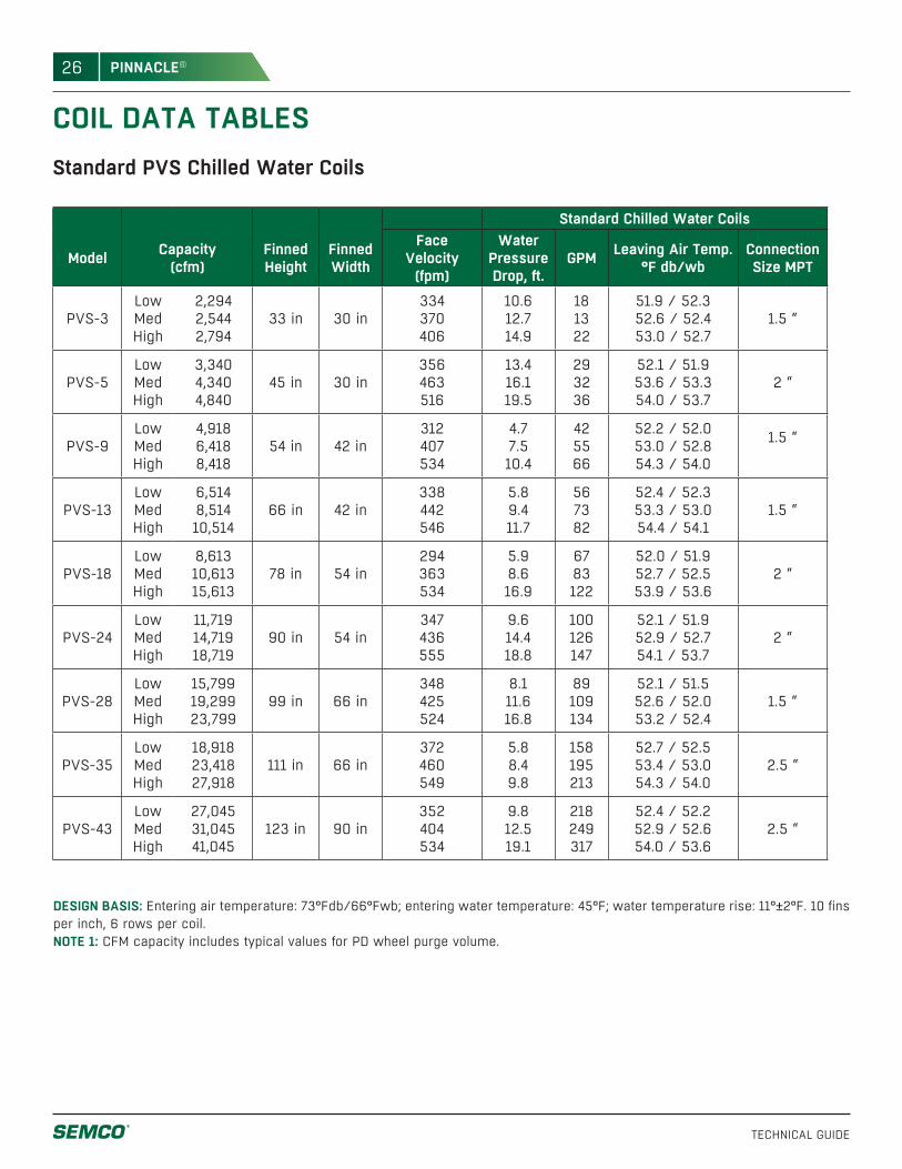
26
TECHNICAL GUIDE
PINNACLE®
COIL DATA TABLESStandard PVS Chilled Water Coils
DESIGN BASIS: Entering air temperature: 73°Fdb/66°Fwb; entering water temperature: 45°F; water temperature rise: 11°±2°F. 10 fins per inch, 6 rows per coil.NOTE 1: CFM capacity includes typical values for PD wheel purge volume.
Standard Chilled Water Coils
Model Capacity(cfm)
FinnedHeight
FinnedWidth
Face Velocity
(fpm)
Water PressureDrop, ft.
GPM Leaving Air Temp.°F db/wb
ConnectionSize MPT
PVS-3LowMedHigh
2,2942,5442,794
33 in 30 in334370406
10.612.714.9
181322
51.9 / 52.352.6 / 52.453.0 / 52.7
1.5 “
PVS-5LowMedHigh
3,3404,3404,840
45 in 30 in356463516
13.416.119.5
293236
52.1 / 51.953.6 / 53.354.0 / 53.7
2 “
PVS-9LowMedHigh
4,9186,4188,418
54 in 42 in312407534
4.77.510.4
425566
52.2 / 52.053.0 / 52.854.3 / 54.0
1.5 “
PVS-13LowMedHigh
6,5148,51410,514
66 in 42 in338442546
5.89.411.7
567382
52.4 / 52.353.3 / 53.054.4 / 54.1
1.5 “
PVS-18LowMedHigh
8,61310,61315,613
78 in 54 in294363534
5.98.616.9
6783122
52.0 / 51.952.7 / 52.553.9 / 53.6
2 “
PVS-24LowMedHigh
11,71914,71918,719
90 in 54 in347436555
9.614.418.8
100126147
52.1 / 51.952.9 / 52.754.1 / 53.7
2 “
PVS-28LowMedHigh
15,79919,29923,799
99 in 66 in348425524
8.111.616.8
89109134
52.1 / 51.552.6 / 52.053.2 / 52.4
1.5 “
PVS-35LowMedHigh
18,91823,41827,918
111 in 66 in372460549
5.88.49.8
158195213
52.7 / 52.553.4 / 53.054.3 / 54.0
2.5 “
PVS-43LowMedHigh
27,04531,04541,045
123 in 90 in352404534
9.812.519.1
218249317
52.4 / 52.252.9 / 52.654.0 / 53.6
2.5 “
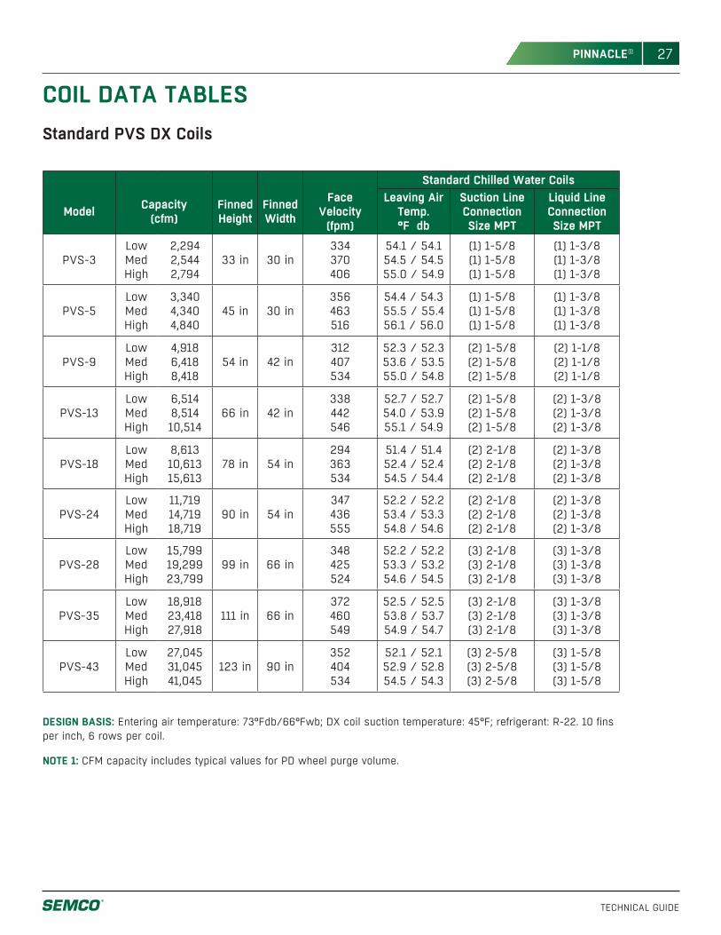
27
TECHNICAL GUIDE
PINNACLE®
Standard PVS DX Coils
COIL DATA TABLES
DESIGN BASIS: Entering air temperature: 73°Fdb/66°Fwb; DX coil suction temperature: 45°F; refrigerant: R-22. 10 fins per inch, 6 rows per coil.
NOTE 1: CFM capacity includes typical values for PD wheel purge volume.
Face Velocity
(fpm)
Standard Chilled Water Coils
Model Capacity(cfm)
FinnedHeight
FinnedWidth
Leaving Air Temp.°F db
Suction Line Connection Size MPT
Liquid Line Connection Size MPT
PVS-3LowMedHigh
2,2942,5442,794
33 in 30 in334370406
54.1 / 54.154.5 / 54.555.0 / 54.9
(1) 1-5/8 (1) 1-5/8(1) 1-5/8
(1) 1-3/8(1) 1-3/8(1) 1-3/8
PVS-5LowMedHigh
3,3404,3404,840
45 in 30 in356463516
54.4 / 54.355.5 / 55.456.1 / 56.0
(1) 1-5/8 (1) 1-5/8(1) 1-5/8
(1) 1-3/8(1) 1-3/8(1) 1-3/8
PVS-9LowMedHigh
4,9186,4188,418
54 in 42 in312407534
52.3 / 52.353.6 / 53.555.0 / 54.8
(2) 1-5/8(2) 1-5/8(2) 1-5/8
(2) 1-1/8(2) 1-1/8(2) 1-1/8
PVS-13LowMedHigh
6,5148,51410,514
66 in 42 in338442546
52.7 / 52.754.0 / 53.955.1 / 54.9
(2) 1-5/8(2) 1-5/8(2) 1-5/8
(2) 1-3/8(2) 1-3/8(2) 1-3/8
PVS-18LowMedHigh
8,61310,61315,613
78 in 54 in294363534
51.4 / 51.452.4 / 52.454.5 / 54.4
(2) 2-1/8(2) 2-1/8(2) 2-1/8
(2) 1-3/8(2) 1-3/8(2) 1-3/8
PVS-24LowMedHigh
11,71914,71918,719
90 in 54 in347436555
52.2 / 52.253.4 / 53.354.8 / 54.6
(2) 2-1/8(2) 2-1/8(2) 2-1/8
(2) 1-3/8(2) 1-3/8(2) 1-3/8
PVS-28LowMedHigh
15,79919,29923,799
99 in 66 in348425524
52.2 / 52.253.3 / 53.254.6 / 54.5
(3) 2-1/8(3) 2-1/8(3) 2-1/8
(3) 1-3/8(3) 1-3/8(3) 1-3/8
PVS-35LowMedHigh
18,91823,41827,918
111 in 66 in372460549
52.5 / 52.553.8 / 53.754.9 / 54.7
(3) 2-1/8(3) 2-1/8(3) 2-1/8
(3) 1-3/8(3) 1-3/8(3) 1-3/8
PVS-43LowMedHigh
27,04531,04541,045
123 in 90 in352404534
52.1 / 52.152.9 / 52.854.5 / 54.3
(3) 2-5/8(3) 2-5/8(3) 2-5/8
(3) 1-5/8(3) 1-5/8(3) 1-5/8
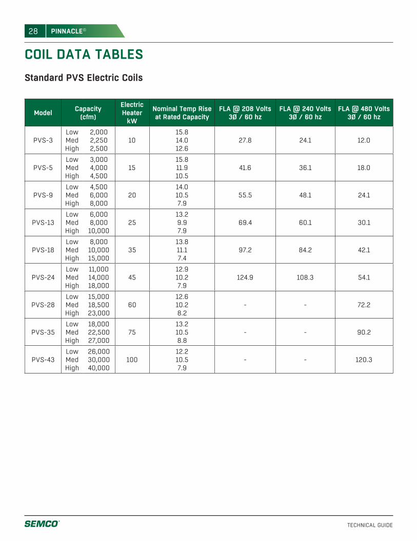
28
TECHNICAL GUIDE
PINNACLE®
COIL DATA TABLESStandard PVS Electric Coils
Model Capacity(cfm)
Electric Heater
kW
Nominal Temp Rise at Rated Capacity
FLA @ 208 Volts3Ø / 60 hz
FLA @ 240 Volts3Ø / 60 hz
FLA @ 480 Volts3Ø / 60 hz
PVS-3LowMedHigh
2,0002,2502,500
1015.814.012.6
27.8 24.1 12.0
PVS-5LowMedHigh
3,0004,0004,500
1515.811.910.5
41.6 36.1 18.0
PVS-9LowMedHigh
4,5006,0008,000
2014.010.57.9
55.5 48.1 24.1
PVS-13LowMedHigh
6,0008,00010,000
2513.29.97.9
69.4 60.1 30.1
PVS-18LowMedHigh
8,00010,00015,000
3513.811.17.4
97.2 84.2 42.1
PVS-24LowMedHigh
11,00014,00018,000
4512.910.27.9
124.9 108.3 54.1
PVS-28LowMedHigh
15,00018,50023,000
6012.610.28.2
- - 72.2
PVS-35LowMedHigh
18,00022,50027,000
7513.210.58.8
- - 90.2
PVS-43LowMedHigh
26,00030,00040,000
10012.210.57.9
- - 120.3
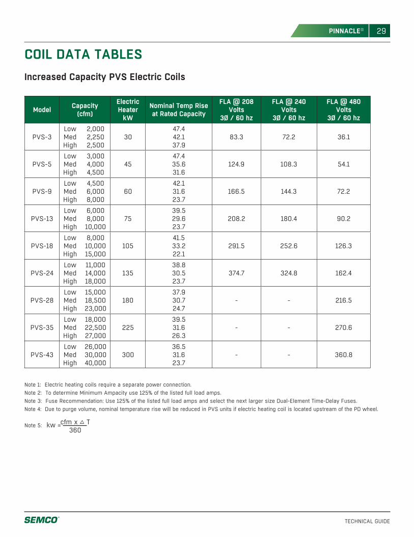
29
TECHNICAL GUIDE
PINNACLE®
Increased Capacity PVS Electric Coils
Model Capacity(cfm)
Electric Heater
kW
Nominal Temp Rise at Rated Capacity
FLA @ 208 Volts
3Ø / 60 hz
FLA @ 240 Volts
3Ø / 60 hz
FLA @ 480 Volts
3Ø / 60 hz
PVS-3LowMedHigh
2,0002,2502,500
3047.442.137.9
83.3 72.2 36.1
PVS-5LowMedHigh
3,0004,0004,500
4547.435.631.6
124.9 108.3 54.1
PVS-9LowMedHigh
4,5006,0008,000
6042.131.623.7
166.5 144.3 72.2
PVS-13LowMedHigh
6,0008,00010,000
7539.529.623.7
208.2 180.4 90.2
PVS-18LowMedHigh
8,00010,00015,000
10541.533.222.1
291.5 252.6 126.3
PVS-24LowMedHigh
11,00014,00018,000
13538.830.523.7
374.7 324.8 162.4
PVS-28LowMedHigh
15,00018,50023,000
18037.930.724.7
- - 216.5
PVS-35LowMedHigh
18,00022,50027,000
22539.531.626.3
- - 270.6
PVS-43LowMedHigh
26,00030,00040,000
30036.531.623.7
- - 360.8
Note 1: Electric heating coils require a separate power connection. Note 2: To determine Minimum Ampacity use 125% of the listed full load amps.Note 3: Fuse Recommendation: Use 125% of the listed full load amps and select the next larger size Dual-Element Time-Delay Fuses.Note 4: Due to purge volume, nominal temperature rise will be reduced in PVS units if electric heating coil is located upstream of the PD wheel.
Note 5: kw = cfm x T360
COIL DATA TABLES
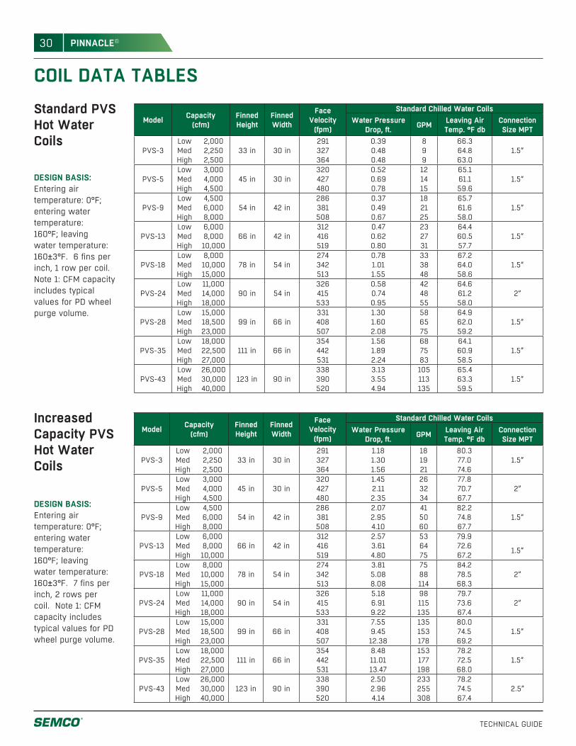
30
TECHNICAL GUIDE
PINNACLE®
COIL DATA TABLESStandard PVS Hot Water Coils
DESIGN BASIS: Entering air temperature: 0°F; entering water temperature: 160°F; leaving water temperature: 160±3°F. 6 fins per inch, 1 row per coil. Note 1: CFM capacity includes typical values for PD wheel purge volume.
DESIGN BASIS: Entering air temperature: 0°F; entering water temperature: 160°F; leaving water temperature: 160±3°F. 7 fins per inch, 2 rows per coil. Note 1: CFM capacity includes typical values for PD wheel purge volume.
Increased Capacity PVS Hot Water Coils
Model Capacity(cfm)
FinnedHeight
FinnedWidth
Face Velocity
(fpm)
Standard Chilled Water CoilsWater Pressure
Drop, ft. GPM Leaving Air Temp. °F db
ConnectionSize MPT
PVS-3LowMedHigh
2,0002,2502,500
33 in 30 in291327364
0.390.480.48
899
66.364.863.0
1.5”
PVS-5LowMedHigh
3,0004,0004,500
45 in 30 in320427480
0.520.690.78
121415
65.161.159.6
1.5”
PVS-9LowMedHigh
4,5006,0008,000
54 in 42 in286381508
0.370.490.67
182125
65.761.658.0
1.5”
PVS-13LowMedHigh
6,0008,00010,000
66 in 42 in312416519
0.470.620.80
232731
64.460.557.7
1.5”
PVS-18LowMedHigh
8,00010,00015,000
78 in 54 in274342513
0.781.011.55
333848
67.264.058.6
1.5”
PVS-24LowMedHigh
11,00014,00018,000
90 in 54 in326415533
0.580.740.95
424855
64.661.258.0
2”
PVS-28LowMedHigh
15,00018,50023,000
99 in 66 in331408507
1.301.602.08
586575
64.962.059.2
1.5”
PVS-35LowMedHigh
18,00022,50027,000
111 in 66 in354442531
1.561.892.24
687583
64.160.958.5
1.5”
PVS-43LowMedHigh
26,00030,00040,000
123 in 90 in338390520
3.133.554.94
105113135
65.463.359.5
1.5”
Model Capacity(cfm)
FinnedHeight
FinnedWidth
Face Velocity
(fpm)
Standard Chilled Water CoilsWater Pressure
Drop, ft. GPM Leaving Air Temp. °F db
ConnectionSize MPT
PVS-3LowMedHigh
2,0002,2502,500
33 in 30 in291327364
1.181.301.56
181921
80.377.074.6
1.5”
PVS-5LowMedHigh
3,0004,0004,500
45 in 30 in320427480
1.452.112.35
263234
77.870.767.7
2”
PVS-9LowMedHigh
4,5006,0008,000
54 in 42 in286381508
2.072.954.10
415060
82.274.867.7
1.5”
PVS-13LowMedHigh
6,0008,00010,000
66 in 42 in312416519
2.573.614.80
536475
79.972.667.2 1.5”
PVS-18LowMedHigh
8,00010,00015,000
78 in 54 in274342513
3.815.088.08
7588114
84.278.568.3
2”
PVS-24LowMedHigh
11,00014,00018,000
90 in 54 in326415533
5.186.919.22
98115135
79.773.667.4
2”
PVS-28LowMedHigh
15,00018,50023,000
99 in 66 in331408507
7.559.4512.38
135153178
80.074.569.2
1.5”
PVS-35LowMedHigh
18,00022,50027,000
111 in 66 in354442531
8.4811.0113.47
153177198
78.272.568.0
1.5”
PVS-43LowMedHigh
26,00030,00040,000
123 in 90 in338390520
2.502.964.14
233255308
78.274.567.4
2.5”
31
TECHNICAL GUIDE
PINNACLE®
SAMPLE SPECIFICATIONSA. Casing - Standard panels shall consist of 2” thick dual wall 18 gauge (20 gauge for unit sizes 3, 5, and 9) galvanized solid exterior skins and 22 gauge galvanized steel solid interior skins enclosing 2 inch thick 3 pcf mineral wool insulation with a U-factor of 0.10 BTU/(hr-sq.ft.-deg.) The housing shall be supported by a painted structural steel base. The base includes a solid welded floor with 6” thick (4” thick for unit sizes 3, 5, and 9) mineral wool insulation. The bottom face of the insulation shall be protected with a 22 gauge galvanized steel cover. The base is to be self-flashing when set on a properly sized curb. Floor openings have perimeter lips turned up into unit and are covered by a protective grate. Lifting lugs shall be welded to the structural base.
B. Outdoor Construction - Units shall have a factory-installed, 24 gauge galvanized steel standing seam sheet metal sloped roof. Roof field joints will consist of tapered expanded polystyrene filler panels and standing seam metal roof that must be installed and crimped by the contractor. Outdoor air intake and exhaust air discharge openings shall have galvanized steel sheet metal hoods with openings covered with bird screen. Hoods may ship loose for field installation depending on shipping width restrictions.
Outdoor Intake Filters - Research Products Industrial EZ-Kleen, Aluminum mesh, 1” thick, washable filters shall be mounted in the outdoor air intake hoods. These shall be a low resistance-roughing filter.
C. Access - Access shall be provided through large hinged, tightly sealed doors or easily removable access panels. Access doors shall be constructed of the same materials as the unit casing and use SEMCO’s standard hardware. Each door shall be provided with two cam type handles and two heavy duty hinges to achieve maximum sealing. Handles are to be internal and external for opening from the inside or outside of the unit. All doors shall be air pressure closing. Removable panels shall be provided for heating and cooling coils.
D. Fans - Fan performance is based on tests conducted in accordance with AMCA Standard test code for air
moving devices and shall bear the AMCA Certified Rating Seal for Air and Sound. Fans have a sharply rising pressure characteristic extending through the operating range and continuing to rise beyond the efficiency peak to ensure quiet and stable operation. Fans shall be of the centrifugal plenum type, designed without a scroll type housing. Fans shall incorporate a non-overloading type backward inclined airfoil blade wheel, heavy gauge reinforced steel inlet plate with removable spun inlet cone, structural steel frame, and shaft and bearings in the AMCA Arrangement 3 configuration to form a heavy duty integral unit. Fan wheels have a spun non-tapered style blade-retaining ring on the inlet side to allow higher efficiencies over the performance range of the fan. Sizes 281 and larger shall have nine die-formed hollow airfoil blades continuously welded around all edges. Smaller sizes shall have nine airfoil-shaped aluminum extruded blades. Fan wheels are statically and dynamically balanced to a level of G6.3 (per ANSI 2-19) or better.
Shafts - The fan shaft is polished steel, accurately turned, ground and ring gauged for accuracy. Shafts shall have first critical speeds at least 1.43 times the maximum speeds of the fan.
Bearings - The fan wheel bearings are heavy duty, grease lubricated, anti-friction ball or roller, self-aligning, pillow block type and selected for minimum average bearing life (AFBMA L-50) in excess of 200,000 hours at the maximum class RPM.
Fan vibration isolation - Fans assemblies shall have adjustable motor bases, motors and V-belt drives mounted with the assembly mounted on spring isolators with flexible connections between fan and fan wall. Drive belts shall be designed for a minimum 1.4 service factor. Drives shall be fixed pitch.
Motors - Fan motors shall be standard NEMA frame, EPACT compliant, with 1.15 service factor and open drip-proof enclosures.
E. Enthalpy Recovery Wheel - The rotor media shall be made of aluminum, which is coated to prohibit
32
TECHNICAL GUIDE
PINNACLE®
corrosion. All media surfaces shall be coated with a non-migrating solid adsorbent layer prior to being formed into the honeycomb media structure to insure that all surfaces are coated and that adequate latent capacity is provided. The media has a flame spread of less than 25 and a smoke developed of less than 50 when rated in accordance with ASTM E84.
The faces of the total energy recovery wheel shall be sealed with a two-part polymer acid resistant coating to limit surface oxidation. The media face coating shall also include a proprietary Teflon-based anti-stick additive shown, by independent testing, to effectively limit the collection of dust or smoke particulate and to aid in the surface cleaning process should cleaning be required.
The entire recovery wheel media face shall be treated with Avron46, and shall exhibit effective antimicrobial action, supported by independent test data. Any antimicrobial agent used must, by law, carry an EPA registration for use in duct systems. All desiccant surfaces within the transfer media shall also exhibit bacteria-static properties as supported by independent testing.
The desiccant is inorganic and specifically developed for the selective adsorption of water vapor. The desiccant utilizes a 3A molecular sieve certified by the manufacturer to have an internal pore diameter distribution, which limits adsorption to materials not larger than the critical diameter of a water molecule (2.8 angstroms.)
Equal sensible and latent recovery efficiencies are documented through a certification program conducted in accordance with ASHRAE 84-78P and the results presented in accordance with ARI 1060 standards. The certification has been conducted by a qualified independent organization.
Independent wheel testing from a credible test laboratory documents that the desiccant material utilized does not transfer pollutants typically encountered in the indoor air environment. The cross-contamination and performance certification reports shall be provided upon written request for engineering review.
F. Passive Dehumidification Wheel - The Passive Dehumidification wheel shall be specifically designed to dehumidify the outdoor air stream leaving the cooling coil, without the use of additional regeneration energy of any type. The dehumidification wheel media backbone shall be an aluminum film substrate. The substrate shall be coated, prior to being formed into the honeycomb media structure, with a dense layer of solid, non-migrating adsorbent desiccant materials specifically designed to provide optimum dehumidification performance. The desiccant coating and wheel media are suitable for use in a saturated, high humidity environment and cleanable with low temperature steam or hot water without adversely affecting performance. The media has a flame spread rating of less than 25 and a smoke developed of less than 50 when rated in accordance with ASTM E84.
G. Rotor Maintenance - The media is cleanable with low-pressure steam (less than 5 psi,) hot water or light detergent, without degrading the latent recovery. Dry particles up to 800 microns shall freely pass through the media.
Purge Sector - The unit is provided with a factory set, field adjustable purge sector designed to limit cross contamination to less than .04 percent of that of the exhaust air stream concentration when operated under appropriate conditions.
Rotor Seals - The rotor is supplied with labyrinth seals only, which at no time are required to make contact with any rotating surface of the exchanger rotor face. These multi-pass seals shall utilize four labyrinth stages for optimum performance.
Rotor Support System - The rotor media is provided in segmented fashion to allow for field erection or replacement of one section at a time without requiring side access. The media is rigidly held by a structural spoke system made of extruded aluminum.
Rotor Housing - The rotor housing is a structural framework, which limits the deflection of the rotor due to air pressure to less than 1/32”. The rotor is supported by two pillow block bearings which can be maintained
33
TECHNICAL GUIDE
PINNACLE®
or replaced without the removal of the rotor from its casing or the media from its spoke system.
Drive System - The rotor is driven by a black B-section v-belt and an integral gearmotor for reliable operation. A/C motors are utilized for both constant and variable speed applications.
H. Integral Condensing Unit Section - General - Integral condensing units shall be factory wired, piped, pressure tested, evacuated, charged with R-22, and tested. The energy recovery unit and condensing unit share electrical and control panels.
Compressor - Compressors shall be heavy-duty commercial, high efficiency scrolls with oil level sight glass, low vibration, and discharge and suction Rotalock service valves.
Capacity Control - Single circuit condensing units shall use variable frequency drives for capacity control. Dual circuit condensing units shall be available with either one constant speed and one variable speed circuit for continuously variable capacity, or two circuits split 1/3:2/3 for three capacity steps.
Condenser Coils - Primary surface shall be round 0.375” OD by .012” rifled copper tube with 0.0045” raised lance aluminum fins spaced at no greater than 14 fins per inch. The coils shall be pressure tested to 500 psig with a UL listed ultimate strength of 2400 psig.
Safeties and Piping Specialties - Integral condensing unit shall include the following safeties and piping specialties: Balanced port thermal expansion valve with equalizer, liquid line filter drier, sight glass, auto reset low pressure cutout, manual reset high pressure cutout, solenoid valve, air flow proof, on delay, off delay and minimum run time timers, and low ambient lockout.
Condenser Fan - Condenser fans shall be aluminum blade TCPE type with TEFC motors, bell mouth inlets, and zinc plated steel outlet guard.
I. Outdoor Air Filters - Outdoor air filters shall be 2” disposable.
J. Return Air Filters - Return air filters shall be 2” disposable.
K. 2” Pre-Filters - Filters shall be Farr type 30/30. Air filters shall be 2” thick, pleated, disposable type. Each filter shall consist of a non-woven cotton and synthetic fabric media, media support grid and enclosing frame. Filter media shall be a cotton and synthetic blend with at least 15 pleats per linear foot. A welded wire grid, spot-welded on one-inch centers and treated for corrosion resistance is bonded to the downstream side of the media to maintain the radial pleat and prevent media oscillation. The filter media shall have a Minimum Efficiency Reporting Value of MERV 7 when evaluated under guidelines of ASHRAE Standard 52.2-1999 and an average dust spot efficiency of 25-30% when evaluated under ASHRAE Standard 52.1-1992. The filter is listed by Underwriters’ Laboratories as Class 2. A bank of 16-gauge galvanized steel universal holding frames with filter sealing flange, centering dimples, sealing gasket and lances for air filter fasteners shall be arranged for upstream access. Provisions shall be made on the downstream side of the frames to prevent filter blowout from moisture or overloading.
L. High Efficiency 95% Outdoor Air Filters - Mounted in the same filter bank with the Pre-filters shall be 12” deep high performance filters, which shall be high lofted supported media disposable type. The media blanket shall be formed into uniform tapered radial pleats and bonded to a welded wire media support grid, which is spot-welded on one-inch centers, and treated for corrosion resistance. Media support contour stabilizers shall be mechanically fastened to diagonal support members of the same construction to create a rigid and durable filter enclosure. There shall be a minimum of four contour stabilizers on the air entering side and six on the air exiting side. The media shall have a Minimum Efficiency Reporting Value of MERV 14 when evaluated under guidelines of ASHRAE Standard 52.2-1999 and an average dust spot efficiency of 90-95% when evaluated under ASHRAE Standard 52.1-1992. The filter is listed by Underwriters’ Laboratories as Class 2.
34
TECHNICAL GUIDE
PINNACLE®
M. Chilled Water Coil - Primary surface is round seamless 5/8” O.D. by .020” thick copper tube on 1.5” centers, staggered in the direction of airflow. All joints shall be brazed.
Secondary surface shall consist of .0060” rippled aluminum plate fins for higher capacity and structural strength. Fins shall have full drawn collars to provide a continuous surface cover over the entire tube for maximum heat transfer. Bare copper tube shall not be visible between fins and the fins shall have no openings punched in them to accumulate lint and dirt. Tubes shall be mechanically expanded into the fins to provide a continuous primary to secondary compression bond over the entire finned length for maximum heat transfer rates.
Casings shall be constructed of galvanized steel. Coil side plates shall be of reinforced flange type.
Coils shall have equal pressure drop through all circuits. Coils shall be circuited for counter flow heat transfer to provide the maximum mean effective temperature difference for maximum heat transfer rates.
Headers on coils shall be seamless copper tubing. The headers shall have intruded tube holes to provide a large brazing surface for maximum strength and inherent flexibility. Supply and return connections shall be steel with male pipe threads.
The complete coil shall be submerged in water and tested with a minimum of 315 psig air pressure to verify suitability for operation at 250 psig working pressures. Individual tube test and core tests before installation of headers shall not be considered satisfactory. Water-cooling coils shall be circuited for drain ability. Use of internal restrictive devices to obtain turbulent flow shall not be acceptable. Vents and drains shall be furnished on all coils. Coils shall be rated in accordance with ARI.
Coils shall be mounted in galvanized holding racks. Water coil supply and return connections shall be extended to the unit exterior. Water coil drain and vent connections are accessible inside the unit and
are not extended. Cooling coils shall be mounted in an insulated pitched 304 stainless steel condensate pan. Banks with more than one coil high shall have insulated intermediate 304SS condensate pans individually piped to the lower pan.
N. Hot Water Coil - Primary surface shall be round seamless 5/8” O.D. by .020” thick copper tube on 1.5” centers, staggered in the direction of airflow. All joints shall be brazed.
Secondary surface shall consist of .0075” rippled aluminum plate fins for higher capacity and structural strength. Fins shall have full drawn collars to provide a continuous surface cover over the entire tube for maximum heat transfer. Bare copper tube shall not be visible between fins and the fins shall have no openings punched in them to accumulate lint and dirt. Tubes shall be mechanically expanded into the fins to provide a continuous primary to secondary compression bond over the entire finned length for maximum heat transfer rates.
Coils shall have equal pressure drop through all circuits. Coils shall be circuited to provide the maximum mean effective temperature difference for maximum heat transfer rates.
Headers on coils shall be seamless copper tubing. The headers shall have intruded tube holes to provide a large brazing surface for maximum strength and inherent flexibility. Supply and return connections shall be steel with male pipe threads.
The complete coil shall be submerged in water and tested with a minimum of 315 psig air pressure to verify suitability for operation at 250 psig working pressures. Coils shall be circuited for drain ability. Internal restrictive devices to obtain turbulent flow shall not be used. Vents and drains shall be furnished on all coils. Coils shall be rated in accordance with ARI.
Coils shall be mounted in galvanized holding racks. Water coil supply and return connections shall be extended to the unit exterior. Water coil drain and vent
35
TECHNICAL GUIDE
PINNACLE®
connections are accessible inside the unit and are not extended.
O. Modulating Outdoor Air Dampers - Dampers shall have galvanized steel frames and blades, with blade and jamb seals for low leakage performance. Dampers shall have modulating electric actuators with an integral limit switch.
P. Recirculation Damper - Dampers shall have galvanized steel frames and blades, with blade and jamb seals for low leakage performance. Dampers shall have two-position electric actuators with an integral limit switch.
Q. Exhaust Air Dampers - Dampers shall be gravity operated back draft type. Dampers shall have aluminum frames and blades, with blade seals for low leakage performance.
R. Electrical Panel - Unit shall require a 480volt, 3 phase, 60 cycle power connection at the main electrical panel. The electrical panel shall be NEMA 4 rated and mounted on the unit exterior as shown on the General Arrangement drawings. The electric panel shall consist of a non-fused disconnect, circuit protected VFDs or IEC full voltage starters for each fan and constant speed wheel, control power transformer, and HOA switch for the unit. Electrical panels shall bear an ETL label.
All 120 and high volt wiring up through size #8 shall be run in MC cable. Plenum cable is used for low voltage wiring and is not run in conduit. All wire size #6 and larger wire is run in EMT. Fan motors requiring wire run in EMT shall have a 24” length of flexible conduit at the motor junction box. Starter coils shall be 24 volt AC for contactors rated 65 amps or less and 120 volt AC for contactors rated greater than 65 amps.
S. Lights & GFI Receptacle (powered separately) - Vapor tight lights shall be provided in access compartments as shown on the General Arrangement drawing. Lights shall be wired to a single switch on the unit exterior. A GFI receptacle is mounted next to the light switch.
A separate 120 volt power connection shall be required at the GFI receptacle to provide power for the lights and receptacle.
T. Sole & Exclusive Warranty - Manufacturer shall warrant to Buyer that for a period of eighteen months from the date of shipment by the Manufacturer the goods to be delivered to Buyer shall in all material respects be free from defects in material and workmanship when used in a proper and normal manner. Should any failure to conform to the above appear within eighteen months after the date of shipment by the Manufacturer (the “Limited Warranty Period”,) the Manufacturer agrees upon prompt notification thereof during the Limited Warranty Period and confirmation to the Manufacturer’s satisfaction that the goods have been stored, installed, operated and maintained properly and in accordance with standard industry practice, to correct the non-conformity at the Manufacturer’s option either by repairing any defective part or parts or by making available at the Manufacturer’s plant a repaired or replacement part.
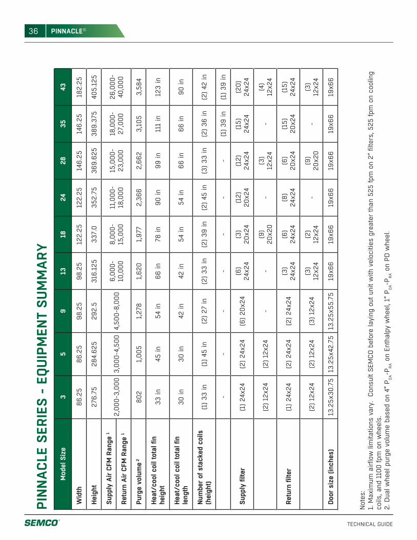
36
TECHNICAL GUIDE
PINNACLE®
PINN
ACLE
SER
IES
- EQ
UIPM
ENT
SUM
MAR
Y
Not
es:
1. M
axim
um a
irflo
w li
mita
tions
var
y. C
onsu
lt SE
MCO
bef
ore
layi
ng o
ut u
nit w
ith v
eloc
ities
gre
ater
than
525
fpm
on
2” fi
lters
, 525
fpm
on
cool
ing
coils
, and
110
0 fp
m o
n w
heel
s.2.
Dua
l whe
el p
urge
vol
ume
base
d on
4”
P OA-P
RA o
n En
thal
py w
heel
, 1”
P OA-P
RA o
n PD
whe
el.
Mod
el S
ize
35
913
1824
2835
43
Wid
th86
.25
86.2
598
.25
98.2
512
2.25
122.
2514
6.25
146.
2518
2.25
Heig
ht27
6.75
284.
625
292.
531
6.12
533
7.0
352.
7536
9.62
538
9.37
540
5.12
5
Supp
ly A
ir CF
M R
ange
1
2,00
0-3,
000
3,00
0-4,
500
4,50
0-8,
000
6,00
0-10
,000
8,00
0-15
,000
11,0
00-
18,0
0015
,000
-23
,000
18,0
00-
27,0
0026
,000
-40
,000
Retu
rn A
ir CF
M R
ange
1
Purg
e vo
lum
e 280
21,
005
1,27
81,
620
1,97
72,
366
2,66
23,
105
3,58
4
Heat
/coo
l coi
l tot
al fi
n he
ight
33 in
45 in
54 in
66 in
78 in
90 in
99 in
111
in12
3 in
Heat
/coo
l coi
l tot
al fi
n le
ngth
30 in
30 in
42 in
42 in
54 in
54 in
66 in
66 in
90 in
Num
ber o
f sta
cked
coi
ls
(hei
ght)
(1) 3
3 in
(1) 4
5 in
(2) 2
7 in
(2) 3
3 in
(2) 3
9 in
(2) 4
5 in
(3) 3
3 in
(2) 3
6 in
(2) 4
2 in
--
--
--
-(1
) 39
in(1
) 39
in
Supp
ly fi
lter
(1) 2
4x24
(2) 2
4x24
(6) 2
0x24
(6)
24x2
4(3
) 20
x24
(12)
20
x24
(12)
24
x24
(15)
24
x24
(20)
24
x24
(2) 1
2x24
(2) 1
2x24
--
(9)
20x2
0-
(3)
12x2
4-
(4)
12x2
4
Retu
rn fi
lter
(1) 2
4x24
(2) 2
4x24
(2) 2
4x24
(3)
24x2
4(6
) 24
x24
(8)
24x2
4(6
) 20
x24
(15)
20
x24
(15)
24
x24
(2) 1
2x24
(2) 1
2x24
(3) 1
2x24
(3)
12x2
4(2
) 12
x24
-(9
) 20
x20
-(3
) 12
x24
Door
siz
e (in
ches
)13
.25x
30.7
513
.25x
42.7
513
.25x
55.7
519
x66
19x6
619
x66
19x6
619
x66
19x6
6

37
TECHNICAL GUIDE
PINNACLE®

SEM
CO P
inna
cle
Tech
nica
l Gui
de
ww
w.s
emco
hvac
.com
WWW.SEMCOHVAC.COM | Pinnacle Technical Guide | 20151026
SEMCO embraces a policy of continuous development and improvement, the right is reserved to supply products which may differ from those illustrated and described in this
publication. Certified dimensions will be supplied upon request on receipt of order.
© SEMCO LLC 2015 All Rights Reserved. PINNACLE and the SEMCO logo are registered Trademarks of SEMCO LLC.
WE BRINGAIR TO LIFE
WE BRING AIR TO LIFE
SEMCO® is a global leader in air
management. We specialize in the
design and manufacture of a wide
range of air climate and air movement
solutions. Our collective experience
is unrivaled.
Our constant aim is to provide systems that
precisely deliver the best indoor air quality
and performance, as well as maximize
energy efficiency.
SEMCO® A Fläkt Woods CompanyCorporate Headquarters1800 East Pointe Drive
Columbia, Missouri 65201 USA
573 443 1481
To learn more about SEMCO offerings and to contact your nearest representative please visit www.semcohvac.com
Recommended