Physical Sciences 3 Wed 1-2 and Wed 2-3 sections TF: Widagdo Setiawan Practice Problems for Midterm Exam 2
Notes:
Original source of the problems: o http://ocw.mit.edu/courses/physics/8-02-electricity-and-magnetism-spring-
2002/exams/
o http://6004.csail.mit.edu/currentsemester/tutprobs/tutprobs.htm
o PS3 Website
o Problems in General Physics (I. E. Irodov)
Some of the problems are marked as “important”. These problems (or something similar) have a
high probability to be on the exam.
Most of these problems are harder than the exam problems. The idea is that if you can do these
problems, you should be able to do the exam problems too.
Since the problems are hard, it is ok to read the solution immediately after you read the
problems. However, after you read the solution, you should actually do the problem from
scratch without looking at the solution. If you get stuck, then you can check the solution again,
but in the end you should try to do the problems from scratch completely without the solution.
If the solutions for some problems are either not clear or too short, please email me. I will gladly
expand the solutions.
I wrote the solution from scratch myself, so it is entirely possible that I made some mistakes on
the solution. Please let me know if you see some possible errors.
1. Consider the following circuit:
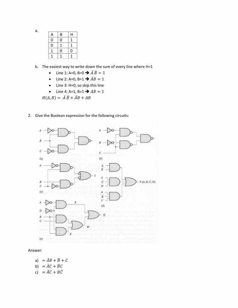
a. Write down the truth table
b. Write down the Boolean expression for H(A,B)
Answer:
a.
b. The easiest way to write down the sum of every line where H=1
Line 1: A=0, B=0
Line 2: A=0, B=1
Line 3: H=0, so skip this line
Line 4: A=1, B=1
( )
2. Give the Boolean expression for the following circuits:
Answer:
a)
b)
c)
A B H
0 0 1
0 1 1
1 0 0
1 1 1
d)
e)
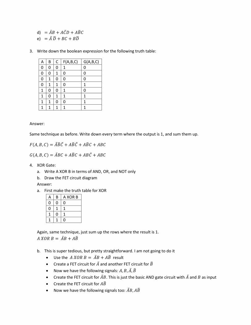
3. Write down the boolean expression for the following truth table:
A B C F(A,B,C) G(A,B,C)
0 0 0 1 0
0 0 1 0 0
0 1 0 0 0
0 1 1 0 1
1 0 0 1 0
1 0 1 1 1
1 1 0 0 1
1 1 1 1 1
Answer:
Same technique as before. Write down every term where the output is 1, and sum them up.
( )
( )
4. XOR Gate:
a. Write A XOR B in terms of AND, OR, and NOT only
b. Draw the FET circuit diagram
Answer:
a. First make the truth table for XOR
A B A XOR B
0 0 0
0 1 1
1 0 1
1 1 0
Again, same technique, just sum up the rows where the result is 1.
b. This is super tedious, but pretty straightforward. I am not going to do it
Use the result
Create a FET circuit for and another FET circuit for
Now we have the following signals:
Create the FET circuit for . This is just the basic AND gate circuit with and as input
Create the FET circuit for
Now we have the following signals too:
Create a FET circuit for . This is just the basic OR gate circuit with and as
input
You are done
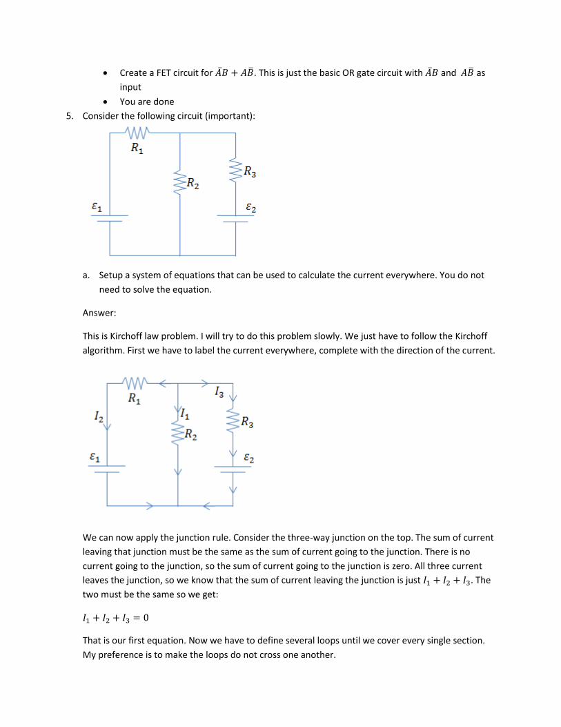
5. Consider the following circuit (important):
a. Setup a system of equations that can be used to calculate the current everywhere. You do not
need to solve the equation.
Answer:
This is Kirchoff law problem. I will try to do this problem slowly. We just have to follow the Kirchoff
algorithm. First we have to label the current everywhere, complete with the direction of the current.
We can now apply the junction rule. Consider the three-way junction on the top. The sum of current
leaving that junction must be the same as the sum of current going to the junction. There is no
current going to the junction, so the sum of current going to the junction is zero. All three current
leaves the junction, so we know that the sum of current leaving the junction is just . The
two must be the same so we get:
That is our first equation. Now we have to define several loops until we cover every single section.
My preference is to make the loops do not cross one another.
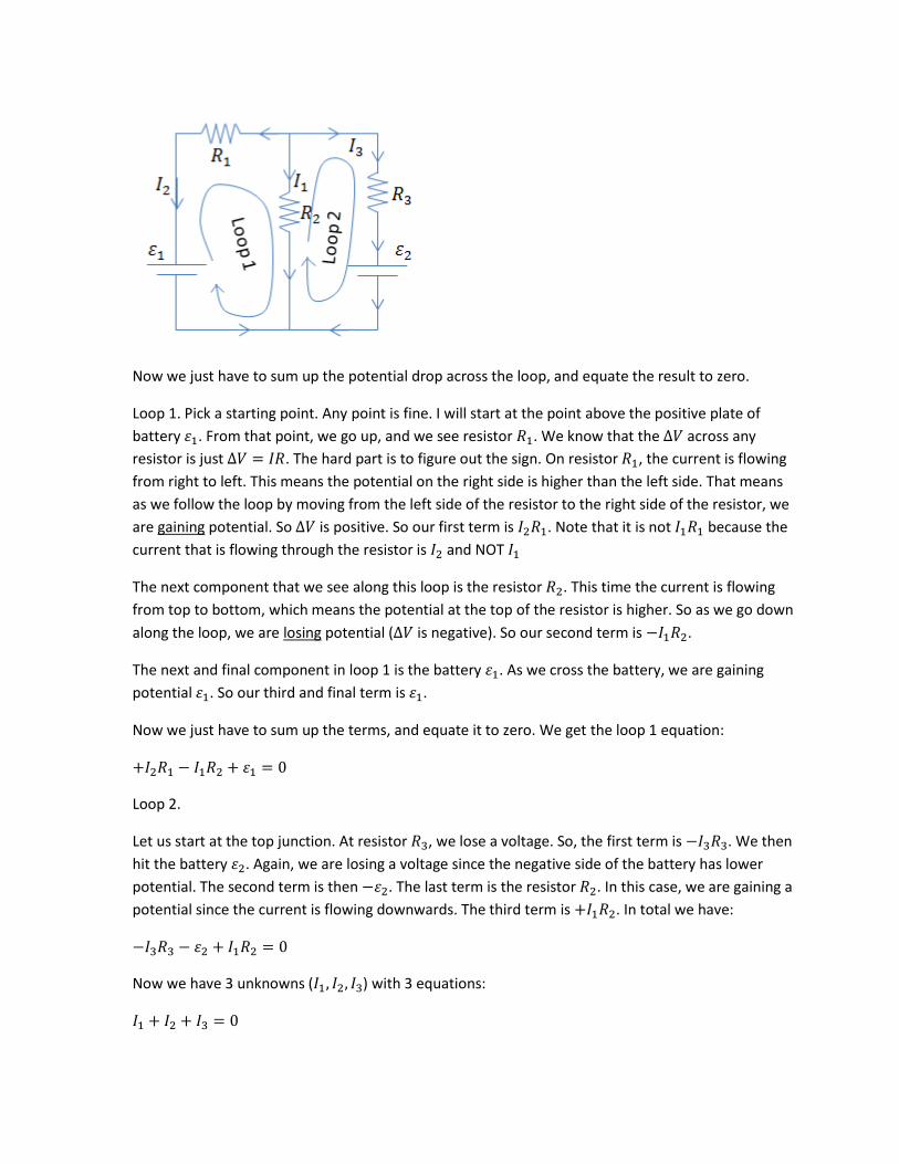
Now we just have to sum up the potential drop across the loop, and equate the result to zero.
Loop 1. Pick a starting point. Any point is fine. I will start at the point above the positive plate of
battery . From that point, we go up, and we see resistor . We know that the across any
resistor is just . The hard part is to figure out the sign. On resistor , the current is flowing
from right to left. This means the potential on the right side is higher than the left side. That means
as we follow the loop by moving from the left side of the resistor to the right side of the resistor, we
are gaining potential. So is positive. So our first term is . Note that it is not because the
current that is flowing through the resistor is and NOT
The next component that we see along this loop is the resistor . This time the current is flowing
from top to bottom, which means the potential at the top of the resistor is higher. So as we go down
along the loop, we are losing potential ( is negative). So our second term is .
The next and final component in loop 1 is the battery . As we cross the battery, we are gaining
potential . So our third and final term is .
Now we just have to sum up the terms, and equate it to zero. We get the loop 1 equation:
Loop 2.
Let us start at the top junction. At resistor , we lose a voltage. So, the first term is . We then
hit the battery . Again, we are losing a voltage since the negative side of the battery has lower
potential. The second term is then . The last term is the resistor . In this case, we are gaining a
potential since the current is flowing downwards. The third term is . In total we have:
Now we have 3 unknowns ( ) with 3 equations:
Solving the equation is tedious and I will not do it here.
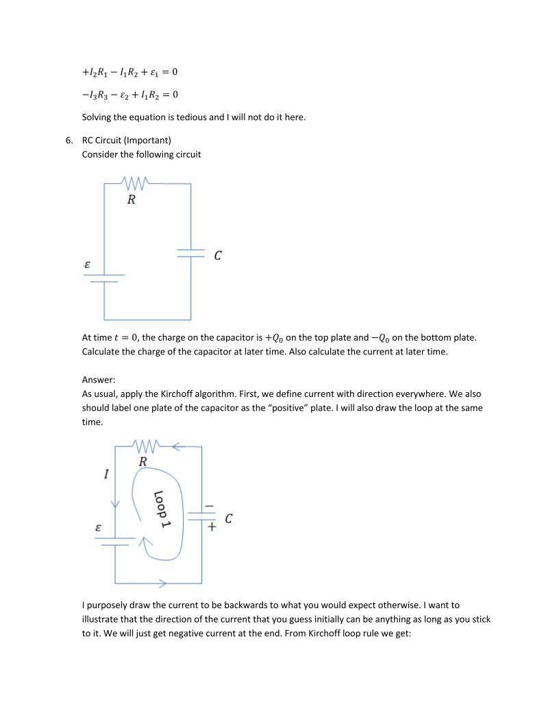
6. RC Circuit (Important)
Consider the following circuit
At time , the charge on the capacitor is on the top plate and on the bottom plate.
Calculate the charge of the capacitor at later time. Also calculate the current at later time.
Answer:
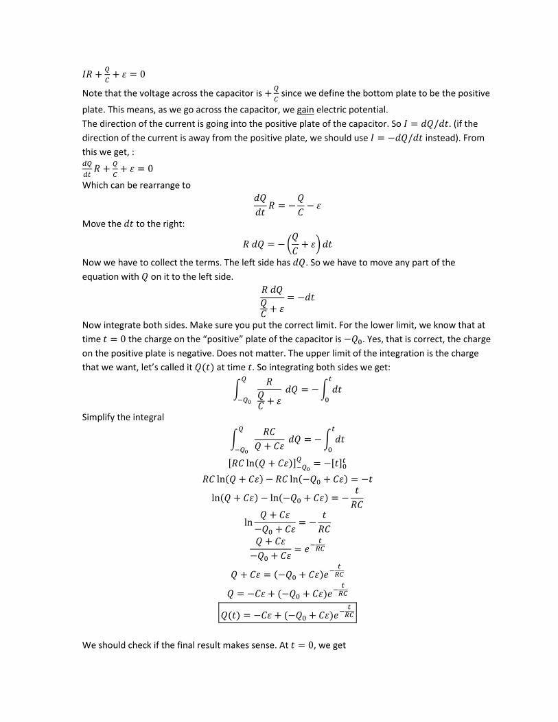
As usual, apply the Kirchoff algorithm. First, we define current with direction everywhere. We also
should label one plate of the capacitor as the “positive” plate. I will also draw the loop at the same
time.
I purposely draw the current to be backwards to what you would expect otherwise. I want to
illustrate that the direction of the current that you guess initially can be anything as long as you stick
to it. We will just get negative current at the end. From Kirchoff loop rule we get:
Note that the voltage across the capacitor is
since we define the bottom plate to be the positive
plate. This means, as we go across the capacitor, we gain electric potential.
The direction of the current is going into the positive plate of the capacitor. So . (if the
direction of the current is away from the positive plate, we should use instead). From
this we get, :
Which can be rearrange to
Move the to the right:
(
)
Now we have to collect the terms. The left side has . So we have to move any part of the
equation with on it to the left side.
Now integrate both sides. Make sure you put the correct limit. For the lower limit, we know that at
time the charge on the “positive” plate of the capacitor is . Yes, that is correct, the charge
on the positive plate is negative. Does not matter. The upper limit of the integration is the charge
that we want, let’s called it ( ) at time . So integrating both sides we get:
∫
∫
Simplify the integral
∫
∫
[ ( )] [ ]
( ) ( )
( ) ( )
( )
( )
( ) ( )
We should check if the final result makes sense. At , we get
( )
That equation means that the charge on the “positive” plate of the capacitor is . This is exactly
what the problem specified. The charge of the bottom plate of the capacitor is at .
Another thing we can check is at . We get
( )
The charge at the positive plate at far future is – . This make sense since at far future, the current
through the resistor must be zero. So the voltage of the capacitor must be the same as the voltage
of the battery. We expect that the top plate of the capacitor to have charge while the charge
on the bottom plate is – , which is exactly what we get from our solution. So our answer is
probably correct.
Now we have to calculate the current. From our equation above,
. We get
( )
( )
7. A mass spectrometer accelerates doubly ionized atoms over a potential difference before they
enter a uniform magnetic field which is perpendicular to the direction of motion of the ions. If is
the radius of the ions’ path in the magnetic field, what is the mass of one ion?
Answer:
If we assume that the ions start at rest, the total kinetic energy after being accelerated by potential
difference is . Note that although a doubly ionized ions has charge of , the kinetic
energy is always positive. From there, using
, we can deduce the velocity of the ions,
which is √
√
. This is the velocity of the ions as they enter the magnetic field region.
Now in the magnetic field region, they will experience Lorentz force, , where is the
charge of the particle, which is (I know that the charge is , but I prefer to figure out the
direction at the very end. On the exam, you should write something like “I will figure out the
direction later” in order not to lose points). Note that the formula for the force above is only valid if
the velocity is perpendicular to the magnetic field. Since the force is always perpendicular to the
velocity of the ions, the ions will move in circular motion. We can calculate the radius of this circular
motion by using the centripetal force
. Equation the two equations for the force we get
From the problem, we know that the radius of the path is , so . We want to find out the mass
of the ions. We get
√
√
√
You might be tempted that you already get the correct answer there, but remember, they are asking
for the mass , so your answer cannot contain too! So we have to eliminate on the right side.
√ √
Now our answer only depends on the variables given in the problem ( ) and fundamental
constant ( ), so we are done. We do not even have to figure out the direction of the force for this
problem.
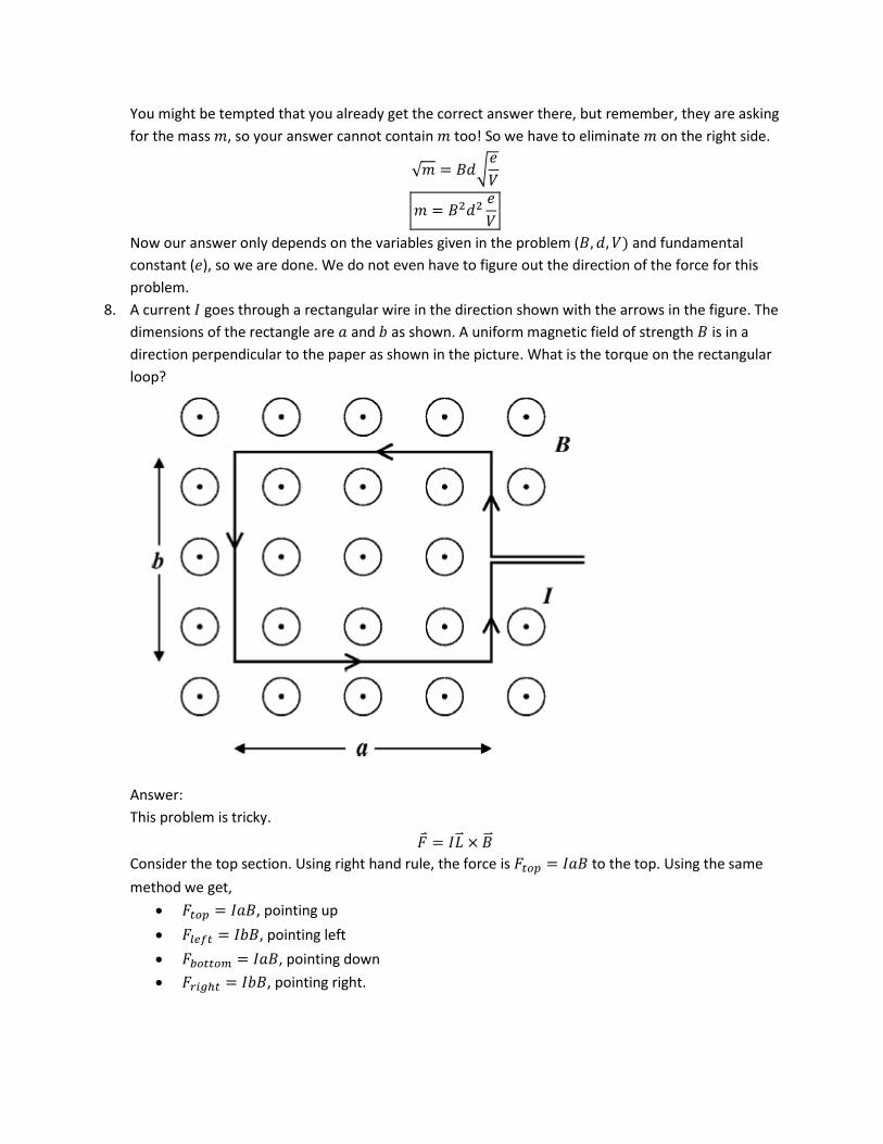
8. A current goes through a rectangular wire in the direction shown with the arrows in the figure. The
dimensions of the rectangle are and as shown. A uniform magnetic field of strength is in a
direction perpendicular to the paper as shown in the picture. What is the torque on the rectangular
loop?
Answer:
This problem is tricky.
Consider the top section. Using right hand rule, the force is to the top. Using the same
method we get,
, pointing up
, pointing left
, pointing down
, pointing right.
The forces and cancel. Similarly, and cancel. So the net force is zero. But
wait, they are asking you about the torque, not the force. Remember that even though the force is
zero, the torque could be non-zero.
To define a torque, we need to define an origin. This is a very important step. You can define force
without any origin, but you can NOT define torque without any origin. The origin can be any point in
the system, but you have to make it clear where the origin is. Generally, the torque will depend on
the choice of the origin. The only exception is when the total force is zero, like this problem. In this
case, the torque is the same independent of the origin.
is the vector from the origin to the location of the force. The cross product means that only the
perpendicular (perpendicular to the force) component of matters in the final torque.
Let us pick the center of the rectangle as the origin for calculating torque. For calculating the torque
of the left section, we draw the from the origin to the left section. The direction of the force on
the left section is to the left, which is the same direction as . Therefore, the torque contribution of
this section is zero. Similarly, the torque contributions from the other 3 sections are also zero.
Therefore, the total torque on the wire is zero.
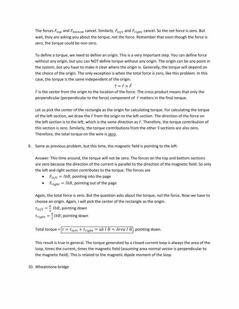
9. Same as previous problem, but this time, the magnetic field is pointing to the left.
Answer: This time around, the torque will not be zero. The forces on the top and bottom sections
are zero because the direction of the current is parallel to the direction of the magnetic field. So only
the left and right section contributes to the torque. The forces are
, pointing into the page
, pointing out of the page
Again, the total force is zero. But the question asks about the torque, not the force. Now we have to
choose an origin. Again, I will pick the center of the rectangle as the origin.
, pointing down
, pointing down
Total torque = , pointing down.
This result is true in general. The torque generated by a closed current loop is always the area of the
loop, times the current, times the magnetic field (assuming area normal vector is perpendicular to
the magnetic field). This is related to the magnetic dipole moment of the loop.
10. Wheatstone bridge
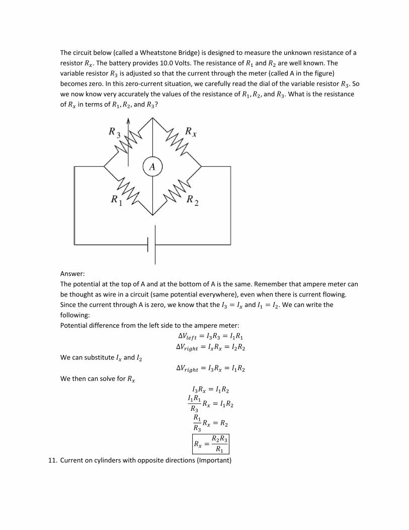
The circuit below (called a Wheatstone Bridge) is designed to measure the unknown resistance of a
resistor . The battery provides 10.0 Volts. The resistance of and are well known. The
variable resistor is adjusted so that the current through the meter (called A in the figure)
becomes zero. In this zero-current situation, we carefully read the dial of the variable resistor . So
we now know very accurately the values of the resistance of and . What is the resistance
of in terms of and ?
Answer:
The potential at the top of A and at the bottom of A is the same. Remember that ampere meter can
be thought as wire in a circuit (same potential everywhere), even when there is current flowing.
Since the current through A is zero, we know that the and . We can write the
following:
Potential difference from the left side to the ampere meter:
We can substitute and
We then can solve for
11. Current on cylinders with opposite directions (Important)
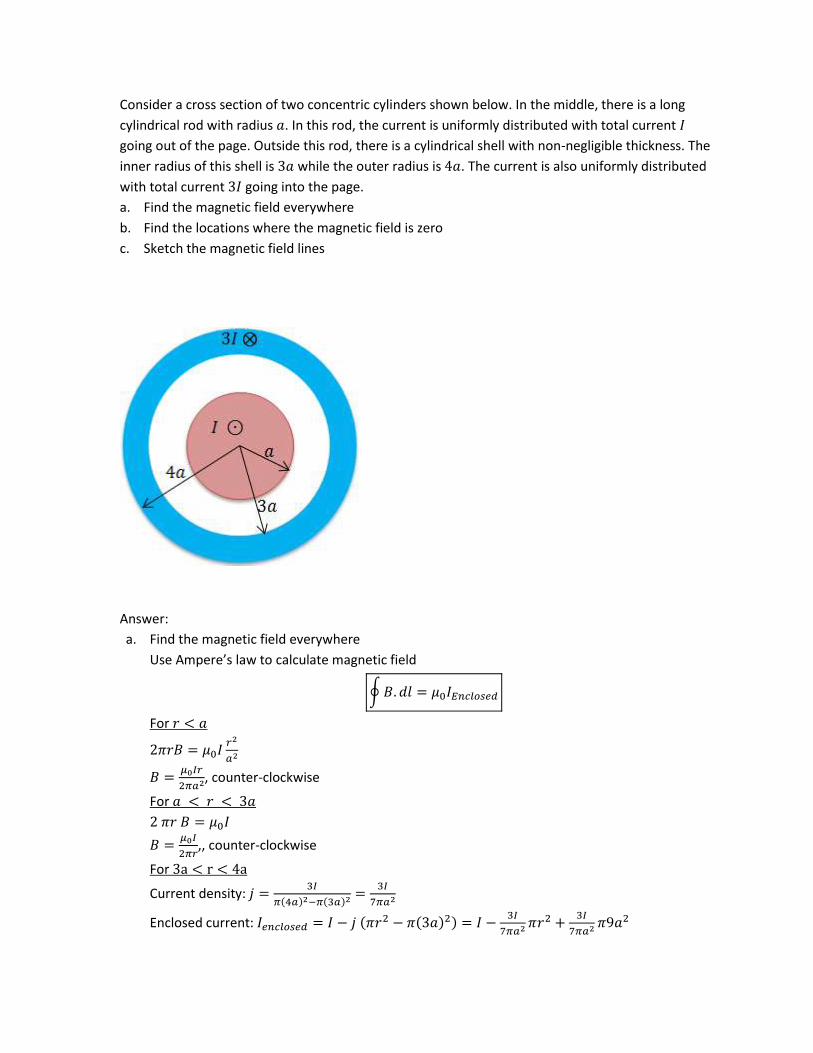
Consider a cross section of two concentric cylinders shown below. In the middle, there is a long
cylindrical rod with radius . In this rod, the current is uniformly distributed with total current
going out of the page. Outside this rod, there is a cylindrical shell with non-negligible thickness. The
inner radius of this shell is while the outer radius is . The current is also uniformly distributed
with total current going into the page.
a. Find the magnetic field everywhere
b. Find the locations where the magnetic field is zero
c. Sketch the magnetic field lines
Answer:
a. Find the magnetic field everywhere
Use Ampere’s law to calculate magnetic field
∮
For
, counter-clockwise
For
,, counter-clockwise
For
Current density:
( ) ( )
Enclosed current: ( ( ) )
Apply Amplere’s Law
(
), counter-clockwise. Note that at some point the magnitude
become negative. When , the direction is actually clockwise.
For
, clockwise
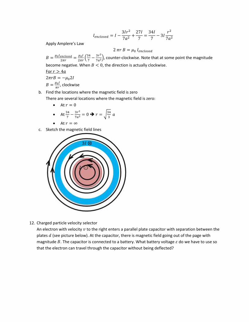
b. Find the locations where the magnetic field is zero
There are several locations where the magnetic field is zero:
At
At
√
At
c. Sketch the magnetic field lines
12. Charged particle velocity selector
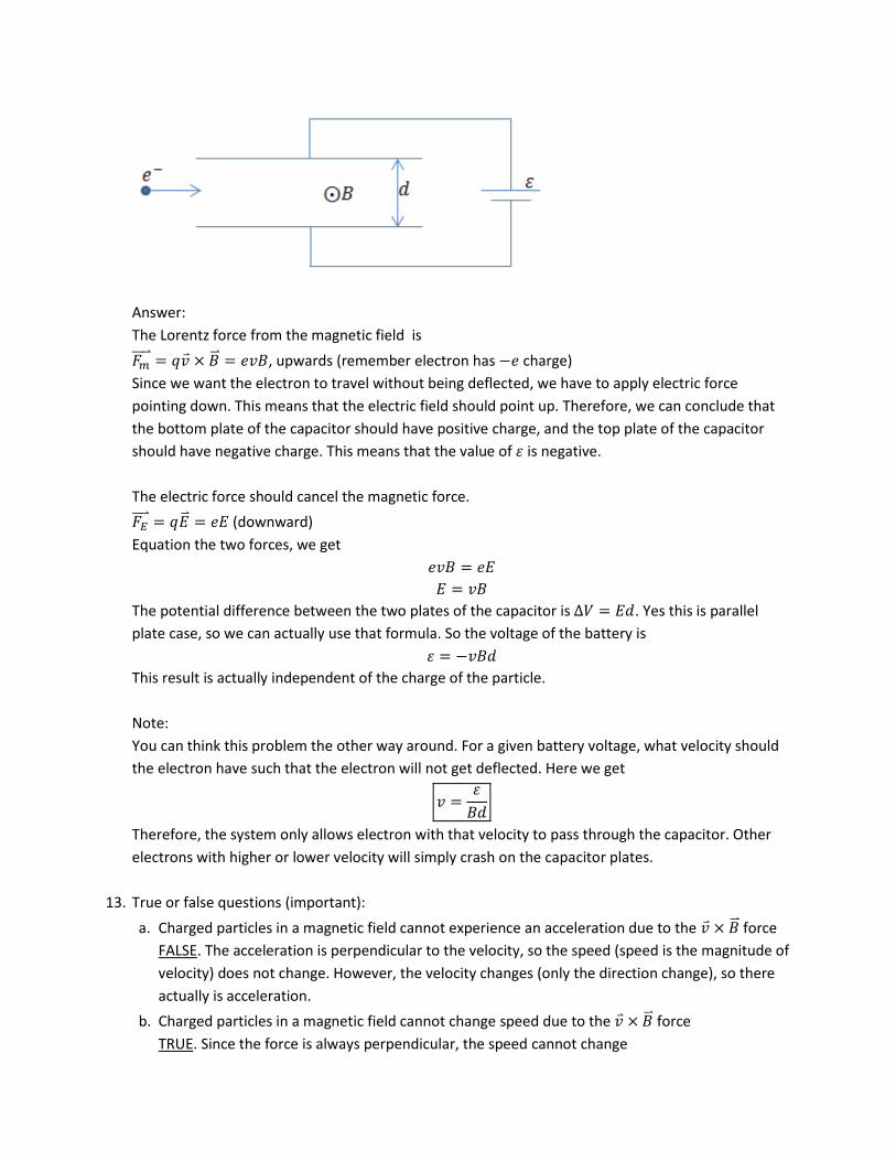
An electron with velocity to the right enters a parallel plate capacitor with separation between the
plates (see picture below). At the capacitor, there is magnetic field going out of the page with
magnitude . The capacitor is connected to a battery. What battery voltage do we have to use so
that the electron can travel through the capacitor without being deflected?
Answer:
The Lorentz force from the magnetic field is
, upwards (remember electron has charge)
Since we want the electron to travel without being deflected, we have to apply electric force
pointing down. This means that the electric field should point up. Therefore, we can conclude that
the bottom plate of the capacitor should have positive charge, and the top plate of the capacitor
should have negative charge. This means that the value of is negative.
The electric force should cancel the magnetic force.
(downward)
Equation the two forces, we get
The potential difference between the two plates of the capacitor is . Yes this is parallel
plate case, so we can actually use that formula. So the voltage of the battery is
This result is actually independent of the charge of the particle.
Note:
You can think this problem the other way around. For a given battery voltage, what velocity should
the electron have such that the electron will not get deflected. Here we get
Therefore, the system only allows electron with that velocity to pass through the capacitor. Other
electrons with higher or lower velocity will simply crash on the capacitor plates.
13. True or false questions (important):
a. Charged particles in a magnetic field cannot experience an acceleration due to the force
FALSE. The acceleration is perpendicular to the velocity, so the speed (speed is the magnitude of
velocity) does not change. However, the velocity changes (only the direction change), so there
actually is acceleration.
b. Charged particles in a magnetic field cannot change speed due to the force
TRUE. Since the force is always perpendicular, the speed cannot change
c. A positive charge and a negative charge turn in the opposite direction under uniform magnetic
field
TRUE. The force has opposite signs
d. Magnetic field lines start at the north pole of a magnet, and end at the south pole of the magnet
FALSE. This is a trick question. Magnetic field cannot start and end anywhere. They always form
loops.
e. The magnetic south pole of the earth is located near the earth’s north pole
TRUE. This is the reason why compass points north: the north pole of the compass is attracted
to the earth’s magnetic south pole, close to the geographical north pole.
f. Magnetic field lines go from the south pole to the north pole inside a magnet.
TRUE. This is the only way we can close the magnetic field lines to form loops
g. NASA’s tether experiment generated electric power by moving a very long conducting wire
(attached to the shuttle) through the Earth’s magnetic field. The electric energy that was
generated was at the expense of the kinetic energy (thus speed) of the shuttle.
TRUE. The current generated by the induced EMF actually create a force that slows down the
wire, thus the shuttle
h. When a magnetic flux through a conducting loop is zero, there cannot be an induced EMF in that
loop
FALSE. EMF is generated by the change of magnetic flux. Just because the magnetic flux is zero,
does not mean that the change of flux is zero.
i.
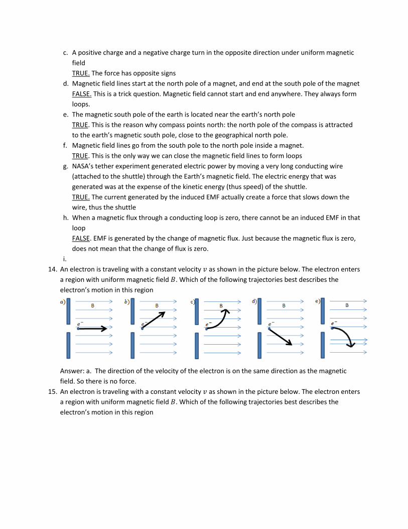
14. An electron is traveling with a constant velocity as shown in the picture below. The electron enters
a region with uniform magnetic field . Which of the following trajectories best describes the
electron’s motion in this region
Answer: a. The direction of the velocity of the electron is on the same direction as the magnetic
field. So there is no force.
15. An electron is traveling with a constant velocity as shown in the picture below. The electron enters
a region with uniform magnetic field . Which of the following trajectories best describes the
electron’s motion in this region
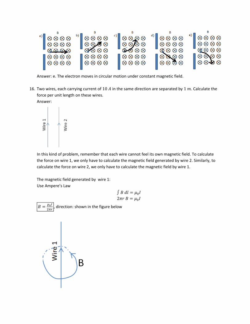
Answer: e. The electron moves in circular motion under constant magnetic field.
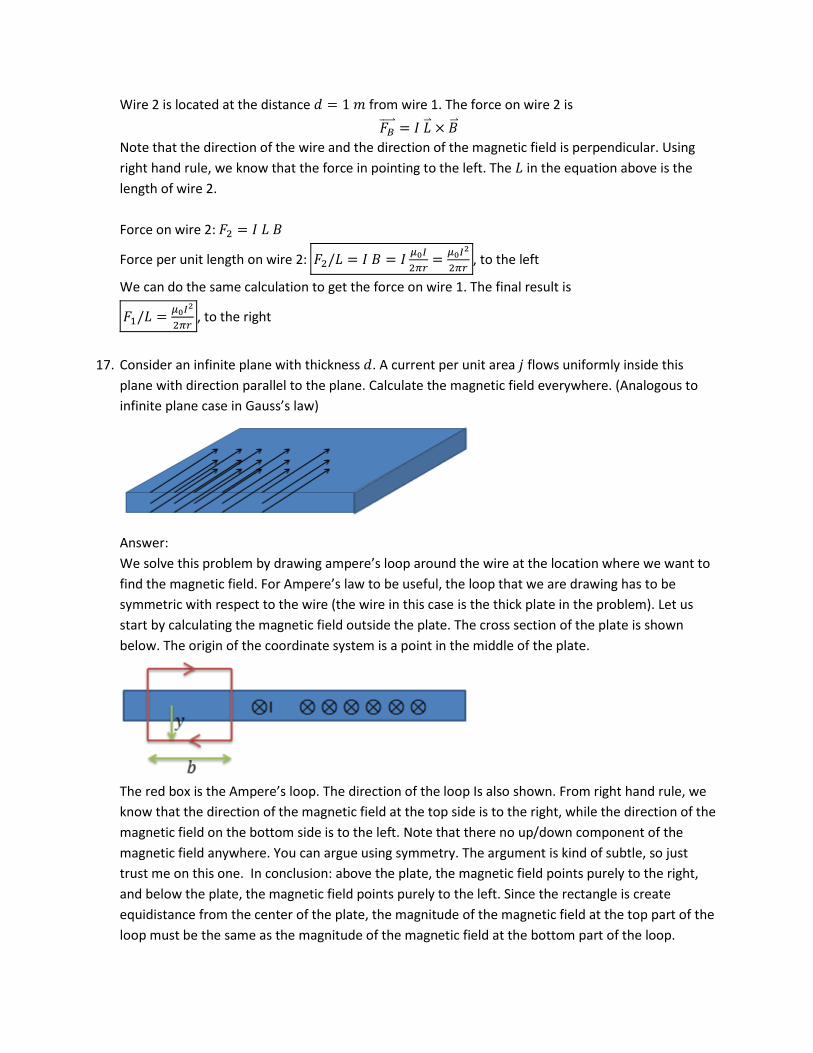
16. Two wires, each carrying current of in the same direction are separated by . Calculate the
force per unit length on these wires.
Answer:
In this kind of problem, remember that each wire cannot feel its own magnetic field. To calculate
the force on wire 1, we only have to calculate the magnetic field generated by wire 2. Similarly, to
calculate the force on wire 2, we only have to calculate the magnetic field by wire 1.
The magnetic field generated by wire 1:
Use Ampere’s Law
, direction: shown in the figure below
Wire 2 is located at the distance from wire 1. The force on wire 2 is
Note that the direction of the wire and the direction of the magnetic field is perpendicular. Using
right hand rule, we know that the force in pointing to the left. The in the equation above is the
length of wire 2.
Force on wire 2:
Force per unit length on wire 2:
, to the left
We can do the same calculation to get the force on wire 1. The final result is
, to the right
17. Consider an infinite plane with thickness . A current per unit area flows uniformly inside this
plane with direction parallel to the plane. Calculate the magnetic field everywhere. (Analogous to
infinite plane case in Gauss’s law)
Answer:
We solve this problem by drawing ampere’s loop around the wire at the location where we want to
find the magnetic field. For Ampere’s law to be useful, the loop that we are drawing has to be
symmetric with respect to the wire (the wire in this case is the thick plate in the problem). Let us
start by calculating the magnetic field outside the plate. The cross section of the plate is shown
below. The origin of the coordinate system is a point in the middle of the plate.
The red box is the Ampere’s loop. The direction of the loop Is also shown. From right hand rule, we
know that the direction of the magnetic field at the top side is to the right, while the direction of the
magnetic field on the bottom side is to the left. Note that there no up/down component of the
magnetic field anywhere. You can argue using symmetry. The argument is kind of subtle, so just
trust me on this one. In conclusion: above the plate, the magnetic field points purely to the right,
and below the plate, the magnetic field points purely to the left. Since the rectangle is create
equidistance from the center of the plate, the magnitude of the magnetic field at the top part of the
loop must be the same as the magnitude of the magnetic field at the bottom part of the loop.
We can now apply Ampere’s law
Let us evaluate the left side of the equation. We can split the integral into 4 parts:
Left part of the loop: , since the magnetic field points perpendicular to the loop
direction
Top part of the loop: since the magnetic field, , the parallel to the loop
Right part of the loop: , since the magnetic field is perpendicular to the loop
Bottom part of the loop: , since the magnetic field is parallel to the loop.
In total, .
Now we evaluate the right side of the equation, which is just calculating how much current is
enclosed by the loop. The enclosed current is just the current per unit area, , multiplied by the
enclosed area .
Combining the two sides of the equation
, to the right on top of the plate, and to the left under the plate
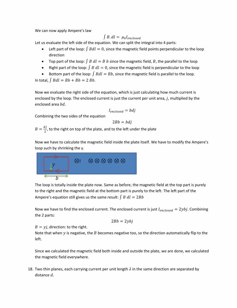
Now we have to calculate the magnetic field inside the plate itself. We have to modify the Ampere’s
loop such by shrinking the y.
The loop is totally inside the plate now. Same as before, the magnetic field at the top part is purely
to the right and the magnetic field at the bottom part is purely to the left. The left part of the
Ampere’s equation still gives us the same result:
Now we have to find the enclosed current. The enclosed current is just . Combining
the 2 parts:
direction: to the right.
Note that when is negative, the becomes negative too, so the direction automatically flip to the
left.
Since we calculated the magnetic field both inside and outside the plate, we are done, we calculated
the magnetic field everywhere.
18. Two thin planes, each carrying current per unit length in the same direction are separated by
distance .
a. Calculate the magnetic field everywhere
b. Calculate the pressure on each plane.
Answer:
Part a
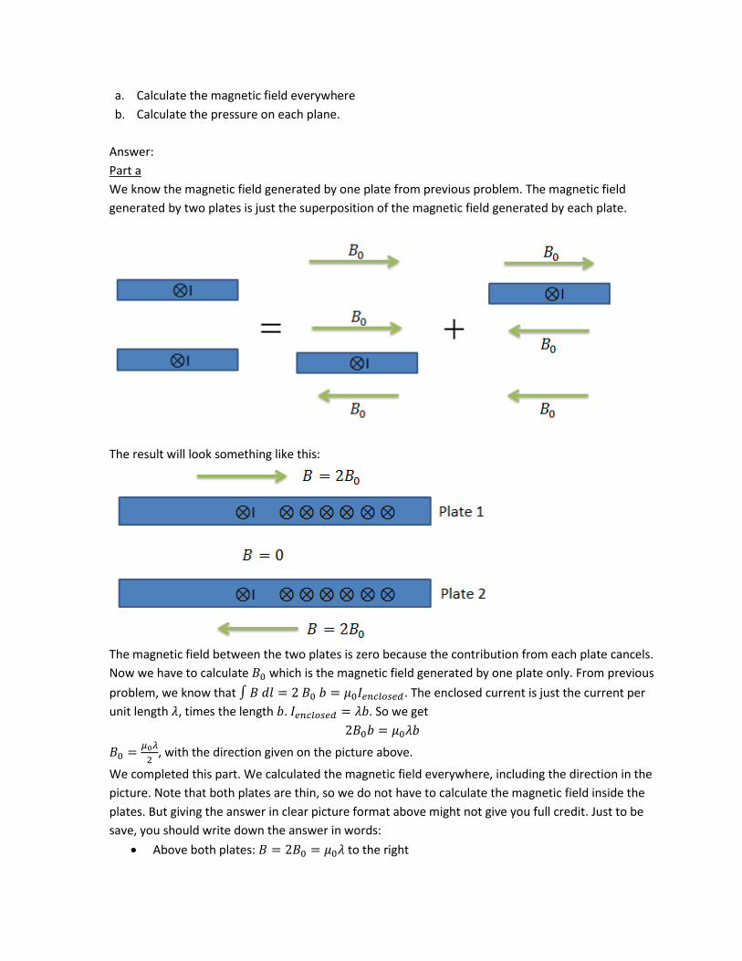
We know the magnetic field generated by one plate from previous problem. The magnetic field
generated by two plates is just the superposition of the magnetic field generated by each plate.
The result will look something like this:
The magnetic field between the two plates is zero because the contribution from each plate cancels.
Now we have to calculate which is the magnetic field generated by one plate only. From previous
problem, we know that . The enclosed current is just the current per
unit length , times the length . . So we get
, with the direction given on the picture above.
We completed this part. We calculated the magnetic field everywhere, including the direction in the
picture. Note that both plates are thin, so we do not have to calculate the magnetic field inside the
plates. But giving the answer in clear picture format above might not give you full credit. Just to be
save, you should write down the answer in words:
Above both plates: to the right
Between the two plates:
Below both plates to the left.
Part b
First, let us calculate the force on each plate. Remember, when we calculate force, we cannot
include the magnetic field generated by the object in question. So to calculate the force on plate 1,
we can only include the magnetic field generated by plate 2.
The magnetic field at the location of plate 1 generated by plate 2 is pointing to the right. The
force on plate 1 is . Note that the direction of the current is perpendicular to the direction
of the magnetic field, so we can just multiply and . The direction of the force is going up using
the right hand rule. The in the equation above is the current of plate 1. This current is
where is the length of plate 1 in the x direction. The in the force equation above is the length of
plate 1 in the direction of the current (let’s called it z) so . Putting this together
is just the area of plate one. So we can define .
Pressure is just force per unit area . So we get
So there is a pressure that wants to make the two plates crash toward each other.
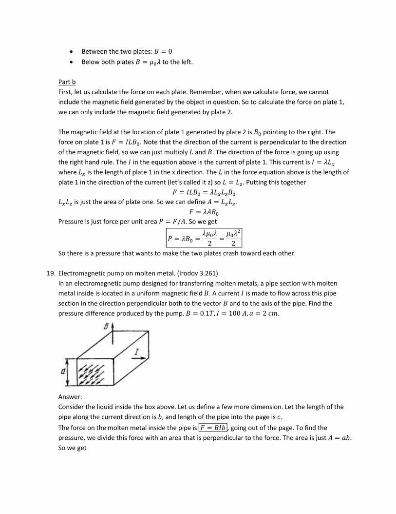
19. Electromagnetic pump on molten metal. (Irodov 3.261)
In an electromagnetic pump designed for transferring molten metals, a pipe section with molten
metal inside is located in a uniform magnetic field . A current is made to flow across this pipe
section in the direction perpendicular both to the vector and to the axis of the pipe. Find the
pressure difference produced by the pump. .
Answer:
Consider the liquid inside the box above. Let us define a few more dimension. Let the length of the
pipe along the current direction is , and length of the pipe into the page is .
The force on the molten metal inside the pipe is , going out of the page. To find the
pressure, we divide this force with an area that is perpendicular to the force. The area is just .
So we get
So the magnetic force pushes the molten metal out of the page. Not that this is NOT how must
pump work. For this pump to work, the liquid being pushed around must be conductive since we
have to flow current through the liquid itself. Most liquid is not conductive. So this pump works only
for something like molten metal as mentioned in the problem. One example where this kind of
pump is used is inside nuclear submarine where they want to limit the noise emitted by the pump.
This pump produce very little noise since there is no moving part except for the liquid being pumped.
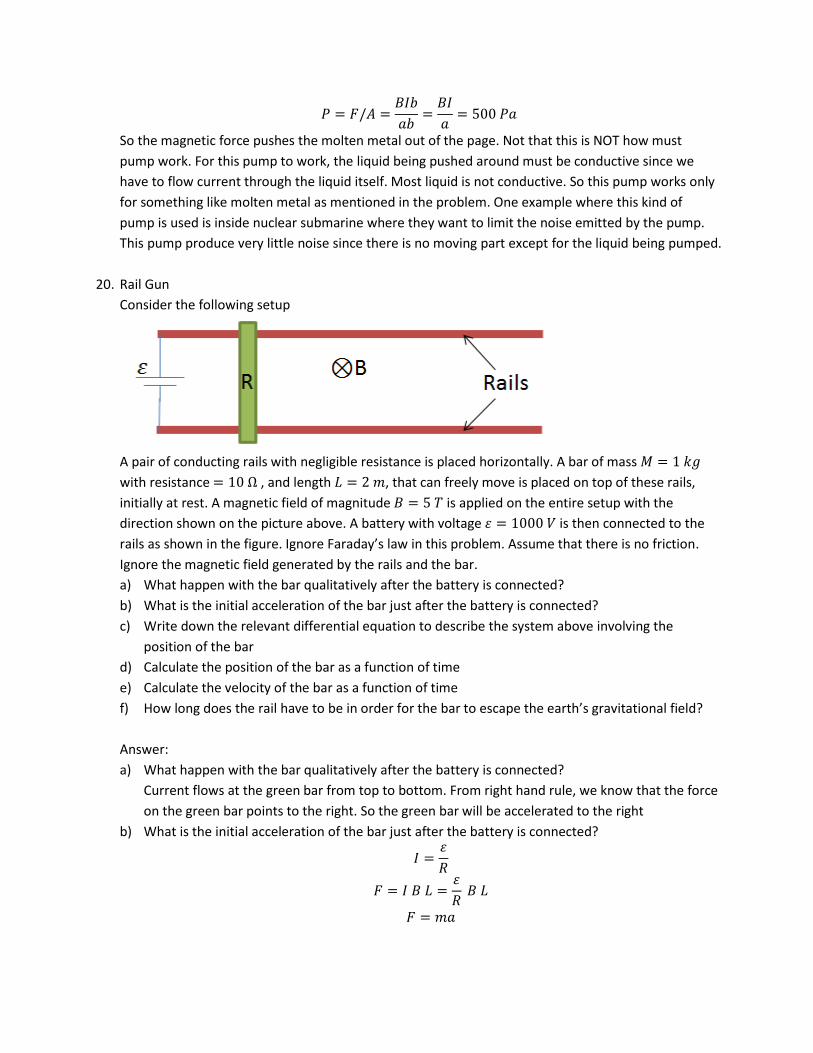
20. Rail Gun
Consider the following setup
A pair of conducting rails with negligible resistance is placed horizontally. A bar of mass
with resistance , and length , that can freely move is placed on top of these rails,
initially at rest. A magnetic field of magnitude is applied on the entire setup with the
direction shown on the picture above. A battery with voltage is then connected to the
rails as shown in the figure. Ignore Faraday’s law in this problem. Assume that there is no friction.
Ignore the magnetic field generated by the rails and the bar.
a) What happen with the bar qualitatively after the battery is connected?
b) What is the initial acceleration of the bar just after the battery is connected?
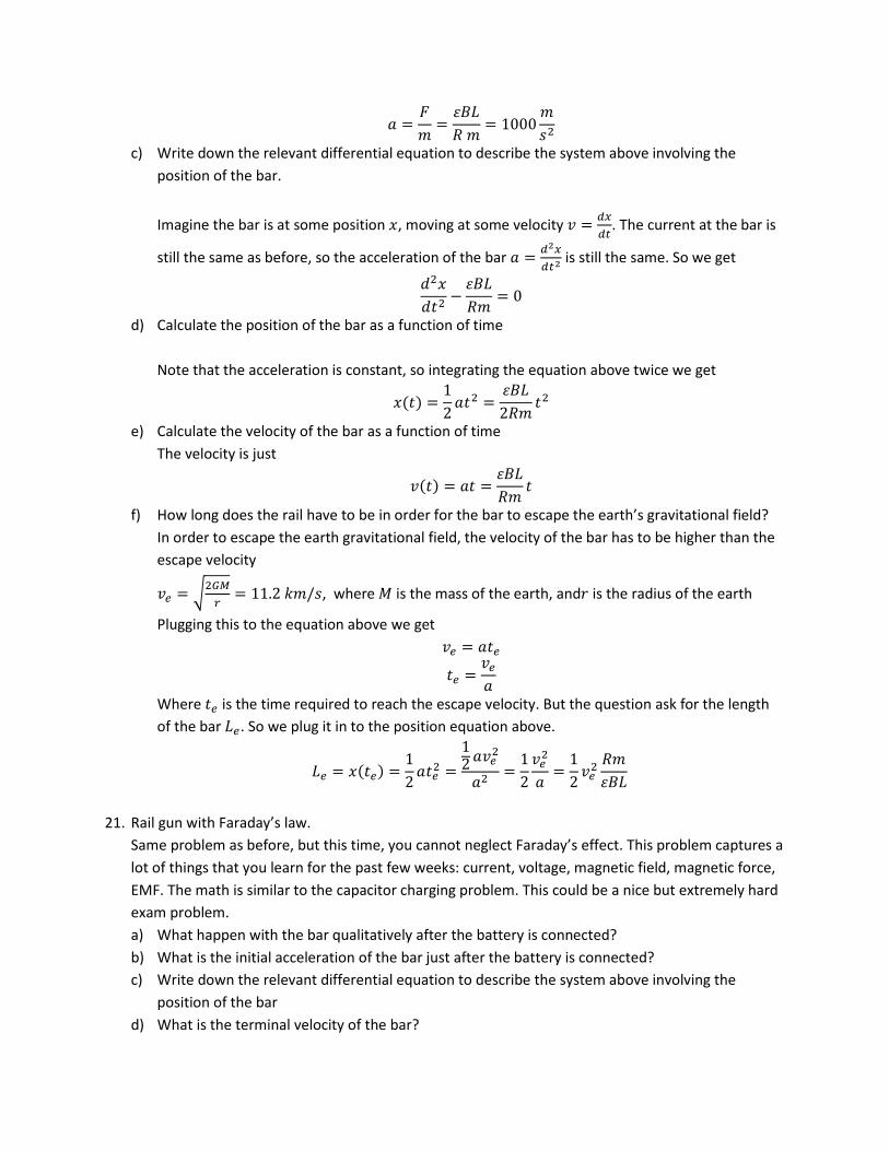
c) Write down the relevant differential equation to describe the system above involving the
position of the bar
d) Calculate the position of the bar as a function of time
e) Calculate the velocity of the bar as a function of time
f) How long does the rail have to be in order for the bar to escape the earth’s gravitational field?
Answer:
a) What happen with the bar qualitatively after the battery is connected?
Current flows at the green bar from top to bottom. From right hand rule, we know that the force
on the green bar points to the right. So the green bar will be accelerated to the right
b) What is the initial acceleration of the bar just after the battery is connected?
c) Write down the relevant differential equation to describe the system above involving the
position of the bar.
Imagine the bar is at some position , moving at some velocity
. The current at the bar is
still the same as before, so the acceleration of the bar
is still the same. So we get
d) Calculate the position of the bar as a function of time
Note that the acceleration is constant, so integrating the equation above twice we get
( )
e) Calculate the velocity of the bar as a function of time
The velocity is just
( )
f) How long does the rail have to be in order for the bar to escape the earth’s gravitational field?
In order to escape the earth gravitational field, the velocity of the bar has to be higher than the
escape velocity
√
, where is the mass of the earth, and is the radius of the earth
Plugging this to the equation above we get
Where is the time required to reach the escape velocity. But the question ask for the length
of the bar . So we plug it in to the position equation above.
( )
21. Rail gun with Faraday’s law.
Same problem as before, but this time, you cannot neglect Faraday’s effect. This problem captures a
lot of things that you learn for the past few weeks: current, voltage, magnetic field, magnetic force,
EMF. The math is similar to the capacitor charging problem. This could be a nice but extremely hard
exam problem.
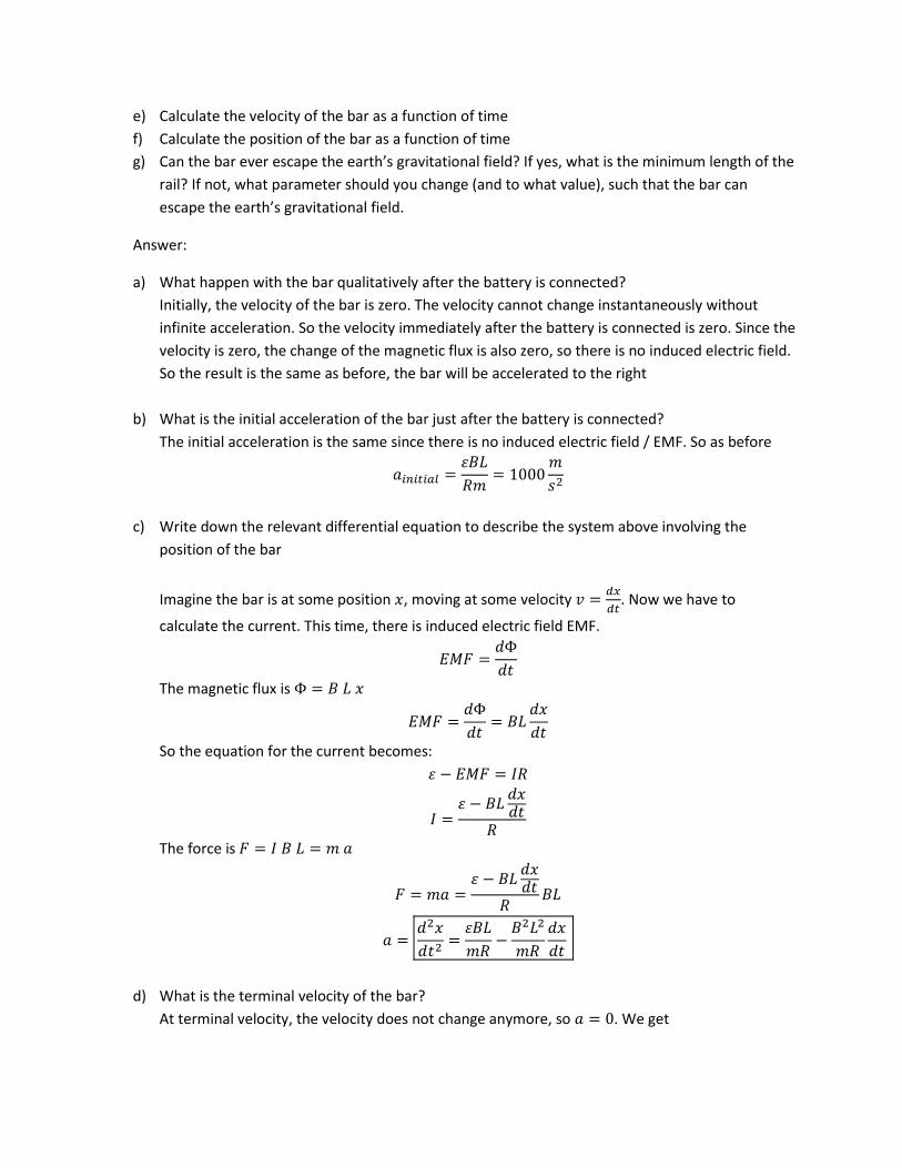
a) What happen with the bar qualitatively after the battery is connected?
b) What is the initial acceleration of the bar just after the battery is connected?
c) Write down the relevant differential equation to describe the system above involving the
position of the bar
d) What is the terminal velocity of the bar?
e) Calculate the velocity of the bar as a function of time
f) Calculate the position of the bar as a function of time
g) Can the bar ever escape the earth’s gravitational field? If yes, what is the minimum length of the
rail? If not, what parameter should you change (and to what value), such that the bar can
escape the earth’s gravitational field.
Answer:
a) What happen with the bar qualitatively after the battery is connected?
Initially, the velocity of the bar is zero. The velocity cannot change instantaneously without
infinite acceleration. So the velocity immediately after the battery is connected is zero. Since the
velocity is zero, the change of the magnetic flux is also zero, so there is no induced electric field.
So the result is the same as before, the bar will be accelerated to the right
b) What is the initial acceleration of the bar just after the battery is connected?
The initial acceleration is the same since there is no induced electric field / EMF. So as before
c) Write down the relevant differential equation to describe the system above involving the
position of the bar
Imagine the bar is at some position , moving at some velocity
. Now we have to
calculate the current. This time, there is induced electric field EMF.
The magnetic flux is
So the equation for the current becomes:
The force is
d) What is the terminal velocity of the bar?
At terminal velocity, the velocity does not change anymore, so . We get
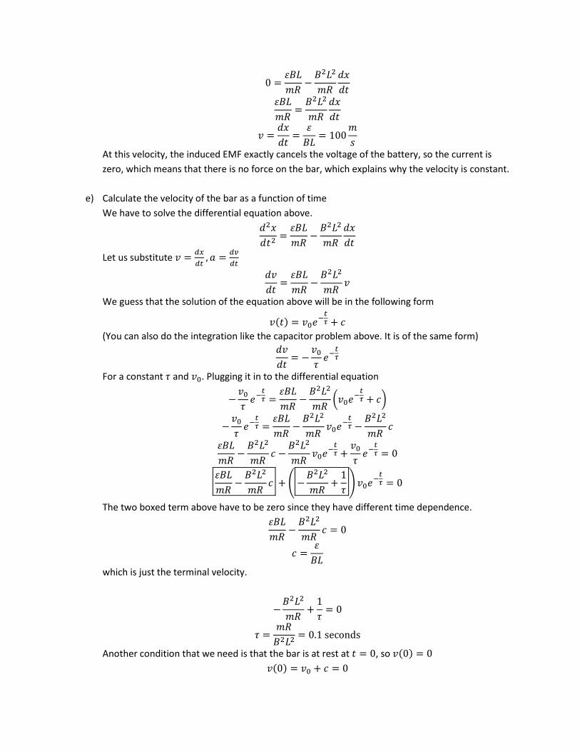
At this velocity, the induced EMF exactly cancels the voltage of the battery, so the current is
zero, which means that there is no force on the bar, which explains why the velocity is constant.
e) Calculate the velocity of the bar as a function of time
We have to solve the differential equation above.
Let us substitute
We guess that the solution of the equation above will be in the following form
( )
(You can also do the integration like the capacitor problem above. It is of the same form)
For a constant and . Plugging it in to the differential equation
(
)
(
)
The two boxed term above have to be zero since they have different time dependence.
which is just the terminal velocity.
Another condition that we need is that the bar is at rest at , so ( )
( )
( )
(
)
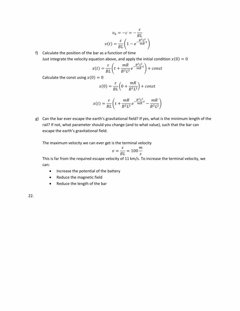
f) Calculate the position of the bar as a function of time
Just integrate the velocity equation above, and apply the initial condition ( )
( )
(
)
Calculate the const using ( )
( )
(
)
( )
(
)
g) Can the bar ever escape the earth’s gravitational field? If yes, what is the minimum length of the
rail? If not, what parameter should you change (and to what value), such that the bar can
escape the earth’s gravitational field.
The maximum velocity we can ever get is the terminal velocity
This is far from the required escape velocity of 11 km/s. To increase the terminal velocity, we
can:
Increase the potential of the battery
Reduce the magnetic field
Reduce the length of the bar
22.
Recommended