PHASE | VISLINK:
Antenas e Amplificadores
Antenas……………………………...p. 2
Barrel Booster.………….................p. 4
Link L3205 Transmitter Case..........p. 6
Gigawave designs and manufactures a wide range of antennas to suit
all microwave transmission requirements. The antennas are designed
to perform in all conditions, and are used everyday throughout the
world in a variety of broadcast and security applications.
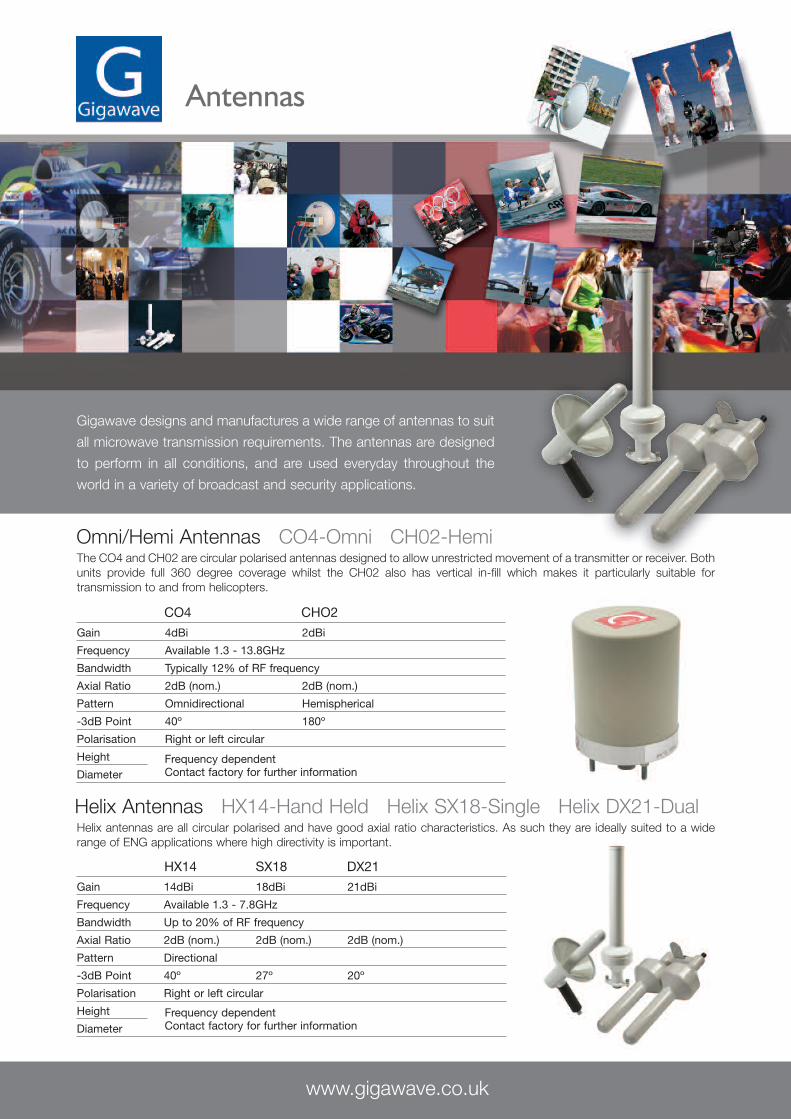
Omni/Hemi Antennas CO4-Omni CH02-HemiThe CO4 and CH02 are circular polarised antennas designed to allow unrestricted movement of a transmitter or receiver. Bothunits provide full 360 degree coverage whilst the CH02 also has vertical in-fill which makes it particularly suitable fortransmission to and from helicopters.
CO4 CHO2
Gain 4dBi 2dBi
Frequency Available 1.3 - 13.8GHz
Bandwidth Typically 12% of RF frequency
Axial Ratio 2dB (nom.) 2dB (nom.)
Pattern Omnidirectional Hemispherical
-3dB Point 40º 180º
Polarisation Right or left circular
Height
DiameterFrequency dependentContact factory for further information
HX14 SX18 DX21
Gain 14dBi 18dBi 21dBi
Frequency Available 1.3 - 7.8GHz
Bandwidth Up to 20% of RF frequency
Axial Ratio 2dB (nom.) 2dB (nom.) 2dB (nom.)
Pattern Directional
-3dB Point 40º 27º 20º
Polarisation Right or left circular
Height
DiameterFrequency dependentContact factory for further information
www.gigawave.co.uk
Helix Antennas HX14-Hand Held Helix SX18-Single Helix DX21-DualHelix antennas are all circular polarised and have good axial ratio characteristics. As such they are ideally suited to a widerange of ENG applications where high directivity is important.
Antennas
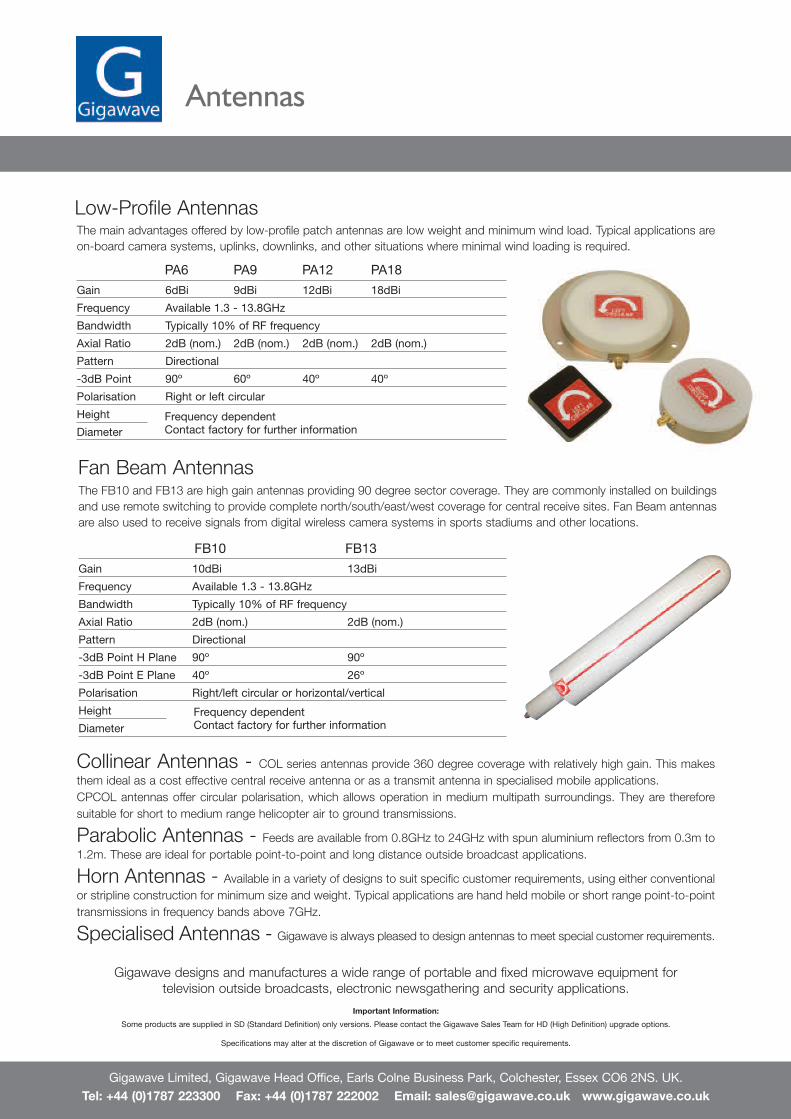
Fan Beam AntennasThe FB10 and FB13 are high gain antennas providing 90 degree sector coverage. They are commonly installed on buildingsand use remote switching to provide complete north/south/east/west coverage for central receive sites. Fan Beam antennasare also used to receive signals from digital wireless camera systems in sports stadiums and other locations.
FB10 FB13
Gain 10dBi 13dBi
Frequency Available 1.3 - 13.8GHz
Bandwidth Typically 10% of RF frequency
Axial Ratio 2dB (nom.) 2dB (nom.)
Pattern Directional
-3dB Point H Plane 90º 90º
-3dB Point E Plane 40º 26º
Polarisation Right/left circular or horizontal/vertical
Height
DiameterFrequency dependentContact factory for further information
Collinear Antennas - COL series antennas provide 360 degree coverage with relatively high gain. This makesthem ideal as a cost effective central receive antenna or as a transmit antenna in specialised mobile applications.CPCOL antennas offer circular polarisation, which allows operation in medium multipath surroundings. They are thereforesuitable for short to medium range helicopter air to ground transmissions.
Parabolic Antennas - Feeds are available from 0.8GHz to 24GHz with spun aluminium reflectors from 0.3m to1.2m. These are ideal for portable point-to-point and long distance outside broadcast applications.
Horn Antennas - Available in a variety of designs to suit specific customer requirements, using either conventionalor stripline construction for minimum size and weight. Typical applications are hand held mobile or short range point-to-pointtransmissions in frequency bands above 7GHz.
Specialised Antennas - Gigawave is always pleased to design antennas to meet special customer requirements.
PA6 PA9 PA12 PA18
Gain 6dBi 9dBi 12dBi 18dBi
Frequency Available 1.3 - 13.8GHz
Bandwidth Typically 10% of RF frequency
Axial Ratio 2dB (nom.) 2dB (nom.) 2dB (nom.) 2dB (nom.)
Pattern Directional
-3dB Point 90º 60º 40º 40º
Polarisation Right or left circular
Height
DiameterFrequency dependentContact factory for further information
Low-Profile AntennasThe main advantages offered by low-profile patch antennas are low weight and minimum wind load. Typical applications areon-board camera systems, uplinks, downlinks, and other situations where minimal wind loading is required.
Gigawave Limited, Gigawave Head Office, Earls Colne Business Park, Colchester, Essex CO6 2NS. UK.Tel: +44 (0)1787 223300 Fax: +44 (0)1787 222002 Email: [email protected] www.gigawave.co.uk
Gigawave designs and manufactures a wide range of portable and fixed microwave equipment fortelevision outside broadcasts, electronic newsgathering and security applications.
Important Information:
Some products are supplied in SD (Standard Definition) only versions. Please contact the Gigawave Sales Team for HD (High Definition) upgrade options.
Specifications may alter at the discretion of Gigawave or to meet customer specific requirements.
Antennas
PU
BL
IC
SA
FE
YVIS
LINK N
ews and Entertainm
ent
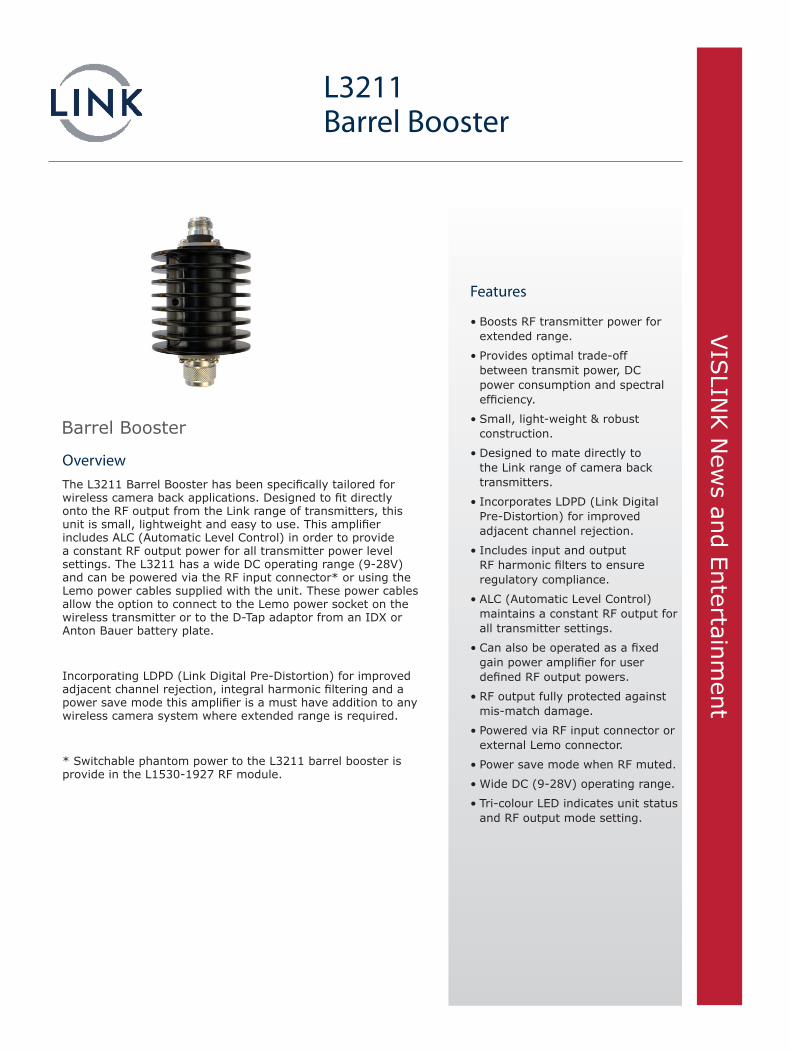
OverviewThe L3211 Barrel Booster has been specifically tailored for wireless camera back applications. Designed to fit directly onto the RF output from the Link range of transmitters, this unit is small, lightweight and easy to use. This amplifier includes ALC (Automatic Level Control) in order to provide a constant RF output power for all transmitter power level settings. The L3211 has a wide DC operating range (9-28V) and can be powered via the RF input connector* or using the Lemo power cables supplied with the unit. These power cables allow the option to connect to the Lemo power socket on the wireless transmitter or to the D-Tap adaptor from an IDX or Anton Bauer battery plate.
Incorporating LDPD (Link Digital Pre-Distortion) for improved adjacent channel rejection, integral harmonic filtering and a power save mode this amplifier is a must have addition to any wireless camera system where extended range is required.
* Switchable phantom power to the L3211 barrel booster is provide in the L1530-1927 RF module.
L3211Barrel Booster
Barrel Booster
Features
• Boosts RF transmitter power for extended range.
• Provides optimal trade-off between transmit power, DC power consumption and spectral efficiency.
• Small, light-weight & robust construction.
• Designed to mate directly to the Link range of camera back transmitters.
• Incorporates LDPD (Link Digital Pre-Distortion) for improved adjacent channel rejection.
• Includes input and output RF harmonic filters to ensure regulatory compliance.
• ALC (Automatic Level Control) maintains a constant RF output for all transmitter settings.
• Can also be operated as a fixed gain power amplifier for user defined RF output powers.
• RF output fully protected against mis-match damage.
• Powered via RF input connector or external Lemo connector.
• Power save mode when RF muted.
• Wide DC (9-28V) operating range.
• Tri-colour LED indicates unit status and RF output mode setting.
www.vislink.com© 2014 Vislink Group. All rights reserved. All other products or services referenced herein are identified by the trademarks or service marks of their respective companies or organizations. Note: Vislink reserves the right to change specifications without notice. Please contact your representative to confirm current specifications. Document 04 / 02 / 2014
SpecificationsElectrical At 20±5°C ambient
Parameter Conditions Min Typ Max Units Comment
Frequency Range L3211-2027 2000 – 2700 MHz
L3211-6475 6400 - 7500 MHz Does not include LDPD
RF Output Power ALC Mode +28 (0.63) 28.75(0.75) +30 (1.0) dBm (W)
RF Input Power Range ALC Mode +10 (10) – +24 (250) dBm (mW)
Gain Fixed Gain Mode 10 – 15 dB
Spectral Regrowth Adjacent Channel – – -40 dBc EN 302 064-1 §7.3.4
Alternate Channe – – -46
Spurious 25MHz – 1GHz – – 0.25(-36) nW(dBm) EN 302 064-1 §7.4.6
1GHz – 27GHz – – 1(-30)
Return Loss – 10 – dB
RF InputDamage Level
CW +27 (0.5) dBm (W)
Pulsed +36 (4)
Static Protection Direct Discharge 8 kV IEC61000-4-2
Air Discharge 15
Temperature Rise Above Ambient 32 ºC IEC60417-5041
Supply Voltage 9 28 V
Power Consumption RF OFF 7.5 W
RF ON 14 W
Compliance
Standard Class/Category Version
ETSI EN 302 064-1 Category 1 V1.1.2
ETSI EN 301 489-28 Class B V1.1.1
EnvironmentalOperating Temperature (Portable Equipment)• -10°C to +50°C
Storage Temperature• -20°C to +80°C
Humidity • 95%• Non-Condensing
IP Rating• 54
Mechanical RF/DC Input Connector• 50Ω N Type (M)
RF Output Connector• 50Ω N Type (F)
Power Connector• 6-Pin Lemo Socket
Phantom Power • Applied to RF Input Connector
Weight• 0.32Kg
Length• 106mm (inc. connectors)
Diameter• 62mm
Status Indicator• Green (DC Power/ALC OK)• Orange (DC Power OK/Fixed Gain)
Power Connector 6-Pin Lemo SocketL3211 Socket• EEG.OB.306 CLV
Mating Plug• FGG.0B.306 CLA (straight)• FHG.0B.306 CLA (right-angle)
Pin Out• 1 & 2: GND, 3 & 4: +VE, 5 & 6: NC
Note: When operating the barrel booster in the ‘Fixed Gain’ mode the RF output power is no longer controlled by the barrel booster’s ALC and therefore it is the operator’s responsibility to ensure that the RF drive into the barrel booster is at an appropriate level not to cause over-drive or damage and to maintain regulatory compliance.
Hot surface, do not touch barrel booster heat sink surface during operation.
Optional power cables are available as listed below
9003434 Barrel Booster ALC Power Cable (Lemo straight)
9003435 Barrel Booster ALC Power Cable (IDX D-TAP)
9003437 Barrel Booster ALC Power Cable (Anton Bauer P-TAP)
9003438 Barrel Booster ALC Power Cable (Lemo right-angle)
9007896 Barrel Booster ALC Power Cable (XLR 3pin)
9008305 Barrel Booster Power Cable (Fixed Gain Lemo)
9008304 Barrel Booster Power Cable (Fixed Gain IDX D Tap)
9011941 Barrel Booster Power Cable (75cm un-terminated)
PU
BL
IC
SA
FE
TY
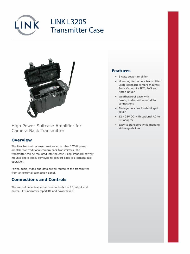
OverviewThe Link transmitter case provides a portable 5 Watt power amplifier for traditional camera back transmitters. The transmitter can be mounted into the case using standard battery mounts and is easily removed to convert back to a camera back operation.
Power, audio, video and data are all routed to the transmitter from an external connection panel.
Connections and Controls
The control panel inside the case controls the RF output and power. LED indicators report RF and power levels.
LINK L3205Transmitter Case
High Power Suitcase Amplifier for Camera Back Transmitter
Features• 5 watt power amplifier
• Mounting for camera transmitter using standard camera mounts: Sony V-mount / IDX, PAG and Anton Bauer
• Weatherproof case with power, audio, video and data connections
• Storage pouches inside hinged cover
• 12 - 28V DC with optional AC to DC adapter
• Easy to transport while meeting airline guidelines
www.vislink.com
© 2013 Vislink Group. All rights reserved. All other products or services referenced herein are identified by the trademarks or service marks of their respective companies or organizations. Note: Vislink reserves the right to change specifications without notice. Please contact your representative to confirm current specifications. 26 / 06 / 2013
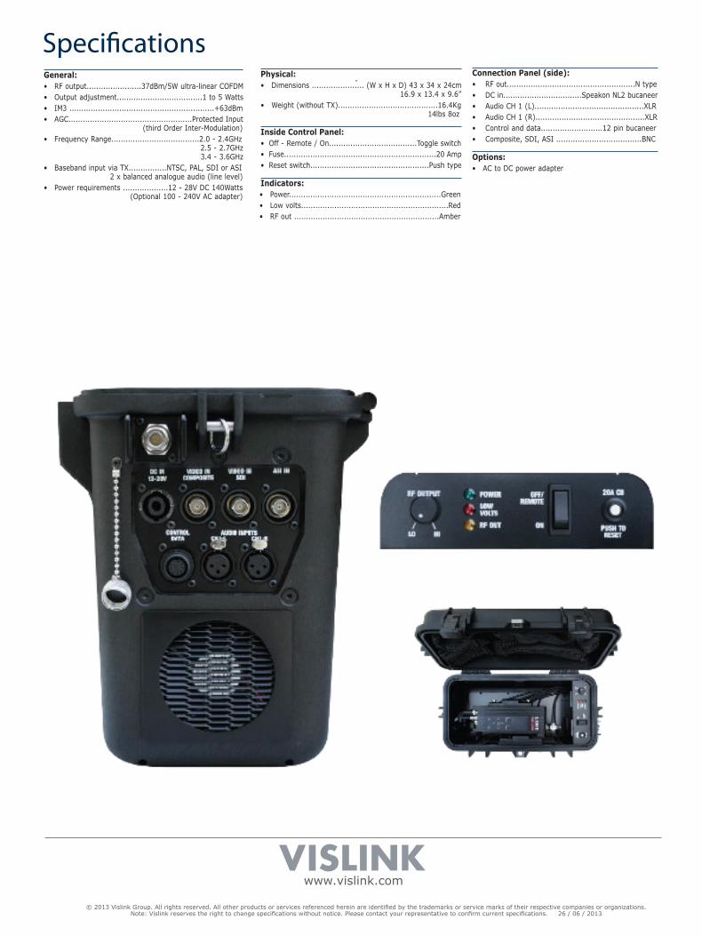
SpecificationsGeneral:• RF output.......................37dBm/5W ultra-linear COFDM• Output adjustment....................................1 to 5 Watts• IM3 .............................................................+63dBm• AGC....................................................Protected Input
(third Order Inter-Modulation)• Frequency Range.....................................2.0 - 2.4GHz
2.5 - 2.7GHz 3.4 - 3.6GHz
• Baseband input via TX................NTSC, PAL, SDI or ASI 2 x balanced analogue audio (line level)
• Power requirements ...................12 - 28V DC 140Watts (Optional 100 - 240V AC adapter)
Physical:• Dimensions ...................... (W x H x D) 43 x 34 x 24cm
16.9 x 13.4 x 9.6”• Weight (without TX)..........................................16.4Kg
14lbs 8oz
Inside Control Panel:• Off - Remote / On.....................................Toggle switch• Fuse................................................................20 Amp• Reset switch..................................................Push type
Indicators:• Power................................................................Green • Low volts..............................................................Red• RF out .............................................................Amber
Connection Panel (side):• RF out......................................................N type• DC in.................................Speakon NL2 bucaneer• Audio CH 1 (L)..............................................XLR• Audio CH 1 (R)..............................................XLR• Control and data..........................12 pin bucaneer• Composite, SDI, ASI ....................................BNC
Options:• AC to DC power adapter

PHASE ENGENHARIA
Wireless Camera Systems
EXCLUSIVE REPRESENTATIVE:

PHASE Engenharia Ind. e Com. Ltda.
Av. Olegário Maciel 231, Lojas 101 a 105
Barra da Tijuca | Rio de Janeiro, RJ | CEP 22 621 200
Tel +55.21.2493.0125
Av. Ibirapuera 2.907, Conj. B306 & 7 - Ed. Conv. Corp. Plaza – Torre C
Indianópolis | São Paulo-SP | CEP 04029-200
Tel +55 11 3589-0125
[email protected] | www.phase.com.br
Recommended