Faculty of Engineering
Master Degree in
Artificial Intelligence and Robotics
Person-tracking and gesture-driven
interaction with a mobile robot using the
Kinect sensor
Supervisor Candidate
Prof. Luca Iocchi Taigo Maria Bonanni
Academic Year 2010/2011
To this journey,
which reached the end.
To all those adventures
that have yet to come.
Contents
1 Introduction 1
1.1 Scope . . . . . . . . . . . . . . . . . . . . . . . . . . . . . . . 4
1.2 Contributions . . . . . . . . . . . . . . . . . . . . . . . . . . . 5
1.3 Thesis outline . . . . . . . . . . . . . . . . . . . . . . . . . . . 6
I Preliminaries 7
2 Background 8
2.1 Introduction . . . . . . . . . . . . . . . . . . . . . . . . . . . . 8
2.2 Human-Robot Interaction . . . . . . . . . . . . . . . . . . . . 8
2.2.1 Design Approaches . . . . . . . . . . . . . . . . . . . . 10
2.2.2 Human-oriented Perception . . . . . . . . . . . . . . . 12
2.3 Tracking . . . . . . . . . . . . . . . . . . . . . . . . . . . . . . 13
2.3.1 Object Representation . . . . . . . . . . . . . . . . . . 15
2.3.2 Feature Selection . . . . . . . . . . . . . . . . . . . . . 17
2.3.3 Object Detection . . . . . . . . . . . . . . . . . . . . . 18
2.3.4 Object Tracking . . . . . . . . . . . . . . . . . . . . . . 19
2.4 Gesture Recognition . . . . . . . . . . . . . . . . . . . . . . . 20
2.4.1 Hidden Markov Model . . . . . . . . . . . . . . . . . . 22
2.4.2 Finite State Machine . . . . . . . . . . . . . . . . . . . 24
2.4.3 Particle Filtering . . . . . . . . . . . . . . . . . . . . . 25
2.4.4 Soft Computing Approaches . . . . . . . . . . . . . . . 26
ii

CONTENTS
II Implementation 28
3 Design and System Architecture 29
3.1 Introduction . . . . . . . . . . . . . . . . . . . . . . . . . . . . 29
3.2 Hardware Components . . . . . . . . . . . . . . . . . . . . . . 32
3.2.1 Erratic Robot . . . . . . . . . . . . . . . . . . . . . . . 32
3.2.2 Kinect Sensor . . . . . . . . . . . . . . . . . . . . . . . 32
3.2.3 Pan-Tilt Unit . . . . . . . . . . . . . . . . . . . . . . . 35
3.3 Software Components . . . . . . . . . . . . . . . . . . . . . . . 38
3.3.1 Player . . . . . . . . . . . . . . . . . . . . . . . . . . . 38
3.3.2 OpenNI . . . . . . . . . . . . . . . . . . . . . . . . . . 41
3.3.3 NITE . . . . . . . . . . . . . . . . . . . . . . . . . . . 42
3.3.4 OpenCV . . . . . . . . . . . . . . . . . . . . . . . . . . 44
4 Person-Tracking 45
4.1 Introduction . . . . . . . . . . . . . . . . . . . . . . . . . . . . 45
4.2 CoM Tracking . . . . . . . . . . . . . . . . . . . . . . . . . . . 46
4.3 CoM Tracking with P Controller . . . . . . . . . . . . . . . . . 50
4.4 Blob Tracking . . . . . . . . . . . . . . . . . . . . . . . . . . . 51
5 Gesture-driven Interaction 60
5.1 Introduction . . . . . . . . . . . . . . . . . . . . . . . . . . . . 60
5.2 Recognizable Gestures . . . . . . . . . . . . . . . . . . . . . . 61
5.3 Interaction . . . . . . . . . . . . . . . . . . . . . . . . . . . . . 65
III Results 70
6 Experiments 71
6.1 Introduction . . . . . . . . . . . . . . . . . . . . . . . . . . . . 71
6.2 Person-Tracking Evaluation . . . . . . . . . . . . . . . . . . . 72
6.2.1 Experimental Design . . . . . . . . . . . . . . . . . . . 72
6.2.2 Results . . . . . . . . . . . . . . . . . . . . . . . . . . . 72
6.3 Gesture Recognition Evaluation . . . . . . . . . . . . . . . . . 73
6.3.1 Experimental Design . . . . . . . . . . . . . . . . . . . 73
iii
CONTENTS
6.3.2 Results . . . . . . . . . . . . . . . . . . . . . . . . . . . 74
6.4 Joint Evaluation . . . . . . . . . . . . . . . . . . . . . . . . . 74
6.4.1 Experimental Design . . . . . . . . . . . . . . . . . . . 75
6.4.2 Results . . . . . . . . . . . . . . . . . . . . . . . . . . . 75
7 Conclusions 78
Acknowledgements 81
Bibliography 81
iv

Chapter 1
Introduction
Further to the technological breakthroughs achieved by industry and robotic
research in the last years, robots are moving out from factories entering our
houses and lives. For several years, their use has been limited to production
lines, while nowadays, different robotic systems (e.g. manipulators, wheeled
or humanoid robots) can be seen performing the most disparate tasks: either
in critical scenarios as mine and bomb detection and disposal, search and
rescue, military applications, scientific explorations or uncritical domains as
health care, entertainment (e.g. robots that play football, or pretend to,
museum guides) and domestic services (e.g. dishwashers, vacuum cleaners).
The spread of these robotic systems and the frequent interaction with humans
in these scenarios led to the broadening of another subject area: human-robot
interaction, also known as HRI.
HRI is a multidisciplinary research field, which embraces concepts be-
longing to technical sciences as robotics, artificial intelligence and human-
computer interaction together with humanities as social sciences, psychology
and natural language processing. Human–robot interaction is dedicated to
understanding, designing, and evaluating robotic systems to use by or with
humans, with the aim of achieving a worldwide diffusion similar to the com-
puters revolution, which gave rise during the 1990s to the Information Age,
with the robots perceived as mass consumption products. Human-robot in-
teraction involves a continuous communication between humans and robots,
1

Introduction
where communications are implementable in different ways, depending on
whether the human and the robot are in close proximity to each other or
not. Thus, we can distinguish two general categories of interaction:
Remote interaction: humans and robots do not share the same physical
workspace, being separated spatially or even temporally (e.g. the Mars
Rovers are separated from the Earth both in space and time);
Proximate interaction: humans and robots are located within the same
workspace (for example, service robots may be in the same room as
humans).
In the latter, which is the interaction paradigm addressed in this work, ap-
plication scenarios require a closer interaction between humans and robots.
Such closeness has to be intended both literally, since the two entities share
the same workspace at the same time, and metaphorically, because they par-
take the same goals for the accomplishment of the task to be performed.
Following the explanation provided for the closeness concept, we can intro-
duce two different, but not completely disjoint, facets of interaction:
Safety : being potentially harmful for the humans, researchers aim to achieve
a safe physical interaction between robots and humans; to this end, sev-
eral aspects are involved, from the design of compliant parts, as flexible
links or joints, to the implementation of procedures, like obstacle avoid-
ance algorithms;
Friendliness : the research focuses towards a human-friendly interaction,
based communication means easy and intuitive for humans, as facial
expressions, speech and gestures.
Clearly, both levels of interaction imply a very important feature every robot
should exhibit (in order to be really considered a robot, not a simple ma-
chine): adaptability. For a safe interaction, robots should adapt themselves
to the environments they are in, since there can be static and dynamic enti-
ties (a robot may stand still, but it is unlikely a human will, unless he is tied);
for a social interaction, robots should adapt to our typical communication
2

Introduction
means, such as speaking or gesturing, as well as to our attitude; for example,
”understanding” when two expressions are actually dissimilar, or are just
performed in a slightly different way (one only needs to think about how
different is a gesture executed ten times in a row). From the robot perspec-
tive, what we introduce here is situation awareness, described by Endsley
(1995) as: ”the perception of elements in the environment within a volume
of time and space, the comprehension of their meaning, and the projection of
their status in the near future”; from the human perspective, this conscious-
ness, called human-robot awareness, has been defined by Drury et al. (2003)
as: ”the understanding that the humans have of the locations, identities, ac-
tivities, status and surroundings of the robots”. These definitions allow us
to introduce the most important concept for the evaluation of an effective
human-robot interaction: awareness, meaning a reciprocal comprehension of
the status of both the involved entities, humans and robots, their activities,
their tasks and the environment.
At this point, a question arises: how is this interaction achieved? From
the robot perspective, the interaction requires a complex set of components:
robots need perceiving and understanding capabilities to model dynamic en-
vironments, to distinguish between objects, to recognize humans and to inter-
pret their emotions, hence sensors to acquire data from the world, algorithms
and a high-level knowledge to interpret these data in meaningful ways.
From the human standpoint, usually a human-robot interface is required.
The literature offers a wide range of examples of interface, from common
graphical user interfaces, or GUI s, like mice or keyboards, to more sophis-
ticated tangible user interfaces, also called TUI s, like the Wii-Remote. Re-
gardless of the kind of device used, human-robot interfaces exhibit different
limitations, turning out to be the critical point of HRI applications. In the
first case, the interaction is based on the manipulation of the graphical el-
ements represented on a screen; while this constitutes a good solution for
human-computer interaction, GUIs result inadequate when interacting with
a robotic system for two distinct reasons. On the one side, because of the
greater complexity of both the robot, with a greater number of degrees of
freedom with respect to the manipulation degrees of common input devices,
3

Introduction 1.1 Scope
and the real world, far more complex than the virtual representation of an
environment. On the other side, because GUIs are interfaces designed for
desktop PCs that are inherently static, hence there is no mobility at all. In
the second case, the user can manipulate the digital information through the
physical environment, taking advantage of a more comfortable interaction
mean, also guaranteeing the mobility required.
With this thesis, we want to propose a novel approach for a socially inter-
active robot whose behaviour is driven by user’s gestures, with the intention
to move toward a new model of interaction between humans and robots,
more comfortable and natural for the formers, through a new robot inter-
face. It is worth noting that robotic platforms will be perceived as mass
consumption products only through the achievement of really simple inter-
action paradigms, suitable for everyone, from the expert to the novice. We
already introduced GUIs and TUIs, highlighting the higher suitability of tan-
gible interfaces with respect to graphical input devices, when interacting with
robots. Nevertheless, TUIs require a high amount of human effort and skills
to be properly used, proving to be efficiently usable only by specialists. If
this limitation sounds acceptable for critical scenarios like rescue robotics,
which is not appropriate for inexperienced operators, it is unreasonable for
uncritical scenarios, particularly when robots and humans are involved in
social forms of interaction. For this reason, with our platform, that will be
discussed in Chapter 3, we present a vision-based gesture-driven interaction
implementation for a socially interactive robot, where the only user interface
is installed on the robot, relieving the human from any device.
1.1 Scope
As mentioned before, human-robot interaction is a wide research field in
continuous expansion, applied to a broad range of different domains. In order
to make robotic systems accessible to a wider audience, there is the need
to address novel paradigms for a simpler interaction between humans and
robots, discarding wearable and graspable user interfaces, which in fact make
those platforms usable only for system experts, due to the effort required to
4
Introduction 1.2 Contributions
the user for an effective interaction. To narrow down the ambit of this thesis,
we introduce the following assumptions:
• we restrain the range of all the possible application fields, consider-
ing a social scenario, where the robot moves in an indoor structured
environment, interacting with humans;
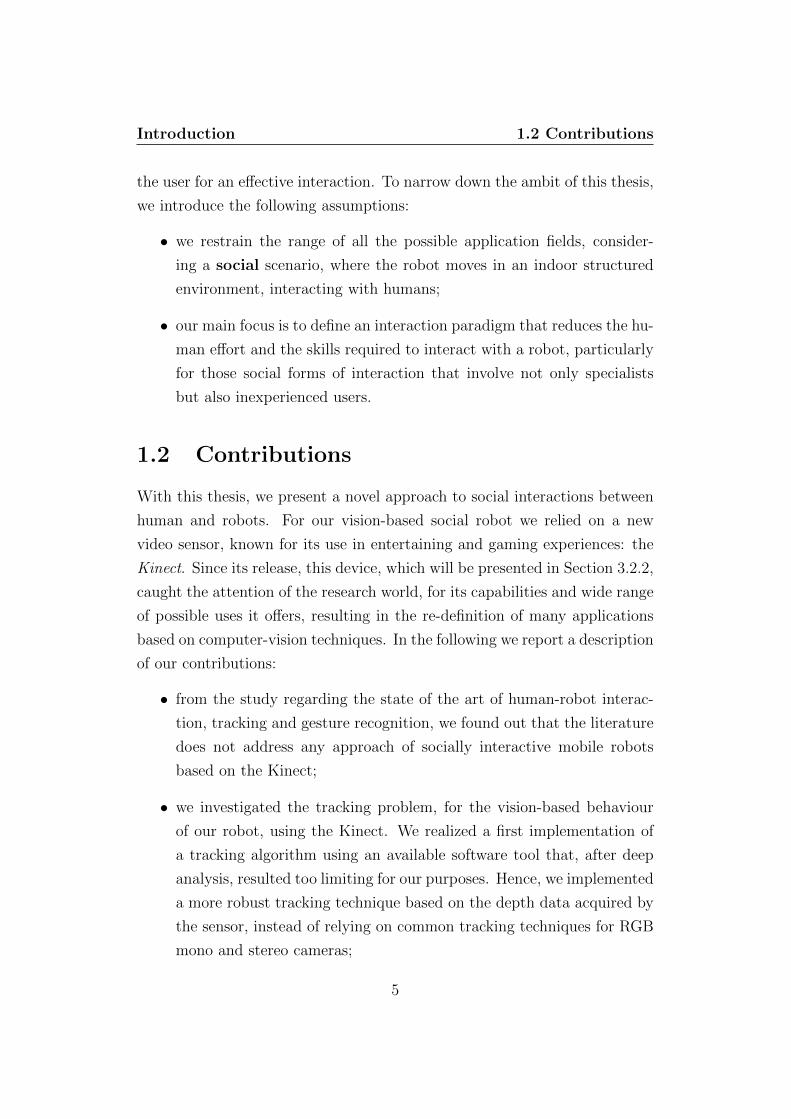
• our main focus is to define an interaction paradigm that reduces the hu-
man effort and the skills required to interact with a robot, particularly
for those social forms of interaction that involve not only specialists
but also inexperienced users.
1.2 Contributions
With this thesis, we present a novel approach to social interactions between
human and robots. For our vision-based social robot we relied on a new
video sensor, known for its use in entertaining and gaming experiences: the
Kinect. Since its release, this device, which will be presented in Section 3.2.2,
caught the attention of the research world, for its capabilities and wide range
of possible uses it offers, resulting in the re-definition of many applications
based on computer-vision techniques. In the following we report a description
of our contributions:
• from the study regarding the state of the art of human-robot interac-
tion, tracking and gesture recognition, we found out that the literature
does not address any approach of socially interactive mobile robots
based on the Kinect;
• we investigated the tracking problem, for the vision-based behaviour
of our robot, using the Kinect. We realized a first implementation of
a tracking algorithm using an available software tool that, after deep
analysis, resulted too limiting for our purposes. Hence, we implemented
a more robust tracking technique based on the depth data acquired by
the sensor, instead of relying on common tracking techniques for RGB
mono and stereo cameras;
5

Introduction 1.3 Thesis outline
• we investigated the gesture recognition problem, analysing the issues
arising from the use of the Kinect. Through gesture classifiers we im-
plemented a gesture-driven interaction subsystem to control the robot,
evaluating the success rate of the recognition system as well as the
simplicity of use under static conditions;
• we integrated tracking and gesture recognition onto a mobile robotic
platform for a person-following task, hence evaluating the whole system
under dynamic mobility conditions (which are for sure more compelling
than static ones), when both the robot and the human move in an
environment.
1.3 Thesis outline
This thesis is divided into six chapters. In Chapter 2 we address our research
problem, also introducing several theoretical notions, and provide a state
of the art of the relevant topics analysed in this work. Chapter 3 describes
the system architecture we assembled for our human-friendly robot, detailing
the different hardware and software components it consists of. In Chapter 4
and Chapter 5 we detail our contributions for the topics addressed in this
work. Chapter 6 provides an overview of both the experimental setup and
the results of the tests we executed to evaluate the robustness and the actual
simplicity of our platform. Finally, in Chapter 7 we report the conclusions
of this thesis, also addressing possible future works.
6

Part I
Preliminaries
7

Chapter 2
Background
2.1 Introduction
In this chapter, we provide a theoretical background of the relevant topics
covered by this thesis, in order to well define the scope of our work, together
with the most relevant work in the state of the art.
In Section 2.2, we deeply investigate the research field of this thesis,
namely, human-robot interaction. Section 2.3 presents the problem of Track-
ing a target, or multiple targets. Finally, in Section 2.4, we discuss the
Gesture Recognition problem.
2.2 Human-Robot Interaction
In Chapter 1 we provided a brief introduction of human-robot interaction,
presenting two general classifications, remote and proximate interaction, and
detailing the latter, while in this chapter we detail the social aspect within
HRI.
Social interaction includes social, emotive, and cognitive facets of interac-
tion, where humans and robots interact as peers or companions, sharing the
same workspace and the same goals. Dautenhahn and Billard (1999) pro-
pose the following definition to describe the concept of social robot: Social
robots are embodied agents that are part of a heterogeneous group: a society
8
Background 2.2 Human-Robot Interaction
of robots or humans. They are able to recognize each other and engage in
social interactions, they possess histories (perceive and interpret the world
in terms of their own experience), and they explicitly communicate with and
learn from each other. According to Fong et al. (2003), the development
of such robots requires the use of different techniques to deal with the fol-
lowing aspects: awareness of its interaction counterpart, social learning and
imitation, natural language and gesture based interaction. Furthermore, it
is worth remembering that HRI research aims to determine friendly social
behaviours, thus designing social robots as assistants, peers or companions
for humans.
Breazeal (2003) distinguishes social robots between four different classes,
in terms of how well the robot can support the social model it is involved in
and the complexity of the interaction scenario that can be supported.
Socially evocative: these robots are designed to leverage the human tendency
to anthropomorphize and are meant to evoke feelings in users;
Social interface robots provides a natural interface by employing human-
like social cues and communication means. Since these robots do not
possess any deep cognition model, the social behaviour is defined only
at the interface-level;
Socially receptive: these robots are passive social actors, but can benefit
from interaction (e.g. learning by imitation). Socially receptive robots
require a deeper model of human social competencies;
Sociable: pro-active social robots, they possess social goals, drives and emo-
tions. Usually these robotics systems incorporate deep models of social
cognition.
When speaking of socially interactive robots, we describe those robots for
which achieving social interaction is the key point, distinguishing them from
other classes of robots, that are involved different scenarios, such as teleop-
erated interaction. The importance of designing socially interactive robots
depends on the fact that humans prefer to interact with robots through
9

Background 2.2 Human-Robot Interaction
the same communication means they use for interacting with other humans.
On the human side, an effective degree of social human-robot interaction
is achieved only if the human feels comfortable when interacting with the
robot, highlighting the need for natural communication means. On the ma-
chine side, since they operate as humans’ peers or assistants, robots need to
exhibit adaptability to achieve an effective interaction, being capable of deal-
ing with different genders and ages, social and cultural backgrounds, without
lowering their performance.
In the following section, we present different design approaches for socially
interactive robots.
2.2.1 Design Approaches
From the design perspective, we can distinguish two ways of defining socially
interactive robots. Concerning the first approach, biologically inspired, robots
are designed to internally simulate, or mimic, the social structure inspired
by observing biological systems. With the second approach, functionally de-
signed, robots are built only to be externally perceived as socially intelligent,
without being internally designed as the previous platforms.
Biologically Inspired
This approach provides designs based on theories inspired by natural and
social sciences. The inspiration from biological systems is justified by two
motivations: on the one hand, nature is considered the best model for life-
like activity, hence, in order for a robot to be understandable by humans, it
must possess a realistic embodiment, it has to interact with the environment
as living creatures do and perceive things that are relevant for humans. On
the other hand, this design allows to fully understand, test and refine the
theories the design is based on.
Ethology : based on observational study of animals in their natural setting, it
describes the features a robot has to exhibit in order to appear creature-
like, if not human-like (Arkin et al., 2003). Ethology is also useful to
10
Background 2.2 Human-Robot Interaction
understand different behavioural aspects like instinct, motivation and
concurrency.
Structure of interaction: the analysis of structures of interaction can help
the design of perceptive and cognitive systems through the identifica-
tion of key interaction patterns (Werry et al., 2001), which can be used
to implement interaction-aware robots.
Theory of mind : refers to those social skills that allow humans to correctly
attribute beliefs, goals, perceptions, feelings, and desires to themselves
and others.
Developmental psychology : an effective mechanism for creating robots en-
gaged in natural social exchanges. For example, the design of Kismet’s
synthetic nervous system, in particular the perception and behaviour
facets, is heavily inspired by the social development of human infants
(Breazeal, 2002).
Functionally Designed
According to this approach, the design of socially interactive robots is sim-
ply driven by the description of the mechanisms through which people, in
everyday life, understand socially intelligent creatures. In contrast to the
previous approach, functionally designed robots generally have constrained
operational and performance objectives. Consequently, these robots are re-
quired only to generate certain effects with respect to user’s inputs. A moti-
vations for functional design can be one of the following:
• The robot need to be only superficially socially competent, in partic-
ular when robotics systems are required short-term or limited-quality
interaction.
• The robot may present limited embodiment, few capabilities for inter-
action or may be constrained by the environment.
The most used approaches in functional design are introduced as follows:
11
Background 2.2 Human-Robot Interaction
• Human–computer interaction design: robots are designed using HCI
techniques, like heuristic evaluation, cognitive modeling, contextual in-
quiry and user testing.
• Iterative design: revising a design through evaluations. It is often
used to assess and overcome design failures or to improve the system,
according to information from analysis or use. Willeke et al. (2001),
for example, describe the evolution of a series of museum robots, each
of which designed as improvement of the previous generations.
2.2.2 Human-oriented Perception
For a meaningful interaction with humans, socially interactive robots are
required to perceive the world as humans do. This implies that social robots,
in addition to standard capabilities like obstacle avoidance, navigation and
localization, must exhibit perceptual abilities similar to humans. Clearly,
these perceptions have to be human-oriented, optimized for interacting with
humans and on a human level. Robots are designed, and equipped of sensors,
to track human features, such as body, face or hands, to interpret natural
language and to recognize facial expressions, gestures and user’s motion.
People Tracking
Tracking, detailed in Section 2.3, is the problem of detecting a target in the
image plane and following its motion over time. It represents, despite its
intrinsic difficulties and limitations, the best approach to make robots aware
of human presence, in HRI applications.
Speech Recognition
Speech recognition allows to simply interact with robots, resembling to the
interaction paradigms used between humans. Depending on the scenario,
speech recognition may be used to perform speaker tracking, turn-taking
dialogues, emotion analysis of the speaker, or executing actions according to
spoken commands.
12

Background 2.3 Tracking
Gesture Recognition
Gesturing, addressed in Section 2.4, is a communication mean used for both
adding further informations to speech and providing orders, locations or di-
rections. Although there are many ways to recognize gestures, vision-based
recognition has several advantages over other methods.
2.3 Tracking
Tracking, also referred to as object tracking or video tracking, is an extremely
significant subject in the computer-vision research field: in its basic version,
tracking can be thought of as the problem of identifying a target (or multiple
targets), situated in an image plane, and following its motion, performed in a
three dimensional scene. The spreading of powerful computers, alongside the
attainability of high-quality stereo or mono cameras reasonably-priced, facil-
itated the development of more complex applications, leading to a growing
interest towards this topic.
A tracking algorithm consists of three key phases, despite the number of
targets to track: first, detection of interesting moving objects; second, track-
ing of such objects over time, or more specifically frame by frame, and finally
the analysis of the target to recognize its behaviour. As well as HRI, object
tracking is a continuously expanding topic, constituting the main component
for applications in different scenarios, such as:
Human-robot, human-computer interaction: gesture recognition, body mo-
tion detection, tracking of the eye gaze to modify the behaviour of the
machine, to navigate virtual environments or to manipulate data;
Security and surveillance: analysis of the scene to detect anomalous activi-
ties, or security control in critical domains;
Traffic monitoring : real-time analysis of the traffic in streets, harbours or
airports to coordinate and optimize the flows;
13
Background 2.3 Tracking
Vision-based navigation: motion-based detection of static and dynamic ob-
jects for the implementation of algorithms for on-line path planning
and obstacle avoidance.
Target tracking is a non-trivial task for very different motivations, which
range from technical to environmental reasons. Tracking algorithms are gen-
erally required to handle several difficulties, like the following:
• even the most accurate sensor suffers from noise, that introduces an
error in the two dimensional representation of the environment; more-
over, the projection of the three dimensional scene on a two dimensional
frame implies a loss of information;
• tracking vision-based algorithms suffer from changes in the light con-
ditions, especially those using histogram-based representations of the
target;
• partial or full occlusions of the target are difficult to handle, especially
if the obstacle is in proximity with the target;
• real-time requirements of the tracking task and processing power limi-
tations represent a bottleneck for a tracking algorithm;
• number of targets to be tracked simultaneously, their nature (rigid or
non-rigid), shape complexity and type of motion.
A common practice adopted when designing tracking algorithms is to con-
strain the problem, in order to narrow down the complexity of the implemen-
tation; for example, many tracking algorithms assume smooth motions for
the target, excluding abrupt changes, or require the target movements to be
of constant velocity or constant acceleration. These are just few examples of
constraints, other simplifying assumptions can be done, for example knowing
a priori the number of objects in the environment, their size and shape, or
how they appear. The literature is full of algorithms for the tracking prob-
lem; the main difference between them is how the problem is approached.
According to Yilmaz et al. (2006), every tracking algorithm provides an-
swers to the following questions: Which object representation is suitable for
14

Background 2.3 Tracking
tracking? Which image features should be used? How should the motion, ap-
pearance and shape of the object be modeled? Clearly, the answers are related
to the scenario in which the tracking is performed and the informations the
tracking algorithm has to return.
In the following sections, we investigate all the steps to implement a track-
ing algorithm (see Figure 2.1), presenting at the same time several related
works.
Object
Representation
Feature
Selection
Object
Detection
Object
Tracking
Figure 2.1: Illustration of the main steps of an object-tracking algorithm
2.3.1 Object Representation
Here we present a set of possible answers to the first question proposed:
Which object representation is suitable for tracking? Since a target can be
defined in many different ways, one should choose the best representation
according to the analysis to perform afterwards. In the following we present
several representations commonly used.
Point : the target is described by a point called centroid, fig.2.2(a), or by a
set of meaningful points, fig.2.2(b);
15

Background 2.3 Tracking
Simple Geometric Model : the target is approximated usign a rectangular,
fig.2.2(c), or an elliptical shape, fig.2.2(d);
Complex Geometric Model : complex targets are represented using simple
models, as before, connected by joints, fig.2.2(e);
Contour and Silhouette: the target is represented either by its boundaries
(contour), described using points,fig.2.2(g), or lines, fig.2.2(h), or by
the region inside the boundaries (silhouette), fig.2.2(i);
Skeleton Model : once extracted the silhouette associated to the target, the
skeleton model can be obtained applying medial axes to it, fig.2.2(f).
Figure 2.2: Different target representations. (a) Centroid, (b) Set of points,(c) Rectangular model, (d) Elliptical model, (e) Complex model, (f) Skeleton,(g) Points-based contour, (h) Complete contour, (i) Silhouette. [Courtesy ofAlper Yilmaz]
16
Background 2.3 Tracking
2.3.2 Feature Selection
After having introduced various feasible solutions for the target representa-
tion, now we describe a set of possible answer to the second question: Which
image features should be used? The choice of the feature which describes the
target is the key point in the implementation of a tracker: on the one side,
one should choose the feature with respect to the target representation used,
on the other hand, the feature should be chosen for its uniqueness, to easily
detect the target in the feature space. As for the target representation, in
the following we propose some well known solutions:
Color : it provides relevant informations for the recognition of the target,
usually coupled with a histogram-based representation. There are dif-
ferent color spaces, as: RGB, HSV and HSL. The choice of which one
to use is related to its robustness against changes in both illumination
and surface orientation of the target (especially for geometric complex
shapes);
Texture: it describes the target properties, as regularity and smoothness,
measuring the intensity variations of a surface. The target is fractioned
into a mosaic of different texture regions, which can be used for infor-
mation search and retrieval. Compared to the color features, textures
are less sensitive to changes in light conditions;
Edges : target boundaries generate strong changes in the intensity of an im-
age: these changes are identified through edge detection. As textures,
edges result less sensitive to illumination changes with respect to color
features. This also represents a good feature selection when tracking
the boundaries of the target;
Optical Flow : it provides a dense set of motion vectors defining the trans-
lation of the pixels in a region; for each pixel in a frame, optical flow
associates a vector pointing towards the position of the same pixel in
the next frame. This association is performed using a constraint on the
brightness, assuming constancy of corresponding pixels in consecutive
17
Background 2.3 Tracking
frames. This feature is commonly used for motion-based segmentation
and tracking applications.
2.3.3 Object Detection
At this point, a tracking algorithm requires a method to detect the target.
To this end, we can distinguish two approaches: either the detection is based
on the information one can extract from a single frame or one may rely on
temporal information, obtained analysing sequences of frames; the second
case is a little more complex but it is more robust and reliable than the first
one, reducing the chances of false detections. The simplest form for the ex-
traction of sequences of information is to compare two consecutive frames,
highlighting all the regions resulting different (this procedure is called frame
differencing); then, the tracker (see Section 2.3.4), matches the correspon-
dences of the target from one frame to the following one.
Point Detectors : used to find interest points in the frames, like the corners
of the objects, showing a meaningful texture. These points of interest
should be invariant with respect to both the pose of the camera and
light condition changes. Two examples of point detectors are Harris
Corner Detection algorithm, (Harris and Stephens, 1988), an improve-
ment of Moravec’s interest operator presented described in Moravec
(1979), and SIFT detector (Lowe, 2004);
Supervised Learning : the system learns to detect the target using training
sets, composed of different views of the same object. Given this set,
supervised-learning algorithms compute a matching function, mapping
the input to the desired output. In the object detection scenario, train-
ing samples consist of pairs of object features associated to an object
class, manually defined. Feature selection is very critical for achieving
a good classification, hence the choice should be done in such a way
that features discriminate a class from the others;
Background Subtraction: the detection is performed by building a represen-
tation of the scene, called background model and then, for each image,
18

Background 2.3 Tracking
looking for differences from that model: relevant changes, not small
changes which may depend on the noise, identify a moving object.
Then, the modified regions are clustered, if possible, in connected com-
ponents which correspond to the target. Frame differencing can be
performed in several ways, for example using color-based or spatial-
based informations of the scene;
Segmentation: in this approach, the frame is segmented into regions which
are perceived as similar. The goal is to simplify how the image is
represented, in a fashion way which is easier to analyse. Once the pixels
are clustered in regions, target can be located by searching particular
features, as color intensities, textures or edges.
2.3.4 Object Tracking
This represents the last step for the implementation of a tracking algorithm;
the goal of a tracker is to locate in every frame the position of the target.
In this section, we finally provide the answer to the last question proposed:
How should the motion, appearance and shape of the object be modeled? This
last step can be performed in two different ways: in the first case, for each
frame, the detection phase returns possible target regions and the tracker
matches the target in the image; in the second case, target regions and their
correspondences are directly estimated, updating the location of the previous
frame. In both cases, the model representing the target restrains the type of
motions that can be applied to it. For example, if the target is described using
a point, then only a translational motion could be considered, while more
complex representations for the target lead to a more accurate description
for its motion.
Point Tracking : the target detected in consecutive frames is described us-
ing significant points; the association of these points with the target is
based on the state of the previous frame, which can include target po-
sition and motion. This approach requires an external object detector
to locate the targets in every frame;
19
Background 2.4 Gesture Recognition
Kernel Tracking : the target is represented through a rectangular or an
elliptical model, also called kernel. Objects are tracked by computing
the motion of the kernel in consecutive frames;
Silhouette Tracking : this can be considered as a particular form of ob-
ject segmentation, because, once computed the model, the silhouette is
tracked by either shape matching or contour evolution. A silhouette-
based target tracker looks for the object region in each frame, using a
model generated according to the previous frames, through color his-
togram, object edges or the object contour.
2.4 Gesture Recognition
Gesture recognition is a relevant topic in both language technology and com-
puter science, whose aim is to comprehend human gestures through different
possible approaches, presented further on. We define a gesture, (Mitra and
Acharya, 2007), as a meaningful motion physically executed by, as example:
face, head, hands, arms or body. The importance of defining systems capa-
ble of understanding gestures, performed by one or more users, is related to
what they represent for us: an innate and simple communication mean, by
which we can easily express significant information and interact with the en-
vironment; hence, gesture recognition is needed to process this information,
not conveyed through more common means as speaking.
Gesture recognition is the milestone of a full variety of applications,
(Lisetti and Schiano, 2000), for example in the following fields:
Sign language recognition: design of techniques for translating the symbols
expressed by sign language into text (analogous to speech recognition
tools for computers);
Virtual and Remote control : gestures represent an alternative mean for
systems’ control, for example to select content on a television or to
manipulate a virtual environment;
20
Background 2.4 Gesture Recognition
Video games : players’ gestures are used within video games, instead of key-
boards and other devices, to offer a more entertaining and interactive
experience;
Patient rehabilitation: robots assist patients, for example for posture reha-
bilitation, analysing the readings of sensors installed on particular suits
the patients wear;
Human-robot and Human-computer interaction: in the former, gestures are
used to command a robot, more generally to influence its behaviour, or
to interact with it as a peer; in the latter, gestures substitute common
input devices as keyboard and mouse.
The main issue to face in gesture recognition is the intrinsic ambiguity of
the gestures humans perform, which may depend on different languages or
cultures or on the particular domain of application. For example, we can
enumerate at least three different ways to perform a ”stop” gesture: closing
the hand in a fist, waving both hands over the head or raising a hand with the
palm facing forward. Furthermore, similar to handwriting and speech, ges-
tures are usually performed differently between individuals and even by the
same individual between different instances. Moreover, gestures can be static,
in this case we define the problem as posture recognition, or dynamic, con-
sisting of three phases called respectively pre-stroke, stroke and post-stroke.
In some domains, as sign language recognition, gesture can be made of both
static and dynamic elements.
Gestures can be classified into three main different categories, clearly
related to the field of application:
• Hand and arm gestures : recognition of hand poses and sign languages;
• Head and face gestures : recognition of head-related motions, such as:
a) nodding or shaking of head; b) direction of eye gaze; c) raising the
eyebrows; d) opening the mouth to speak; e) winking; f) flaring the
nostrils; g) expression of emotions;
21

Background 2.4 Gesture Recognition
• Body gestures : estimation of full body motion, as in: a) tracking move-
ments of people interacting; b) navigation of virtual environments; c)
body-pose analysis for medical rehabilitation and athletic training.
Obviously, gesture recognition needs a sensing subsystem for perceiving body
position and orientation, configuration and movements, in order to accom-
plish its goal. These perceptions are usually acquired either through gestural
interfaces or using video sensors. Despite how the acquisition of meaningful
data is performed, gesture recognition can be implemented through several
equivalent techniques, presented in the following sections.
2.4.1 Hidden Markov Model
The HMM is a statistical process in which the system modeled is a Markov
process with hidden states. The main difference between a regular Markov
model and a hidden Markov model depends on the observability: in the for-
mer the state is visible to the observer, and therefore the state transition
probabilities are the only parameters. In the latter only the output, depen-
dent on the state, is visible, and each state is characterized by a probability
distribution over the possible output tokens. Transitions between states are
represented by a pair of probabilities, defined as follows:
1. Transition probability, providing the probability for undergoing the
transition;
2. Output probability, defining, given a state, the conditional probability
of outputting symbol from a finite alphabet.
A generic HMM λ = (A,B,Π), shown in Figure 2.3, is described as follows:
• a set of observation O = O1, ..., OT , where t = 1, . . . , T ;
• a set of N states s1, ..., sN ;
• a set of k discrete observation symbols v1, ..., vk;
22

Background 2.4 Gesture Recognition
• a state-transition matrix A = aij, where aij is the transition probability
from state si at time t to state sj at time t+ 1:
A = aij = P (sj at t+ 1|sj at t), for 1 ≤ i, j ≤ N
• an observation symbol probability matrix B = bjk, where bjk is the
probability of generating symbol vk from state sj;
• an initial probability distribution for the states:
Π = πj, j = 1, 2, . . . , N, where πj = P (sj at t = 1)
Figure 2.3: HMM for gesture recognition composed of five states
Each HMM is built up to recognize a single gesture, involving elegant and
efficient algorithms to perform the following steps:
1. Evaluation: determines the probability that the observed sequence is
generated by the HMM, using Forward-Backward algorithm;
2. Training : adjusts the parameters to refine the model, using Baum-
Welch algorithm;
3. Decoding : recovers the sequence of the states, using Viterbi algorithm.
A global gesture recognition system consists of a set of HMMs (λ1, λ2, . . . , λM),
where λi is the HMM model for a generic gesture and M is the total number
23
Background 2.4 Gesture Recognition
of gestures being recognized. Yamato et al. (1992) is the first work addressing
the problem of hand gesture recognition, using a discrete HMM to recognize
six classes of tennis strokes. Starner and Pentland (1995) and Weaver et al.
(1998) is presented a HMM-based, real-time system to recognize sentence-
level American sign language, without using an explicit model of the fingers.
2.4.2 Finite State Machine
Gestures are modeled through FSMs as ordered state sequences in a spatio-
temporal configuration space. The number of states composing the FSM is
variable among the different recognizers, depending on the complexity of the
gestures performed by the users. Gestures, represented through set of points
(e.g. sampled positions of the hand, head or body) in a 2D plane, are rec-
ognized as a trajectory from a continuous stream of sensor data constituting
an ensemble of trajectories. The training of the model is performed off-line,
using data sets as rich as possible in order to derive and refine the parameters
for each state in the FSM. Once trained, the finite state machine can be used
as well for real-time gesture recognition. When the user performs a gesture,
the recognizer decides whether to remain at the current state of the FSM
or jump to the next state, with respect to the parameters of the input; if
the recognition system reaches the final state of the FSM, then the gesture
performed by the user has been recognized. The state-based representation
can be extended to accommodate multiple models for the representation of
different gestures, or even different phases of the same gesture. Member-
ship in a state is determined by how well the state models can represent the
current observation.
Davis and Shah (1994) presented a FSM model-based approach to recog-
nize hand gestures, modeling four distinct phases of a generic gesture switch-
ing between static positions and motion of hand and fingers. Gesture recogni-
tion is based on hand vector displacement between the input and the reference
gestures. Hong et al. (2000) presented another FSM-based approach for ges-
ture learning and recognition: each gesture is described by an ordered state
sequence, using spatial clustering and temporal alignment. In the first place,
24
Background 2.4 Gesture Recognition
state-machines are trained using a training set of images for each gesture,
then the system is used to recognize gestures from an unknown input image
sequence. In Yeasin and Chaudhuri (2000), a user performs gestures in front
of a camera. The gesture is executed from any arbitrary spatio–temporal
configuration and its trajectory is continuously captured by the sensor; then,
acquired data are temporally segmented into subsequences characterized by
uniform dynamics along single directions, so that meaningful gestures may
be defined as sequences of elementary directions. For example, a simple
sequence right-left-right-left can represent a waving gesture.
2.4.3 Particle Filtering
Particle filters are sophisticated model estimation techniques based on simu-
lation, usually used to estimate Bayesian models where the latent, or hidden,
variables are connected in a Markov chain, but typically where the state space
of the latent variables is continuous rather than discrete. Filtering refers to
determining the distribution of hidden variables at a given (e meglio specific
di given?) time, considering all the observations up to that time; particle
filters are so named because they allow for approximate ”filtering” using a
set of ”particles” (differently-weighted samples of the distribution). Repre-
senting an alternative to the Extended Kalman filter (EKF) or Unscented
Kalman filter (UKF), particle filters offer better performance than the pre-
vious approaches in terms of accuracy, given a sufficient number of samples.
The key idea for estimating the state of dynamic systems from sensors’ read-
ings, is to represent probability densities by set of samples. As a result,
particle filters exhibit the ability to represent a wide range of probability
densities, allowing real-time estimation of non-linear, non-Gaussian dynamic
systems (Arulapalam et al., 2001). The state of a tracked object at time t is
described by a vector Xt, where the vector Yt represents all the samples of ob-
servations y1, y2, . . . , yt. The probability density distribution is approximated
by a weighted sample set St = 〈x(i)t, w(i)t〉|i = 1, . . . , Np. Here, each sample
x(i)t represents a hypothetical state of the target, and w(i)t represents the
25

Background 2.4 Gesture Recognition
corresponding discrete sampling probability of the sample x(i)t, such that:
Np∑i=1
w(i)t = 1
The evolution of the sample set is iteratively described propagating each
sample, according to a model. Each sample is weighted in terms of the
observations, and Np samples are drawn with replacement by choosing a
particular sample with posterior probability w(i)t = P (yt|Xt = x(i)t). In
each step of iteration, the mean state of an object is estimated as:
E(St) =
Np∑i=1
w(i)t x
(i)t
Since particle filters model uncertainty using posterior probability density,
this approach provides a robust tracking framework suitable for gesture recog-
nition systems. For example, Black and Jepson (1998) presented a mixed-
state condensation algorithm, based on particle filtering, to recognize a huge
number of different gestures analysing their temporal trajectories.
2.4.4 Soft Computing Approaches
Soft computing is a set of techniques for providing adaptable information-
processing capability, to handle real-life ambiguous situations. It is aimed
to exploit the tolerance for imprecision, uncertainty, approximate reason-
ing, and partial truth in order to achieve tractability, robustness, and low-
cost solutions. Sensor outputs are often associated with an inherent uncer-
tainty. Relevant, sensor-independent, invariant features are extracted from
these outputs, followed by gesture classification. Recognition systems may
be designed to be fully trained when in use, or may adapt dynamically to
the current user. Soft computing tools, such as fuzzy sets, artificial neural
networks (ANNs), time-delay neural networks (TDNNs) and others, exhibit
overall good performance for effectively handling these issues. In particular,
the flexible nature of ANNs enable connectionist approaches to incorporate
26

Background 2.4 Gesture Recognition
learning in data-rich environment. This characteristic, coupled with the ro-
bustness of this approach, is useful to develop recognition systems.
Yang and Ahuja (1998) is an example of TDNN-based approach for hand
gesture recognition of American sign language. Rowley and Kanade (1998)
and Tian et al. (2001) are two multy-layers-perceptron-based approaches re-
spectively for facial expression analysis and face detection, used in face ges-
ture recognition.
27

Part II
Implementation
28
Chapter 3
Design and System
Architecture
3.1 Introduction
In Chapter 1 we described the motivations of this work: the definition of a
new kind of social robot, based on a novel human-robot interaction paradigm,
which reduces the human effort required, both in terms of knowledge and
skills the user has to exhibit, that is to be accessible and easy to use for
everyone, not only for system experts. To us, the best approach to achieve
this goal is to rely on a communication mean natural for everyone: gesturing.
Clearly, the key point is to find an approach as simple as possible for the ges-
ture recognition problem, in order to guarantee the simplicity we are looking
for; hence, with our solution we provide the implementation of a simple yet
robust vision-based, gesture-driven interaction, which does not require any
graspable interface, allowing a human operator to interact with the robot as
he would do with another person. To be vision-based, our architecture also
had to support the capabilities to identify the human the robot is interacting
with in a three dimensional space, following him over time, waiting for a
gesture to be performed.
Summarizing, for our ”human-friendlier” robot we provide a feasible so-
lution for two different problems:
29
Design and System Architecture 3.1 Introduction
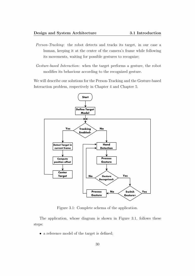
Person-Tracking : the robot detects and tracks its target, in our case a
human, keeping it at the center of the camera’s frame while following
its movements, waiting for possible gestures to recognize;
Gesture-based Interaction: when the target performs a gesture, the robot
modifies its behaviour according to the recognized gesture.
We will describe our solutions for the Person-Tracking and the Gesture-based
Interaction problem, respectively in Chapter 4 and Chapter 5.
Start
Define Target
Model
Yes
Hand
Detection
Compute
position offset
Process
Gesture
Detect Target in
current frame
No Gesture
Recognized?
Switch
Gesture?
No Yes
Center
Target
Tracking
Enabled?
Process
Gesture
Yes
No
Figure 3.1: Complete schema of the application.
The application, whose diagram is shown in Figure 3.1, follows these
steps:
• a reference model of the target is defined;
30

Design and System Architecture 3.1 Introduction
• tracking is enabled by default, hence the target is tracked over time
actuating the Kinect;
• if a particular gesture defined switch gesture is performed, the gesture-
driven interaction subsystem is enabled, the robot is re-oriented accord-
ing to the final position of the Kinect and sensor is no longer actuated;
• the robot performs actions according to the gestures performed by the
user;
• if the switch gesture is executed again, the Kinect is re-actuated to
perform tracking, while the interaction subsystem is paused.
Further on, we present the different components our system is made of.
In Section 3.2, we discuss in detail all the devices composing the hardware,
shown in Figure 3.2, while in Section 3.3 we present the software for control-
ling our platform.
Figure 3.2: A view of the system architecture composed of Erratic, Kinectand a Pan-Tilt Unit.
31
Design and System Architecture 3.2 Hardware Components
3.2 Hardware Components
As previously mentioned, in this section we present the hardware of our
platform, while providing the reasons of such choices: the first part addresses
the robotic platform, in the second one we provide a detailed description of
the sensor for our vision-based gesture-driven interaction, while in the last
topic we present a device to actuate the sensor.
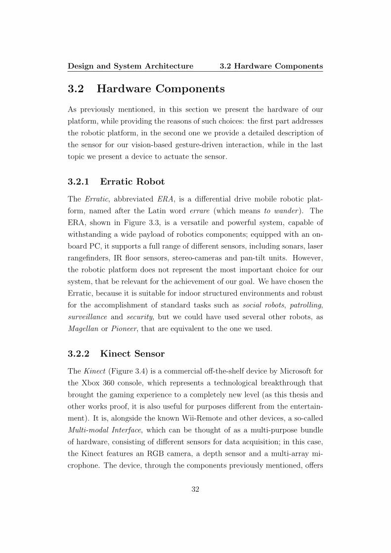
3.2.1 Erratic Robot
The Erratic, abbreviated ERA, is a differential drive mobile robotic plat-
form, named after the Latin word errare (which means to wander). The
ERA, shown in Figure 3.3, is a versatile and powerful system, capable of
withstanding a wide payload of robotics components; equipped with an on-
board PC, it supports a full range of different sensors, including sonars, laser
rangefinders, IR floor sensors, stereo-cameras and pan-tilt units. However,
the robotic platform does not represent the most important choice for our
system, that be relevant for the achievement of our goal. We have chosen the
Erratic, because it is suitable for indoor structured environments and robust
for the accomplishment of standard tasks such as social robots, patrolling,
surveillance and security, but we could have used several other robots, as
Magellan or Pioneer, that are equivalent to the one we used.
3.2.2 Kinect Sensor
The Kinect (Figure 3.4) is a commercial off-the-shelf device by Microsoft for
the Xbox 360 console, which represents a technological breakthrough that
brought the gaming experience to a completely new level (as this thesis and
other works proof, it is also useful for purposes different from the entertain-
ment). It is, alongside the known Wii-Remote and other devices, a so-called
Multi-modal Interface, which can be thought of as a multi-purpose bundle
of hardware, consisting of different sensors for data acquisition; in this case,
the Kinect features an RGB camera, a depth sensor and a multi-array mi-
crophone. The device, through the components previously mentioned, offers
32
Design and System Architecture 3.2 Hardware Components
Figure 3.3: A view of the ERA equipped with a Hokuyo URG Laser.
the players a new kind of interaction, a more natural interface based on user
motion, gestures and speech recognition.
The success of the Kinect, both in the videogames market and in the HRI
research, can be explained by two different reasons:
• Thanks to its capabilities, meaning gesture and speech recognition to-
gether with the motion capture system of multiple users, it represents
a technological milestone, presented as a consumer-level product;
• It constitutes a completely new type of user interface, which allows the
human, on the one side, to interact with the robotic system as with
another person and, on the other side, to have his hands free for other
interfaces, in the pursuit of more complex ways of interaction, requiring
the manipulation of a wide amount of different data.
33

Design and System Architecture 3.2 Hardware Components
Figure 3.4: A view of the Kinect.
RGB Camera
The RGB device installed in the Kinect consists of a traditional mono-
camera, similar to those used for web-cams and mobile phones, capable of
VGA resolution (640x480 pixels), operating at 30 frames per second.
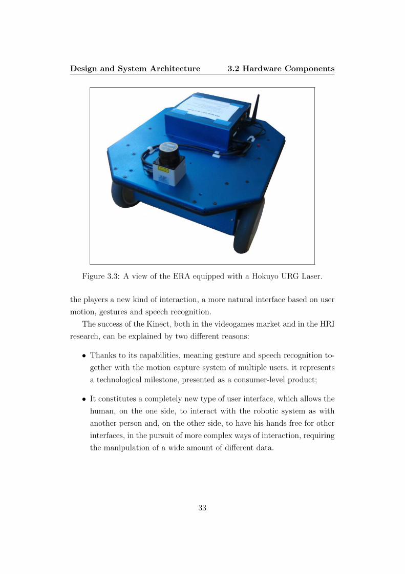
Depth Sensor
The depth sensor is the most important device featured by the Kinect and
the main reason of its success. Based on the technology of a range camera
developed by PrimeSense, an Israel company committed to the research and
development of control systems graspable-device independent, it consists of
two different components: an infrared laser transmitter and a monochrome
CMOS receiver. Following a pattern, the former projects infrared beams to-
wards the environment (see Figure 3.5 and Figure 3.6); the latter captures
the rays when travelling back and, depending on their time of flight, calcu-
lates the depth of the 3D space, providing a high-quality reconstruction of
the scene. Furthermore, it is very important to point out that the sensor is
34

Design and System Architecture 3.2 Hardware Components
capable of computing depth data under any ambient light conditions, even
pitch black.
Figure 3.5: The infrared rays projection on the scene, recognizable by thebright dots, which identifies also the field of view of the Kinect.
Microphone Array
The microphone array consists of four microphone capsules and operates with
each channel processing 16-bit audio at a sampling rate of 16 kHz, used to
calibrate the environment through the analysis of the sound reflections on
walls and objects.
3.2.3 Pan-Tilt Unit
The pan-tilt unit (Figure 3.7) is a system used to supply motion to sensors
installed upon it, usually stereo or mono cameras. Despite its simplicity, it
consists of a small chassis with two actuators, this device is extremely useful.
To understand its importance, we provide the following example. Think of a
35
Design and System Architecture 3.2 Hardware Components
Figure 3.6: View of the projection pattern of the laser trasmitter.
mobile robot, equipped with a camera, patrolling an environment in which
the mobility of the platform is reduced (e.g. for debris or crowd); now, let
us define the task the robot has to accomplish, which is to perform data
acquisition of the surroundings. At this point, we assume the robot cannot
move: if it is provided of a pan-tilt, the sensor can be moved independently
of the motion of the platform, so the task will be accomplished; otherwise,
since the motion of the camera is dependant on the one of the robot, the
camera will not move and the task will not be completed.
Pan-tilt units, whose usefulness we hope we convinced the reader of, pro-
vide two additional degrees of freedom to the sensor installed upon it, through
the following movements:
Pan motion: rotation on the horizontal plane, also known as panning plane,
analogous to the yaw rotation of an aircraft;
Tilt motion: rotation on the vertical plane, defined tilting plane, similar to
the pitch rotation of an aircraft.
36

Design and System Architecture 3.2 Hardware Components
Figure 3.7: Pan-Tilt system equipped on our ERA.
The reason why we used a pan-tilt in our system is represented by our
necessities to decouple the motion of the sensor from the movement of the
robot. Hence, through the actuated Kinect we can perform tracking of the
human, maintaining him in the center of the sensor’s reference frame, while
the robot can roam in the scene for other purposes, for example moving in
circles around the target to mark him. Although the sensor has its own
motorized pivot we used an external pan-tilt for two distinct reasons: on the
one hand, for the impossibility to perform a movement on the panning plane,
since the pivot provides motion only on the tilting plane, and, on the other
hand, for the limitations of the framework used to communicate with the
Kinect, which does not any support pivot control.
37

Design and System Architecture 3.3 Software Components
3.3 Software Components
In this section, we present the different software components we used to
control our system: Player is a low-level framework used to control both the
robotic platform and the pan-tilt unit, OpenNI is one the best SDKs available
to communicate with the Kinect and NITE is a powerful middleware, fully
integrable in OpenNI, for the gesture recognition part.
3.3.1 Player
Player 1 is a worldwide known framework, which provides a simple interface
for the control of robotic platforms, both real and simulated (in the second
case it is used alongside Stage or Gazebo, respectively a 2D and a 3D multi-
robot simulator). Based on the Client/Server paradigm, Player ”accepts”
control software modules written in any programming language, as long as
TCP sockets are supported, and can be executed on any computer connected
to the robot that has to be controlled.
It supports a wide range of robots (e.g. Roomba, Erratic, Magellan, Pio-
neer and many others) and plenty of different sensors (e.g. sonars, lasers, in-
frared transmitters/receivers). On the server side, Player communicates with
the devices by means of predefined drivers, providing the client with simple
and reusable interfaces, called proxies. This feature guarantees complete
portability of the clients on whichever robot, equipped with any supported
sensor.
For example (see Figure 3.8 and Figure 3.9) Player’s server may run on
a Magellan robot equipped with a SICK LMS-200 laser, while the client will
simply access two proxies, one called laser and the other called position,
which refers to the mobile robot base; thanks to the portability offered by
the framework, the same client could be used for an Erratic robot equipped
with a Hokuyo URG laser, because the difference of mobile base and sensor
is handled on the server side by Player, which will provide to the client the
same interfaces named previously.
1http://playerstage.sourceforge.net/
38
Design and System Architecture 3.3 Software Components
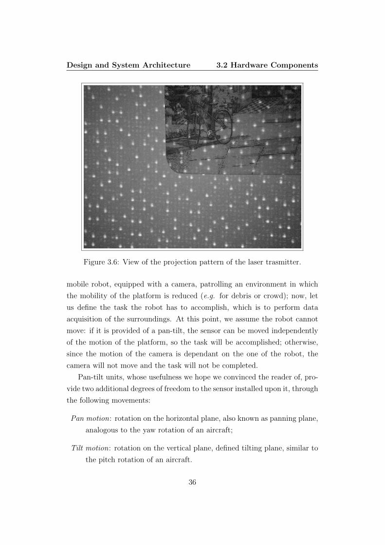
The low-level control of a robot relies on the motherboard and its con-
troller, which reads data (e.g. through USB connection) acquired by the
sensors and sends commands to the actuators; the high-level control, pro-
vided by Player server is performed using proxies like the following:
Player
Server
Player
Client
Application
Communication
through drivers
Communication
through TCP
connection
Communication
through client
proxy
(a) Player connection to an Er-ratic robot
Communication
through drivers
Communication
through TCP
connection
Communication
through client
proxy
Player
Server
Player
Client
Application
(b) Player connection to a Mag-ellan robot
Figure 3.8: Two examples of possible connection with two different robots.It is worth noting that, client-side, the interface provided is the same.
position2d : basic service to control the motion of the robot and to read,
via dead reckoning, based on motor encoders, the position of the robot
itself;
39

Design and System Architecture 3.3 Software Components
ptz proxy : provides control for 3 hobby-type servos, for example to command
the actuators of a pan-tilt-zoom camera.
Compared to the other frameworks presented further on, chosen for their
strengths with respect to other products, Player is an obvious choice when
one wants a direct and simple interaction with a robot.
The other possible approach is the implementation of the drivers for all
Communication
through drivers
Communication
through TCP
connection
Communication
through client
proxy
Player
Server
Player
Client
Application
(a) Player interfaced with aHokuyo Urg Laser
Communication
through drivers
Communication
through TCP
connection
Communication
through client
proxy
Player
Server
Player
Client
Application
(b) Player interfaced with a SICKLaser
Figure 3.9: Two examples of connection with two different laser sensors.Either in this case the Player provides client-side the same interface for bothsensors.
40
Design and System Architecture 3.3 Software Components
the devices installed in the robot itself; clearly, this approach is extremely
time consuming, feasible only when dealing with highly critical scenarios,
where it is preferable to design ad-hoc software instead of relying on third-
party frameworks. Moreover, using Player we always have the possibility
of testing our application in different scenarios, like rescue robotics, simply
changing the robot, without worrying about modifications to the software of
our implementation.
3.3.2 OpenNI
As explained in section 2.2, both HRI and human-computer interaction
are focusing towards a novel interaction paradigm, through communication
means which have to be natural and intuitive for the humans, defining the
so-called Natural Interaction. This is the main purpose of OpenNI 2, where
NI stands for Natural Interaction, a cross-platform framework developed
by PrimeSense, which provides APIs for implementing applications, mostly
based on speech/gesture recognition and body tracking.
OpenNI enables a two-directional communication with, on the one hand:
• Video and audio sensors for perceiving the environment (have to be
compliant with the standards of the framework)
• Middlewares which, once acquired data from the aforementioned sen-
sors, return meaningful informations, for example about the motion of
a target
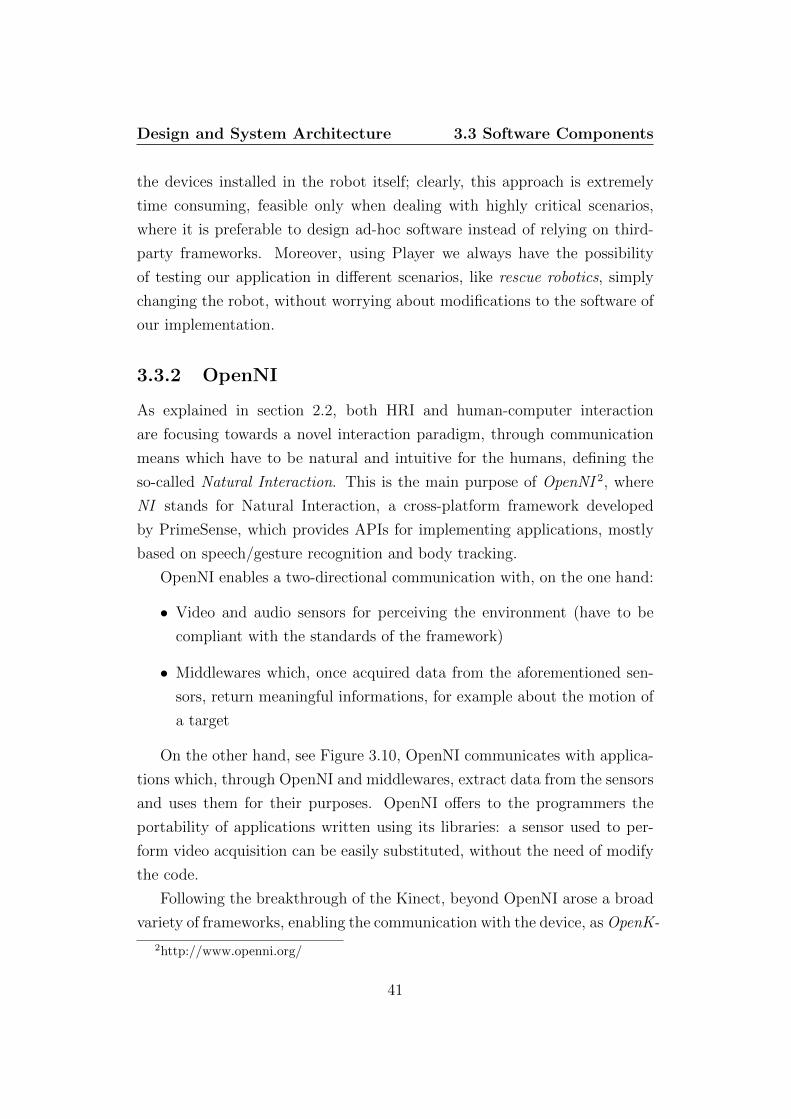
On the other hand, see Figure 3.10, OpenNI communicates with applica-
tions which, through OpenNI and middlewares, extract data from the sensors
and uses them for their purposes. OpenNI offers to the programmers the
portability of applications written using its libraries: a sensor used to per-
form video acquisition can be easily substituted, without the need of modify
the code.
Following the breakthrough of the Kinect, beyond OpenNI arose a broad
variety of frameworks, enabling the communication with the device, as OpenK-
2http://www.openni.org/
41
Design and System Architecture 3.3 Software Components
OpenNI
Application
Level
OpenNI
Interfaces
Sensor
Level
Middleware
Components
Application
Middleware
Component
A
Middleware
Component
B
Middleware
Component
C
Figure 3.10: Abstract view of the layers of OpenNI communication.
inect3 and Point Cloud Library4 (only to cite the most known). After a thor-
ough analysis of their strengths and weaknesses, we chose OpenNI, since it
was found out to be the most suitable framework for our application, both
in terms of usability and performance.
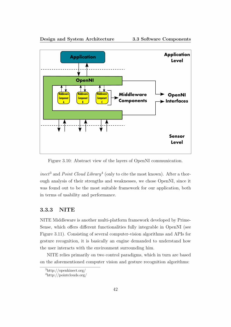
3.3.3 NITE
NITE Middleware is another multi-platform framework developed by Prime-
Sense, which offers different functionalities fully integrable in OpenNI (see
Figure 3.11). Consisting of several computer-vision algorithms and APIs for
gesture recognition, it is basically an engine demanded to understand how
the user interacts with the environment surrounding him.
NITE relies primarily on two control paradigms, which in turn are based
on the aforementioned computer vision and gesture recognition algorithms:
3http://openkinect.org/4http://pointclouds.org/
42
Design and System Architecture 3.3 Software Components
• Hand control : it occurs when a user interacts with his counterpart,
which can be a computer or a television, through hand gestures (e.g.
to browse media contents);
• Full body control : commonly associated with videogaming experiences,
the goal of this paradigm is the extraction of skeleton features to be
used as control inputs.
OpenNI
Application
Level
OpenNI
Interfaces
Sensor
Level
NITE
Engine
NITE
Controls Application
Figure 3.11: Layered view of NITE Middleware, focusing on its integrationwith OpenNI.
Instead of implementing a gesture-recognition algorithm, we decided to
use this framework for two reasons: on the one side, it is designed to com-
municate with the Kinect sensor, on the other side it provides an easy-to-use
and robust engine for the recognition of different gestures.
43
Design and System Architecture 3.3 Software Components
3.3.4 OpenCV
OpenCV 5, Open-source computer-vision library, is a very powerful frame-
work developed by Willow Garage, which offers several APIs mainly focused
towards real-time computer vision. It features a wide range of functions,
for many different purposes as: image transformations, machine-learning ap-
proaches for detection and recognition, tracking and features matching.
For the scope of our application, this framework has been used during
the tests of the person-tracking part of the application, to visualize the data
acquired by the Kinect and to output the results of the different algorithms
implemented.
5http://opencv.willowgarage.com/wiki/
44

Chapter 4
Person-Tracking
4.1 Introduction
One of the requirements for an effective human-robot interaction level is
the achievement of a significant degree of awareness between the entities
involved; from the machine perspective, a method to make a robot aware of
the environment is to provide it with sensors, to acquire data from the world,
and algorithms, to interpret these data in meaningful ways. In our case, on
the one hand the sensor is the Kinect device, already introduced in Chapter
3. On the other hand, a set of computer-vision based algorithms guarantees
the awareness of robot’s counterpart, the human.
In this chapter we present our tracking subsystem, shown in Figure 4.1,
through the investigation of three different approaches, analysing which tech-
nique exhibits optimal performance in terms of person tracking success rate,
according to the novelty of the hardware configuration presented in the pre-
vious chapter. In Section 4.2 we discuss our first approach, based on the
tracking of the user’s center of mass. Section 4.3 addresses a modified ver-
sion of the previous implementation, by adding a proportional controller to
command the pan-tilt actuators. Finally, in Section 4.4, we detail a com-
pletely different approach, based on blob tracking.
45
Person-Tracking 4.2 CoM Tracking
Start
Define Target
Model
Detect Target in
current frame
Compute
position offset
Center
Target
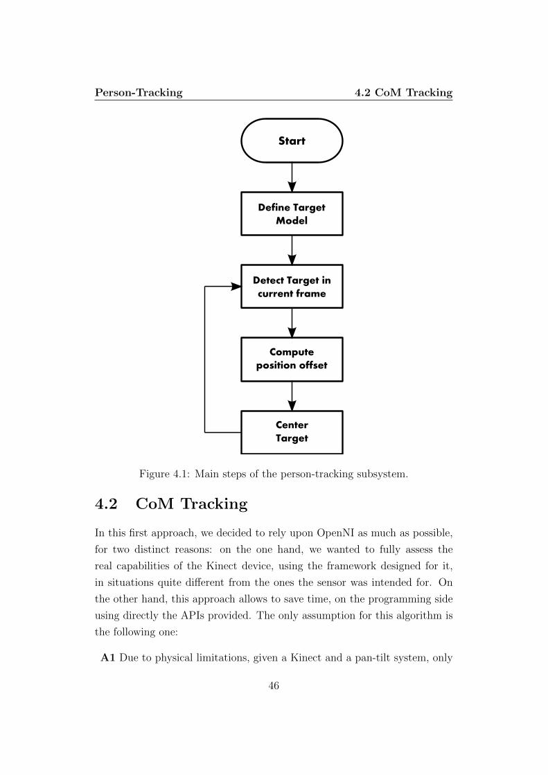
Figure 4.1: Main steps of the person-tracking subsystem.
4.2 CoM Tracking
In this first approach, we decided to rely upon OpenNI as much as possible,
for two distinct reasons: on the one hand, we wanted to fully assess the
real capabilities of the Kinect device, using the framework designed for it,
in situations quite different from the ones the sensor was intended for. On
the other hand, this approach allows to save time, on the programming side
using directly the APIs provided. The only assumption for this algorithm is
the following one:
A1 Due to physical limitations, given a Kinect and a pan-tilt system, only
46
Person-Tracking 4.2 CoM Tracking
one target can be tracked at a time (although there can be more than
one on the scene).
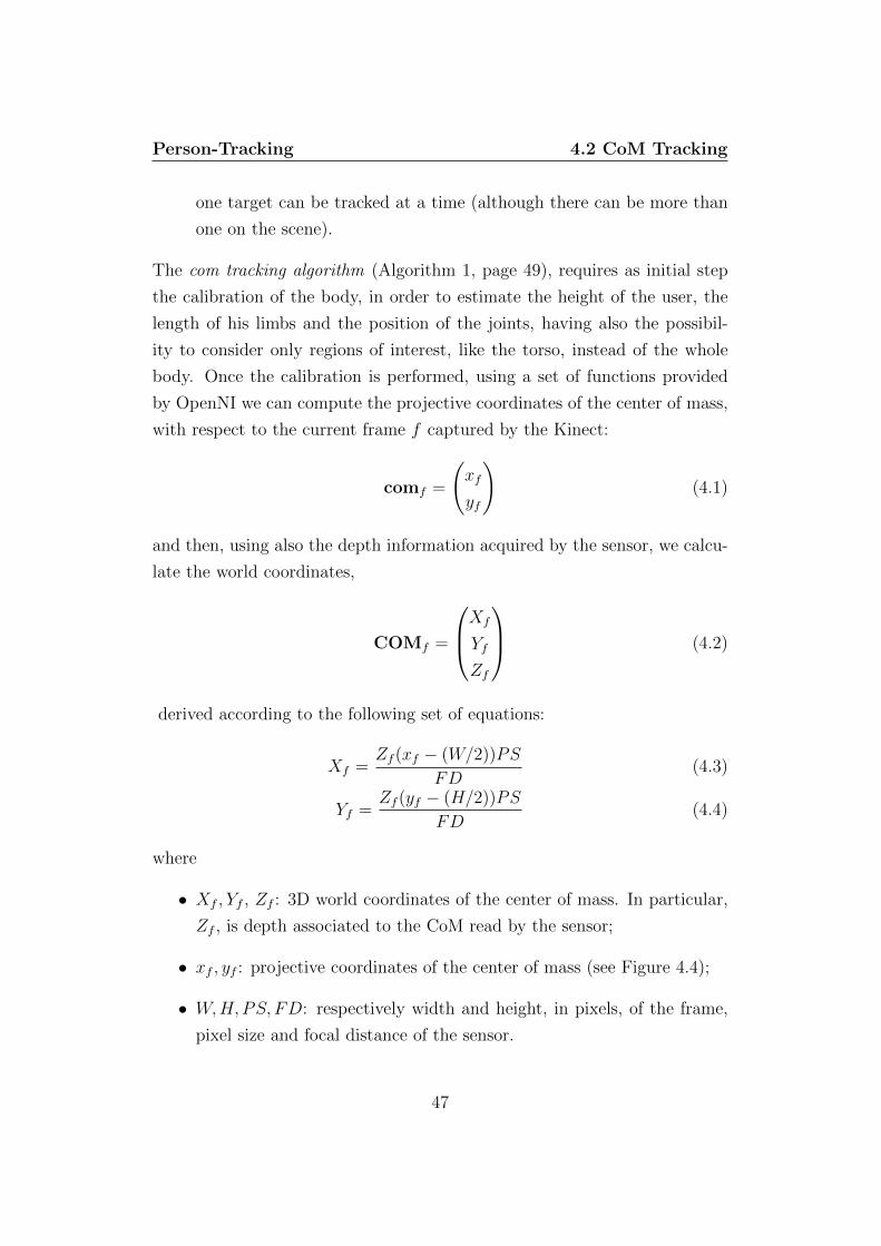
The com tracking algorithm (Algorithm 1, page 49), requires as initial step
the calibration of the body, in order to estimate the height of the user, the
length of his limbs and the position of the joints, having also the possibil-
ity to consider only regions of interest, like the torso, instead of the whole
body. Once the calibration is performed, using a set of functions provided
by OpenNI we can compute the projective coordinates of the center of mass,
with respect to the current frame f captured by the Kinect:
comf =
(xf
yf
)(4.1)
and then, using also the depth information acquired by the sensor, we calcu-
late the world coordinates,
COMf =
Xf
Yf
Zf
(4.2)
derived according to the following set of equations:
Xf =Zf (xf − (W/2))PS
FD(4.3)
Yf =Zf (yf − (H/2))PS
FD(4.4)
where
• Xf , Yf , Zf : 3D world coordinates of the center of mass. In particular,
Zf , is depth associated to the CoM read by the sensor;
• xf , yf : projective coordinates of the center of mass (see Figure 4.4);
• W,H,PS, FD: respectively width and height, in pixels, of the frame,
pixel size and focal distance of the sensor.
47
Person-Tracking 4.2 CoM Tracking
XZ
Y
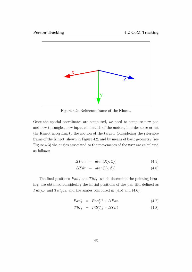
Figure 4.2: Reference frame of the Kinect.
Once the spatial coordinates are computed, we need to compute new pan
and new tilt angles, new input commands of the motors, in order to re-orient
the Kinect according to the motion of the target. Considering the reference
frame of the Kinect, shown in Figure 4.2, and by means of basic geometry (see
Figure 4.3) the angles associated to the movements of the user are calculated
as follows:
∆Pan = atan(Xf , Zf ) (4.5)
∆Tilt = atan(Yf , Zf ) (4.6)
The final positions Panf and Tiltf , which determine the pointing bear-
ing, are obtained considering the initial positions of the pan-tilt, defined as
Panf−1 and Tiltf−1, and the angles computed in (4.5) and (4.6):
Pantf = Pant−1
f + ∆Pan (4.7)
Tilttf = Tiltt−1f−1 + ∆Tilt (4.8)
48
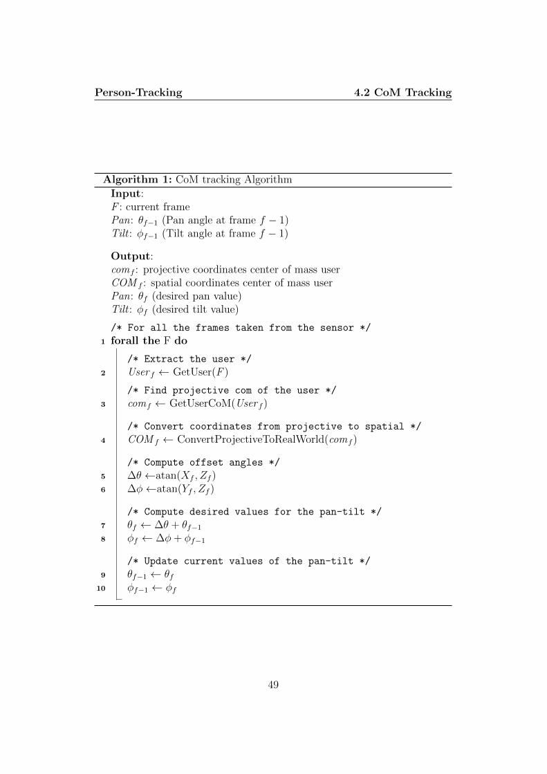
Person-Tracking 4.2 CoM Tracking
Algorithm 1: CoM tracking Algorithm
Input:F : current framePan: θf−1 (Pan angle at frame f − 1)Tilt : φf−1 (Tilt angle at frame f − 1)
Output:comf : projective coordinates center of mass userCOM f : spatial coordinates center of mass userPan: θf (desired pan value)Tilt : φf (desired tilt value)
/* For all the frames taken from the sensor */
1 forall the F do
/* Extract the user */
2 User f ← GetUser(F )
/* Find projective com of the user */
3 comf ← GetUserCoM(User f )
/* Convert coordinates from projective to spatial */
4 COM f ← ConvertProjectiveToRealWorld(comf )
/* Compute offset angles */
5 ∆θ ←atan(Xf , Zf )6 ∆φ←atan(Yf , Zf )
/* Compute desired values for the pan-tilt */
7 θf ← ∆θ + θf−1
8 φf ← ∆φ+ φf−1
/* Update current values of the pan-tilt */
9 θf−1 ← θf10 φf−1 ← φf
49

Person-Tracking 4.3 CoM Tracking with P Controller
Z
X
pan C
N
O
Figure 4.3: ∆Pan computation: CN represents the position offset of thetarget between previous and current frame, OC is the depth of the targetin the current frame. The angle is derived computing the arctangent of CNover OC. [∆Tilt is computed analogously, with respect to Y and Z axes]
4.3 CoM Tracking with P Controller
After several tests involving different people acting as targets, we discarded
the former approach due to an unexpected high percentage of target loss,
caused mostly by fast movements of the user, related to the nature of the
underlying level of algorithms the OpenNI functions are based on. The ra-
tionale assumption behind the design of these algorithms requires the Kinect
to be fixed on a surface (e.g. a table or a TV, where it is most likely to be
seen), or moving smoothly (e.g. 3D reconstruction of a static object). In our
case such a hypothesis is rejected by mounting the sensor on top of a pan-
tilt, controlling the motors towards the desired final position, without any
chance to slow down the execution of the displacement. Hence, the system
could not guarantee either a slow or a smooth movement, once commanded.
To solve the problem of the tracked target loss, we designed an alternative
version of the previous algorithm, called com tracking with P controller algo-
50

Person-Tracking 4.4 Blob Tracking
Figure 4.4: Result of user’s detection and computation of his center of mass,labeled by 1, using OpenNI.
rithm (Algorithm 2, page 52), adding a proportional controller, in order to
achieve the smoothness we were looking for and to reduce, possibly to zero,
the probability of target loss.
4.4 Blob Tracking
Although the idea of a controller appears as the optimal approach to solve
the target loss issue due to shaky movements, either in this case the out-
come was not so satisfying as we expected; rather than discarding the whole
approach, and its implementation, we attempted to further modify it, sub-
stituting the existing controller with a PID, proportional-integral-derivative,
then spending time to tune all the parameters of the algorithm and of the
controller.
However, these modifications did not guarantee us that high degree of
robustness we needed for our purposes, mainly due to limitations of the
framework (meaning the required static position of the Kinect). Therefore,
51

Person-Tracking 4.4 Blob Tracking
Algorithm 2: CoM tracking with P controller Algorithm
Input:F : current framePan: θf−1 (Pan angle at frame f − 1)Tilt : φf−1 (Tilt angle at frame f − 1)K p: proportional gain of the controller
Output:comf : projective coordinates center of mass userCOM f : spatial coordinates center of mass userPan: θf (desired pan value)Tilt : φf (desired tilt value)
/* For all the frames taken from the sensor */
1 forall the F do
/* Extract the user */
2 User f ← GetUser(F )
/* Find projective com of the user */
3 comf ← GetUserCoM(User f )
/* Convert coordinates from projective to spatial */
4 COM f ← ConvertProjectiveToRealWorld(comf )
/* Compute offset angles */
5 ∆θ ←atan(Xf , Zf )6 ∆φ←atan(Yf , Zf )
/* Compute desired values for the pan-tilt */
7 θf ← ∆θ + θf−1
8 φf ← ∆φ+ φf−1
9 while (|θf − θf−1| ≥ ε) do
/* Update current pan */
10 θf ← Kpθf−1
11 while (|φf − φf−1| ≥ ε) do
/* Update current tilt */
12 φf−1 ← Kpφf−1
/* Update current values of the angles */
13 θf−1 ← θf14 φf−1 ← φf
52
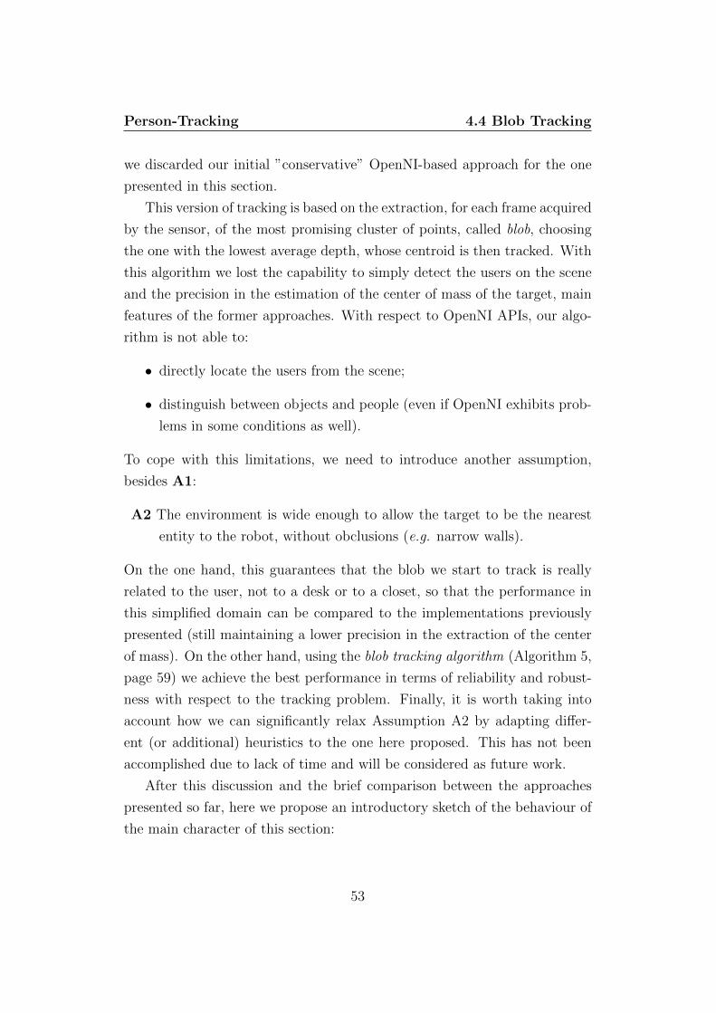
Person-Tracking 4.4 Blob Tracking
we discarded our initial ”conservative” OpenNI-based approach for the one
presented in this section.
This version of tracking is based on the extraction, for each frame acquired
by the sensor, of the most promising cluster of points, called blob, choosing
the one with the lowest average depth, whose centroid is then tracked. With
this algorithm we lost the capability to simply detect the users on the scene
and the precision in the estimation of the center of mass of the target, main
features of the former approaches. With respect to OpenNI APIs, our algo-
rithm is not able to:
• directly locate the users from the scene;
• distinguish between objects and people (even if OpenNI exhibits prob-
lems in some conditions as well).
To cope with this limitations, we need to introduce another assumption,
besides A1:
A2 The environment is wide enough to allow the target to be the nearest
entity to the robot, without obclusions (e.g. narrow walls).
On the one hand, this guarantees that the blob we start to track is really
related to the user, not to a desk or to a closet, so that the performance in
this simplified domain can be compared to the implementations previously
presented (still maintaining a lower precision in the extraction of the center
of mass). On the other hand, using the blob tracking algorithm (Algorithm 5,
page 59) we achieve the best performance in terms of reliability and robust-
ness with respect to the tracking problem. Finally, it is worth taking into
account how we can significantly relax Assumption A2 by adapting differ-
ent (or additional) heuristics to the one here proposed. This has not been
accomplished due to lack of time and will be considered as future work.
After this discussion and the brief comparison between the approaches
presented so far, here we propose an introductory sketch of the behaviour of
the main character of this section:
53

Person-Tracking 4.4 Blob Tracking
1. for each frame f , the algorithm looks for the pixel with minimum depth
in a region of interest (ROI ), defined around the center of the image
acquired by the Kinect;
2. background elimination of the scene is performed only in the ROI, by
segmenting the image and maintaining only the foreground points that
fall in a given distance threshold with respect to the minimum depth
computed before;
3. starting from the segmented frame obtained, the algorithm clusters the
foreground points creating different blobs (in the best scenario, only
one blob will be created);
4. the most promising blob is selected, whose centroid, represented anal-
ogously to a center of mass, as shown in (4.1) and (4.2), is computed
and then tracked.
Figure 4.5: Depth informations of the scene acquired by the Kinect.
Lowering the initial frame to the region of interest corresponds to a reduction
of the field of view of the sensor and is performed to avoid as much as possible
54

Person-Tracking 4.4 Blob Tracking
problems that may arise in case the assumption A2 does not completely hold.
The first two steps presented in the sketch are performed using the background
elimination algorithm (Algorithm 3, page 56), which takes as input the frame
captured by the Kinect, returning a cropped and segmented version of it, by
following these steps:
1. it takes the frame acquired by the sensor, shown in Figure 4.5, and
creates a new frame associated to the ROI of the original image;
2. it looks for the pixel of the new frame with the lowest depth;
3. it re-scans the segmented frame, separating the background pixels (set
to black) from the foreground ones (set to white) (see Figure 4.6).
Figure 4.6: Background elimination performed by the algorithm.
The image returned by the background elimination step is then used as in-
put for another algorithm, called blob expansion algorithm (Algorithm 4,
page 57), whose purpose is to perform clustering on all the points that lie in
the ROI, according to the following steps:
1. all the pixels are marked as unvisited : being this algorithm recursive,
this is done to avoid possible stack overflow problems that may arise
re-visiting always the same pixels;
2. it scans the segmented frame starting from the origin of the image;
3. every time it analyses an unvisited foreground pixel, it creates a blob,
setting the pixel as its centroid;
55

Person-Tracking 4.4 Blob Tracking
Algorithm 3: Background Elimination Algorithm
Input:F : current framepi,jf : k-th pixel of the current framedepthkf : depth associated to the k-th pixelminW : lower bound of the width of the ROIMaxW : upper bound of the width of the ROIminH : lower bound of the height of the ROIMaxH : upper bound of the height of the ROI
Output:SF : segmented frameI sf : set containing foreground pixels of the ROIOsf : set containing background pixels of the ROI
/* For all the frames taken from the sensor */
1 forall the F do
/* Copy ROI from the original frame */
2 SF← CopyROI(F )
/* Compute minimum depth in the ROI */
3 LeastDepthf ← GetLeastDepth(SF )
/* Scan all the pixels */
4 forall the pi,jf do
/* Check if the pixel lies into the ROI */
5 if ((minW ≤ i ≤ MaxW) ∧ (minH ≤ j ≤ MaxH)) then
/* Check the depth threshold */
6 if depthkf − LeastDepth ≤ ε then
/* Store the pixel in the foreground set */
7 I sf ← pi,jf
8 else
/* Store the pixel in the background set */
9 Osf ← pi,jf
/* Modify ROI */
10 SF f ← BuildFilteredImage(I sf , Osf )
56

Person-Tracking 4.4 Blob Tracking
Algorithm 4: Blob Expansion Algorithm
Input:SF : segmented framepksf : k-th pixel of the segmented framebisf : i-th blob createddepthksf : depth associated to the k-th pixelunsf
: n-th neighbour of the k-th pixeldepthnsf
: depth associated to the n-th neighbourI sf : set containing foreground pixels of the ROIOsf : set containing background pixels of the ROI
Output:B : set containing all the blobs clustered
/* For each segmented frame */
1 forall the SF do
/* Scan all the pixels */
2 forall the pksf do
/* Check if the pixel has been visited
/* and belongs to the foreground */
3 if ((pksf is Unvisited ) ∧ (pksf ∈Isf )) then
/* Create a new blob and set the centroid */
4 blobisf ← CreateBlob(pksf )
/* Check all the neighbours of pksf */
5 forall the unsfdo
/* Check the distance between pixels */
6 if |depthnsf − depthksf | ≤ ε then
/* Update size of the blob */
7 Grow(bisf )
/* Recursive expansion of the blob */
8 BlobExpansion(blobisf )
/* Store the blob */
9 B sf ←blobisf
57

Person-Tracking 4.4 Blob Tracking
4. starting from the centroid, the algorithm visits all its neighbours, try-
ing to recursively expand the blob as much as possible, maintaining a
rectangular/square shape;
5. when the blob cannot be further expanded, it looks for another unvis-
ited foreground pixel and, if found, it repeats the previous steps until
the whole image has been scanned;
6. it finally returns a set containing all the blobs created.
Figure 4.7: Approximation to a rectangle/square of the most promising blobreturned by the blob expansion algorithm.
After the execution of the aforementioned algorithm, we choose the blob
(if the execution returned more than one), with the lowest average depth,
computed with respect to the number of pixel belonging to that blob. Then,
since the blob is expanded approximating its shape to a rectangle/square (see
Figure 4.7) it is quite easy to geometrically derive the projective coordinates
of the centroid. At this stage, using (4.3) and (4.4) we can compute the
world coordinates, and finally, according to (4.5) and (4.6), we obtain the
commands for the pan-tilt system to re-align the Kinect in order to keep the
target in the center of its frame.
In Section 6.2 we detail the experiments, and relative results, performed to
assess the reliability of the tracking subsystem under static conditions of the
robot, only actuating the Kinect.
58
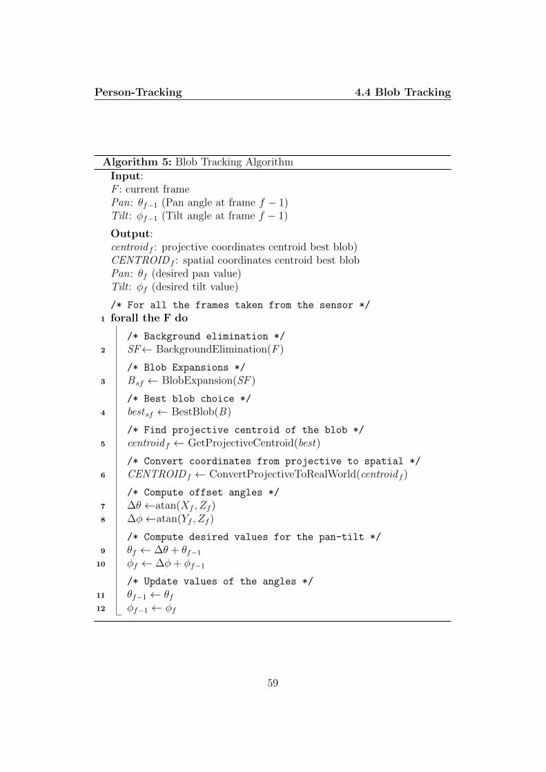
Person-Tracking 4.4 Blob Tracking
Algorithm 5: Blob Tracking Algorithm
Input:F : current framePan: θf−1 (Pan angle at frame f − 1)Tilt : φf−1 (Tilt angle at frame f − 1)
Output:centroid f : projective coordinates centroid best blob)CENTROIDf : spatial coordinates centroid best blobPan: θf (desired pan value)Tilt : φf (desired tilt value)
/* For all the frames taken from the sensor */
1 forall the F do
/* Background elimination */
2 SF← BackgroundElimination(F )
/* Blob Expansions */
3 B sf ← BlobExpansion(SF )
/* Best blob choice */
4 bestsf ← BestBlob(B)
/* Find projective centroid of the blob */
5 centroid f ← GetProjectiveCentroid(best)
/* Convert coordinates from projective to spatial */
6 CENTROIDf ← ConvertProjectiveToRealWorld(centroid f )
/* Compute offset angles */
7 ∆θ ←atan(Xf , Zf )8 ∆φ←atan(Yf , Zf )
/* Compute desired values for the pan-tilt */
9 θf ← ∆θ + θf−1
10 φf ← ∆φ+ φf−1
/* Update values of the angles */
11 θf−1 ← θf12 φf−1 ← φf
59

Chapter 5
Gesture-driven Interaction
5.1 Introduction
In Chapter 2 we presented the gesture recognition problem addressing a set
of different techniques for the implementation of a gesture classifier as well
as several application fields.
According to our motivations for a friendlier robot to interact with, which
provides simpler interfaces usable not only by system experts, in this chap-
ter we propose the implementation of our gesture-driven interaction system,
starting from the following premises:
A3 to achieve a simply usable gesture-based interaction system, we do not
make use of any graspable user interface, aiming to implement a vision-
based gesture recognizer. Of course we are aware that this requires
the camera to continuously point the user, but this is realistic for our
application;
A4 within the whole set of possible gestures, already discussed in Sec-
tion 2.4, our system is designed to recognize only hand gestures;
A5 we analyse only a small subset of all the possible hand gestures a user can
perform, mapping these gestures with actions the robot will execute.
We begin the investigation of this subsystem providing a mathematical rep-
resentation of gesture, suitable for a vision-based system:
60

Gesture-driven Interaction 5.2 Recognizable Gestures
Definition 5.1. Let T ∈ Z be a sampling interval. A sample gesture G
consists of a time-ordered sequence of positions p(kT) representing the hand’s
state, defined as:
((p(kT )), 0 ≤ k ≤ n, n ∈ N
According to this definition, the input provided to the recognition sub-
system is a gesture represented through a sequence of three-dimensional co-
ordinates:
p(t) =
pxpypz
(5.1)
indicating the hand’s position at the sampling time t = kT .
To deal with the hand tracking and the gesture processing we rely on
NITE, the middleware presented in Section 3.3.3. The framework detects the
hand in the three-dimensional scene read by the Kinect and, by tracking the
centroid of the hand, recognizes those gestures meaningful for our purposes.
This chapter consists of two macro-sections: in Section 5.2 we detail the
set of gestures our system is able to recognize, also providing a mathematical
and a visual representations, while Section 5.3 presents the mapping of such
gestures with a set of different actions for human-robot interaction driven by
gestures.
5.2 Recognizable Gestures
In this section we present the gestures our system is able to classify. Our
vocabulary consists of the six gesture presented below:
• steady;
• swipe (up - down - right - left);
• wave.
For each gesture, NITE provides a classifier featuring different adjustable
parameters, in order to modify the recognition with respect to requirements
61

Gesture-driven Interaction 5.2 Recognizable Gestures
of the application using the middleware. Furthermore, the presence of such
parameters is important for another reason: as we discuss later on, there are
ambiguities among the swipes in the horizontal plane and the wave gesture
leading to wrong classifications, that can be solved with an accurate tuning.
The steady gesture, shown in Figure 5.1, is performed raising one hand with
the palm facing forward and maintaining a static position for a certain time
interval. The classifier of this gesture, called steady detector, allows to adjust
a tolerance threshold of the position with respect to the three axes, being
unlikely that hands maintain a steady position without millimetric displace-
ments, and the minimal duration of the gesture, in terms of milliseconds and
frames.
Static
Position
Figure 5.1: Illustration of the steady gesture.
The swipe is a linear motion performed in the x-y plane, moving the hand
along one out of the four following directions: up, down, left, right (Fig-
ure 5.2 and Figure 5.3). The classifiers of these gestures are respectively
called: swipe-up detector, swipe-down detector, swipe-right detector, swipe-
62

Gesture-driven Interaction 5.2 Recognizable Gestures
left detector. Each of them permits the configuration of the required velocity
and time duration of the gesture in order to be recognized and to set a time
interval during which the hand has to stay still in the final position of the ges-
ture. This last parameter is quite important to achieve a robust recognition
of the wave gesture, because horizontal swipes classifiers exhibit problems of
false recognition when the user waves.
Initial
Position
Final
Position
Intermediate
Position
(a) Execution of the right swipe
Initial
Position
Final
Position
Intermediate
Position
(b) Execution of the left swipe
Figure 5.2: The execution of the swipes along the horizontal plane.
63

Gesture-driven Interaction 5.2 Recognizable Gestures
Initial
Position
Final
Position
Intermediate
Position
(a) Execution of the up swipe
Final
Position
Initial
Position
Intermediate
Position
(b) Execution of the down swipe
Figure 5.3: The execution of the swipes along the vertical plane.
This is due to the fact that the wave gesture, whose execution is shown in
Figure 5.4, is performed through a continuous sequence of several right and
left swipes (or left and right swipes), without intermediate or specific final
positions. Hence, if the classifiers of right and left swipes are not properly
configured, the execution of a wave could generate possible false recognition
64
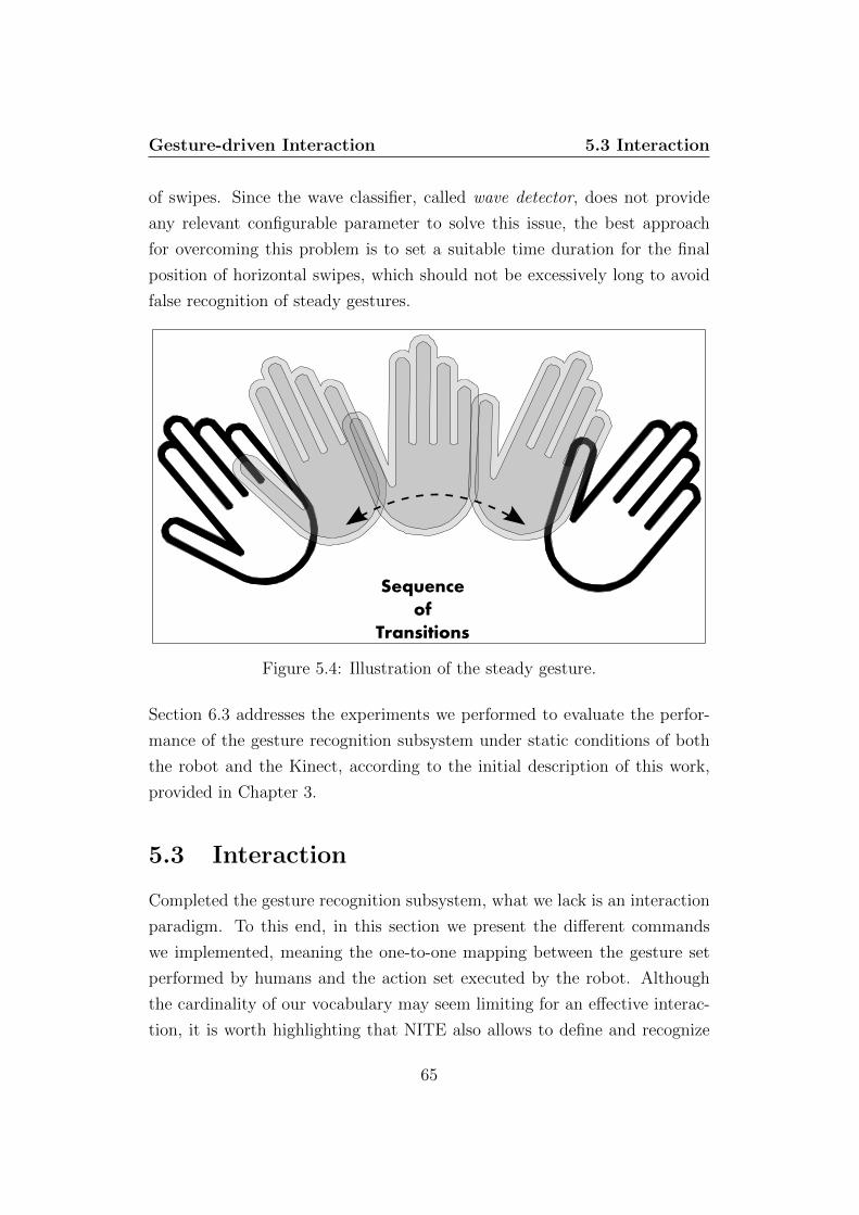
Gesture-driven Interaction 5.3 Interaction
of swipes. Since the wave classifier, called wave detector, does not provide
any relevant configurable parameter to solve this issue, the best approach
for overcoming this problem is to set a suitable time duration for the final
position of horizontal swipes, which should not be excessively long to avoid
false recognition of steady gestures.
Sequence
of
Transitions
Figure 5.4: Illustration of the steady gesture.
Section 6.3 addresses the experiments we performed to evaluate the perfor-
mance of the gesture recognition subsystem under static conditions of both
the robot and the Kinect, according to the initial description of this work,
provided in Chapter 3.
5.3 Interaction
Completed the gesture recognition subsystem, what we lack is an interaction
paradigm. To this end, in this section we present the different commands
we implemented, meaning the one-to-one mapping between the gesture set
performed by humans and the action set executed by the robot. Although
the cardinality of our vocabulary may seem limiting for an effective interac-
tion, it is worth highlighting that NITE also allows to define and recognize
65

Gesture-driven Interaction 5.3 Interaction
complex sequences of gestures, permitting to increase the number of possible
commands.
When the gesture performed by the user is recognized, the gesture-driven
interaction subsystem, shown in Figure 5.5, communicates which action the
robot has to execute, according to the mapping we defined.
Hand Detection
Process Gesture
No GestureRecognized?
Perform Action
Yes
SwitchGesture?
No Yes
Enable Tracking
Figure 5.5: Main steps of the gesture-driven interaction subsystem.
We distinguished the behaviour of the robot with respect to the recognized
gestures, as follows:
• steady : this is used to switch between the user-tracking, executed actu-
ating the Kinect, and gesture-driven interaction behaviours. We relied
on the steady gesture for two distinct reasons: on the one hand, it is
66
Gesture-driven Interaction 5.3 Interaction
easily executable and does not suffer of problems related to the orien-
tation of the device with respect to the user. On the other hand, it
is a semantically meaningful gesture humans use to make other people
stop;
• swipe down: when this gesture is recognized, the robot starts to move
forward approaching the user, stopping its motion if the distance be-
tween the two entities is lower than a certain threshold. We defined
this mapping because a down swipe resembles the gesture we perform
to let other people come closer to us;
• swipe up: once the system recognizes this gesture, the robot starts to
move backward driving away from the user, stopping its motion if the
distance becomes greater than a certain threshold. As for the up swipe,
we chose this mapping for the resemblance with the gesture we perform
to push away people;
• swipe right, swipe left : these gestures are used as interrupts, which
force the robot to stop its motion for safety reasons (e.g. too near to
wall or other people), disregarding the actions it is executing. Finally,
if we think of a robot going towards a wall’s corner, it is quite intuitive
to react by swiping left or right as in the act to suggest it to move
farther from that dangerous spot;
• wave: this gesture enables the most interesting behaviour we imple-
mented. Once it is recognized, the robot starts to track and follow
the user over time. It is worth remembering that when the gesture
interaction subsystem is enabled the Kinect is no longer actuated by
the pan-tilt, aligned with respect to the robot’s orientation, pointing
forward. Hence, in this situation the person-tracking is achieved not
moving the sensor but instead moving the whole platform, command-
ing the angular velocity to keep the user in the center of the camera
frame.
The human-following algorithm (Algorithm 6, page 69), performs the user
tracking moving the whole robotic platform instead of re-orienting only the
67

Gesture-driven Interaction 5.3 Interaction
Kinect. The algorithm iteratively executes the steps reported below, until
an interrupt gesture, which stops the robot, or the switch gesture, that re-
enables the tracking performed actuating the sensor, is performed by the
user:
1. it computes the angular offset between the center of the Kinect’s refer-
ence frame, which coincides with the one of the robot, and the centroid
of the blob associated to the target;
2. using Player functions, motors are controlled in linear speed and jog
according to pre-defined thresholds;
3. every 30 milliseconds, that is, the working rate of the gesture recog-
nition subsystem, the angular offset is corrected and the distance is
checked against the threshold;
4. if the distance is below the threshold, the robot only corrects its an-
gular offset, where present; otherwise, the robot will maintain a static
position until the user moves again.
This human-following behaviour is relevant because, on the one side, it rep-
resents a meaningful form of interaction between humans and robots and, on
the other side, allows us to assess the robustness of the system in dynamic
conditions both for the tracking and the gesture subsystems, through the
experimental evaluations we will introduce in Section 6.4.
68

Gesture-driven Interaction 5.3 Interaction
Algorithm 6: User Following Algorithm
Input:Pan: θrobot (Current yaw of the robot)
/* Follow the user over time */
1 while (Gesture!=STOP) do
/* If the user waved, start following */
2 if (Gesture!=WAVE) then
/* Compute offset angles */
3 ∆θrobot ←atan(Xuser, Zuser)
/* Check distance between user and robot */
4 while ( distance ≥ ε) do
/* Check angular offset */
5 if |θd − θrobot| ≥ ε then
/* Set angular and linear velocities */
6 robot← SetSpeed(lin vel, ang vel)
/* If angular offset < threshold */
7 if |θd − θrobot| ≤ ε then
/* Set angular velocity to 0 */
8 robot← SetSpeed(lin vel, 0)
/* If angular offset > threshold and distance <
threshold */
9 if |θd − θrobot| ≥ ε then
/* Set linear velocity to 0 */
10 robot← SetSpeed(0, ang vel)
69

Part III
Results
70

Chapter 6
Experiments
6.1 Introduction
In this chapter we detail the results obtained evaluating the performance
of the platform presented in this thesis. We performed three typologies of
experiments, in order to evaluate the following aspects of our work:
1. robustness of the person tracking subsystem;
2. reliability of the gesture recognition subsystem;
3. performance of our platform with both the subsystems integrated, in a
person following task.
In each of the following sections, we will first detail the experimental setup
and then discuss the results of the tests performed, so far.
71
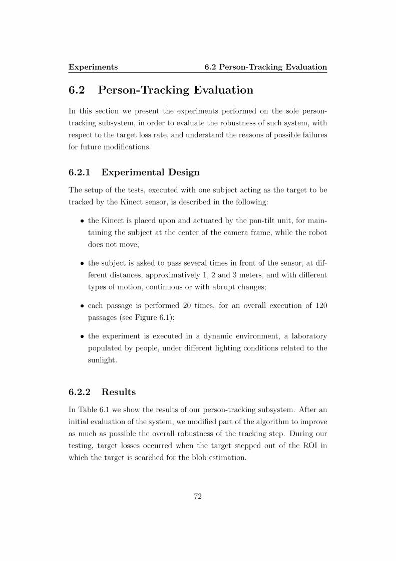
Experiments 6.2 Person-Tracking Evaluation
6.2 Person-Tracking Evaluation
In this section we present the experiments performed on the sole person-
tracking subsystem, in order to evaluate the robustness of such system, with
respect to the target loss rate, and understand the reasons of possible failures
for future modifications.
6.2.1 Experimental Design
The setup of the tests, executed with one subject acting as the target to be
tracked by the Kinect sensor, is described in the following:
• the Kinect is placed upon and actuated by the pan-tilt unit, for main-
taining the subject at the center of the camera frame, while the robot
does not move;
• the subject is asked to pass several times in front of the sensor, at dif-
ferent distances, approximatively 1, 2 and 3 meters, and with different
types of motion, continuous or with abrupt changes;
• each passage is performed 20 times, for an overall execution of 120
passages (see Figure 6.1);
• the experiment is executed in a dynamic environment, a laboratory
populated by people, under different lighting conditions related to the
sunlight.
6.2.2 Results
In Table 6.1 we show the results of our person-tracking subsystem. After an
initial evaluation of the system, we modified part of the algorithm to improve
as much as possible the overall robustness of the tracking step. During our
testing, target losses occurred when the target stepped out of the ROI in
which the target is searched for the blob estimation.
72

Experiments 6.3 Gesture Recognition Evaluation
1m
2m
3m
Figure 6.1: Illustration of the tracking experiment design.
Distance MotionSmooth Abrupt
≈ 1 meter 100%(20/20) 100%(20/20)≈ 2 meters 100%(20/20) 95%(19/20)≈ 3 meters 95%(19/20) 85%(17/20)
Table 6.1: Person-tracking success rate with respect to different distancesand motions.
6.3 Gesture Recognition Evaluation
This section is dedicated to the experiments executed to assess the reliability
of the gesture recognition subsystem, disabling the person-tracking system,
through the assessment of the recognition success rate with respect to each
gesture presented in Chapter 5.
6.3.1 Experimental Design
For these tests we asked to ten different subjects, aged 27 years old on aver-
age, to perform all the gestures our system is able to recognize. The pool of
subjects consisted of seven males and three females, non-expert either of the
Kinect or our work. Each experiment is articulated as follows:
73

Experiments 6.4 Joint Evaluation
Subject GestureSteady Wave Swipe Up Swipe Down Swipe Right Swipe Left
# 1 100%(5/5) 100%(5/5) 100%(5/5) 100%(5/5) 100%(5/5) 100%(5/5)# 2 100%(5/5) 100%(5/5) 80%(4/5) 60%(3/5) 100%(5/5) 100%(5/5)# 3 100%(5/5) 100%(5/5) 100%(5/5) 100%(5/5) 100%(5/5) 100%(5/5)# 4 100%(5/5) 100%(5/5) 100%(5/5) 100%(5/5) 100%(5/5) 100%(5/5)# 5 100%(5/5) 60%(3/5) 100%(5/5) 100%(5/5) 100%(5/5) 100%(5/5)# 6 100%(5/5) 80%(4/5) 100%(5/5) 100%(5/5) 100%(5/5) 100%(5/5)# 7 100%(5/5) 80%(4/5) 100%(5/5) 80%(4/5) 100%(5/5) 80%(4/5)# 8 80%(4/5) 100%(5/5) 100%(5/5) 100%(5/5) 100%(5/5) 100%(5/5)# 9 100%(5/5) 100%(5/5) 80%(4/5) 100%(5/5) 80%(4/5) 100%(5/5)# 10 80%(4/5) 80%(4/5) 80%(4/5) 100%(5/5) 80%(4/5) 100%(5/5)
Overall Recognition Success Rate 96%(48/50) 90%(45/50) 94%(47/50) 94%(47/50) 96%(48/50) 98%(49/50)
Table 6.2: Gesture recognition success rate for each gesture between all theparticipants to the experiment.
• the Kinect is placed upon the pan-tilt, without being actuated, while
the robot does not move;
• subject training : first, the subject learns the gestures vocabulary, un-
derstanding how to execute each of them. Then, the subject performs
a training run consisting of 18 executions, three for each gesture;
• evaluation run: this step consists of 30 executions, five for each gesture.
The subject is asked to randomly perform one of the six gestures, in
order for us calculate the recognition success rate without any memory
effect, which could affect the evaluation significance.
6.3.2 Results
In Table 6.2 we show the results of the experiments performed on the gesture
recognition subsystem. According to the recognition percentages, it is worth
noting that the outcoming system proves to be really usable by non-expert
operators and reliable, although there are problems of false positives, due
mostly to errors in the executions than to the classifiers themselves.
6.4 Joint Evaluation
We integrated tracking and gesture recognition systems for a person-following
task, in order to evaluate the whole system under dynamic mobility condi-
74

Experiments 6.4 Joint Evaluation
tions, when both the robot and the human move in an environment. To this
end, we measured the target loss rate and gesture recognition success rate,
as well as the maximum distance covered during robot’s and target’s motion.
6.4.1 Experimental Design
In this run of experiments we propose again the same condition under which
we tested the person-tracking and gesture recognition systems, except for the
motion. With this approach, we are controlling all the variables considered
in the two previous evaluations, and at the same time we are free to assess
how much the motion condition affects the overall system’s performance. In
the following we describe the complete setup:
• the Kinect is placed upon the pan-tilt unit;
• when the tracking is enabled the sensor is actuated to continuously
point the subject, while the robot does not move;
• when gesture recognition is enabled, Kinect and robot do not move;
• the subject has to perform at least one wave gesture to start human-
following, and five gestures totally;
• we executed 10 different 3-minutes runs, under different light condi-
tions, in a dynamic indoor structured environment (see Figure 6.2).
6.4.2 Results
In Table 6.3 we show the results of our joint experiment. We did not consider
in the results the tracking performed actuating the Kinect, because we were
more interested in the tracking performed with the whole platform moving.
The main issue arising from this evaluation is the following of wrong targets,
due to the human-following algorithm, which should deserve a thesis of its
own. This led to non-optimal conditions, meaning angular displacements and
distance errors, for both the tracking itself and the gesture recognition. When
the distance between the target and robot lowers to less than 1 meter, the
75

Experiments 6.4 Joint Evaluation
Figure 6.2: Map of the lab basement where we performed the joint experi-ment, highlighting the path to cover.
Run Following Gesture Distance Covered# 1 1 w.f. 1/5 w.r. ≈ 10 meters# 2 3 w.f. 2/5 w.r. ≈ 10 meters# 3 2 w.f. 0/5 w.r. ≈ 15 meters# 4 4 w.f. 1/5 w.r. ≈ 5 meters# 5 1 w.f. 3/5 w.r. ≈ 15 meters# 6 2 w.f. 1/5 w.r. ≈ 20 meters# 7 0 w.f. 1/5 w.r. ≈ 20 meters# 8 2 w.f. 2/5 w.r. ≈ 15 meters# 9 3 w.f. 2/5 w.r. ≈ 10 meters# 10 0 w.f. 1/5 w.r. ≈ 25 meters
Table 6.3: Performance analysis for the joint experiment: in Following andGesture columns we counted the number of failures for each run, meaning thefollowing of a wrong target (e.g. a wall or a desk) and the wrong recognitionof a gestures.
76

Experiments 6.4 Joint Evaluation
gesture recognition becomes highly difficult, due to the position of the Kinect,
approximately 40 centimeters from the ground, and the average position of
the hand of the target, circa 1.20 meters. Furthermore, with a too high
angular offset between the entities, also the tracking becomes less robust,
since is quite likely that the target gets out of the field of view of the sensor,
leading the robot to follow wrong targets.
77

Chapter 7
Conclusions
A challenging aim of human-robot interaction is to design desirable robotic
platforms, which can be perceived as mass consumption products, leading
to a worldwide diffusion. A recurring problem in HRI is represented by the
common interfaces employed by humans to communicate with robots, which
usually require a significant effort and skills, turning out to be utilizable
only by specialists. If this is an acceptable constraint in scenarios like rescue
robotics, which is unsuitable for inexperienced operators, due to its chal-
lenging conditions, other uncritical or less-critical scenarios require simpler
paradigms to drive interactive systems: this aspect is particularly relevant
when designing socially interactive robots.
This ease of control can be achieved defining new communication means
that reduce the human effort needed for the interaction, for example by
minimizing the complexity of user interfaces. To this end, in this work we
propose a new approach for a mobile social robot, which provides the user
a natural communication interface inspired to the interaction models hu-
mans have between themselves. This is achieved discarding any wearable or
graspable input device, rather equipping a robot with a video sensor, for a
vision-based gesture-driven interaction system. Through gestures, users can
easily interact with the robot as they would do with another human, relying
on a communication interface suitable for everyone, from the specialist to
the novice. Gesturing is an easy and expressive way people use to convey
78
Conclusions
meaningful information, hence a gesture-driven interaction system is an op-
timal choice for our purpose of designing a socially interactive robot which
may result friendlier, that has to be accessible by everyone and give users
the illusion of interacting with a peer of their.
Our implementation of a friendlier social robot exhibits good perfor-
mances with respect to the tasks presented in Chapter 2. As shown in
Chapter 6, the tracking algorithm is significantly robust within the range
of view of the Kinect, resulting a very reliable choice for indoor applications.
The experiments also confirm the achievement of a gesture-driven interaction
system usable by non-expert operators, which is one the aim of our work. It
is worth highlighting that our system allows the use of the Kinect on mo-
bile platforms, that is, one of the goals we set at the beginning of this work,
which is not achievable through the current approaches based on the different
frameworks meant for the Kinect. Although we accomplished our goals, the
approach detailed in this thesis presents some aspects which can be improved
as future works.
First, the Kinect proved to be a very reliable sensor indoor, but quite
useless for outdoor applications. A possible and interesting solution to this
problem is to install a stereo camera on the system, to make the platform
suitable also for outdoor environments, defining a switching-paradigm to al-
ternate data acquisition form Kinect and stereo camera when the robot moves
from indoor to outdoor environment, or vice versa.
Second, the reliability of the person-tracking subsystem can be increased
defining different (or additional) heuristics to the one we proposed in Sec-
tion 4.4, for example integrating adaptive techniques that modify the size of
the ROI of the frame acquired by the sensor, according to the distance of the
user.
Third, we already mentioned how issues arising from the cardinality of our
vocabulary may be solved defining complex sequences of gestures. Clearly,
this solution is not always feasible, because a sequence of gestures may be
excessively complex and exhibit unacceptable failure rates. In order to main-
tain a simple gesture-driven interaction together with a high success rate, a
good choice is to use frameworks different from NITE or to implement an
79
Conclusions
ad-hoc gesture recognition subsystem, even if this is a rather time-consuming
approach.
Fourth, an important improvement for the human-following interaction is
to implement a robust trajectory following algorithm, using PID controllers,
to cope with the motion of the target. Moreover, to make gesture recognition
more robust in such case, the best solution is to raise up the sensor and the
pan-tilt of at least one meter, to overcome problems related to too short
distances.
Finally, even if the topic is not addressed in this work, it would be interest-
ing to integrate additional human-oriented perception systems, for example
speech recognition. In this case, one could take advantage of the hardware
already installed on the robot, the array of microphones of the Kinect, to
define an even more immersive, natural and multimodal paradigm for the
interaction between humans and social robots.
80

Acknowledgements
First of all, I would like to thank my parents, Monica and Gabriele, for
raising me and making me what I am. Thank you for always being by my
side during this long, too long, journey.
A warm thanks goes to Luca Iocchi, Daniele Nardi and Giorgio Grisetti,
for giving me suggestions to go on and the chance to prove myself.
A big thanks to Gabriele Randelli, for tutoring me during this thesis,
becoming a friend, not only a mentor. Thank you for all the things you
taught me.
A special thanks to my girlfriend, Martina, and my closest buddies Gioia,
Danilo, Alessio and Riccardo. Just thank you, for everything. Words cannot
describe years spent together.
A hug an a thank you to my ”lab” friends: John, Scardax, Andrea ”En-
tropia” D., Andrea ”Penna” P., Mingo (aka ”Meravijosa”), Federica, Mara,
Flavia, Angela, Matteo L., Felix, Pouya, Mirko, Fabio. Thanks for basket-
golf matches, for the time spent working in the lab, for the nights spent
together, for the boat ride and rock-diving. Too much stuff....
Thanks to Damiano, Gionata and Giorgia, for all the talks we had to-
gether.
Finally I want to thank all the people I met and spent time with dur-
ing these years, thank you all for giving me something: Gianluigi, Manuel,
Damiano ”Capoccione” (sorry I had another Damiano), Francesco, Stefano,
Matteo S., Giovanni, Claudio, Vincenzo, Manuela, Valeria, Alice, Lara.
I apologize if I forgot someone, I wrote these acknowledgements one hour
before printing the thesis.
81

Bibliography
R. Arkin, M. Fujita, T. Takagi, and R. Hasekawa. An ethological and emo-
tional basis for human–robot interaction. Robotics and Autonomous Sys-
tems, (42):192–201, 2003.
S. Arulapalam, S. Maskell, and T. Gordon, N. Clapp. A tutorial on particle
filters for on-line nonlinear/non-gaussian bayesian tracking. IEEE Trans.
Signal Process., 50(2):174–188, 2001.
M.J. Black and A.D. Jepson. A probabilistic framework for matching tem-
poral trajectories: Condensation-based recognition of gestures and expres-
sions. In Proc. 5th Eur. Conf. Comput. Vis., volume 1, pages 909–924,
1998.
C. Breazeal. Designing sociable robots. MIT Press, Cambridge, MA, 2002.
C. Breazeal. Toward sociable robots. Robotics and Autonomous Systems,
(42):167–175, 2003.
K. Dautenhahn and A. Billard. Bringing up robots or—the psychology of
socially intelligent robots: From theory to implementation. In Proceedings
of the Autonomous Agents, 1999.
J. Davis and M. Shah. Visual gesture recognition. Vis., Image Signal Pro-
cess., 141:101–106, 1994.
J.L. Drury, J. Scholtz, and H.A. Yanco. Awareness in human-robot inter-
actions. In Proceedings of the IEEE Conference on Systems, Man and
Cybernetics, pages 111–119, 2003.
82

BIBLIOGRAPHY
M.R. Endsley. Toward a theory of situation awareness in dynamic systems.
Human Factors: The Journal of the Human Factors and Ergonomics So-
ciety, 1995.
T. Fong, I. Nourbakhsh, and K. Dautenhahn. A survey of socially interactive
robots. Robotics and Autonomous Systems, 42:143–166, 2003.
C. Harris and M. Stephens. A combined corner and edge detector. In 4th
Alvey Vision Conference, page 147–151, 1988.
P. Hong, M. Turk, and S. Huang. Gesture modeling and recognition using
finite state machines. In Proc. 4th IEEE Int. Conf. Autom. Face Gesture
Recogn., pages 410–415, 2000.
C.L. Lisetti and D. J. Schiano. Automatic classification of single facial im-
ages. In Pragmatics Cogn., volume 8, page 185–235, 2000.
D. Lowe. Distinctive image features from scale-invariant keypoints. Interna-
tional Journal of Computer Vision, 60(2):91–110, 2004.
S. Mitra and T. Acharya. Gesture recognition: a survey. In IEEE transactions
on systems, man and cybernetics, volume 37, 2007.
H. Moravec. Visual mapping by a robot rover. In Proceedings of the Interna-
tional Joint Conference on Artificial Intelligence (IJCAI), page 598–600,
1979.
S. Rowley, H. Baluja and T. Kanade. Neural network-based face detection.
IEEE Trans. Pattern Anal. Mach. Intell., 20(1):23–38, 1998.
T. Starner and A. Pentland. Real-time american sign language recognition
from video using hidden markov models. Tech. Rep. TR-375, MIT Media
Lab., MIT, Cambridge, MA, 1995.
Y.L. Tian, T. Kanade, and J.F. Cohn. Recognizing action units for facial ex-
pression analysis. IEEE Trans. Pattern Anal. Mach. Intell., 23(2):97–115,
2001.
83
BIBLIOGRAPHY
J. Weaver, T. Starner, and A. Pentland. Real-time american sign language
recognition using desk and wearable computer based video. IEEE Trans.
Pattern Anal. Mach. Intell., 33(12):1371–1378, 1998.
I. Werry, K. Dautenhahn, B. Ogden, and W. Harwin. Can social interaction
skills be taught by a social agent? the role of a robotic mediator in autism
therapy. In Proceedings of the International Conference on Cognitive Tech-
nology, 2001.
T. Willeke, C. Kunz, and I. Nourbakhsh. The history of the mobot museum
robot series: An evolutionary study. In Proceeding of FLAIRS, 2001.
J. Yamato, J. Ohya, and K. Ishii. Recognizing human action in time sequen-
tial images using hidden markov model. In Proc. IEEE Int. Conf. Comput.
Vis. Pattern Recogn., page 379–385, 1992.
M.S. Yang and N. Ahuja. Recognizing hand gesture using motion trajectories.
In Proc. IEEE CS Conf. Comput. Vis. Pattern Recogn., volume 1, page
466–472, 1998.
M. Yeasin and S. Chaudhuri. Visual understanding of dynamic hand gestures.
Pattern Recogn., 33:1805–1817, 2000.
A. Yilmaz, O. Javed, and M. Shah. Object tracking: A survey. ACM Com-
puter Surveys, 2006.
84
List of Figures
2.1 Illustration of the main steps of an object-tracking algorithm . 15
2.2 Different target representations. (a) Centroid, (b) Set of points,
(c) Rectangular model, (d) Elliptical model, (e) Complex model,
(f) Skeleton, (g) Points-based contour, (h) Complete contour,
(i) Silhouette. [Courtesy of Alper Yilmaz] . . . . . . . . . . . 16
2.3 HMM for gesture recognition composed of five states . . . . . 23
3.1 Complete schema of the application. . . . . . . . . . . . . . . 30
3.2 A view of the system architecture composed of Erratic, Kinect
and a Pan-Tilt Unit. . . . . . . . . . . . . . . . . . . . . . . . 31
3.3 A view of the ERA equipped with a Hokuyo URG Laser. . . . 33
3.4 A view of the Kinect. . . . . . . . . . . . . . . . . . . . . . . . 34
3.5 The infrared rays projection on the scene, recognizable by the
bright dots, which identifies also the field of view of the Kinect. 35
3.6 View of the projection pattern of the laser trasmitter. . . . . . 36
3.7 Pan-Tilt system equipped on our ERA. . . . . . . . . . . . . . 37
3.8 Two examples of possible connection with two different robots.
It is worth noting that, client-side, the interface provided is the
same. . . . . . . . . . . . . . . . . . . . . . . . . . . . . . . . . 39
3.9 Two examples of connection with two different laser sensors.
Either in this case the Player provides client-side the same
interface for both sensors. . . . . . . . . . . . . . . . . . . . . 40
3.10 Abstract view of the layers of OpenNI communication. . . . . 42
3.11 Layered view of NITE Middleware, focusing on its integration
with OpenNI. . . . . . . . . . . . . . . . . . . . . . . . . . . . 43
85

LIST OF FIGURES
4.1 Main steps of the person-tracking subsystem. . . . . . . . . . . 46
4.2 Reference frame of the Kinect. . . . . . . . . . . . . . . . . . . 48
4.3 ∆Pan computation: CN represents the position offset of the
target between previous and current frame, OC is the depth
of the target in the current frame. The angle is derived com-
puting the arctangent of CN over OC. [∆Tilt is computed
analogously, with respect to Y and Z axes] . . . . . . . . . . . 50
4.4 Result of user’s detection and computation of his center of
mass, labeled by 1, using OpenNI. . . . . . . . . . . . . . . . . 51
4.5 Depth informations of the scene acquired by the Kinect. . . . 54
4.6 Background elimination performed by the algorithm. . . . . . 55
4.7 Approximation to a rectangle/square of the most promising
blob returned by the blob expansion algorithm. . . . . . . . . 58
5.1 Illustration of the steady gesture. . . . . . . . . . . . . . . . . 62
5.2 The execution of the swipes along the horizontal plane. . . . . 63
5.3 The execution of the swipes along the vertical plane. . . . . . 64
5.4 Illustration of the steady gesture. . . . . . . . . . . . . . . . . 65
5.5 Main steps of the gesture-driven interaction subsystem. . . . . 66
6.1 Illustration of the tracking experiment design. . . . . . . . . . 73
6.2 Map of the lab basement where we performed the joint exper-
iment, highlighting the path to cover. . . . . . . . . . . . . . . 76
86
Recommended