7/25/2019 Performance evaluation of working fluids based on Fuzzy logic for Solar ORC
http://slidepdf.com/reader/full/performance-evaluation-of-working-fluids-based-on-fuzzy-logic-for-solar-orc 1/17
Performance evaluation of working fluids based on Fuzzy logic1
for Solar ORC2
3
4M. Alves
a,* E. Lora
a, J. Palacio
a, A. Martínez
b5
6a Excellence Group in Thermal and Distributed Generation, Department of7 Mechanical Engineering, Federal University of Itajubá, Itajubá, Brazil8
e-mail: [email protected]
10bCentro de Estudios de Refrigeración, Universidad de Oriente, Santiago de Cuba,11
Cuba12
13Abstract14This paper brings a performance evaluation based on fuzzy logic to select organic fluids for15Solar ORC applications. Through a model capable to size solar ORC machines, and adopting1613 of the most common fluids, various machines were designed, performing an evaluation17
performance of each. Adopting a Fuzzy logic inference based on technical and economic18 parameters. The results point out for each temperature range, the most suitable working fluid.19However, R-245fa for low temperature ranges (60-160 °C) show a coverage factor of 63%.20
21Keywords : Organic Rankine cycle, modeling, working fluid, fuzzy logic.
2223
Introduction24Energy is fundamental to any human being, used to meeting our basic needs, such as25transportation, food and the own maintenance of life, therefore world energy demand is26expected to increase continuously. In order to minimize the negative impact on environment,27in the last few years, a large endeavor have been made to use more efficient energy28conversion processes and extend the market share of renewable energies [1-3]. As a result,29the interest for low grade heat recovery grew dramatically in the past decades [4].30
31
Among the proposed solutions, the Organic Rankine Cycle (ORC) system is the most widely32 used due to its simplicity and the availability of components [4]. Basically, the working fluid33is an organic component, allowing fitting different temperature heat sources, and unlike34traditional power cycles, local and small scale power generation is achievable [5].35
36Consequently ORC applications are investigated massively, such as: waste heat recovery,37solar energy, combined heat and power, geothermal systems, energy recovery from exhaust38gases, bottoming cycle combined with gas turbines or other high temperature cycles [1-8].39For some areas and specially for solar thermal electric generation would be able to overcome40disadvantages from conventional steam Rankine cycle, hence the water steam temperature41drops below 370 °C the thermal efficiency becomes uneconomically low [9].42
43

7/25/2019 Performance evaluation of working fluids based on Fuzzy logic for Solar ORC
http://slidepdf.com/reader/full/performance-evaluation-of-working-fluids-based-on-fuzzy-logic-for-solar-orc 2/17
Nevertheless, the choice of the working fluid is of crucial importance and has been the object44of an abundant literature [10]. Still, this work is focused on outcome an optimized working45fluid for low temperature based on fuzzy logic for a fixed output with a technical and46economical inference features.47
48
The first part of this paper describes the Solar ORC system which the simulation model is49 based on. In the second part, all of the sub-models of the different components and the global50model, which is built by interconnecting then, are present. In the third part, the analyses51method is present, introducing all fluid data, and fuzzy inferences. The last part of the paper52
present the results of the simulation, evaluating the performance of a Solar ORC for different53fluids and investigates the performance of the system though a fuzzy logic to points out the54
best fluid for its temperature range.555657
Nomenclature Subscripts A Area, m² … System and/or flow direction
b Corrugation depth, m amb Ambient conditionsBo Boiling number, Bo = q/Gc c CondenserC Constant ch Channel
Cp Specific heat, J/(kg.K) e Evaporatord Diameter, m g Generator
Dh Hydraulic diameter, Dh = 2b, m hx Heat exchangerf Friction factor i InletF Fluid, FluidProp table in InternalFm flow rate, kg/s m Meang Acceleration due to gravity, m/s2 max Maximal
Gc Mass flux, Gc=Fm/((Nt-2).b.W), kg/(m²s) min MinimalG p Mass flux, G p=4.Fm/(π.d²), kg/(m²s) ml Mean logh Convective heat transfer, W/(m²K) net Neth Specific enthalpy, J/kg o Outlethl Enthalpy of vaporization, J/kg orc Organic rankine cycleI Solar irradiation, kW/m² p Pumpk Thermal conductivity, W/(mK) pd Port ductl Length, m pl Platen Number of… ps Pass
Nt Number of plates r Possible of regeneration Nu Nusselt number, Nu = h.Dh/k sc Solar collector
P Pressure, Pa steel Material type - AISI 306PP Pinch point, °C t TurbinePr Prandtl number, Pr = μ.Cp/k Q Heat transfer rate, W Greek letters q Heat flux, W/m² Δ Differential
Re Reynolds number, Re=ρ.G.Dh/μ ε Roughness coefficientT Temperature, °C η Efficiency, %U Heat transfer coefficient, W/K μ Viscosity, m²/sw Power, W ρ Density, kg/m³W Heat exchanger plate width, mx Thickness, m
5859

7/25/2019 Performance evaluation of working fluids based on Fuzzy logic for Solar ORC
http://slidepdf.com/reader/full/performance-evaluation-of-working-fluids-based-on-fuzzy-logic-for-solar-orc 3/17
System description60This paper presents the early start implementation of a solar laboratory, LABS, at the Federal61University of Itajubá (UNIFEI). The purpose is to develop a solar ORC system, with62
parabolic through collector (PTC) technology, using a water-based mixture as heat transfer63
fluid (HTF), for distributed energy generation (Fig. 1). Therefore the system´s components64 considered in this paper are based on commercial and available equipment’s.6566
The ORC module operates with the chosen working fluid, which is heated on the evaporator67 by HTF from the solar collector field. The working fluid drives a turbine for power68generation, condensed into liquid in a water-cooled condenser and then pumped back to the69evaporator. The system considered a dry-expansion fluid (positive slope of the saturated70vapor curve in the T – S diagram), sub-critical using a minimal value of superheating (equal to711°). Adopts a hypothetical turbine able to generate 5 kWe (net), limited at maximum72temperature of 160 °C and maximum pressure of 30 bar.73
74
75
Figure 1. Solar ORC diagram.76
Model77This section describes the models of the different components of the ORC system under78investigation. Based on a steady-state model of the system presented in Fig. 1 is developed,79for the rating and sizing of the different components and to optimize the working conditions80for a fixed output power. All models proposed, consists as an semi-empirical model [4,8],81developed under MATLAB environment, using thermodynamic data from FluidProp82integrated within the model, which works with NIST references tables [11]. Therefore, was83assumed a constant irradiation level and environment conditions. Therefore, kinetic and84
potential energy are neglected. Still, were considered pressure drop only on the equipment´s,85neglecting on piping.86
87 Pump88The pump has a non-isentropic compression process with efficiency (η p) of 75% for each of89
the three pumps of the system. However, its power consumption (w p) depends on the fluid90

7/25/2019 Performance evaluation of working fluids based on Fuzzy logic for Solar ORC
http://slidepdf.com/reader/full/performance-evaluation-of-working-fluids-based-on-fuzzy-logic-for-solar-orc 4/17
properties and parameters, given by the flow rate (Fm,…) and the enthalpy variation during the91 process (Δh) respectively. The pump consumption is given by:92
93
,… = ,…. ∆ℎ
(1)
94Turbine95Similarly, the turbine has an expansion process is non-isentropic with efficiency (ηt ) of 85%;96therefore to obtain 5 kWe as net power in power generation (wt ) is necessary to consider the97
pump consumption:9899
= + , + , + , (2)100
Considering the inlet temperature and pressure is known, and the outlet pressure and101temperature are defined by condenser pressure drop and its operation above atmosphere102
pressure, resulting in a known enthalpy variation (Δh), leading to the only unknown value,103 the organic fluid flow rate (Fm,orc) , given as:104105
, = . ∆ℎ
(3)
106Solar Collector107To dimension the solar collector field, length (lsc), area (Asc) and efficiency (η sc) are the basic108
parameter, which adopts commercial data. The solar collector is based on a compact109 parabolic through collector (PTC) model, which have efficiency on the range of 50-65% for110HTF temperatures between 50 up to 170 °C. This efficiency (η sc) can be based on the HTF111
mean temperature (T m) and irradiation level ( I ) which is given by the equation [18]:112113 = B. A. + C. A. + 0,002. + 59,8
= 2. 10− + 1. 10−. 1.10−. B = 2,0458 + 2,8.10−. 1.10−. C = 2,5164 + 5,7.10−. 3. 10−.
(4)
114After obtaining the value of the solar collector efficiency (η sc), is calculated the number of115solar collectors (nsc) required to operate the system. The calculation is based on the enthalpy116variation (Δh) from inlet and outlet, flow rate (Fm,sc), irradiation level (I), Area (Asc) and117
efficiency of the solar collector.118119
= ∆ℎ.,. .
. 10 (5)
120To be able to sizing the solar field pump capacity is necessary to estimate the pressure drop121inside the collectors. The equation is based on Darcy-Weisbach method and the turbulent122friction factor on Swamee-Jain [12]. For this calculation only the length of the solar field was123considered.124
125

7/25/2019 Performance evaluation of working fluids based on Fuzzy logic for Solar ORC
http://slidepdf.com/reader/full/performance-evaluation-of-working-fluids-based-on-fuzzy-logic-for-solar-orc 5/17
= 1,325[ln
3,7. + 5,74,]
(6)
∆ = 0,0826. . . .1,1.,
− . 10− (7)
126 Heat exchangers127In ORC systems, the working fluid enters the evaporator in liquid state and exits as128superheated vapor. Conversely, the condenser is characterized by entering superheated vapor129and leaving in liquid state. Only the working fluid suffers a phase change during this process130As a consequence, both the evaporator and condenser can be described as composed by three131characteristic transformation zones, which is represented by the Figure 2 [4,8]:132
1. Liquid – Liquid (Liquid zone);1332. Liquid - Saturated mixture (Two-phase zone);1343. Liquid – Vapor (Vapor zone).135
136
137Figure 2. Three zones, evaporator and condenser scheme.138
139Each heat exchanger adopts a gasketed-plate with counter-flow, as base model. For each140zone, appropriate one-dimensional governing equations is used, therefore each zone is141characterized by a heat transfer area (A) and a heat transfer coefficient (U), which is based on142Kakaç and Gut analyses, furthermore in the present work, was included a pressure drop143model to fit all working fluids operations design characteristics [13,14].144
145The heat transfer coefficient U is calculated by considering convective heat transfer; HTF and146working fluid sides and conductive with resistances in series.147
148
U = 1( 1
h + ∆x
kstee + 1
h) (8)
149The respective heat transfer area of each zone is obtained by imposing the total heat flow of150the heat exchanger:151
152q = U. A.∆Tm (9)
153

7/25/2019 Performance evaluation of working fluids based on Fuzzy logic for Solar ORC
http://slidepdf.com/reader/full/performance-evaluation-of-working-fluids-based-on-fuzzy-logic-for-solar-orc 6/17
During single-phase heat transfer, the forced convection heat transfer coefficients are154evaluated by means of the non-dimensional relationship [13,14]:155
156
= . ,. ⁄ (10)
157The exponent are set according to Saunders´s recommendations for corrugated plate heat158exchangers with a 30° Chevron angle and also, for this simulation is considered the influence159of temperature-dependent viscosity [14]. However, during the evaporation process is160considered the overall boiling heat transfer coefficient [8]. This heat exchange coefficient is161calculated as:162
163
ℎ = . ℎ . , (11)
164Where Bo is the boiling number and hl is the all-liquid non-boiling heat transfer coefficient.165
The coefficient C is based on experimental data [8], assigned specific values for each166transformation zones for the organic fluid and water sides, listed in Table 1.167
168Table 1. Coefficient C, for each zone.169Liquid zone Two-phase zone Vapor zone
Organic fluid0,3
2,4530,11
Water 0,2041170171
The total pressure drop is composed of the flow resistance along the channel ( ΔP ch) and the172inlet pressure drop ( ΔP pd ) of the heat exchanger. Also for channel pressure drop is adopted a173specific friction factor, represented by [13]:174
175
∆ = 4. . .
.
2. (12)
= 1,441, (13)
176The pressure drop at inlet can be estimated by:177
178
∆ = 1,4.. 2.
(14)
179Global180The global model of the cycle is built by interconnecting the models of the different sub-181components. The global model calculation routine starts performing the turbine function,182which calculates the mass flow of the ORC system and the turbine outlet temperature, the183next step is the calculation of heat flux demand for condenser sizing. After that, is estimated184the pump system consumption. Then, to size the evaporator the thermal demand of the ORC185module is match with the supplied heat by the solar collector field. This routine continues till186
it converges to stable values, assuring the fowling constraints adopted:187188

7/25/2019 Performance evaluation of working fluids based on Fuzzy logic for Solar ORC
http://slidepdf.com/reader/full/performance-evaluation-of-working-fluids-based-on-fuzzy-logic-for-solar-orc 7/17
a) Fix inlet turbine temperature using 1 K of superheating on the working fluid;189 b) Pressure drops on evaporator impose the ORC module pump´s outlet pressure; 190c) Condenser works above ambient pressure and its pressure drops impose the turbine191
outlet pressure;192d) Solar collector operates with maximum allowed flow.193
194 The inputs of the global model are the irradiation level (I), net power (wnet), turbine inlet195temperature (Tt,i), type of organic fluid (F), pinch point (PP) of heat exchangers and196environmental conditions; pressure (Pamb) and temperature (Tamb). For this, are needed some197constructive parameters from heat exchanger and solar collector, and also the equipment´s198efficiencies. The outputs of the global model allows the full characterization of the ORC199system, like: intake and outtake temperature and pressure of each system, efficiencies, heat200flux, fluid flow rate, size of solar collector field and heat exchanger’s area.201
202Analysis method203An ORC system has many parameters that can be varied simultaneously, presenting a multi-204dimensional surface on which an optimum can be found [15]. In the present study are205examined the effects of turbine inlet temperature and irradiation level for different organic206working fluids. The simulation model is able to size an ORC system based on standard207
parameters. Therefore some assumptions are made as follows:208209
a) Solar collector mass flow range is 0.4 – 1.2 kg/s;210 b) Ambient temperature is considered 25 °C and pressure 1 bar;211c) Pinch point on the evaporator and on the condenser its assumed 3 K;212d) Condensing temperature is 30 °C (minimal temperature);213e) The isentropic efficiencies for the turbine and pump are 85% and 75%, respectively;214
f) Generator efficiency is 95%;215 g) Net power output is 5 kWe.216217
To be able to create enough analysis data a based model routine was created. Basically its218manage all input data of the model, which first select the working fluid and according to the219fluid characteristics, a minimum turbine inlet temperature is select, and then an nominal220design irradiation of 300 W/m². As a result an ORC machine is sized to the given irradiation,221nominal temperature and working fluid, respecting the system constraints.222
223The next step is to increase by 10 °C the inlet temperature of the turbine, and then run the224routine until reaches its maximum allowed temperature of the selected fluid. When this step225
is accomplished, the nominal irradiation is increased by 100 W/m², and recalculated for all226 the temperature range of the selected fluid, repeating the process until reaches 900 W/m². As227the next step, another fluid is selected, and the routine is repeated for every pre-selected fluid.228After all the analyses are completed, an ORC performance evaluation is done by Fuzzy logic.229
230 Fluid pre-selection231Many parameters have to be considered for fluid selection and ORC thermal efficiency232calculation [3,8,15], however there three main parameters considered in this paper are:233maximum and minimum process temperature and the fluid saturation curve type. The upper234limit of the maximum process temperature is the fluid stability and material compatibility.235
236
Therefore the maximum temperature analyzed in this paper is 160 °C, aware that some fluids237might be able to operate in lower temperature range, according to its saturation curve. The238

7/25/2019 Performance evaluation of working fluids based on Fuzzy logic for Solar ORC
http://slidepdf.com/reader/full/performance-evaluation-of-working-fluids-based-on-fuzzy-logic-for-solar-orc 8/17
minimum temperature was set to 30 °C. Fluids with positive saturation curve were selected.239Among the existing fluids, were select 13 fluids which are represented in Table 2 showing the240range of temperature and operating pressure for each fluid.241
242Table 2. Operational range, temperature and pressure of pre-selected fluids.243
Fluid Temperature [°C] Pressure [bar] Minimum Maximum Minimum Maximum
R-113 100 160 4.26 14.3
R-245fa 70 130 5.93 22.99
R-245ca 80 140 5.55 20.88
R-365mfc 100 160 5.73 20.0
Butane (R-600) 70 130 7.9 25.89
Isobutene (R-600a) 60 90 8.5 16.1
Pentane (R-601) 100 160 5.79 18.56
I-pentane (R-601a) 100 160 7.0 21.7
N-pentane (R-601b) 80 140 7.2 22.58
Hexane 110 160 3.0 8.9
Isohexane 110 160 3.82 10.66
Cyclohexane 120 160 2.81 6.58
Benzene 110 140 1.75 4.62244245
Fuzzy logic246The classical logic relies on something being either “True” or “False”, which is usually247
assigned a value of 1 and 0, respectively. Fuzzy logic is a multivalued logic that allows a248 more practical way to deal with uncertainties. Thus, for instance, an element can have an249assigned value between 0 and 1, which describes an approximate data to find precise250solutions for a given set [16,17]. Fuzzy logic can be divided into 3 main steps:251
2521. Fuzzifying – Transformation of data into fuzzy values, which are limited between253
"0" and "1". For this is assigned value "1" for best inference set considering all254fluids for a given fixed operational temperature and irradiation. Once the best value255is selected among then, the others fluids are normalized in function of the best256value adopted.257
258
= , , (15)
2592. Inference – The objective function is based on:260
261a) Highest overall efficiency;262
263
= ,
(16)
264 b) Highest Carnot equivalent efficiency;265
266

7/25/2019 Performance evaluation of working fluids based on Fuzzy logic for Solar ORC
http://slidepdf.com/reader/full/performance-evaluation-of-working-fluids-based-on-fuzzy-logic-for-solar-orc 9/17
= 1
(17)
267c) Minimum solar field area;268
269 = ∗ (18)270
d) Minimum system cost.271272
= ∑ ∗
(19)
2733. Defuzzification – Transformation of the fuzzy logic results in an intelligible result,274
which in this case, is the best fluid for a determinate temperature range.275
276 Hence, Tmin and Tmax, are respectively the condenser inlet and the solar collector outlet277temperature, in Kelvin. For each solar collector, is considered 7.17 m² of unitary area (Asc).278The costs are based on equipment data [18]; to obtain the total estimated cost of the plant it279were used Table 3 data.280
281Table 3. Specific costs for equipment in a ORC solar plant [18].282
Equipment Specification Unit Price (U$S)
Pump
Pressure up to 5 bar 507.00Pressure up to 10 bar 818.50Pressure up to 15 bar 1,029.00Pressure up to 20 bar 1,231.50Pressure up to 30 bar 1,492.50
Heat exchanger Per unit installed 672.43
Plate 155.18
Solar Collector Per solar collector field installed - base 16,783.73
Collector 1,137.95Turbine 9,310.50Generator 3,103.50Pipes, connections, etc. 10,000.00
283 Nevertheless, for this simulation, there will be always installed two units for heat exchanger284(condenser and evaporator), and also only one base for the solar collector. Still the use of285estimated cost allows standardizing in a common parameter the solar ORC plant cost, thus286simplifying their comparison between the machines using different fluid, temperature and287irradiation level; whereas will allow the more cost-effective equipement.288
289
Results and discussions290291292
293294

7/25/2019 Performance evaluation of working fluids based on Fuzzy logic for Solar ORC
http://slidepdf.com/reader/full/performance-evaluation-of-working-fluids-based-on-fuzzy-logic-for-solar-orc 10/17
The analysis of the 5 kWe ORC solar plant projects are exposed in two steps: the first one295 presents the effect of irradiation level on the sizing for a specific fluid, R-245fa; as second, a296comparison is shown, based on a specific irradiation level, for different fluids. The model297allows visualization of the physical characteristics of the system, which are the most298important at the first step: number of solar collectors (Figure 3), mass flow (Figure 4),299
evaporator (Figure 5) and condenser area (Figure 6).300301
302Figure 3. Number of solar collectors, in dependence on the project irradiation [W/m²] and inlet turbine303
temperature [°C].304305
306Figure 4. Organic fluid flow [kg/s], in dependence on the project irradiation [W/m²] and inlet turbine307
temperature [°C]308309
0
10
20
30
40
50
60
70
80
90
100
70 80 90 100 110 120 130
N u m b e
r o f s o l a r C o l l e c t o r s
Temperature [°C]
300 400 500 600 700 800 900Irradiation [W/m²]
0.10
0.20
0.30
0.40
0.50
0.60
70 80 90 100 110 120 130
M a s s F l o w [ k g / s ]
Temperature [°C]
300 400 500 600 700 800 900Irradiation [W/m²]

7/25/2019 Performance evaluation of working fluids based on Fuzzy logic for Solar ORC
http://slidepdf.com/reader/full/performance-evaluation-of-working-fluids-based-on-fuzzy-logic-for-solar-orc 11/17
310Figure 5. Relationship between the evaporator area [m²], the project irradiation [W/m²] and inlet turbine311
temperature [°C]312313
314Figure 6. Relationship between the condenser area [m²], the project irradiation [W/m²] and inlet turbine315
temperature [°C]316317
In Figures 4, 5 and 6, with temperature increases the system became more efficient, requiring318a smaller flow rate, - 69.2%; and a smaller area of heat exchanger, - 67.7% to generate the319same amount of power, due to the increase of enthalpy. Therefore, the level of solar radiation320does not affect meaningfully the constructive parameters of the ORC module; which is less321than 7.1%. On the other hand, the amount of solar collectors (Figure 3) could deviate till322
70%, which in the end will result in a higher specific power generation cost.323324The overall efficiency of the system depends on the operational temperature and nominal325irradiation. As presented, solar collector efficiency decreases with increasing of work fluid326temperature and ORC cycle efficiency increases, bring to an optimum point [8]. In Figure 7 is327
plotted the solar collector, the ORC module and the complete solar ORC system efficiency,328for an irradiation project of 600 W/m² according to the operational temperature of each329machine.330
331
4
6
8
10
12
14
70 80 90 100 110 120 130 E v a p o r a t o r
A r e a [ m ² ]
Temperature [°C]
300 400 500 600 700 800 900
4
7
10
13
16
70 80 90 100 110 120 130
C o n d e n s e r A r e a [ m ² ]
Temperature [°C]
300 400 500 600 700 800 900
Irradiation [W/m²]
Irradiation [W/m²]
7/25/2019 Performance evaluation of working fluids based on Fuzzy logic for Solar ORC
http://slidepdf.com/reader/full/performance-evaluation-of-working-fluids-based-on-fuzzy-logic-for-solar-orc 12/17
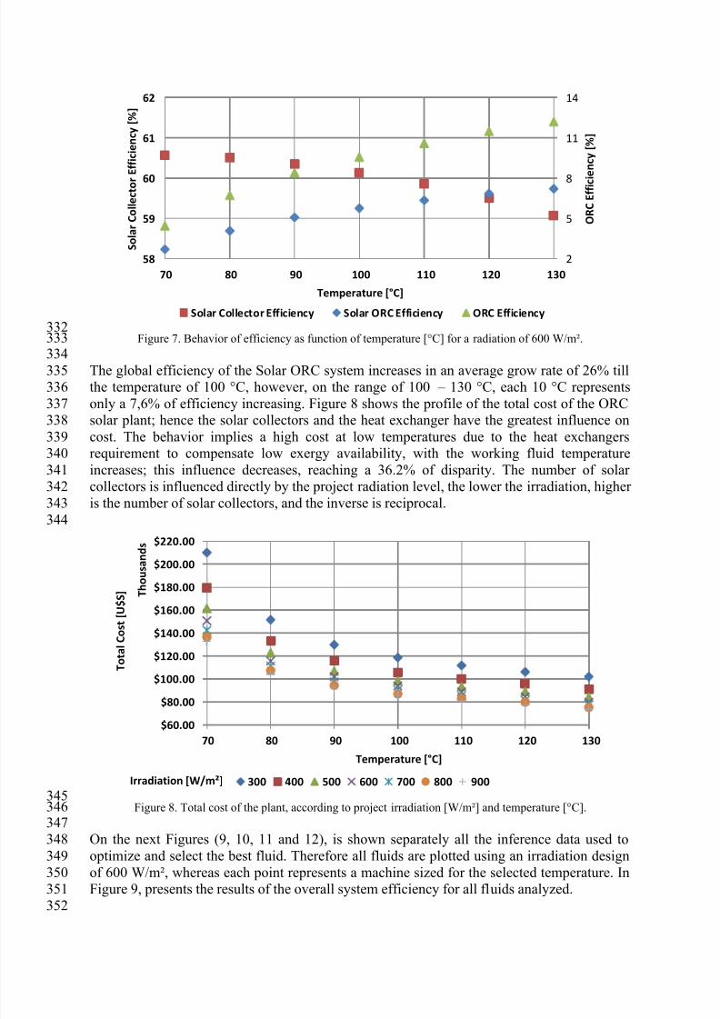
332Figure 7. Behavior of efficiency as function of temperature [°C] for a radiation of 600 W/m².333
334 The global efficiency of the Solar ORC system increases in an average grow rate of 26% till335the temperature of 100 °C, however, on the range of 100 – 130 °C, each 10 °C represents336only a 7,6% of efficiency increasing. Figure 8 shows the profile of the total cost of the ORC337solar plant; hence the solar collectors and the heat exchanger have the greatest influence on338cost. The behavior implies a high cost at low temperatures due to the heat exchangers339requirement to compensate low exergy availability, with the working fluid temperature340increases; this influence decreases, reaching a 36.2% of disparity. The number of solar341collectors is influenced directly by the project radiation level, the lower the irradiation, higher342is the number of solar collectors, and the inverse is reciprocal.343
344
345Figure 8. Total cost of the plant, according to project irradiation [W/m²] and temperature [°C].346
347On the next Figures (9, 10, 11 and 12), is shown separately all the inference data used to348optimize and select the best fluid. Therefore all fluids are plotted using an irradiation design349of 600 W/m², whereas each point represents a machine sized for the selected temperature. In350
Figure 9, presents the results of the overall system efficiency for all fluids analyzed.351352
2
5
8
11
14
58
59
60
61
62
70 80 90 100 110 120 130
O R C E f f i c i e n c y [ % ]
S o l a r C o l l e c t o r
E f f i c i e n c y [ % ]
Temperature [°C]
Solar Collector Efficiency Solar ORC Efficiency ORC Efficiency
$60.00
$80.00
$100.00
$120.00
$140.00
$160.00
$180.00
$200.00
$220.00
70 80 90 100 110 120 130
T o t a l C o s t [ U $ S ] T
h o u s a n d s
Temperature [°C]
300 400 500 600 700 800 900Irradiation [W/m²]

7/25/2019 Performance evaluation of working fluids based on Fuzzy logic for Solar ORC
http://slidepdf.com/reader/full/performance-evaluation-of-working-fluids-based-on-fuzzy-logic-for-solar-orc 13/17
353Figure 9. Efficiency as a function of temperature [°C] for a radiation of 600 W/m².354
355The trend in Figure 9 is repeated for other levels of radiation. Can be inferred the most356efficient fluid for a given operating temperature range, being that these fluids are approaching357a trend line. The fluids that guarantee greater efficiency to the system are in order, according358to their respective operating temperatures: R-600a, R-600, R-245fa, R-245ca, R-601 and R-359601a. Also examined efficiency is the Carnot equivalent efficiency; actually the points360represent how close the real efficiency is from the ideal Carnot efficiency is. Exposed in361Figure 10, also presents the same fluid trend of behavior that is shown in curve of Figure 19,362
however, features a maximum ceiling, being less than 30%.363364
365Figure 10. Equivalent Carnot Cycle Efficiency in function of temperature [°C] for a radiation of 600 W/m².366
0
1
2
3
4
5
6
7
8
9
10
60 80 100 120 140 160
E f f i c i e n c y [ % ]
Temperature [°C]
R113
R245fa
R245ca
R365mfc
R601
R601a
R601b
R-600
R-600a
Hexane
Isohexane
Cyclohexane
Benzene
0
5
10
15
20
25
30
35
60 80 100 120 140 160
E q u i v a l e n t C a r n o t C y c l e E f f i c i e n c y [ % ]
Temperature [°C]
R113
R245fa
R245ca
R365mfc
R601
R601a
R601b
R-600
R-600a
Hexane
Isohexane
Cyclohexane
Benzene

7/25/2019 Performance evaluation of working fluids based on Fuzzy logic for Solar ORC
http://slidepdf.com/reader/full/performance-evaluation-of-working-fluids-based-on-fuzzy-logic-for-solar-orc 14/17
367In Figure 11 is shown the variation of net solar collector field area which tends to a minimal368area of 100 m²; in Figure 12 is presented the total cost of the plant. In both Figures, 11 and36912, the elevation of temperature of working fluid implies in lower demand of solar collector,370which also results in lower investments costs.371
372
373
Figure 11. Solar field area versus temperature [°C] for a radiation of 600 W/m².374375
376 Figure 12. The plant's cost as a function of temperature [°C] for a radiation of 600 W/m².377378
0
100
200
300
400
500
600
700
800
900
1000
60 80 100 120 140 160
N e t S o l a r C o l l e c t o r F i e l d A r e a [ m ² ]
Temperature [°C]
R113
R245fa
R245ca
R365mfc
R601
R601a
R601b
R-600
R-600a
Hexane
Isohexane
Cyclohexane
Benzene
60
100
140
180
220
260
60 80 100 120 140 160
O v e r a l l
C o s t [ U $ S ]
T h o u s a n d s
Temperature [°C]
R113
R245fa
R245ca
R365mfc
R601
R601a
R601b
R-600
R-600a
Hexane
Isohexane
Cyclohexane
Benzene

7/25/2019 Performance evaluation of working fluids based on Fuzzy logic for Solar ORC
http://slidepdf.com/reader/full/performance-evaluation-of-working-fluids-based-on-fuzzy-logic-for-solar-orc 15/17
Applying fuzzy logic (equations 15 up to 19), using the results exposed in figures 9, 10, 11379and 12 is possible to evaluate which are the fluids with the best cost-effective performance380for the operational temperature range of the system. Figure 13 represents the end of the381second stage of the logic (before defuzzyfication) whose "1" represented in dark green382indicates convergence of the best criteria for such project, while the closer to zero, the383
gradient modifies to yellow and then white, representing the least equipment indicated, in384 addition there are two methodologies of interpretation:3851. Select the operating temperature of the system, then it is evaluating the highest value,386
in the same row, select the working fluid for best performance;3872. From a working fluid find out which working temperature the fluid receives the best388
score, thus allowing selecting the best operating conditions.389390
391Figure 13. Best working fluid as a function of the operating temperature.392
393This means, the most indicated working fluid for the temperature range of 60-70 °C is the R-394600a; for 80 °C is the R-600; for 90-120 °C is the R-245fa; for 130 °C R-245ca; and for 140-395
160 °C is the R-601. Consequently whereas “1”, means that the sized machine has the best396values inferred among the others sized machines with different fluid for same temperature397range. A value of “0.96” means that the system has 96% of agreement, and so on . This398means for example, for a 120 °C, the ranking of the most indicated fluids are R-245fa, R601,399R-245ca, etc. however none of them match’s 100%. 400
401Therefore among the select working fluids, there are three fluids which are more cost-402effective: R-600a, R-245fa, R-601 covering all temperature range. However only the R-245fa403has the highest scores and does so covers 64% of the temperature range.404
405Conclusion406In this work focused on the evaluation of working fluid for low temperature based on fuzzy407logic. Therefore a semi-empirical model was adopted; capable of sizing a 5 kWe solar ORC408system, using a parabolic cylinder technology, based on commercial and available409equipment’s for any dry-expansion working fluids. Each machine is sized to fit optimality for410each of 13 different working fluids; whereas are compared and analyzed under the same411given condition.412
413The fact that the system depend on a nominal irradiation affects extremely the number of414solar collectors. The ORC module performance depends on the organic fluid, operational415temperature and power usage, not suffering changes as a function of nominal irradiation,416
concluding that the systems when installed in areas of higher incidence have a lower specific417 installation cost which leads to a more competitive production energy cost.418

7/25/2019 Performance evaluation of working fluids based on Fuzzy logic for Solar ORC
http://slidepdf.com/reader/full/performance-evaluation-of-working-fluids-based-on-fuzzy-logic-for-solar-orc 16/17
419Due to the use of organic fluids the system is linked to its thermal performance, therefore420such behavior implies, that these results are also valid for different heat sources for the same421temperature range. Also suggests temperature boundaries to obtain the best performance and422optimization among the pre-selected fluids.423
424 The comparison between working fluids showed that the most cost-effective for low425temperature operation is R-245fa. However, to be able to cover integrally the temperature426range (60-160 °C) with higher efficiency, is more suitable to use three different working427fluids R-600a, R-245fa and R-601.428
429Acknowledgements430The authors want to thank to CAPES, CNPq, FAPEMIG, ANEEL, CEMIG and CPFL for431their collaboration and financial support in the development of this work.432
433References434[1] ALVES, M. S.; LORA, E.; PALACIO, J., (2012). Sizing and parametric study of a435
10kWel Solar Organic Rankine Cycle for Brazilian conditions. VII National Congress436of Mechanical Engineering437
[2] RODRÍGUEZ, C. E. C. ; Palacios ; Venturini ; LORA, Electo Eduardo Silva ; COBAS,438Vladimir Melián ; SANTOS, D. M. ; DOTTO, F. R. L. ; GIALLUCA, V. . Exergetic439and economic comparison of ORC and Kalina cycle for low temperature enhanced440geothermal system in Brazil. Applied Thermal Engineering , v. 52, p. 109-119, 2013.441
[3] DRESCHER, U., & BRÜGGEMANN, D. (2007). Fluid selection for the Organic442Rankine Cycle (ORC) in biomass power and heat plants. Applied Thermal Engineering ,44327 (1), 223 – 228. doi:10.1016/j.applthermaleng.2006.04.024444
[4] QUOILIN, S., LEMORT, V., & LEBRUN, J. (2010). Experimental study and modeling445 of an Organic Rankine Cycle using scroll expander. Applied Energy, 87 (4), 1260 – 1268.446doi:10.1016/j.apenergy.2009.06.026447
[5] QUOILIN, S., BROEK, M., DECLAYE, S., DEWALLEF, P., & LEMORT, V. (2013).448Techno-economic survey of Organic Rankine Cycle (ORC) systems. Renewable and449Sustainable Energy Reviews, 22, 168 – 186. doi:10.1016/j.rser.2013.01.028450
[6] ESPINOSA, N., TILMAN, L., LEMORT, V., QUOILIN, S., & LOMBARD, B. (2010).451Rankine cycle for waste heat recovery on commercial trucks: approach, constraints and452modelling, 1 – 10. Retrieved from http://orbi.ulg.ac.be/handle/2268/62995453
[7] QIU, G., SHAO, Y., LI, J., LIU, H., & RIFFAT, S. . B. (2012). Experimental454investigation of a biomass-fired ORC-based micro-CHP for domestic applications. Fuel ,455
96 , 374 – 382. doi:10.1016/j.fuel.2012.01.028456 [8] QUOILIN, S. (2011). Sustainable Energy Conversion Through the Use of Organic457 Rankine Cycles for Waste Heat Recovery and Solar Applications. University of Liège.458
[9] JING, L., GANG, P., & JIE, J. (2010). Optimization of low temperature solar thermal459electric generation with Organic Rankine Cycle in different areas. Applied Energy,46087 (11), 3355 – 3365. doi:10.1016/j.apenergy.2010.05.013461
[10] QUOILIN, S., DECLAYE, S., & LEMORT, V. (2010). Expansion machine and fluid462selection for the Organic rankine cycle. … Conference on Heat Transfer, Fluid …,463(July). Retrieved from http://orbi.ulg.ac.be/handle/2268/62997464
[11] VANKEIRSBILCK, I., & VANSLAMBROUCK, B. (2011). Organic Rankine Cycle as465efficient alternative to steam cycle for small scale power generation. Proceedings of466the …, (July). Retrieved from http://www.orcycle.eu/publicaties_bestanden/HEFAT4672011 - ORC vs steam_final.pdf468

7/25/2019 Performance evaluation of working fluids based on Fuzzy logic for Solar ORC
http://slidepdf.com/reader/full/performance-evaluation-of-working-fluids-based-on-fuzzy-logic-for-solar-orc 17/17
[12] KELLY, B., & KEARNEY, D. (2006). Parabolic Trough Solar System Piping Model469 Final Report Parabolic Trough Solar System Piping Model Final Report .470
[13] KAKAÇ, S., PRAMUANJAROENKIJ, A., & LIU, H. (2002). Heat exchangers:471 selection, rating, and thermal design.472
[14] GUT, J. A. W., & PINTO, J. M. (2003). Modeling of plate heat exchangers with473
generalized configurations. International Journal of Heat and Mass Transfer , 46 (14),474 2571 – 2585. doi:10.1016/S0017-9310(03)00040-1475[15] DAI, Y., WANG, J., & GAO, L. (2009). Parametric optimization and comparative476
study of organic Rankine cycle ( ORC ) for low grade waste heat recovery. Energy477Conversion and Management , 50(3), 576 – 582. doi:10.1016/j.enconman.2008.10.018478
[16] EARL COX; (1994) The Fuzzy Systems Handbook : a Practitioner's Guide to Building,479Using and Maintaining Fuzzy Systems; Professional, 1994 ; ISBN 0-12-194270-8480
[17] PEDRYCZ, W.; GOMIDE, F.; (2007), Fuzzy Systems Engineering : Toward Human-481Centric Computing; Wiley/IEEE Press, 2007 ; ISBN 978-0-471-78857-7482
[18] ALVES, M. S. (2013), Computational Modeling and Optimization of a Solar Organic483 Rankine Cycle with Parabolic Trough Collector, Itajubá - MG, 195 p. Dissertation484
(Master sciences in Energy Conversion) – Institute of Mechanical Engineering, Federal485University of Itajubá.486
Recommended