VB HYDRAULIC BRAKE VALVES
VB HYDRAULIC BRAKE VALVES2
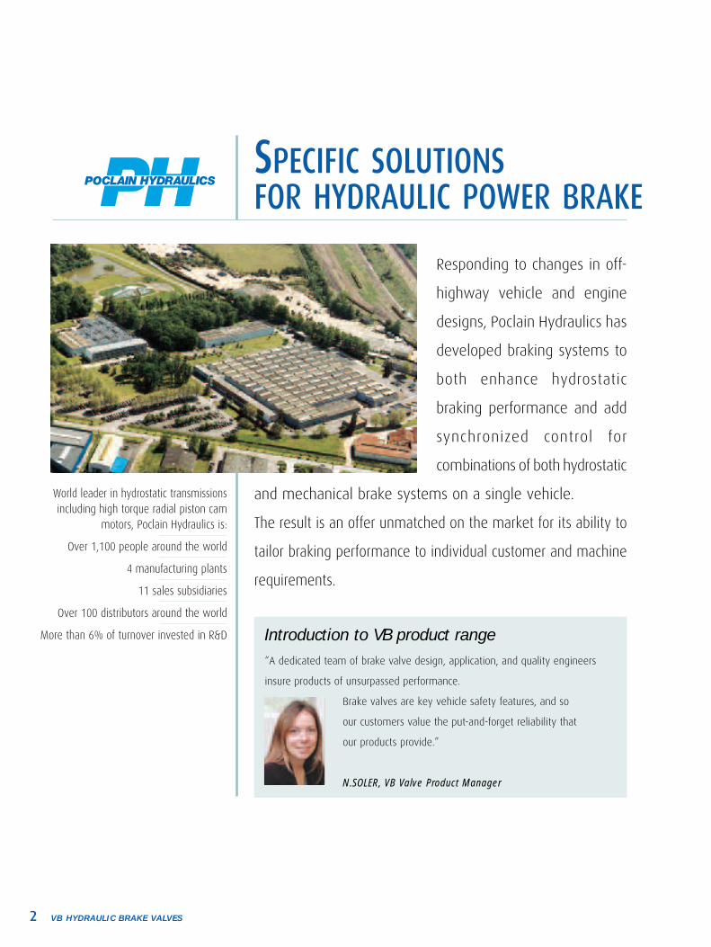
“A dedicated team of brake valve design, application, and quality engineers
insure products of unsurpassed performance.
Brake valves are key vehicle safety features, and so
our customers value the put-and-forget reliability that
our products provide.”
N.SOLER, VB Valve Product Manager
Introduction to VB product range
SPECIFIC SOLUTIONSFOR HYDRAULIC POWER BRAKE
World leader in hydrostatic transmissions including high torque radial piston cam
motors, Poclain Hydraulics is:
Over 1,100 people around the world
4 manufacturing plants
11 sales subsidiaries
Over 100 distributors around the world
More than 6% of turnover invested in R&D
Responding to changes in off-
highway vehicle and engine
designs, Poclain Hydraulics has
developed braking systems to
both enhance hydrostatic
braking performance and add
synchronized control for
combinations of both hydrostatic
and mechanical brake systems on a single vehicle.
The result is an offer unmatched on the market for its ability to
tailor braking performance to individual customer and machine
requirements.

3VB HYDRAULIC BRAKE VALVES
TABLE OF CONTENTS
• Options . . . . . . . . . . . . . . . . . . . . . . . . . . . . . . . . . . . . . . . . . . . . . . . . . . . . . . . . . 17
• Service . . . . . . . . . . . . . . . . . . . . . . . . . . . . . . . . . . . . . . . . . . . . . . . . . . . . . . . . . 18
• Technical Datasheet . . . . . . . . . . . . . . . . . . . . . . . . . . . . . . . . . . . . . . . . . . . . . . 19
• VB010 Single-circuit modulating brake valves . . . . . . . . . . . . . . . . . . . . . . . . . . . 6
• VB020, VB0E0, VB0F0 Dual-circuit modulating brake valves . . . . . . . . . . . . . . . 7
• VB0B0 Steering-assist brake valves . . . . . . . . . . . . . . . . . . . . . . . . . . . . . . . . . . . 8
• VB002 Reverse modulating brake valves . . . . . . . . . . . . . . . . . . . . . . . . . . . . . . . 9
• VB012 Single-circuit combined-brake valves . . . . . . . . . . . . . . . . . . . . . . . . . . . . 10
• VB022 Dual-circuit combined-brake valves . . . . . . . . . . . . . . . . . . . . . . . . . . . . . . 11
BBrraakkee aaccttuuaattoorrss
• VB100 Single-circuit accumulator charging valves . . . . . . . . . . . . . . . . . . . . . . . . 12
• VB200 Dual-circuit accumulator charging valves . . . . . . . . . . . . . . . . . . . . . . . . . 13
AAccccuummuullaattoorr cchhaarrggiinngg vvaallvveess
• VS Relay valves . . . . . . . . . . . . . . . . . . . . . . . . . . . . . . . . . . . . . . . . . . . . . . . . . . . 16
• VS Quick return valves . . . . . . . . . . . . . . . . . . . . . . . . . . . . . . . . . . . . . . . . . . . . . . 16
SSppeecciiaall vvaallvveess
• VB110 Single-circuit power brake valves . . . . . . . . . . . . . . . . . . . . . . . . . . . . . . 14
• VB220, VB2E0, VB2F0, VB22E Dual-circuit power brake valves . . . . . . . . . . . . 15
PPoowweerr bbrraakkee vvaallvveess
• Applications . . . . . . . . . . . . . . . . . . . . . . . . . . . . . . . . . . . . . . . . . . . . . . . . . . . . . 4
• Hydraulic brake systems . . . . . . . . . . . . . . . . . . . . . . . . . . . . . . . . . . . . . . . . . . 5
5VB HYDRAULIC BRAKE VALVES
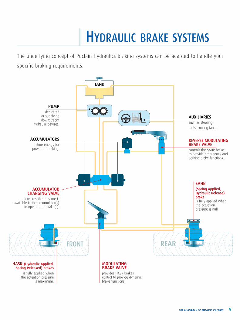
HYDRAULIC BRAKE SYSTEMSThe underlying concept of Poclain Hydraulics braking systems can be adapted to handle your
specific braking requirements.
PUMPdedicated
or supplying downstream
hydraulic devises.
AUXILIARIESsuch as steering,
tools, cooling fan…
REVERSE MODULATINGBRAKE VALVEcontrols the SAHR brake to provide emergency and parking brake functions.
MODULATING BRAKE VALVE provides HASR brakes control to provide dynamicbrake functions.
HASR (Hydraulic Applied, Spring Released) brakes
is fully applied when the actuation pressure
is maximum.
SAHR(Spring Applied, Hydraulic Release)brakeis fully applied whenthe actuation pressure is null.
ACCUMULATOR CHARGING VALVE
ensures the pressure is available in the accumulator(s)
to operate the brake(s).
ACCUMULATORS store energy for
power off braking.
TANK
FRONT REAR

VB HYDRAULIC BRAKE VALVES BRAKE ACTUATORS6
SSiinnggllee--cciirrccuuiitt mmoodduullaattiinngg bbrraakkee vvaallvveessVB010Description
• Mechanically operated modulating brake valves for brake actuation• Supplies one output pressure• Used with a single-circuit accumulator charging valve (VB100 for example)
Principle of operation
The VB010 supplies an operating pressure to the service brake(s) proportionalto the pedal position: the pressure from the valve to the brake(s) increases,from zero when the pedal is released, to a preset pressure, as the pedal is fullydepressed.
Characteristics
Pedal Stroke/angle
Pedal Stroke/angleBrake operating pressure
Brake operating pressure
Output Pressure
Output Pressure
BRAKE ACTUATORS
Maximum operating pressure
Output pressures
Mass (valve only)
Operating temperature
Fluid
a x b x c
210300020 fi 120 290 fi 1740 1.32.87-20 fi +120 -4 fi +248
50 x 35 x 97.51.97 x 1.37 x 3.84
barpsibarPSIkglbs°C°F
10µm filtered mineral oil
mminch
Features• 1 adjustable output pressure for service brake• Precise, modulated braking pressure • Small, lightweight package
c
ba
7VB HYDRAULIC BRAKE VALVES BRAKE ACTUATORS
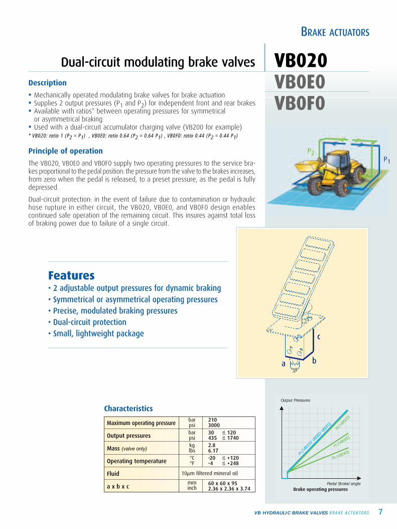
DDuuaall--cciirrccuuiitt mmoodduullaattiinngg bbrraakkee vvaallvveess VB020VB0E0VB0F0
Description
• Mechanically operated modulating brake valves for brake actuation • Supplies 2 output pressures (P1 and P2) for independent front and rear brakes• Available with ratios* between operating pressures for symmetrical
or asymmetrical braking • Used with a dual-circuit accumulator charging valve (VB200 for example)* VB020: ratio 1 (P2 = P1) , VB0E0: ratio 0.64 (P2 = 0.64 P1) , VB0F0: ratio 0.44 (P2 = 0.44 P1)
Principle of operation
The VB020, VB0E0 and VB0F0 supply two operating pressures to the service bra-kes proportional to the pedal position: the pressure from the valve to the brakes increases,from zero when the pedal is released, to a preset pressure, as the pedal is fullydepressed.
Dual-circuit protection: in the event of failure due to contamination or hydraulichose rupture in either circuit, the VB020, VB0E0, and VB0F0 design enablescontinued safe operation of the remaining circuit. This insures against total lossof braking power due to failure of a single circuit.
Pedal Stroke/angle
Pedal Stroke/angleBrake operating pressure
Brake operating pressures
Output Pressure
Output Pressures
P1 (VB0
20/V
B0E0
/VB0
F0)
P2 (VB0
20)
P2 (VB0E0)
P2 (VB0F0)
BRAKE ACTUATORS
Characteristics
Maximum operating pressure
Output pressures
Mass (valve only)
Operating temperature
Fluid
a x b x c
210300030 fi 120 435 fi 1740 2.86.17-20 fi +120 -4 fi +248
60 x 60 x 952.36 x 2.36 x 3.74
barpsibarpsikglbs°C°F
10µm filtered mineral oil
mminch
Features• 2 adjustable output pressures for dynamic braking• Symmetrical or asymmetrical operating pressures• Precise, modulated braking pressures• Dual-circuit protection • Small, lightweight package c
ba
P2P1

SSiinnggllee--cciirrccuuiitt sstteeeerriinngg--aassssiisstt bbrraakkee vvaallvveessVB0B0
VB HYDRAULIC BRAKE VALVES BRAKE ACTUATORS8
Description
• Mechanically operated modulating brake valves for steering assist and service braking
• Supplies 2 identical output pressures (P1 and P2)• Used with a single-circuit accumulator charging valve (VB100 for example)
Principle of operation
VB0B0 actuation is accomplished using two pedals: the right pedal controls themachine right-hand brakes, and the left pedal the machine left-hand brakes.
• Work mode (Directional braking right/left)In work mode both pedals are actuated independently. When the operator depres-ses either of the two pedals, the VB0B0 supplies precise operating pressure exclusivelyto the service brake associated to this pedal.
• Road mode (Braking with equal power distribution)In road mode the two pedals are mechanically linked together: when the ope-rator depresses either of the two pedals, the VB0B0 supplies precise and strictlyidentical operating pressure to the service brakes of both sides of the machine.
Characteristics
Pedal Stroke/angleBrake operating pressures
Output Pressures
P2
P1
Maximum operating pressure
Output pressures
Mass (valve only)
Operating temperature
Fluid
a x b x c
210300020 fi 120 290 fi 1740 6.514.33-20 fi +120 -4 fi +248
60 x 135 x 952.36 x 5.31 x 3.74
barpsibarpsikglbs°C°F
10µm filtered mineral oil
mminch
Features• 2 identical, adjustable output pressures• Steering-assist / service braking function• Precise, modulated output pressures • Small, lightweight package
BRAKE ACTUATORS
c
ba
P1P2
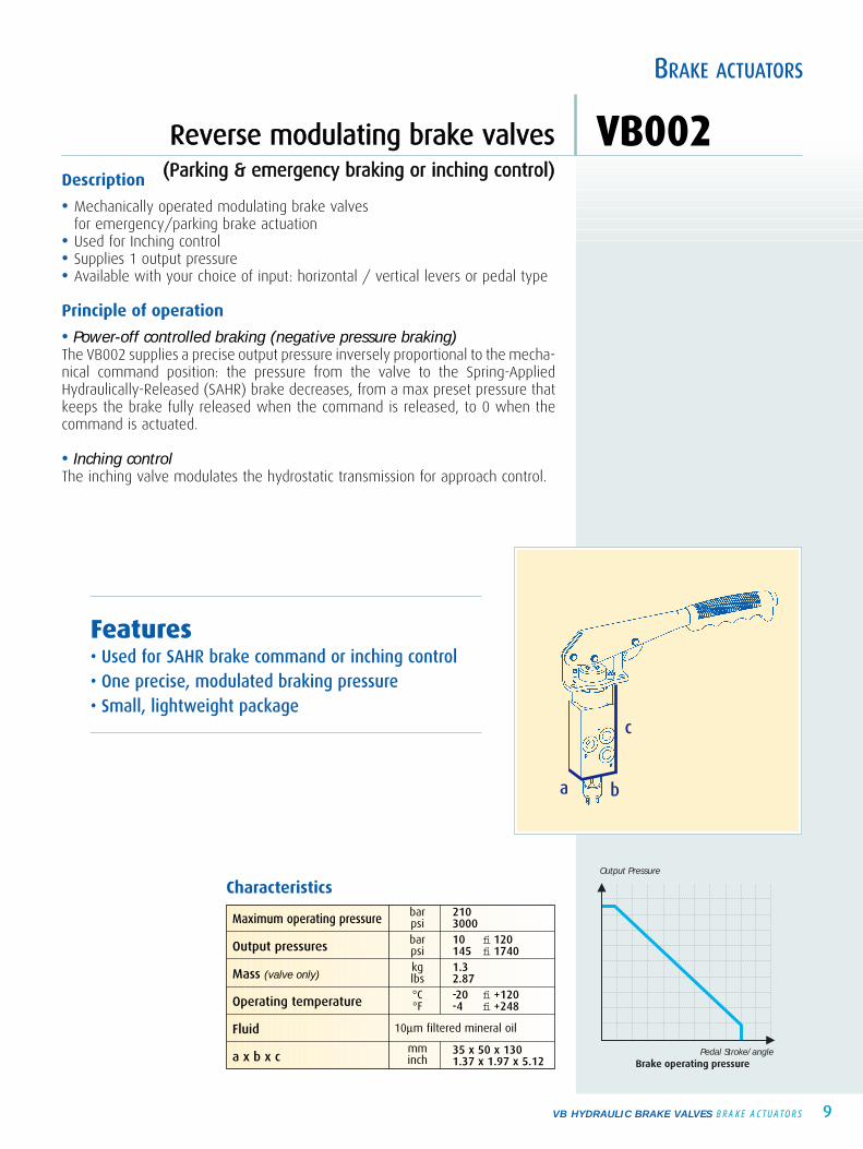
RReevveerrssee mmoodduullaattiinngg bbrraakkee vvaallvveess ((PPaarrkkiinngg && eemmeerrggeennccyy bbrraakkiinngg oorr iinncchhiinngg ccoonnttrrooll))
VB002
BRAKE ACTUATORS
9VB HYDRAULIC BRAKE VALVES BRAKE ACTUATORS
Description
• Mechanically operated modulating brake valves for emergency/parking brake actuation
• Used for Inching control• Supplies 1 output pressure• Available with your choice of input: horizontal / vertical levers or pedal type
Principle of operation
• Power-off controlled braking (negative pressure braking)The VB002 supplies a precise output pressure inversely proportional to the mecha-nical command position: the pressure from the valve to the Spring-AppliedHydraulically-Released (SAHR) brake decreases, from a max preset pressure thatkeeps the brake fully released when the command is released, to 0 when thecommand is actuated.
• Inching controlThe inching valve modulates the hydrostatic transmission for approach control.
Pedal Stroke/angleBrake operating pressure
Output Pressure
Characteristics
Features• Used for SAHR brake command or inching control• One precise, modulated braking pressure• Small, lightweight package
Maximum operating pressure
Output pressures
Mass (valve only)
Operating temperature
Fluid
a x b x c
210300010 fi 120 145 fi 1740 1.32.87-20 fi +120 -4 fi +248
35 x 50 x 1301.37 x 1.97 x 5.12
barpsibarpsikglbs°C°F
10µm filtered mineral oil
mminch
c
ba

SSiinnggllee--cciirrccuuiitt ccoommbbiinneedd--bbrraakkee vvaallvveessVB012
BRAKE ACTUATORS
VB HYDRAULIC BRAKE VALVES BRAKE ACTUATORS10
Description
• Mechanically operated modulating brake valves for braking combinations: consecutive or simultaneous hydrostatic and service braking
• Supplies 1 output pressure for service braking• Supplies 1 output pressure for pump control• Used with a single-circuit accumulator charging valve (VB100 for example)
Principle of operation
• 2-step brakingInitial portion of the pedal stroke: the VB012 supplies a precise output pressureinversely proportional to the pedal position to control the hydraulic pump.
If the braking is not sufficient, the operator continues to push on the pedal.
The last portion of pedal stroke, the VB012 supplies an operating pressure to theservice brakes proportional to the pedal position to control the service brakes.
• Simultaneous brakingThe VB012 is able to synchronize the operation of both hydraulic pump control(hydrostatic braking) and service brakes (mechanical braking) simultaneously.
Characteristics
Pedal Stroke/angle Pedal Stroke/angle
Output Pressures
Brak
e co
ntro
l
Pump control
Output Pressures
Brake operating pressures Brake operating pressures
Brak
e co
ntro
l
Pump control
Pedal Stroke/angle Pedal Stroke/angle
Output PressuresBr
ake
cont
rol
Pump control
Output Pressures
Brake operating pressures Brake operating pressures
Brak
e co
ntro
l
Pump control
Maximum operating pressure
Output pressures
Mass (valves only)
Operating temperature
Fluid
a x b x c
210300020 fi 120 290 fi 1740 2.65.73-20 fi +120 -4 fi +248
130 x 50 x 1285.11 x 1.97 x 5.03
barpsibarpsikglbs°C°F
10µm filtered mineral oil
mminch
Features• 1 output pressure for pump control• 1 output pressure for service brakes command• Precise, modulated braking pressures• Small, lightweight package
c
a
b

DDuuaall--cciirrccuuiitt ccoommbbiinneedd--bbrraakkee vvaallvveess VB022VB0E2VB0F2
BRAKE ACTUATORS
11VB HYDRAULIC BRAKE VALVES BRAKE ACTUATORS
Pedal Stroke/angle Pedal Stroke/angle
Output Pressures
Brak
e co
ntro
l
Pump control
Output Pressures
Brake operating pressures Brake operating pressures
Brak
e co
ntro
l
Pump control
VB022
P1 (
VB02
2/VB
0E2/
VB0F
2)
P2 (
VB02
2)
P2 (
VB0E
2)
P2 (V
B0F2
)
P1 (V
B022
/VB0
E2/V
B0F2
) P2
(VB0
22)
P2 (VB0E2)
P2 (VB0F2)
Pedal Stroke/angle Pedal Stroke/angle
Output PressuresBr
ake
cont
rol
Pump control
Output Pressures
Brake operating pressures Brake operating pressures
Brak
e co
ntro
l
Pump control
VB022
P1 (
VB02
2/VB
0E2/
VB0F
2)
P2 (
VB02
2)
P2 (
VB0E
2)
P2 (V
B0F2
)
P1 (V
B022
/VB0
E2/V
B0F2
) P2
(VB0
22)
P2 (VB0E2)
P2 (VB0F2)
Description
• Mechanically operated modulating brake valves for braking combinations: consecutive or simultaneous hydrostatic and service braking
• Supplies 1 output pressure for pump control• Supplies 2 output pressures (P1 and P2) for independent front and rear brakes• Available with ratios* between operating pressures for symmetrical
or asymmetrical braking• Used with a dual-circuit accumulator charging valve (VB200 for example)* VB022: ratio 1 (P2 = P1) , VB0E2: ratio 0.64 (P2 = 0.64 P1) , VB0F2: ratio 0.44 (P2 = 0.44 P1)
Principle of operation
• 2-step brakingInitial portion of the pedal stroke: the valves supply a precise output pressureinversely proportional to the pedal position to control the hydraulic pump. If thebraking is not sufficient, the operator continues to push on the pedal.The last portion of pedal stroke, the valves supply 2 operating pressures to theservice brakes proportional to the pedal position to control the mechanical brake.
• Simultaneous brakingThe VB022 is able to synchronize the operation of both hydraulic pump control(hydrostatic braking) and service brakes (mechanical braking) simultaneously.
Dual-circuit protection: in the event of failure (contamination or hydraulic hose rup-ture) in either circuit, the VB022, VB0E2 and VB0F2 design enables continued safeoperation of the remaining circuit. This insures against total loss of braking powerdue to failure of a single circuit.
Features• 1 output pressure for pump control• 2 output pressures for dynamic brake command• Symmetric or dissymmetric pressure outputs• Dual-circuit protection • Precise, modulated braking pressures• Small, lightweight package
Characteristics
Maximum operating pressure
Output pressures
Mass (valves only)
Operating temperature
Fluid
a x b x c
210300030 fi 120 435 fi 1740 4.19.03-20 fi +120 -4 fi +248
60 x 128 x 1462.36 x 5.11 x 5.70
barpsibarpsikglbs°C°F
10µm filtered mineral oil
mminch
c
b a

SSiinnggllee--cciirrccuuiitt aaccccuummuullaattoorr cchhaarrggiinngg vvaallvveessVB100
VB HYDRAULIC BRAKE VALVES ACCUMULATOR CHARGING VALVES12
Description
• Supplies 1 output to keep the accumulator under pressure• Supplies 1 output for auxiliaries• Used with single-circuit modulating brake valves
Principle of operation
Hydraulic energy is stored by maintaining pressure in the accumulator within apreset range (cut-in and cut-out pressures).
When accumulator pressure reaches its lower limit (cut-in pressure), a small amountof oil is diverted from the auxiliaries to recharge the accumulator.
Once the accumulator pressure reaches the upper limit (cut-out pressure),the valve automatically stops charging the accumulator and resumes fullflow to auxiliaries
ACCUMULATOR CHARGING VALVES
high limit
low limit
Time
Output pressure
Pressure in the accumulator
recharge
"x" braking
Features• 1 output to the accumulator• 1 output for auxiliaries • Load sensing option available• Small, lightweight package
Characteristics
Maximum operating pressure
Cut-in/cut-out pressures
Flow rate to accumulator
Flow rate to auxiliaries
Mass (valve only)
Operating temperature
Fluid
a x b x c
barpsibarpsibarpsi
l/minUS gpml/min
US gpmkglbs°C°F
10µm filtered mineral oil
mminch
2103000110/130 120/140 135/1601600/1900 1740/2030 1950/2320160/190 170/200 180/2102320/2750 2460/2900 2600/30002.75, 8, 150.75, 2.1, 4.030, 45, 1208, 12, 322.24.8-20 fi +120 -4 fi +248
70 x 61 x 95 70 x 70 x 952,75 x 2,40 x 3,74 2,75 x 2,75 x 3,74
c
ba
30 & 45* 120*
* Flow rate to auxiliaries (l/min)

DDuuaall--cciirrccuuiitt aaccccuummuullaattoorr cchhaarrggiinngg vvaallvveess VB200
ACCUMULATOR CHARGING VALVES
13VB HYDRAULIC BRAKE VALVES ACCUMULATOR CHARGING VALVES
Description
• Supplies 2 outputs to keeps the accumulators under pressure• Supplies 1 output for auxiliaries• Used with dual-circuit modulating brake valves
Principle of operation
Hydraulic energy is stored by maintaining pressure in the accumulators within apreset range (cut-in and cut-out pressures).
When accumulator pressure reaches its lower limit (cut-in pressure), a small amountof oil is diverted from the auxiliaries to recharge the accumulators.
Once the accumulator pressure reaches the upper limit (cut-out pres-sure), the valve automatically stops charging the accumulators and resumesfull flow to auxiliaries.
Fail-safe design: The VB200 design includes an inverted shuttle valveto isolate the accumulators for two independent brake circuits (sepa-rate brake circuits for front and rear brakes).
high limit
low limit
Time
Output pressures
Pressure in the accumulators
recharge
"x" braking
Features• 2 outputs to accumulators• 1 output for auxiliaries• Load sensing option available• Dual-circuit protection• Small, lightweight package
c
ba
Characteristics
Maximum operating pressure
Cut-in/cut-out pressures
Flow rate to accumulator
Flow rate to auxiliaries
Mass (valve only)
Operating temperature
Fluid
a x b x c
barpsibarpsibarpsi
l/minUS gpml/min
US gpmkglbs°C°F
10µm filtered mineral oil
mminch
2103000110/130 120/140 135/1601600/1900 1740/2030 1950/2320160/190 170/200 180/2102320/2750 2460/2900 2600/30002.75, 8, 150.75, 2.1, 4.030, 45, 1208, 12, 3248.8-20 fi +120 -4 fi +248
61 x 87 x 95 70 x 87 x 952.40 x 3.42 x 3.74 2.75 x 3.42 x 3.74
30 & 45* 120*
* Flow rate to auxiliaries (l/min)
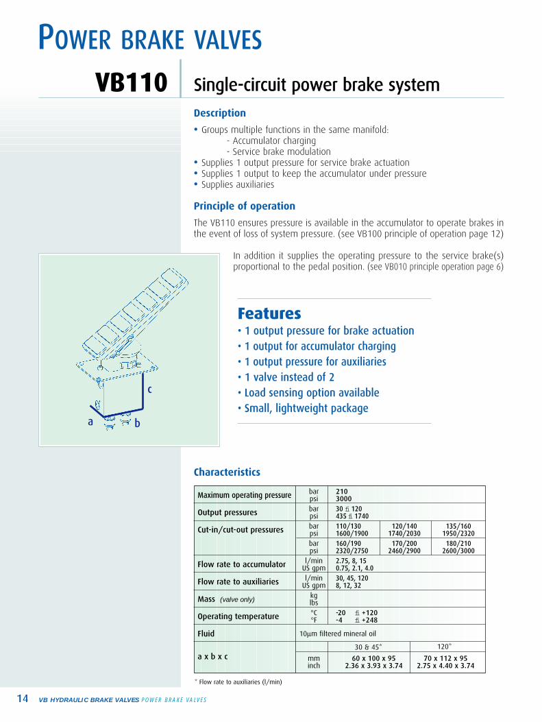
SSiinnggllee--cciirrccuuiitt ppoowweerr bbrraakkee ssyysstteemmVB110
VB HYDRAULIC BRAKE VALVES POWER BRAKE VALVES14
Description
• Groups multiple functions in the same manifold: - Accumulator charging - Service brake modulation
• Supplies 1 output pressure for service brake actuation• Supplies 1 output to keep the accumulator under pressure• Supplies auxiliaries
Principle of operation
The VB110 ensures pressure is available in the accumulator to operate brakes inthe event of loss of system pressure. (see VB100 principle of operation page 12)
In addition it supplies the operating pressure to the service brake(s)proportional to the pedal position. (see VB010 principle operation page 6)
POWER BRAKE VALVES
Features• 1 output pressure for brake actuation• 1 output for accumulator charging• 1 output pressure for auxiliaries• 1 valve instead of 2• Load sensing option available• Small, lightweight package
Characteristics
Maximum operating pressure
Output pressures
Cut-in/cut-out pressures
Flow rate to accumulator
Flow rate to auxiliaries
Mass (valve only)
Operating temperature
Fluid
a x b x c
barpsibarpsibarpsibarpsi
l/minUS gpml/min
US gpmkglbs°C°F
10µm filtered mineral oil
mminch
210300030 fi 120435 fi 1740110/130 120/140 135/1601600/1900 1740/2030 1950/2320160/190 170/200 180/2102320/2750 2460/2900 2600/30002.75, 8, 150.75, 2.1, 4.030, 45, 1208, 12, 32
-20 fi +120 -4 fi +248
60 x 100 x 95 70 x 112 x 952.36 x 3.93 x 3.74 2.75 x 4.40 x 3.74
c
ba
* Flow rate to auxiliaries (l/min)
30 & 45* 120*

POWER BRAKE VALVES
15VB HYDRAULIC BRAKE VALVES POWER BRAKE VALVES
Description
• Groups multiple functions in the same manifold: - Accumulator charging - Service brake modulation- Parking brake electrical control (VB22E only)
• Supplies 2 output pressures (P1 and P2) for independent front and rear brakes• Available with ratios* between operating pressures for symmetrical
or asymmetrical braking• Supplies 2 outputs to keep the accumulators under pressure• Supplies 1 output for auxiliaries* VB220: ratio 1 (P2 = P1) , VB2E0: ratio 0.64 (P2 = 0.64 P1) , VB2F0: ratio 0.44 (P2 = 0.44 P1)
Principle of operation
The dual-circuit power brake systems ensure pressure is available in the accu-mulators to operate brakes in the event of loss of system pressure. (see VB200principle of operation page 13)
In addition it supplies the operating pressure to the service brakes proportio-nal to the pedal position. (see VB020/VB0E0/VB0F0 principle operation page 7)
Finally the VB22E supplies an on/off pressure for parking brake control.
Features• 2 output pressures for brake actuation• 2 outputs for accumulators charging• 1 output for auxiliaries• 1 valve instead of 2 or 3
DDuuaall--cciirrccuuiitt ppoowweerr bbrraakkee ssyysstteemmss VB220VB2E0VB2F0VB22E
Characteristics
Maximum operating pressure
Output pressures
Cut-in/cut-out pressures
Flow rate to accumulator
Flow rate to auxiliaries
Operating temperature
Fluid
a x b x c
barpsibarpsibarpsibarpsi
l/minUS gpml/min
US gpmkglbskglbs°C°F
10µm filtered mineral oil
mminch
210300030 fi 120435 fi 1740110/130 120/140 135/1601600/1900 1740/2030 1950/2320160/190 170/200 180/2102320/2750 2460/2900 2600/30002.75, 8, 150.75, 2.1, 4.030, 45, 1208, 12, 32613.22817.63-20 fi +120 -4 fi +248
60 x 100 x 95 70 x 112 x 95 60 x 173 x 1352.36 x 3.93 x 3.74 2.75 x 4.40 x 3.74 2.36 x 6.81 x 5.31
Mass(valve only)
VB220,VB2E0, VB2F0
VB22E
VB220 30 & 45* VB220 120* VB22E
* Flow rate to auxiliaries (l/min)
c
ba
cba
VB22E
VB220
• Load sensing option available• Small, lightweight package

VVSS RReellaayy vvaallvveess
SPECIAL VALVES
VB HYDRAULIC BRAKE VALVES SPECIAL VALVES16
VVSS vvaallvveess aarree ddeessiiggnneedd ffoorr aapppplliiccaattiioonnss wwiitthh vveerryy lloonngg bbrraakkee lliinneess oorr vveerryy llaarrggee bbrraakkeeccyylliinnddeerr vvoolluummee rreeqquuiirriinngg hhiigghh ffllooww ((7700ll//mmiinn -- 1188..55 UUSS ggppmm))..
Description
• External hydraulic pilot • Located between the accumulator(s) and the brake(s)• Controlled and used with a modulating brake valve
Principle of operation
Control pressure is supplied to the VS valve proportional to brakepedal angle. The VS relay valve provides, at high flow, pressurefrom the accumulators out to the brakes directly proportional tothe control pressure, i.e. directly proportional to the pedalposition. The braking is progressif.
VVSS QQuuiicckk RReettuurrnn vvaallvveess
Description
• Internal hydraulic pilot• Located between the Spring Applied Hydraulically Released
(SAHR) brake(s) and the tank• Controlled by and used with Poclain Hydraulics VB002
Principle of operation
Control pressure is supplied to the VS valve proportional to SAHRactuation. The VS quick return valve transfers the flow comingfrom the brakes to the tank directly proportional to the controlpressure, i.e. directly proportional to the SAHR actuation.The braking is progressif.
Features• Flow rate at 70l/min - 18.5 US gpm• Enhanced brake response time• Easily mounted near brakes,accumulators and tank
• Small, lightweight package
Characteristics
Maximum operating pressure
Ratio pilot pressurepressure/output
Flow rate
Mass
Operating temperature
Fluid
a x b x c
barpsi
l/minUS gpm
kglbs°C°F
10µm filtered mineral oil
mminch
2103000
1/1
7018.524.40-20 fi +120 -4 fi +248
60 x 35 x 1252.36 x 1.38 x 4.92
c
ba
c
ba
17VB HYDRAULIC BRAKE VALVES OPTIONS
VB VB VB VB VB VB VB VB VB VB VB VB VB002 010 012 0B0 020 0E0 022 100 110 200 220 2E0 22E
0F0 2F0
4
4
4 4 4 4 4 4 4 4 4 4
4 4 4 4 4 4 4 4
4 4 4 4 4 4 4 4
4 4 4 4 4 4
4 4 4 4 4 4 4 4 4 4
4 4 4 4 4 4
4 4 4 4
4 4 4 4
4 4 4 4 4 4
4 4 4 4 4 4 4 4 4 4
4 4 4 4 4 4 4
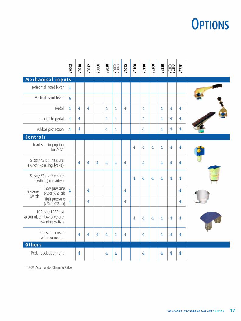
Horizontal hand lever
Vertical hand lever
Pedal
Lockable pedal
Rubber protection
Load sensing option for ACV*
5 bar/72 psi Pressureswitch (parking brake)
5 bar/72 psi Pressureswitch (auxilaries)
Pressureswitch
105 bar/1522 psiaccumulator low pressure
warning switch
Pressure sensor with connector
Pedal back abutment
Low pressure (<50bar/725 psi)High pressure(>50bar/725 psi)
Mechanical inputs
Controls
Others
VB00
2
VB01
0
VB01
2
VB0B
0
VB02
0
VB0E
0VB
0F0
VB02
2
VB10
0
VB11
0
VB20
0
VB22
0
VB2E
0VB
2F0
VB22
E
OPTIONS
* ACV: Accumulator Charging Valve
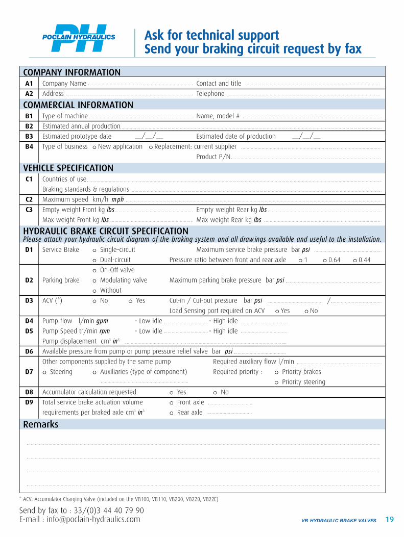
AAsskk ffoorr tteecchhnniiccaall ssuuppppoorrttSSeenndd yyoouurr bbrraakkiinngg cciirrccuuiitt rreeqquueesstt bbyy ffaaxx
19VB HYDRAULIC BRAKE VALVES
COMPANY INFORMATIONA1 Company Name Contact and title
A2 Address Telephone
COMMERCIAL INFORMATIONB1 Type of machine Name, model #
B2 Estimated annual production
B3 Estimated prototype date __/__/__ Estimated date of production __/__/__
B4 Type of business o New application o Replacement: current supplier
Product P/N
VEHICLE SPECIFICATIONC1 Countries of use
Braking standards & regulations
C2 Maximum speed km/h mph
C3 Empty weight Front kg lbs Empty weight Rear kg lbs
Max weight Front kg lbs Max weight Rear kg lbs
HYDRAULIC BRAKE CIRCUIT SPECIFICATIONPlease attach your hydraulic circuit diagram of the braking system and all drawings available and useful to the installation.D1 Service Brake o Single-circuit Maximum service brake pressure bar psi
o Dual-circuit Pressure ratio between front and rear axle o 1 o 0.64 o 0.44
o On-Off valve
D2 Parking brake o Modulating valve Maximum parking brake pressure bar psi
o Without
D3 ACV (*) o No o Yes Cut-in / Cut-out pressure bar psi /
Load Sensing port required on ACV o Yes o No
D4 Pump flow l/min gpm - Low idle - High idle
D5 Pump Speed tr/min rpm - Low idle - High idle
Pump displacement cm3 in3
D6 Available pressure from pump or pump pressure relief valve bar psi
Other components supplied by the same pump Required auxiliary flow l/min
D7 o Steering o Auxiliaries (type of component) Required priority : o Priority brakes
o Priority steering
D8 Accumulator calculation requested o Yes o No
D9 Total service brake actuation volume o Front axle
requirements per braked axle cm3 in3 o Rear axle
Remarks
* ACV: Accumulator Charging Valve (included on the VB100, VB110, VB200, VB220, VB22E)
Send by fax to : 33/(0)3 44 40 79 90E-mail : [email protected]
Recommended