Parametric Study of Contact Fritting for Improved CRes Stability
06/12/2006 – SWTW, San Diego
Dr. Christian Degen, Oliver Nagler, Michael Horn, Dr. Florian Kaesen
Infineon Technologies AG, GermanyCommunication Solutions – Test Techonolgy (COM TT)

C. Degen: Contact Fritting (SWTW 2006)
Page 2
??? Fritting ???Electrical conditioning of contacts by ‘overvoltage’ / ‘overcurrent’
••HolmHolm‘‘ss theory of electrictheory of electric contactscontacts
CanCan frittingfritting bebe utilizedutilized forfor contactcontact conditioning of probe needles?conditioning of probe needles?
••OverviewOverview overover evaluationevaluation setupsetup
PRPRobeobeFOFOrcerceIInvestigationnvestigationTTool (PROFIT)ool (PROFIT)
••Parameters underParameters under study:study:
••AA--fritting and Bfritting and B--frittingfritting
••CurrentCurrent level and polaritylevel and polarity
••propro‘‘s and cons and con‘‘s, conclusionss, conclusions
C. Degen: Contact Fritting (SWTW 2006)
Page 3
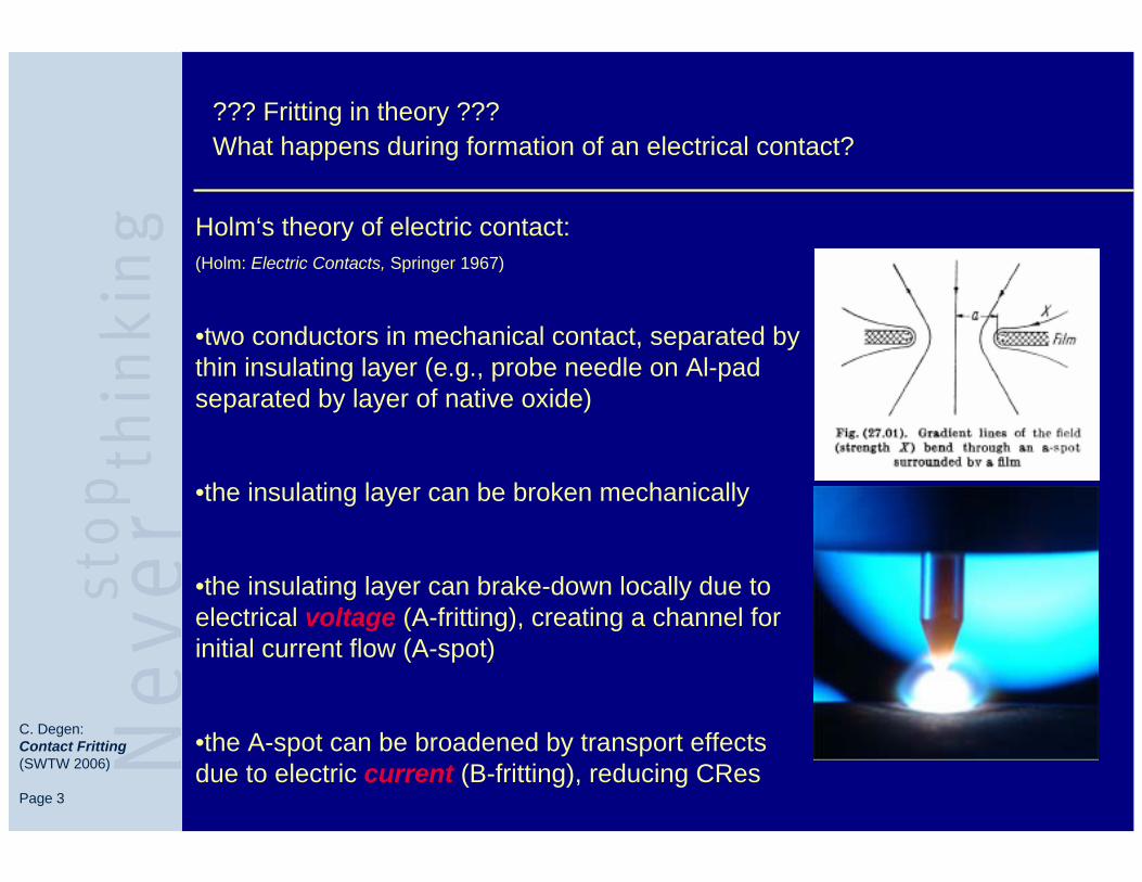
Holm‘s theory of electric contact:(Holm: Electric Contacts, Springer 1967)
•two conductors in mechanical contact, separated bythin insulating layer (e.g., probe needle on Al-padseparated by layer of native oxide)
•the insulating layer can be broken mechanically
•the insulating layer can brake-down locally due to electrical voltage (A-fritting), creating a channel forinitial current flow (A-spot)
•the A-spot can be broadened by transport effectsdue to electric current (B-fritting), reducing CRes
??? Fritting in theory ???What happens during formation of an electrical contact?
C. Degen: Contact Fritting (SWTW 2006)
Page 4
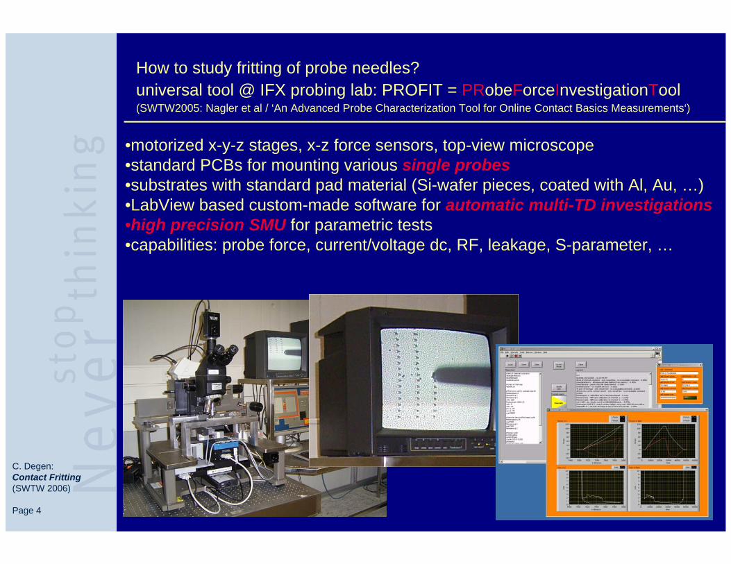
How to study fritting of probe needles? universal tool @ IFX probing lab: PROFIT = PRobeForceInvestigationTool(SWTW2005: Nagler et al / ‘An Advanced Probe Characterization Tool for Online Contact Basics Measurements‘)
•motorized x-y-z stages, x-z force sensors, top-view microscope•standard PCBs for mounting various single probes•substrates with standard pad material (Si-wafer pieces, coated with Al, Au, …)•LabView based custom-made software for automatic multi-TD investigations•high precision SMU for parametric tests •capabilities: probe force, current/voltage dc, RF, leakage, S-parameter, …

C. Degen: Contact Fritting (SWTW 2006)
Page 5
How stable is a probe contact?TungstenRhenium cantilever 20µm tip on Aluminum, OD=20µm, 1000TDs
024
68
101214
161820
CRes @ I=1mA
CRes @ I=10mA
0 200 400 600 800 1000024
68
101214
161820
CRes @ I=30mACR
es in
Ohm
s
number TDs
0 200 400 600 800 1000
CRes @ I=100mA
•CRes degrades after several 100 TDs without cleaning•probes accumulate Al-oxide -> isolating layer between tip and pad
C. Degen: Contact Fritting (SWTW 2006)
Page 6
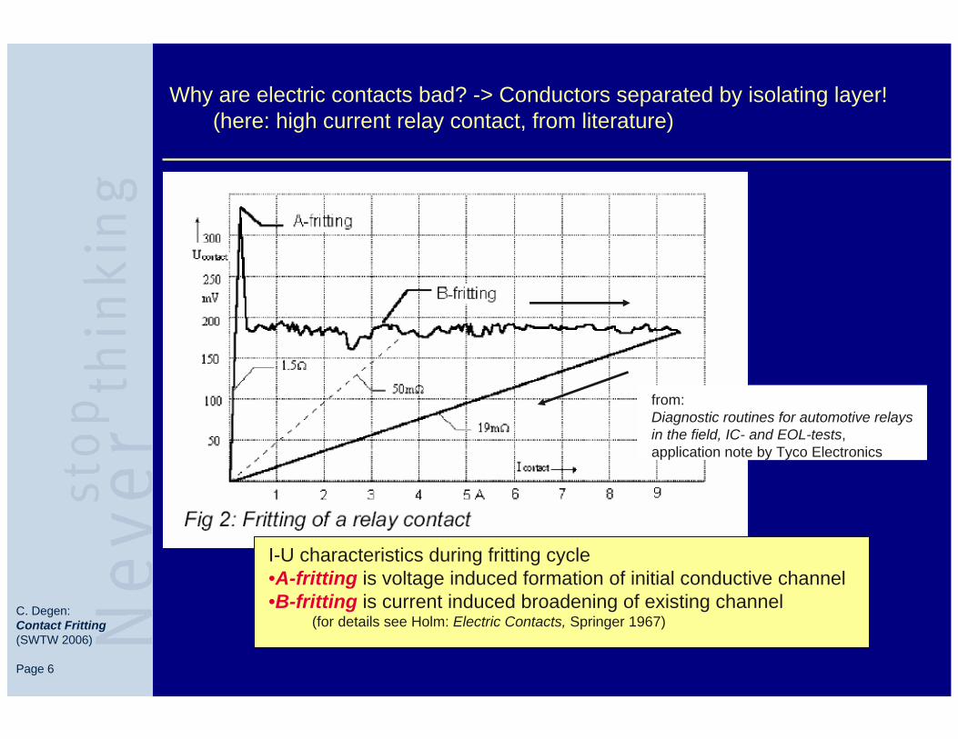
Why are electric contacts bad? -> Conductors separated by isolating layer!(here: high current relay contact, from literature)
from: Diagnostic routines for automotive relays in the field, IC- and EOL-tests, application note by Tyco Electronics
I-U characteristics during fritting cycle•A-fritting is voltage induced formation of initial conductive channel•B-fritting is current induced broadening of existing channel
(for details see Holm: Electric Contacts, Springer 1967)

C. Degen: Contact Fritting (SWTW 2006)
Page 7
0 -20m -40m -60m -80m -100m0.00
-0.05
-0.10
-0.15
-0.20
-0.25
-0.30
-0.35
-0.40
2.8Ohms
18Ohms
sens
e vo
ltage
in V
olts
drive current in Amps
0.0 -20.0m -40.0m -60.0m -80.0m -100.0m0.0
-0.1
-0.2
-0.3
-0.4
-0.5
contact overdrive
volta
ge in
Vol
ts
current in Amps
A-fritting
B-fritting
Formation of electric contact: cantilever TD on Aluminum pad(high precision quasistatic measurement / full trace ~1sec)
•observation of A-fritting and B-fritting for probe needles on pad material

C. Degen: Contact Fritting (SWTW 2006)
Page 8
0
10
20
30
40
50
60
70
0.0E+00 1.0E-04 2.0E-04 3.0E-04 4.0E-04 5.0E-04time in seconds
CR
es in
Ohm
s
0.00
0.02
0.04
0.06
0.08
0.10
0.12
0.14
0.16
curr
ent i
n A
mps
CRes during frittingCRes after frittingcurrent ramp
What are the typical timescales for contact fritting?-> investigation of voltage drop across contact during current step
•current step <50µs•full breakdown of insulating layer after ~150µs (typ. <<1msec)•instantaneously low CRes for 2nd cycle (after fritting)

C. Degen: Contact Fritting (SWTW 2006)
Page 9
Characteristic curve of contact fritting:voltage drop across contact during current step
0
0.1
0.2
0.3
0.4
0.5
0.6
0.7
0.8
0.9
1
0 0.02 0.04 0.06 0.08 0.1 0.12
current in Amps
volta
ge d
rop
in V
olts
Cres ~20Ohms(t=25µs)
Cres ~ 9Ohms(t=45µs)
Cres ~ 4Ohms(t=145µs)
•typical timescale <<1msec

C. Degen: Contact Fritting (SWTW 2006)
Page 10
1
10
100
1000
10000
volta
ge
curre
nt
volta
ge
curre
nt
volta
ge+c
urren
t
fritting method (200TDs each)
CR
es in
Ohm
s (lo
g sc
ale!
) before frittingafter fritting
What is dominant for contact fritting of probe needles? voltage effects vs current effects
U=-20V(I<1mA)
I=-100mA(U<2.5V)
U=-20V(I<1mA)
I=-100mA(U<2.5V)
U=-20V &I=-100mA
•Is the effect always initiated @ U<2.5V ? -> YES•Or do higher voltages assist conditioning? -> current is crucial

C. Degen: Contact Fritting (SWTW 2006)
Page 11
summary part1 – contact fundamentals
contact formation and fritting:
•fritting cycle observed on probe-pad-contacts•fritting cycle typically <<1msec•A-spot prepared by A-fritting at voltages <2.5V (assisted bymechanical scrub)•current fritting (B-fritting) significantlylowers CRes
next questions:
•polarity of fritting current ?•level of fritting current ?•multi-TD test ?

C. Degen: Contact Fritting (SWTW 2006)
Page 12
Flow of multi-TD experiments:1. meas. CRes before – do fritting – meas. CRes after -> all the same TD2. no fritting, only meas. CRes -> reference without any fritting effects

C. Degen: Contact Fritting (SWTW 2006)
Page 13
Which polarity of fritting current gives better stability?(cantilever probe, OD=20µm, I=60mA changing polarity)
0
2
4
6
8
10
12
14
16
18
20
-60mA +60mA -60mAfritting current (500TD each)
CR
es in
Ohm
sbefore frittingafter fritting
•negative current = better CRes stability (pad=ground, probe=negative)

C. Degen: Contact Fritting (SWTW 2006)
Page 14
Which polarity of fritting current gives better stability?(cantilever probe, OD=20µm, I=100mA changing polarity)
0
2
4
6
8
10
12
14
16
18
20
-100mA +100mA -100mAfritting current (500TD each)
CR
es in
Ohm
sbefore frittingafter fritting
•negative current = better CRes stability (pad=ground, probe=negative)

C. Degen: Contact Fritting (SWTW 2006)
Page 15
How much current is necessary for CRes stabilisation by fritting?
0
2
4
6
8
10
12
14
16
18
20
0mA
-10mA
-20mA
-30mA
-40mA
-50mA
-60mA
-70mA
-80mA
-90mA
-100m
A-90
mA-80
mA-70
mA-60
mA-50
mA
fritting current (200TDs each)
CR
es in
Ohm
s
before frittingafter fritting
•significant improvement from I > -40..-60mA to I=-100mA

C. Degen: Contact Fritting (SWTW 2006)
Page 16
1
10
100
1000
10000
1 501 1001 1501 2001number TDs
CR
es in
Ohm
s
before frittingafter fritting
So fritting works – are there any drawbacks?•2000TDs, fritting I=-100mA, CRes @ U=1mV (i.e., no current load)
•Very stable CRes 2.0 .. 3.0 Ohms•High fritting current enhances probe pollution -> probe gets ‘addicted’ to fritting
C. Degen: Contact Fritting (SWTW 2006)
Page 17
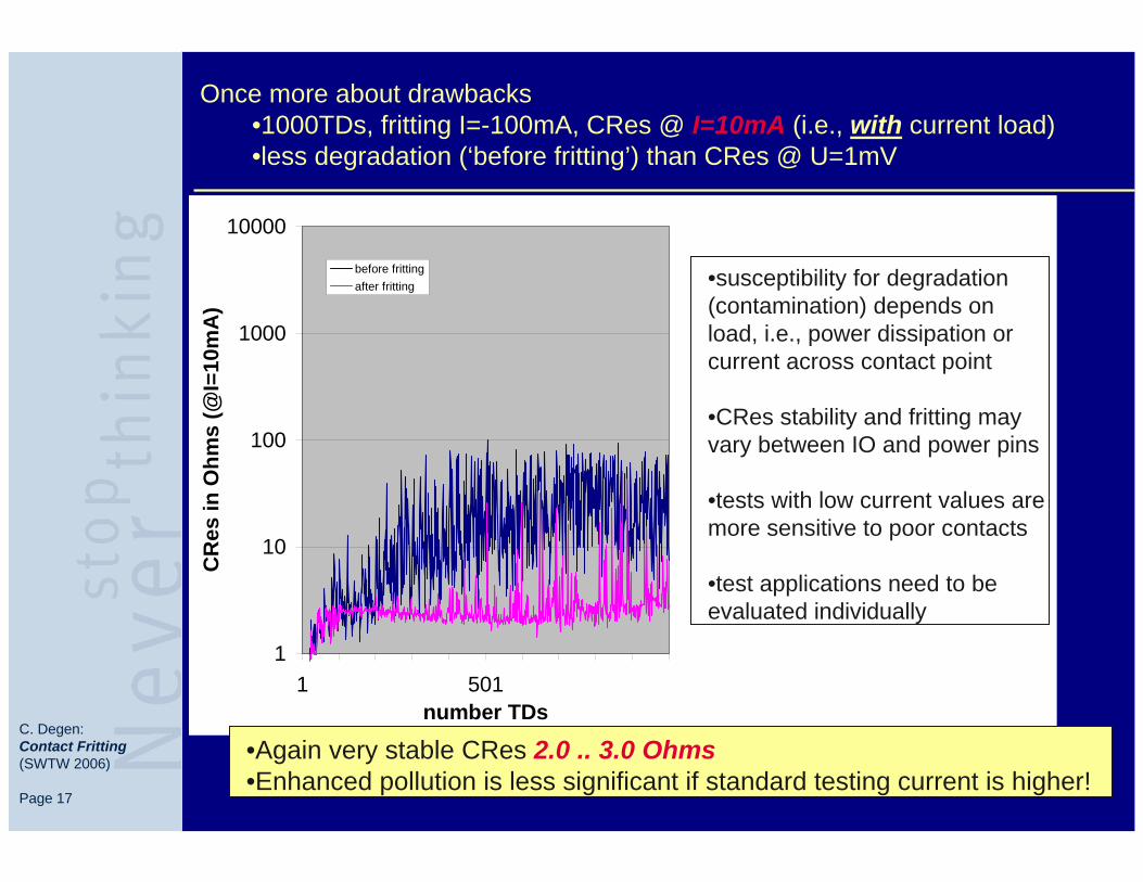
Once more about drawbacks•1000TDs, fritting I=-100mA, CRes @ I=10mA (i.e., with current load)•less degradation (‘before fritting’) than CRes @ U=1mV
1
10
100
1000
10000
1 501number TDs
CR
es in
Ohm
s (@
I=10
mA
)
before frittingafter fritting •susceptibility for degradation
(contamination) depends on load, i.e., power dissipation or current across contact point
•CRes stability and fritting may vary between IO and power pins
•tests with low current values are more sensitive to poor contacts
•test applications need to be evaluated individually
•Again very stable CRes 2.0 .. 3.0 Ohms•Enhanced pollution is less significant if standard testing current is higher!

C. Degen: Contact Fritting (SWTW 2006)
Page 18
How significant is fritting enhanced contamination?-> Comparison of fritting OFF / ON / OFF

C. Degen: Contact Fritting (SWTW 2006)
Page 19
Fritting OFF-ON-OFF:contact conditioning and subsequent probe degradation
BC
Res
@I=
1mA
nofri
tting C
CR
es@
I=1m
Afri
tting
ON P
CR
es@
I=1m
Afri
tting
OFF D
CR
es@
I=10
mA
nofri
tting E
CR
es@
I=10
mA
fritti
ng O
N LC
Res
@I=
10m
Afri
tting
OFF F
CR
es@
I=30
mA
nofri
tting G
CR
es@
I=30
mA
fritti
ng O
N MC
Res
@I=
30m
Afri
tting
OFF H
CR
es@
I=10
0mA
nofri
tting
IC
Res
@I=
100m
Afri
tting
ON J
CR
es@
I=10
0mA
fritti
ng O
FF
0
10
20
30fritting: I=-100mA(200TD per box)
CRes@I=1mA CRes@I=10mA CRes@I=30mA CRes@I=100mA
CR
es in
Ohm
s
•fritting improves contact stability but makes probes ‘addicted’ to current•negatives effects become negligible for higher testing currents (power pins)

C. Degen: Contact Fritting (SWTW 2006)
Page 20
summary / conclusions
FRITTING WORKS!
•A-fritting starts at voltages <2.5V (Tungsten-Rhenium on Al)
•B-fritting significantly lowers CRes•currents >40mA required (with negative polarity)
•fritting makes ‘addicted‘: after turning fritting off, CRes ishigher than before (current assisted contamination)
•amount of CRes improvement depends on current levelduring testing (operation) mode
☺ fritting is suitable to reduce CRes for power pins where negative effects due to enhanced contamination are less significant
fritting very efficiently reduces CRes also for IO-pins – but probe cleaning / maintenance strategy must be adjusted accordingly in order to control enhanced contamination
fritting cannot substitute online cleaning – but it can stabilize CRes in between cleaning executions

C. Degen: Contact Fritting (SWTW 2006)
Page 21
perspectives
FRITTING WORKS!
currently used in IFX production•fritting used in several test programs but so far only limited productive experience•application in front-end and back-end test•observation of both, yield improvement and enhanced probe wear out
future tasks•adjust fritting parameters according to new findings•re-evaluate yield improvement vs probe wear out•unified recommendations for test development groups
Thank you for your attention !
Recommended