Page1
IMPORTANT: READ MANUAL AND STICKER SAFETY
WARNINGS BEFORE USING THE HOIST
6000lb Vertical Boat Lift Assembly
Instructions, Safety Information, Manual and
Warranty
Proudly made in Michigan
By
NuCraft Metal Products
402 Southline Rd
Roscommon, MI 48653
Manuals and drawings also available online at www.craftlander.com
Page2
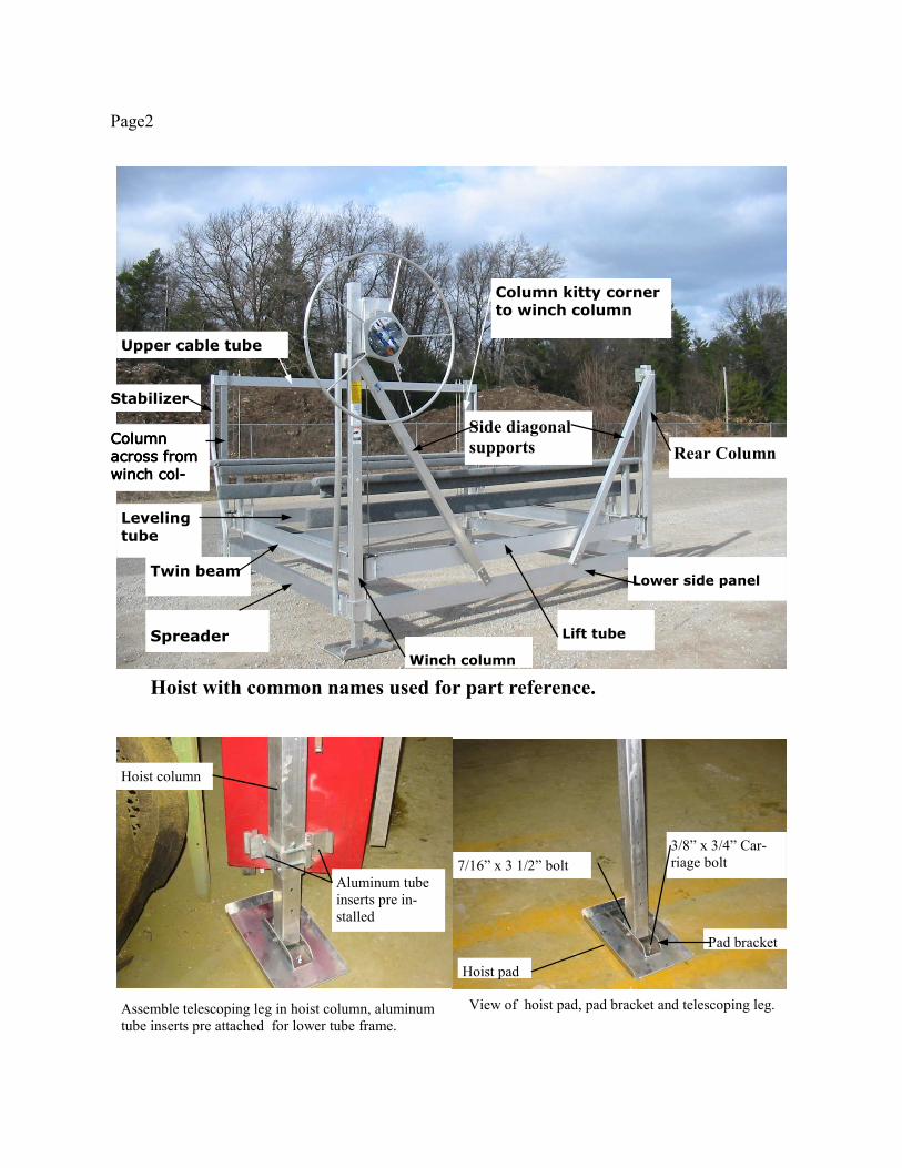
View of hoist pad, pad bracket and telescoping leg.
7/16” x 3 1/2” bolt
3/8” x 3/4” Car-
riage bolt
Hoist pad
Assemble telescoping leg in hoist column, aluminum
tube inserts pre attached for lower tube frame.
Hoist column
Aluminum tube
inserts pre in-
stalled
Column kitty corner
to winch column
Upper cable tube
Leveling
tube
Spreader
Twin beam
Stabilizer
Lift tube
Lower side panel
Winch column
Side diagonal
supports Rear Column
Hoist with common names used for part reference.
Pad bracket
CCCColumn olumn olumn olumn
across from across from across from across from
winch cowinch cowinch cowinch col-l-l-l-
Page3
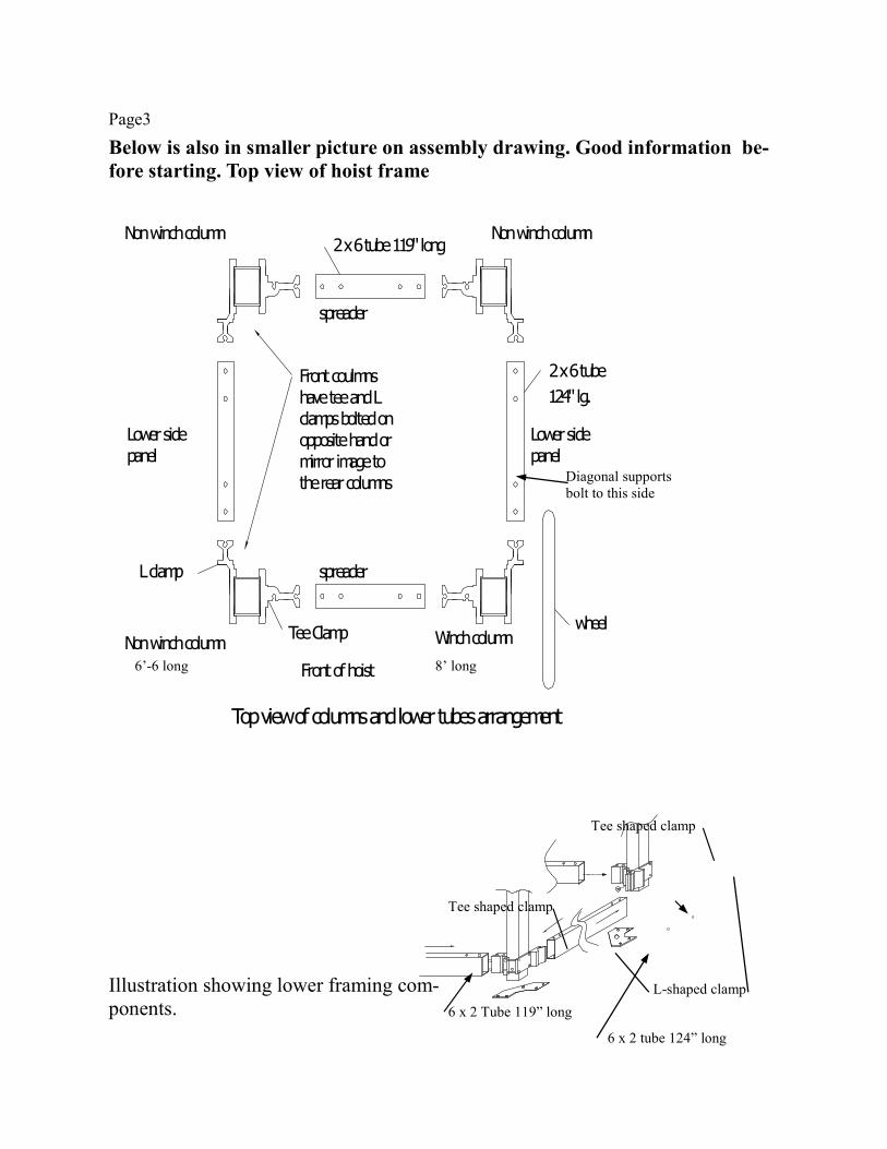
Below is also in smaller picture on assembly drawing. Good information be-
fore starting. Top view of hoist frame
Illustration showing lower framing com-
ponents. L-shaped clamp
Tee shaped clamp
Tee shaped clamp
6 x 2 Tube 119” long
6 x 2 tube 124” long
spreader
Lower side
L clamp
Non winch column
panel
Top view of columns and lower tubes arrangement
Tee Clamp Winch column
Front of hoist
mirror image to
opposite hand or
clamps bolted onhave tee and L
spreader
the rear columns
Front coulmns
wheel
124" lg.
Lower side
panel
2 x 6 tube
Non winch column Non winch column2 x 6 tube 119" long
Diagonal supports
bolt to this side
8’ long 6’-6 long
Page4
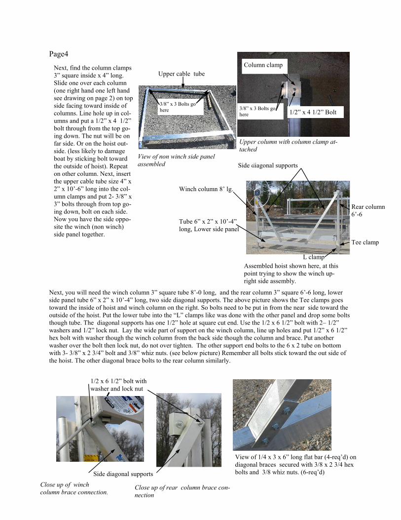
Next, you will need the winch column 3” square tube 8’-0 long, and the rear column 3” square 6’-6 long, lower
side panel tube 6” x 2” x 10’-4” long, two side diagonal supports. The above picture shows the Tee clamps goes
toward the inside of hoist and winch column on the right. So bolts need to be put in from the near side toward the
outside of the hoist. Put the lower tube into the “L” clamps like was done with the other panel and drop some bolts
though tube. The diagonal supports has one 1/2” hole at square cut end. Use the 1/2 x 6 1/2” bolt with 2– 1/2”
washers and 1/2” lock nut. Lay the wide part of support on the winch column, line up holes and put 1/2” x 6 1/2”
hex bolt with washer though the winch column from the back side though the column and brace. Put another
washer over the bolt then lock nut, do not over tighten. The other support end bolts to the 6 x 2 tube on bottom
with 3- 3/8” x 2 3/4” bolt and 3/8” whiz nuts. (see below picture) Remember all bolts stick toward the out side of
the hoist. The other diagonal brace bolts to the rear column similarly.
Upper column with column clamp at-
tached
Column clamp
1/2” x 4 1/2” Bolt
Next, find the column clamps
3” square inside x 4” long.
Slide one over each column
(one right hand one left hand
see drawing on page 2) on top
side facing toward inside of
columns. Line hole up in col-
umns and put a 1/2” x 4 1/2”
bolt through from the top go-
ing down. The nut will be on
far side. Or on the hoist out-
side. (less likely to damage
boat by sticking bolt toward
the outside of hoist). Repeat
on other column. Next, insert
the upper cable tube size 4” x
2” x 10’-6” long into the col-
umn clamps and put 2- 3/8” x
3” bolts through from top go-
ing down, bolt on each side.
Now you have the side oppo-
site the winch (non winch)
side panel together.
Close up of winch
column brace connection. Close up of rear column brace con-
nection
Rear column
6’-6
1/2 x 6 1/2” bolt with
washer and lock nut
Side diagonal supports
Tube 6” x 2” x 10’-4”
long, Lower side panel
Tee clamp
L clamp
Upper cable tube
View of non winch side panel
assembled
View of 1/4 x 3 x 6” long flat bar (4-req’d) on
diagonal braces secured with 3/8 x 2 3/4 hex
bolts and 3/8 whiz nuts. (6-req’d)
3/8” x 3 Bolts go
here
3/8” x 3 Bolts go
here
Winch column 8’ lg.
Side diagonal supports
Assembled hoist shown here, at this
point trying to show the winch up-
right side assembly.
Page5
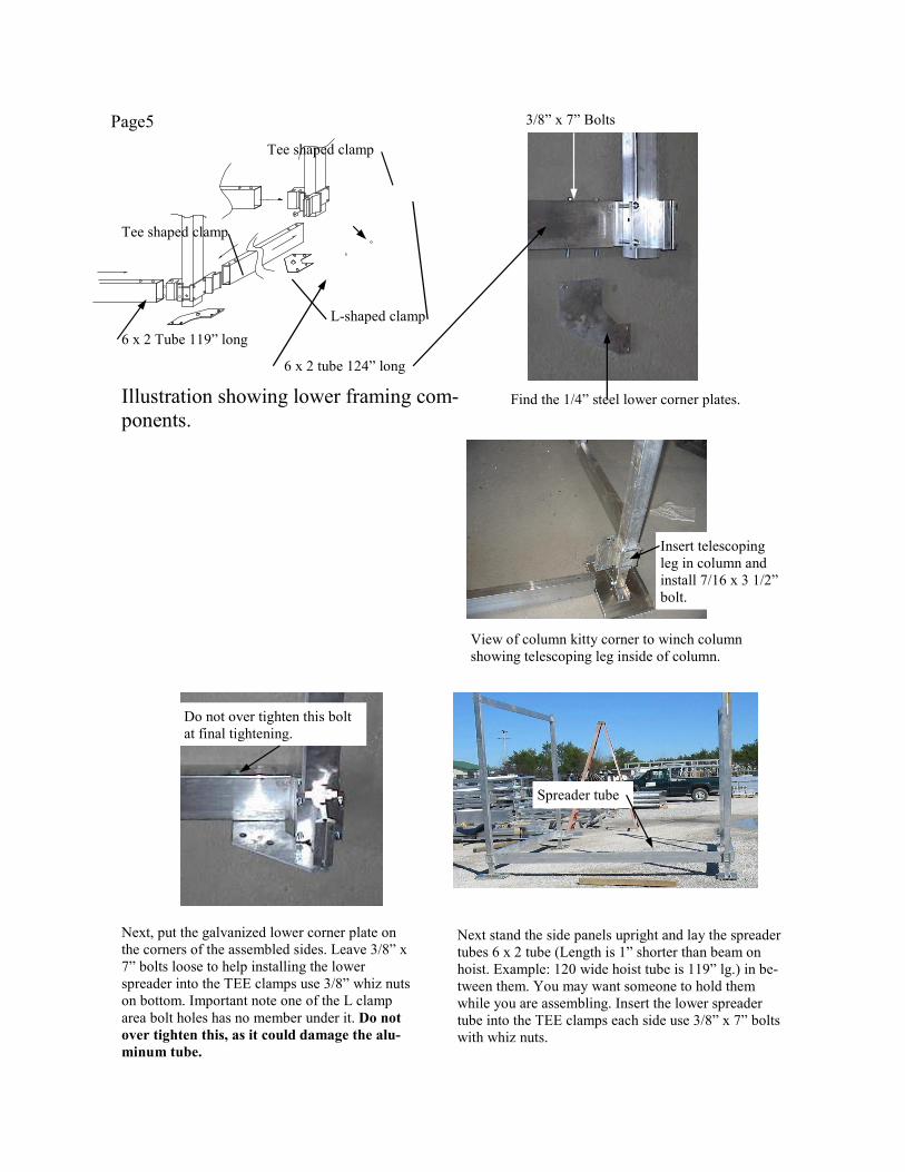
Illustration showing lower framing com-
ponents.
L-shaped clamp
Tee shaped clamp
Tee shaped clamp
Find the 1/4” steel lower corner plates.
3/8” x 7” Bolts
Next, put the galvanized lower corner plate on
the corners of the assembled sides. Leave 3/8” x
7” bolts loose to help installing the lower
spreader into the TEE clamps use 3/8” whiz nuts
on bottom. Important note one of the L clamp
area bolt holes has no member under it. Do not
over tighten this, as it could damage the alu-
minum tube.
Do not over tighten this bolt
at final tightening.
Next stand the side panels upright and lay the spreader
tubes 6 x 2 tube (Length is 1” shorter than beam on
hoist. Example: 120 wide hoist tube is 119” lg.) in be-
tween them. You may want someone to hold them
while you are assembling. Insert the lower spreader
tube into the TEE clamps each side use 3/8” x 7” bolts
with whiz nuts.
Spreader tube
6 x 2 Tube 119” long
6 x 2 tube 124” long
View of column kitty corner to winch column
showing telescoping leg inside of column.
Insert telescoping
leg in column and
install 7/16 x 3 1/2”
bolt.
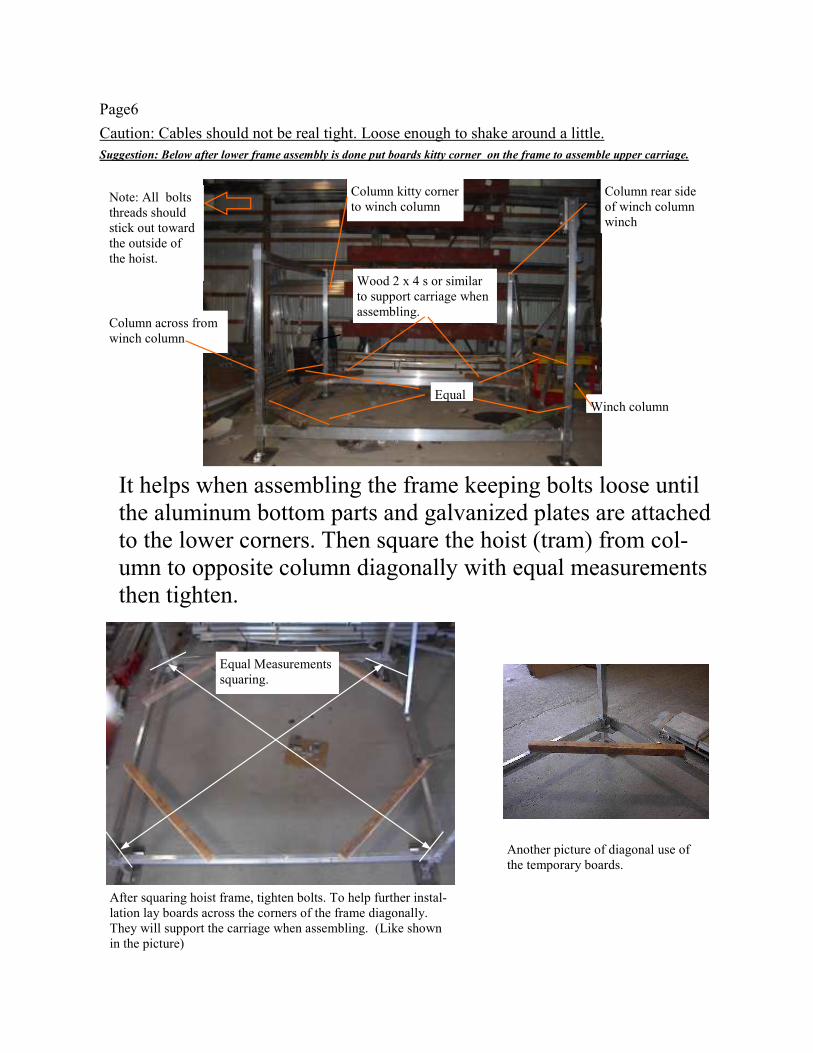
Page6
It helps when assembling the frame keeping bolts loose until
the aluminum bottom parts and galvanized plates are attached
to the lower corners. Then square the hoist (tram) from col-
umn to opposite column diagonally with equal measurements
then tighten.
Equal
Wood 2 x 4 s or similar
to support carriage when
assembling.
Winch column
Column rear side
of winch column
winch
Column kitty corner
to winch column
Column across from
winch column
Note: All bolts
threads should
stick out toward
the outside of
the hoist.
Caution: Cables should not be real tight. Loose enough to shake around a little.
Suggestion: Below after lower frame assembly is done put boards kitty corner on the frame to assemble upper carriage.
Equal Measurements
squaring.
After squaring hoist frame, tighten bolts. To help further instal-
lation lay boards across the corners of the frame diagonally.
They will support the carriage when assembling. (Like shown
in the picture)
Another picture of diagonal use of
the temporary boards.
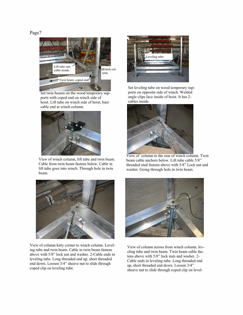
Page7
View of column to the rear of winch column. Twin
beam cable anchors below. Lift tube cable 5/8”
threaded stud fastens above with 5/8” Lock nut and
washer. Going through hole in twin beam.
View of winch column, lift tube and twin beam.
Cable from twin beam fastens below. Cable in
lift tube goes into winch. Through hole in twin
beam.
View of column kitty corner to winch column. Level-
ing tube and twin beam. Cable in twin beam fastens
above with 5/8” lock nut and washer. 2-Cable ends in
leveling tube. Long threaded end up, short threaded
end down. Loosen 3/4” sheave nut to slide through
coped clip on leveling tube.
View of column across from winch column, lev-
eling tube and twin beam. Twin beam cable fas-
tens above with 5/8” lock nuts and washer. 2-
Cable ends in leveling tube. Long threaded end
up, short threaded end down. Loosen 3/4”
sheave nut to slide through coped clip on level-
Set twin beams on the wood temporary sup-
ports with coped end on winch side of
hoist. Lift tube on winch side of hoist, bare
cable end at winch column.
Set leveling tube on wood temporary sup-
ports on opposite side of winch. Welded
angle clips face inside of hoist. It has 2-
cables inside.
Twin beam, coped end
Lift tube one
cable inside. Winch col-
umn
Leveling tube
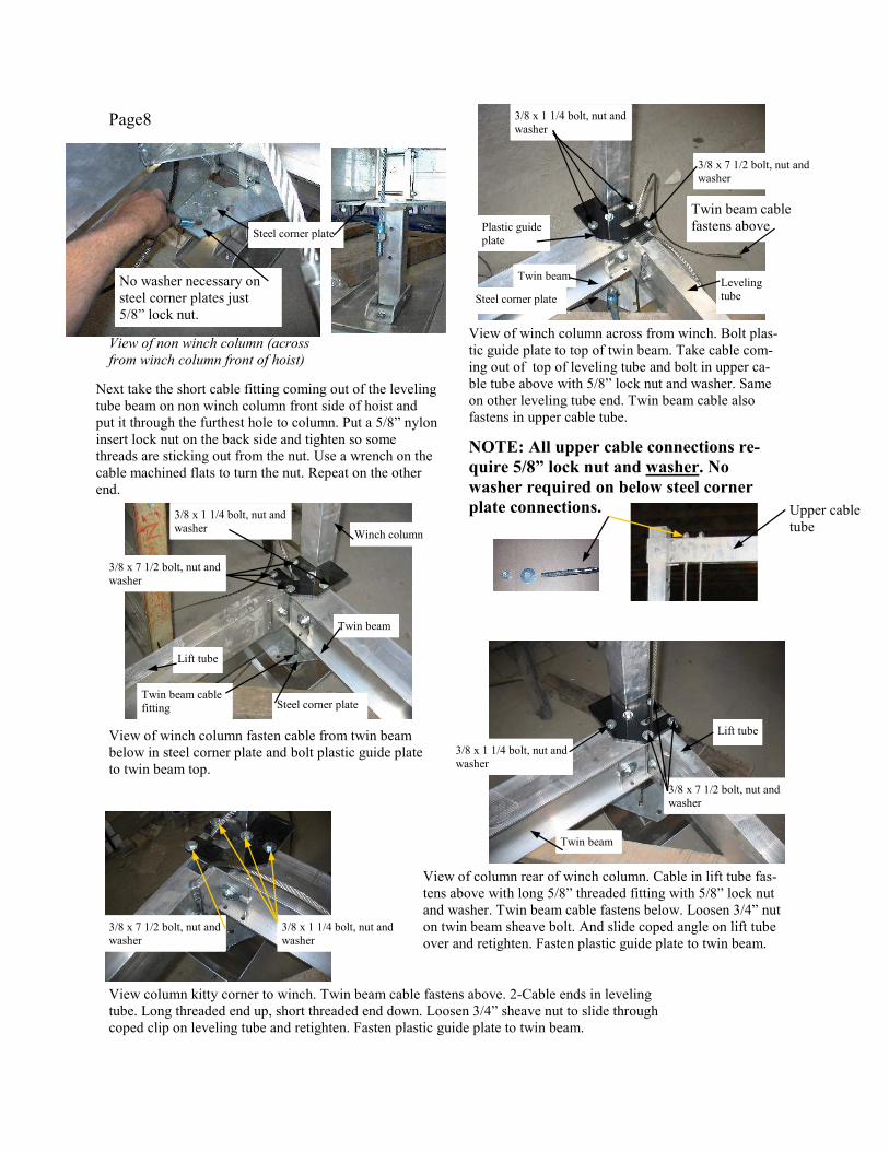
Page8
Next take the short cable fitting coming out of the leveling
tube beam on non winch column front side of hoist and
put it through the furthest hole to column. Put a 5/8” nylon
insert lock nut on the back side and tighten so some
threads are sticking out from the nut. Use a wrench on the
cable machined flats to turn the nut. Repeat on the other
end.
View of non winch column (across
from winch column front of hoist)
View of winch column across from winch. Bolt plas-
tic guide plate to top of twin beam. Take cable com-
ing out of top of leveling tube and bolt in upper ca-
ble tube above with 5/8” lock nut and washer. Same
on other leveling tube end. Twin beam cable also
fastens in upper cable tube.
View of winch column fasten cable from twin beam
below in steel corner plate and bolt plastic guide plate
to twin beam top.
Lift tube
Twin beam
Winch column
Twin beam Leveling
tube
Plastic guide
plate
View column kitty corner to winch. Twin beam cable fastens above. 2-Cable ends in leveling
tube. Long threaded end up, short threaded end down. Loosen 3/4” sheave nut to slide through
coped clip on leveling tube and retighten. Fasten plastic guide plate to twin beam.
View of column rear of winch column. Cable in lift tube fas-
tens above with long 5/8” threaded fitting with 5/8” lock nut
and washer. Twin beam cable fastens below. Loosen 3/4” nut
on twin beam sheave bolt. And slide coped angle on lift tube
over and retighten. Fasten plastic guide plate to twin beam.
3/8 x 1 1/4 bolt, nut and
washer
3/8 x 7 1/2 bolt, nut and
washer
Steel corner plate Twin beam cable
fitting
3/8 x 1 1/4 bolt, nut and
washer
3/8 x 1 1/4 bolt, nut and
washer
3/8 x 7 1/2 bolt, nut and
washer
3/8 x 7 1/2 bolt, nut and
washer
Lift tube
Twin beam
3/8 x 1 1/4 bolt, nut and
washer
3/8 x 7 1/2 bolt, nut and
washer
No washer necessary on
steel corner plates just
5/8” lock nut.
Twin beam cable
fastens above
NOTE: All upper cable connections re-
quire 5/8” lock nut and washer. No
washer required on below steel corner
plate connections.
Steel corner plate
Steel corner plate
Upper cable
tube
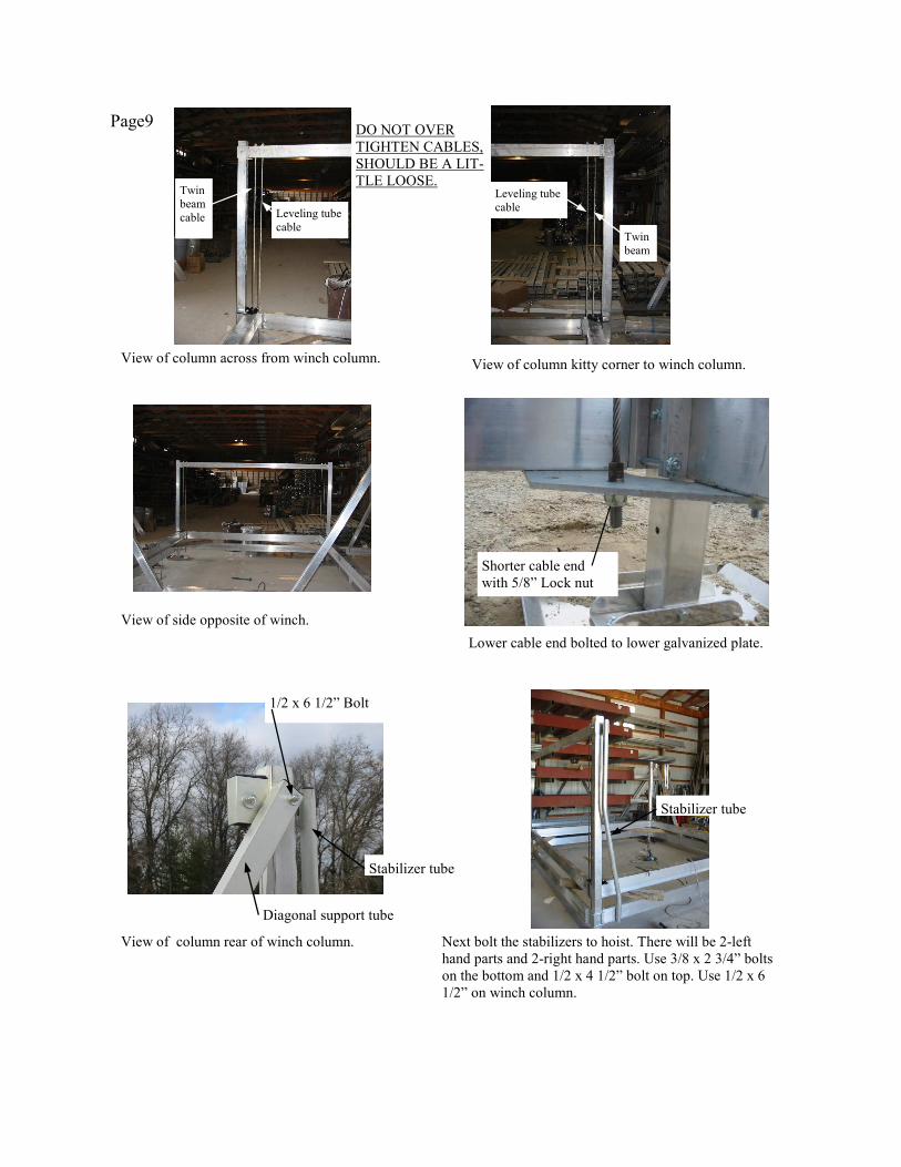
Page9
Lower cable end bolted to lower galvanized plate.
Shorter cable end
with 5/8” Lock nut
View of column across from winch column.
Leveling tube
cable
Twin
beam
cable
Leveling tube
cable
Twin
beam
View of column kitty corner to winch column.
DO NOT OVER
TIGHTEN CABLES,
SHOULD BE A LIT-
TLE LOOSE.
View of side opposite of winch.
View of column rear of winch column. Next bolt the stabilizers to hoist. There will be 2-left
hand parts and 2-right hand parts. Use 3/8 x 2 3/4” bolts
on the bottom and 1/2 x 4 1/2” bolt on top. Use 1/2 x 6
1/2” on winch column.
1/2 x 6 1/2” Bolt
Diagonal support tube
Stabilizer tube
Stabilizer tube
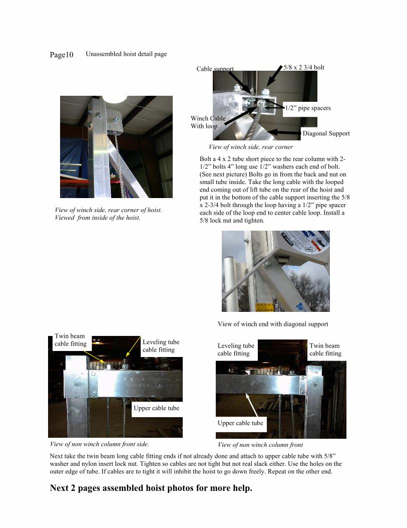
Page10
View of winch side, rear corner
Bolt a 4 x 2 tube short piece to the rear column with 2-
1/2” bolts 4” long use 1/2” washers each end of bolt.
(See next picture) Bolts go in from the back and nut on
small tube inside. Take the long cable with the looped
end coming out of lift tube on the rear of the hoist and
put it in the bottom of the cable support inserting the 5/8
x 2-3/4 bolt through the loop having a 1/2” pipe spacer
each side of the loop end to center cable loop. Install a
5/8 lock nut and tighten.
Next take the twin beam long cable fitting ends if not already done and attach to upper cable tube with 5/8”
washer and nylon insert lock nut. Tighten so cables are not tight but not real slack either. Use the holes on the
outer edge of tube. If cables are to tight it will inhibit the hoist to go down freely. Repeat on the other end.
Twin beam
cable fitting Leveling tube
cable fitting
View of non winch column front side. View of non winch column front
Leveling tube
cable fitting
Twin beam
cable fitting
Upper cable tube
Upper cable tube
5/8 x 2 3/4 bolt Cable support
Diagonal Support
Winch Cable
With loop
View of winch end with diagonal support
1/2” pipe spacers
View of winch side, rear corner of hoist.
Viewed from inside of the hoist.
Unassembled hoist detail page
Next 2 pages assembled hoist photos for more help.
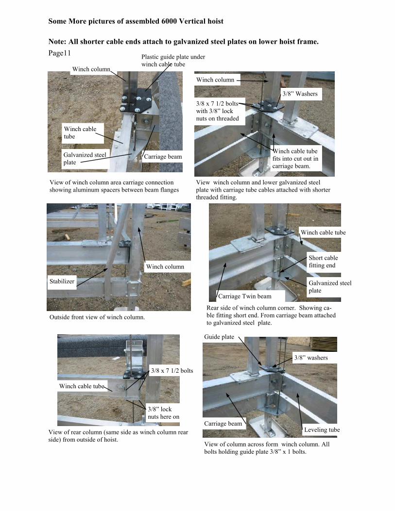
Page11
View of rear column (same side as winch column rear
side) from outside of hoist.
Rear side of winch column corner. Showing ca-
ble fitting short end. From carriage beam attached
to galvanized steel plate.
View of column across form winch column. All
bolts holding guide plate 3/8” x 1 bolts.
Leveling tube
Guide plate
View of winch column area carriage connection
showing aluminum spacers between beam flanges
View winch column and lower galvanized steel
plate with carriage tube cables attached with shorter
threaded fitting.
3/8” washers
Winch cable
tube
Carriage beam
Winch column
Plastic guide plate under
winch cable tube
Galvanized steel
plate
3/8” Washers
Winch column
3/8” lock
nuts here on
Winch cable tube
Winch cable tube
Galvanized steel
plate Carriage Twin beam
Short cable
fitting end
3/8 x 7 1/2 bolts
with 3/8” lock
nuts on threaded
3/8 x 7 1/2 bolts
Note: All shorter cable ends attach to galvanized steel plates on lower hoist frame.
Winch cable tube
fits into cut out in
carriage beam.
Carriage beam
Winch column
Outside front view of winch column.
Stabilizer
Some More pictures of assembled 6000 Vertical hoist
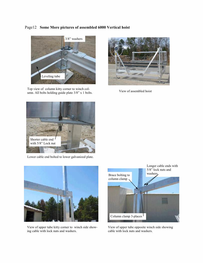
Page12
Top view of column kitty corner to winch col-
umn. All bolts holding guide plate 3/8” x 1 bolts.
Lower cable end bolted to lower galvanized plate.
View of upper tube opposite winch side showing
cable with lock nuts and washers.
3/8” washers
Shorter cable end
with 5/8” Lock nut
Column clamp 3-places
Longer cable ends with
5/8” lock nuts and
washers
Leveling tube
Brace bolting to
column clamp
View of upper tube kitty corner to winch side show-
ing cable with lock nuts and washers.
View of assembled hoist
Some More pictures of assembled 6000 Vertical hoist
Page13
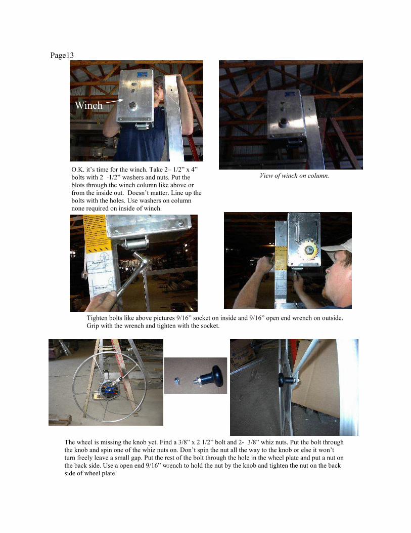
O.K. it’s time for the winch. Take 2– 1/2” x 4”
bolts with 2 -1/2” washers and nuts. Put the
blots through the winch column like above or
from the inside out. Doesn’t matter. Line up the
bolts with the holes. Use washers on column
none required on inside of winch.
View of winch on column.
Tighten bolts like above pictures 9/16” socket on inside and 9/16” open end wrench on outside.
Grip with the wrench and tighten with the socket.
The wheel is missing the knob yet. Find a 3/8” x 2 1/2” bolt and 2- 3/8” whiz nuts. Put the bolt through
the knob and spin one of the whiz nuts on. Don’t spin the nut all the way to the knob or else it won’t
turn freely leave a small gap. Put the rest of the bolt through the hole in the wheel plate and put a nut on
the back side. Use a open end 9/16” wrench to hold the nut by the knob and tighten the nut on the back
side of wheel plate.
Winch
Page14
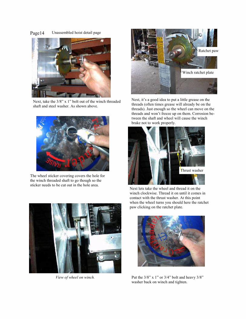
Next, take the 3/8” x 1” bolt out of the winch threaded
shaft and steel washer. As shown above.
Next, it’s a good idea to put a little grease on the
threads (often times grease will already be on the
threads). Just enough so the wheel can move on the
threads and won’t freeze up on them. Corrosion be-
tween the shaft and wheel will cause the winch
brake not to work properly.
Winch ratchet plate
Ratchet paw
The wheel sticker covering covers the hole for
the winch threaded shaft to go though so the
sticker needs to be cut out in the hole area. Next lets take the wheel and thread it on the
winch clockwise. Thread it on until it comes in
contact with the thrust washer. At this point
when the wheel turns you should here the ratchet
paw clicking on the ratchet plate.
Thrust washer
View of wheel on winch. Put the 3/8” x 1” or 3/4” bolt and heavy 3/8”
washer back on winch and tighten.
Unassembled hoist detail page
Page15
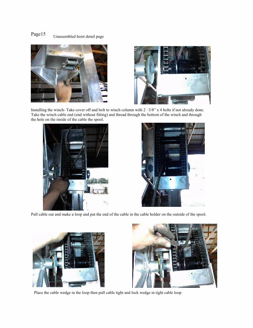
Installing the winch- Take cover off and bolt to winch column with 2 –3/8” x 4 bolts if not already done.
Take the winch cable end (end without fitting) and thread through the bottom of the winch and through
the hole on the inside of the cable the spool.
Pull cable out and make a loop and put the end of the cable in the cable holder on the outside of the spool.
Place the cable wedge in the loop then pull cable tight and lock wedge in tight cable loop
Unassembled hoist detail page
Page16
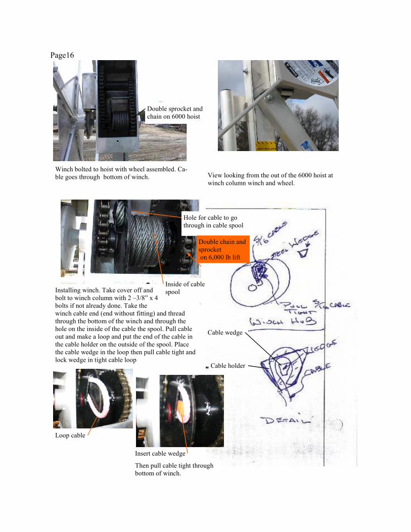
Installing winch. Take cover off and
bolt to winch column with 2 –3/8” x 4
bolts if not already done. Take the
winch cable end (end without fitting) and thread
through the bottom of the winch and through the
hole on the inside of the cable the spool. Pull cable
out and make a loop and put the end of the cable in
the cable holder on the outside of the spool. Place
the cable wedge in the loop then pull cable tight and
lock wedge in tight cable loop
Inside of cable
spool
Cable holder
Cable wedge
Loop cable
Insert cable wedge
Then pull cable tight through
bottom of winch.
Winch bolted to hoist with wheel assembled. Ca-
ble goes through bottom of winch.
Hole for cable to go
through in cable spool
Double chain and
sprocket
on 6,000 lb lift
Double sprocket and
chain on 6000 hoist
View looking from the out of the 6000 hoist at
winch column winch and wheel.
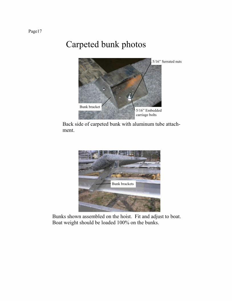
Page17
Back side of carpeted bunk with aluminum tube attach-
ment.
Bunks shown assembled on the hoist. Fit and adjust to boat.
Boat weight should be loaded 100% on the bunks.
Carpeted bunk photos
5/16” Serrated nuts
5/16” Embedded
carriage bolts
Bunk bracket
Bunk brackets
Page18
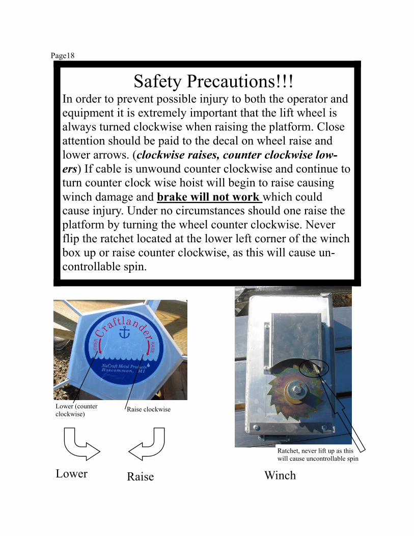
Safety Precautions!!! In order to prevent possible injury to both the operator and
equipment it is extremely important that the lift wheel is
always turned clockwise when raising the platform. Close
attention should be paid to the decal on wheel raise and
lower arrows. (clockwise raises, counter clockwise low-
ers) If cable is unwound counter clockwise and continue to
turn counter clock wise hoist will begin to raise causing
winch damage and brake will not work which could cause injury. Under no circumstances should one raise the
platform by turning the wheel counter clockwise. Never
flip the ratchet located at the lower left corner of the winch
box up or raise counter clockwise, as this will cause un-
controllable spin.
Lower (counter
clockwise) Raise clockwise
Raise Lower
Ratchet, never lift up as this
will cause uncontrollable spin
Winch
Page19
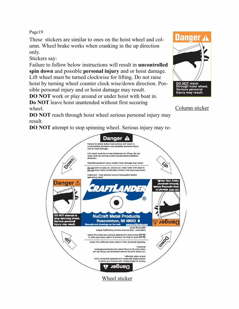
These stickers are similar to ones on the hoist wheel and col-
umn. Wheel brake works when cranking in the up direction
only.
Stickers say:
Failure to follow below instructions will result in uncontrolled
spin down and possible personal injury and or hoist damage. Lift wheel must be turned clockwise for lifting. Do not raise
hoist by turning wheel counter clock wise/down direction. Pos-
sible personal injury and or hoist damage may result.
DO NOT work or play around or under hoist with boat in.
Do NOT leave hoist unattended without first securing wheel.
DO NOT reach through hoist wheel serious personal injury may result.
DO NOT attempt to stop spinning wheel. Serious injury may re-
Column sticker
Wheel sticker
Page20
After the hoist is installation is complete, it is important to next check and see that the winch mechanism is
functioning properly. You can do this by raising the empty platform up about a 1/3 of the way up and releasing
your grasp on the lift wheel. If the winch is operating properly, clutch brake will automatically hold the plat-
form (described as carriage sometimes). Repeat at higher locations. Next repeat this with your boat on the hoist.
If the lift wheel begins to spin down freely from any of these test positions, at no time should you attempt to
prevent it from doing so. Such action could result in injury to arms and hands. Instead simply let the platform
spin down into the water. Doing so will neither damage your boat or hoist.
If for some reason your winch mechanism does not function as described call you local Craftlander dealer. Do
not tamper with winch mechanism.
It is recommended that your Craftlander be thoroughly inspected at least once a season. Tighten all bolts.
Check all pulleys and make sure they are turning freely. Inspect all cables for fraying, wearing or deteriorating.
If any signs appear, replace cables. Check frame thoroughly. Grease the winch drive chain. Turn lift wheel off
shaft. Remove washer and grease threads on winch do not grease clutch plate on winch. Check for rust on
clutch plate and sand and clean off if needed. Install wheel back on lift with retaining bolt and washer and fol-
low the raising instructions in this manual.
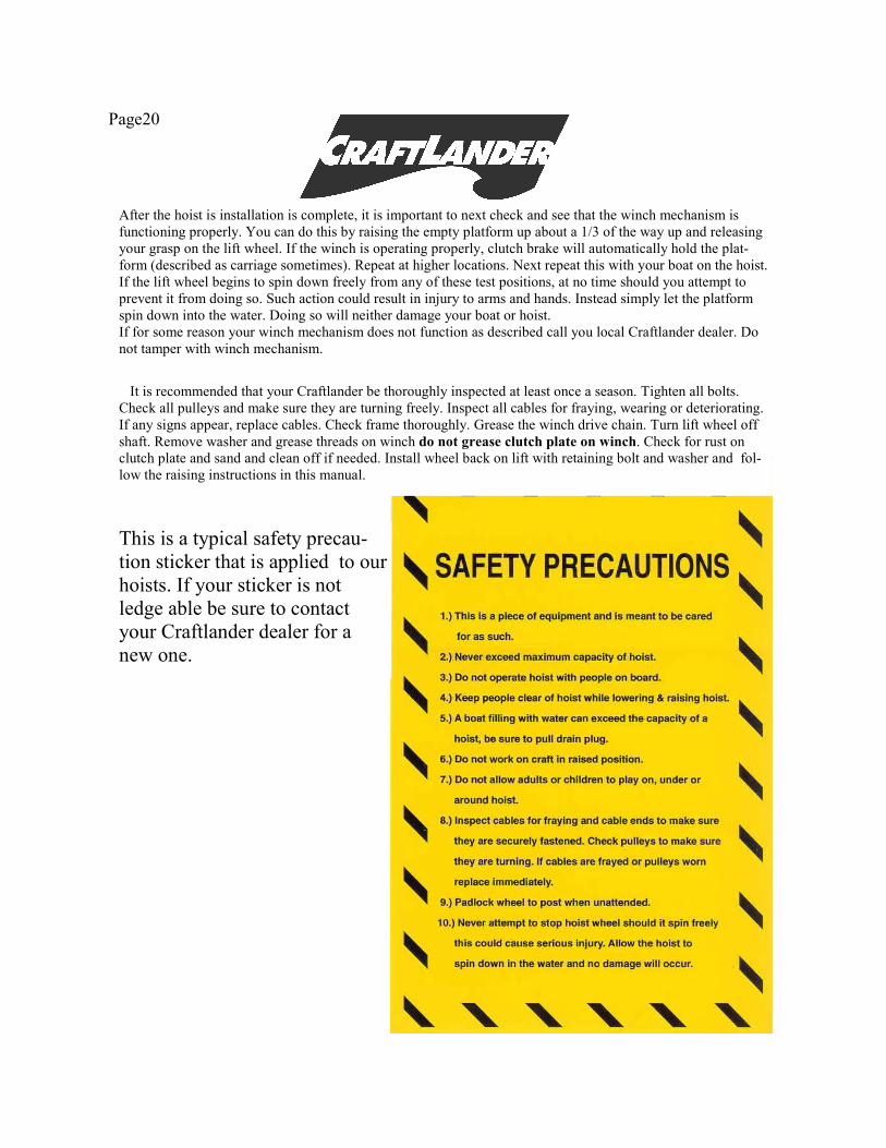
This is a typical safety precau-
tion sticker that is applied to our
hoists. If your sticker is not
ledge able be sure to contact
your Craftlander dealer for a
new one.
Page21
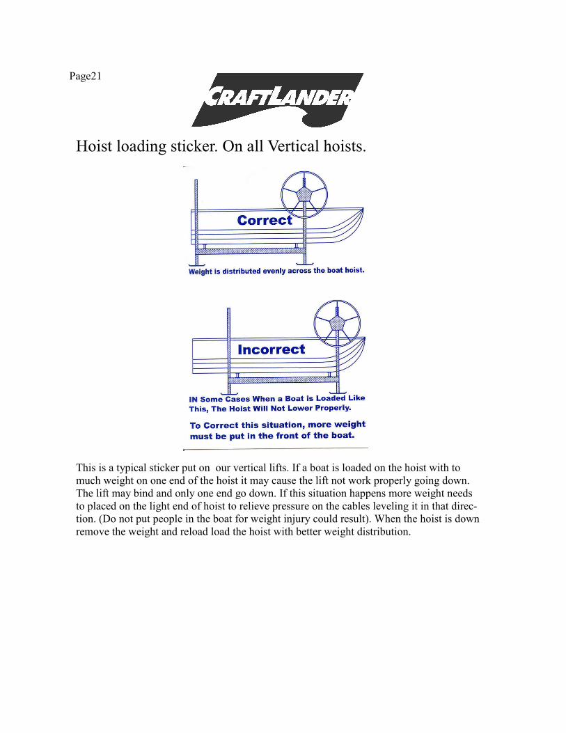
Hoist loading sticker. On all Vertical hoists.
This is a typical sticker put on our vertical lifts. If a boat is loaded on the hoist with to
much weight on one end of the hoist it may cause the lift not work properly going down.
The lift may bind and only one end go down. If this situation happens more weight needs
to placed on the light end of hoist to relieve pressure on the cables leveling it in that direc-
tion. (Do not put people in the boat for weight injury could result). When the hoist is down
remove the weight and reload load the hoist with better weight distribution.
Page22
Craftlander Boat Hoists
Your Craftlander Hoist Limited Warranties During the terms of the Limited Warranties on your aluminum Craftlander hoist, NuCraft Metal Products, Inc.
(hereafter referred to as “NuCraft”) covers the cost of all parts and labor needed to repair or replace any NuCraft
supplied item that proves defective in material, workmanship or factory preparation. These repairs or replacements
(parts and labor) will be made by your dealer at no charge using new or remanufactured parts.
Your Legal Rights Under NuCraft’s Limited Warranties All of the NuCraft Limited Warranties stated in this booklet are the only express written warranties made by
NuCraft applicable to the aluminum Craftlander hoist. These Limited Warranties give you specific legal rights and
you may also have other rights which vary from state to state. You may have some implied warranties, depending
on the state in which your aluminum hoist is registered.
For example, you may have:
1. An “implied warranty of fitness for a particular purpose,” (that your hoist is reasonably fit for the general pur-
pose for which it was sold);
2. An “implied warranty of fitness for a particular purpose,” (that your hoist is suitable for your special purposes;
if your special purposes were specifically disclosed to NuCraft itself-not merely to the distributor or dealer-prior to
purchase.)
These implied warranties are limited, to the extent allowed by law, to the time period covered by the written war-
ranties set forth in this publication. Some states do not allow limitations on how long an implied warranty lasts, so
the above limitations may not apply to you.
SUBSEQUENT BUYER/OWNER This Warranty is extended only to the first buyer/owner of the hoist. This is defined as the first legal owner of a
NuCraft aluminum Craftlander other than an authorized Distrubutor or Dealer who has bought the hoist from
NuCraft for resale to the public.
HOIST ALTERATION This warranty does not cover alteration of the aluminum Craftlander hoist, or failure of hoist components caused
by such alteration.
PRODUCTION CHANGES NuCraft and its distributors/dealers reserve the right to make changes in aluminum Craftlander hoists built and/or
sold by them at any time without incurring any obligation to make the same or similar changes on hoists previously
built and/or sold by them.
Your 2-Year Basic Limited Warranty WHAT IS COVERED:
The 2-Year “Basic Warranty” covers every NuCraft supplied part on your aluminum Craftlander hoist and alumi-
num canopy support frame.
Page23
The “Basic Warranty” begins on your hoist’s Warranty Start Date. The Warranty Start Date is the earlier of (1)
the date you take delivery of your new aluminum Craftlander hoist, OR (2) the date the hoist was first put into
service (for example, as a dealer “demo” or as a NuCraft company hoist). The “Basic
Warranty” lasts for 2 years (24 months) from this date.
The “Basic Warranty” covers the cost of all parts and labor needed to repair any item on your aluminum Craft-
lander hoist that is defective in material, workmanship or factory preparation. You pay nothing for these re-
pairs.
Your 15-Year Fabricated Frame & Extrusion Warranty WHAT IS COVERED:
The “Frame and Extrusion Warranty” covers these parts and components of your aluminum Craftlander hoist
frame for 15 years counted from your hoist’s Warranty Start Date:
Extruded Aluminum: columns, rails, spreaders, crossmembers, “Twin Beams”, legs, stands, extensions, canopy
inserts, bows, rails, and clamps.
Fabricated: hoist wheel, winch, corner brackets, column guide plates, and footpads.
What your NuCraft Limited Warranties Do Not Cover Vinyl canopy covers are covered by a 5-Year Limited Warranty by the material manufacturer.
Your NuCraft Limited Warranties do not cover the costs of repairing damage caused by environmental factors
or acts of God. “Environmental factors” include such things as airborne fallout, chemicals, tree sap, salt, ocean
spray, and water hazards. “Acts of God” include such things as hailstorms, windstorms, tornadoes, sandstorms,
lightning, floods and earthquakes.
Your NuCraft Limited Warranties do not cover the costs of repairing damage caused by poor or improper
maintenance.
Your NuCraft Limited Warranties do not cover the costs of normal/scheduled maintenance of your aluminum
Craftlander hoist. They do not cover the cost of lubrication, replacing cables or fasteners unless done as the re-
sult of repair covered by your 2-year “Basic Warranty”.
Your NuCraft Limited Warranties do not cover the costs of repairing damage or conditions caused by fire or
accident; by abuse or negligence; by misuse: by tampering with parts; by improper adjustment or alteration; or
by any changes made to your aluminum Craftlander hoist; the cost of rental hoist or slip; gasoline, telephone,
travel or lodging; the loss of personal or commercial property; the loss of revenue, etc. NOTE: Some states do
not allow the exclusion or limitation of incidental or consequential damages, so the above limitations or exclu-
sions may not apply to you.
How To Get Warranty Service for Your Hoist Please contact the dealer from whom you bought the hoist for warranty service. When contacting your dealer,
please provide them with your hoist’s model number, hoist serial number, date of purchase and the nature of
the problem. If contact with the dealer is not feasible, please contact NuCraft Metal Products for further assis-
tance.
Proudly Made in Michigan
By
NuCraft Metal Products
402 Southline Rd.
Roscommon, MI 48653
Recommended