1
MICROCONTROLLER BASED LPG GAS DETECTOR USING GSM MODULE
Ashish Sharma (B.Tech., EL Engg.)
E-mail: [email protected]
ABSTRACT
Ideal gas sensor is used to detect the presence of a dangerous LPG leak in your car or in a service station, storage tank environment. This unit can be easily incorporated into an alarm unit, to sound an alarm or give a visual indication of the LPG concentration. The sensor has excellent sensitivity combined with a quick response time. The sensor can also sense iso-butane, propane, LNG and cigarette smoke.
If the LPG sensor senses any gas leakage from storage the output of this sensor goes low. This low signal is monitored by the microcontroller and it will identify the gas leakage. Now the microcontroller is turn on LED and Buzzer. After few milliseconds delay, it also turn on exhaust fan for throwing gas out and continue send messages as „GAS LEAKAGE‟ to a mobile no. ,
written in c-code.
INTRODUCTION
MQ-5 Semiconductor Sensor for Combustible Gas Sensitive material of MQ-5 gas sensor is SnO2, which with lower conductivity in clean air. When the target combustible gas exist, the sensors conductivity is higher along with the gas concentration rising. We use simple electro-circuit, convert change of conductivity to correspond output signal of gas concentration. MQ-5 gas sensor has high sensitivity to Methane, Propane and Butane and could be used to detect both Methane and Propane. The sensor could be used to detect different combustible gas especially Methane, it is with low cost and suitable for different application.

2
BLOCK DIAGRAM
BLOCK DIAGRAM DESCRIPTION
MQ-5 LPG SENSOR
It senses the leakage of LPG. The out put of this sensor is „high‟ at normal condition. The output
goes low, when it senses the LPG.
MICROCONTROLLER
It is the whole control of the project. It controls the Exhaust fan, LED, Buzzer and when LPG leak occurs. The input/ output ports of the microcontroller is used for this.
EXHAUST FAN
This is used to send out the LPG to space and then the concentration of LPG is reduced.
Buzzer
When buzzer is blowing, this indicates the leakage of LPG gas. It is 12 V DC operated buzzer.
LED
When LED is glowing, this indicates the leakage of LPG gas. It is 1.2 V DC operated LED.

3
MQ-5 LPG GAS DETECTOR MODULE
MQ-5 LPG GAS Sensor
PRESET Vcc
GND
Output
OP-AMP Ic
Power Indicator LED
Output Indicator LED

4
SPECIFICATIONS OF MQ-5 LPG GAS SENSOR

5

6
WORKING PRINCIPLE The sensing material in TGS gas sensors is metal oxide, most typically SnO2. When a metal oxide crystal such as SnO2 is heated at a certain high temperature in air, oxygen is adsorbed on the crystal surface with a negative charge. Then donor electrons in the crystal surface are transferred to the adsorbed oxygen, resulting in leaving positive charges in a space charge layer. Thus, surface potential is formed to serve as a potential barrier against electron flow. Inside the sensor, electric current flows through the conjunction parts (grain boundary) of SnO2 micro crystals. At grain boundaries, adsorbed oxygen forms a potential barrier which prevents carriers from moving freely. The electrical resistance of the sensor is attributed to this potential barrier. In the presence of a deoxidizing gas, the surface density of the negatively charged oxygen decreases, so the barrier height in the grain boundary is reduced. The reduced barrier height decreases sensor resistance. ATMEGA16 MICROCONTROLLER DETAILS DESCRIPTION The ATMEGA16 is a low-power, high-performance CMOS 8-bit microcomputer with 16K bytes of Flash programmable and erasable read only memory (EPROM). The device is manufactured using Atmel‟s high-density nonvolatile memory technology and is compatible with the industry-standard MCS-51 instruction set and pin out. The on-chip Flash allows the program memory to be reprogrammed in-system or by a conventional nonvolatile memory programmer. By combining a versatile 8-bit CPU with Flash on a monolithic chip, the Atmel ATMEGA16 is a powerful microcomputer which provides a highly-flexible and cost-effective solution to many embedded control applications. PIN OUT

7
FEATURES OF ATMEGA16
8
MICROCONTROLLER CIRCUIT WITH PHERIPHERALS
(NOTE: For more details of ATMEGA16, please refer datasheet.)
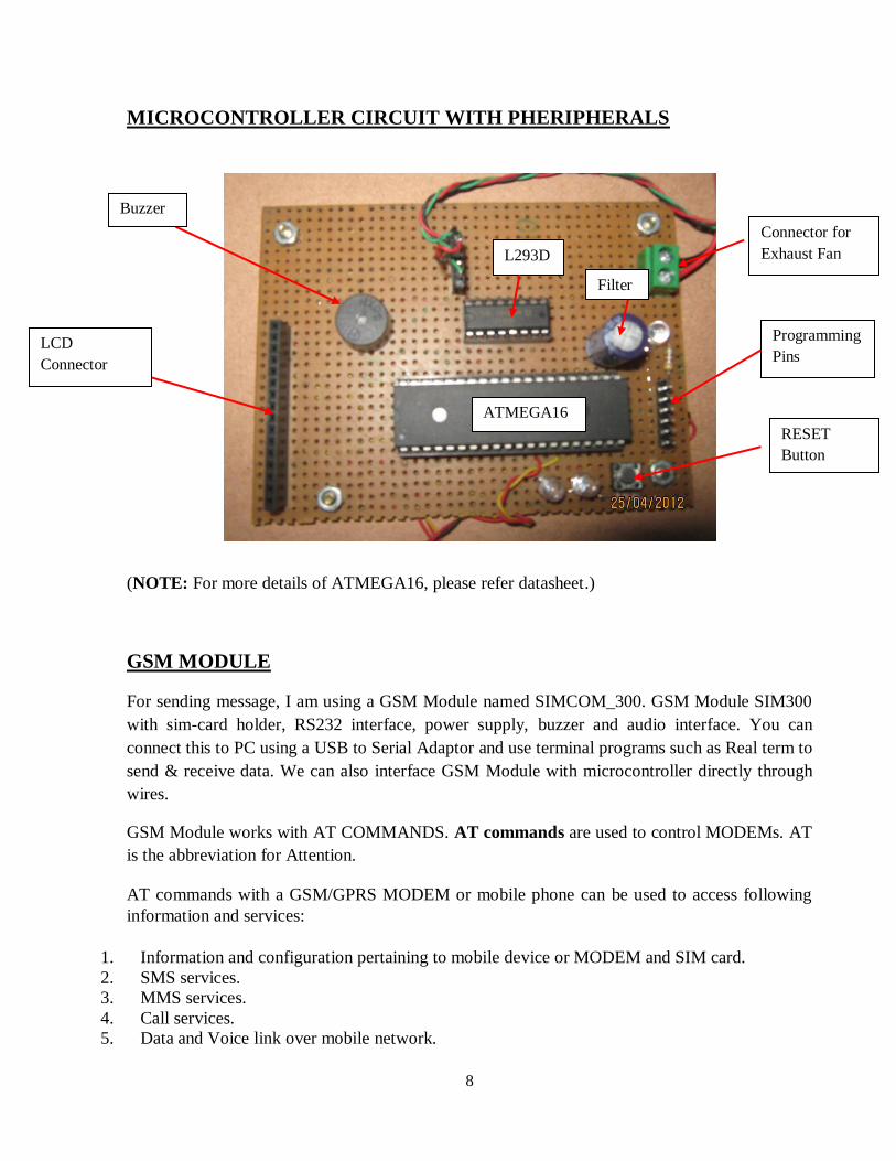
GSM MODULE
For sending message, I am using a GSM Module named SIMCOM_300. GSM Module SIM300 with sim-card holder, RS232 interface, power supply, buzzer and audio interface. You can connect this to PC using a USB to Serial Adaptor and use terminal programs such as Real term to send & receive data. We can also interface GSM Module with microcontroller directly through wires.
GSM Module works with AT COMMANDS. AT commands are used to control MODEMs. AT is the abbreviation for Attention.
AT commands with a GSM/GPRS MODEM or mobile phone can be used to access following information and services:
1. Information and configuration pertaining to mobile device or MODEM and SIM card. 2. SMS services. 3. MMS services. 4. Call services. 5. Data and Voice link over mobile network.
Buzzer
ATMEGA16
L293D
Connector for Exhaust Fan
Programming Pins
RESET Button
Filter
LCD Connector

9
SIMCOM_300
(NOTE: For more details of SIMCOM_300 GSM Module, please refer datasheet.)
EXPLANATION OF COMMONLY USED AT COMMANDS
1) AT - This command is used to check communication between the module and the computer. For example, AT OK The command returns a result code OK if the computer (serial port) and module are connected properly. If any of module or SIM is not working, it would return a result code ERROR.
2) +CMGF - This command is used to set the SMS mode. Either text or PDU mode can be selected by assigning 1 or 0 in the command. SYNTAX: AT+CMGF=<mode>
0: for PDU mode 1: for text mode
The text mode of SMS is easier to operate but it allows limited features of SMS. The PDU (protocol data unit) allows more access to SMS services but the operator requires bit level knowledge of TPDUs. The headers and body of SMS are accessed in hex format in PDU mode so it allows availing more features. For example,
AT+CMGF=1
Buzzer
Audio Connector
Antenna
Supply Port
Communication PORT
SIM Card Holder
10
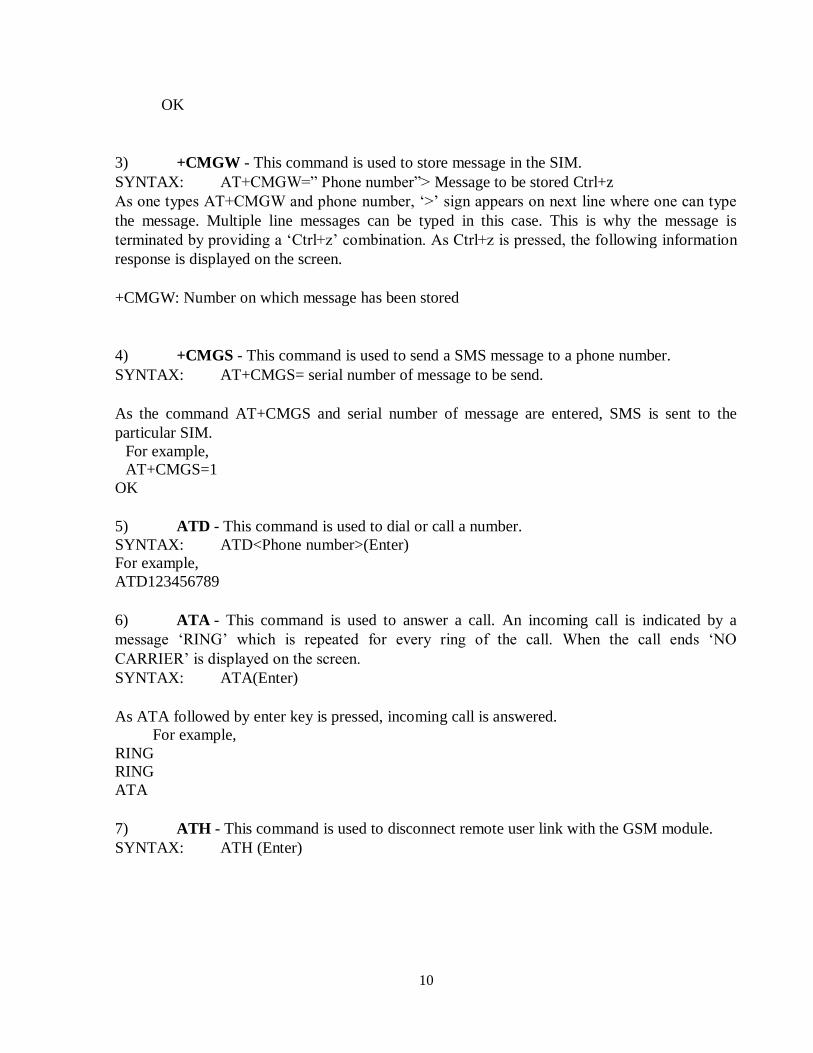
OK
3) +CMGW - This command is used to store message in the SIM. SYNTAX: AT+CMGW=” Phone number”> Message to be stored Ctrl+z As one types AT+CMGW and phone number, „>‟ sign appears on next line where one can type
the message. Multiple line messages can be typed in this case. This is why the message is terminated by providing a „Ctrl+z‟ combination. As Ctrl+z is pressed, the following information response is displayed on the screen. +CMGW: Number on which message has been stored
4) +CMGS - This command is used to send a SMS message to a phone number. SYNTAX: AT+CMGS= serial number of message to be send.
As the command AT+CMGS and serial number of message are entered, SMS is sent to the particular SIM.
For example, AT+CMGS=1
OK
5) ATD - This command is used to dial or call a number. SYNTAX: ATD<Phone number>(Enter) For example, ATD123456789
6) ATA - This command is used to answer a call. An incoming call is indicated by a message „RING‟ which is repeated for every ring of the call. When the call ends „NO
CARRIER‟ is displayed on the screen. SYNTAX: ATA(Enter)
As ATA followed by enter key is pressed, incoming call is answered.
For example, RING RING ATA
7) ATH - This command is used to disconnect remote user link with the GSM module. SYNTAX: ATH (Enter)

11
AVR GSM
230/0-12V
L1
AC230V
1N4007
D1
1N4007
D4
1000uF/25V
C1 LM78051
2
3
IC1
47uF/16V
C2
1N4007
D31N4007
D2
+12V+5V
CONNECTION BETWEEN MICROCONTROLLER AND GSM MODULE
For connection, connect Receiver Pin (Rx) of Microcontroller to Transmitter Pin (Tx) of GSM Module and Transmitter Pin (Tx) of Microcontroller to Receiver Pin (Rx) of GSM Module. Also connect Ground Pin (GND) of both.
POWER SUPPLY
Power supply for the complete unit can be derived from the mains using a step-down transformer of 230V AC primary to 0-12V, 500mA secondary. A full- wave rectifier followed by a capacitor filter is the output voltage and feeds it to the 5-volt regulator (LM7805) whose output is used to the power supply requirements of microcontroller circuit, other IC‟s.
Vcc Vcc
Rx Tx
Tx Rx
GND GND

12
COMPLETE CONNECTION DIAGRAM
GSM Module
Microcontroller Circuit
Exhaust Fan
GAS Sensor Module
Power Supply
Step down Transformer
Power Indicator
Filter
Full Wave Rectifier Ic

13
SCHEMATIC DIAGRAM

14
FLOW CHART DIAGRAM
Start
Power On
MCU sends „AT to
GSM Module‟
Is GSM Module replies „OK‟ ?
Is LPG Sensor‟s
O/P value is greater than threshold value?
Turn on LED & Buzzer
Start Exhaust Fan by enabling the respective PORT
Send message to stored Mobile No.
NO
YES
NO
YES
15
APPLICATIONS
This project is applicable in following fields:
1. Domestic gas leakage detector 2. Industrial Combustible gas detector 3. Portable gas detector 4. Homes 5. Factories 6. LPG storage 7. Gas cars 8. Hotels etc.
CONCLUSION
I have finally succeeded in making the “MICROCONTROLLER BASED LPG GAS DETECTOR USING GSM MODULE” Satisfactorily. More knowledge is gained and more experiences are faced lot of information‟s are collected ultimately, I have concluded with a great pleasure for achieving our aim.
I have planned to fulfill my technical requirements. The knowledge I have attained with this project really would follow till the end of our career.
REFERENCES
1. www.iskyworld.in 2. www.seminarprojects.com 3. www.engineersgarage.com 4. www.datasheets 4u.com
Recommended