2 YEAR WARRANTY
Serial # (located on electrical box cover)
Installation Date
Wiring Type
OWNER'S MANUALMODEL MT
MEDIUM DUTY DOOR OPERATOR
NOT FOR RESIDENTIAL USE
LISTED DOOR OPERATOR
41B6
C2 WiringF A C T O R Y S E T
See page 8 forother wiring
configurations
MOTORTYPE: .................................Intermittent duty
HORSEPOWER: ................1/2 Horsepower
SPEED:...............................1000 RPM
VOLTAGE: .........................115V, 1 Phase, 60Hz230V, 1 Phase, 50Hz
CURRENT: .........................See motor nameplate
2
MECHANICALDRIVE REDUCTION:.............Primary: Heavy duty(4L) V-Belt. Secondary: #48 chain/sprocket. Output:#48 chain
OUTPUT SHAFT SPEED: .....108 R.P.M.
DOOR SPEED: ......................approx. 9” per sec.depending on door
BRAKE (Optional): ...............Solenoid actuated discbrake
BEARINGS: ...........................IronCopper sintered andoil impregnated.
SAFETYDISCONNECT: .............Quick disconnect door arm for
emergency manual door operation.
SENSING DEVICE: ......Accepts photo electric controls such as CPS, or an electric / pneumatic sensing edge can be attached to the bottom edge of door.
A SENSING DEVICE IS STRONGLYRECOMMENDED FOR ALL COMMERCIALOPERATOR INSTALLATIONS. REQUIRED WHENTHE 3 BUTTON CONTROL STATION IS OUT OFSIGHT OF DOOR OR ANY OTHER CONTROL(AUTOMATIC OR MANUAL) IS USED.
SPECIFICATIONS
ELECTRICALTRANSFORMER:.............24VAC
CONTROL STATION: .....NEMA 1 three button station.OPEN/CLOSE/STOP
WIRING TYPE: .................C2 (Factory Shipped) Momentary contact to OPEN & STOP, constantpressure to CLOSE, plus wiring for sensing device toreverse. See page 8 for control wiring options.
LIMIT ADJUST: ................Linear driven, fully adjustable screw type cams.
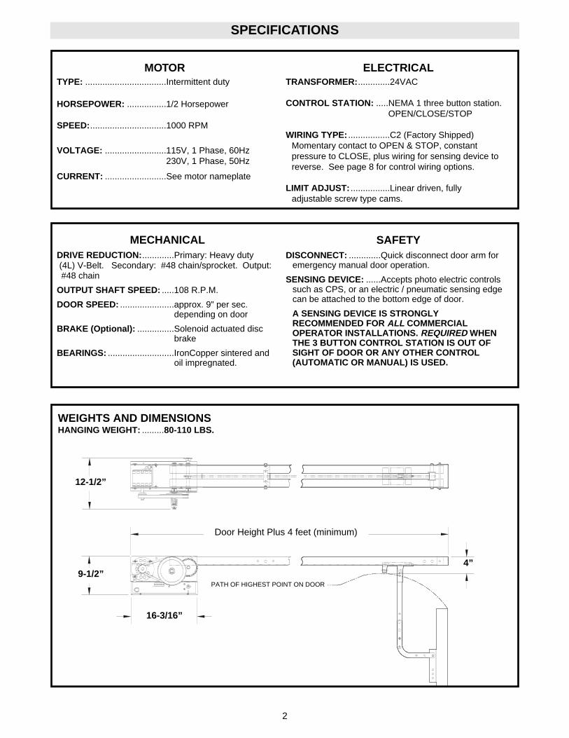
WEIGHTS AND DIMENSIONSHANGING WEIGHT: .........80-110 LBS.
9-1/2”
Door Height Plus 4 feet (minimum)
16-3/16”
PATH OF HIGHEST POINT ON DOOR
4”
12-1/2”
3
PREPARATION
3. Align the track so that the bolts inserted in step 2line up with the L-Slots in the frame.
4. Connect the track to the powerhead by fasteningtwo 3/8"-16 x 3/4" bolts and nuts through the frameand the end holes in track. Tighten all four bolts tosecure the track to the powerhead.
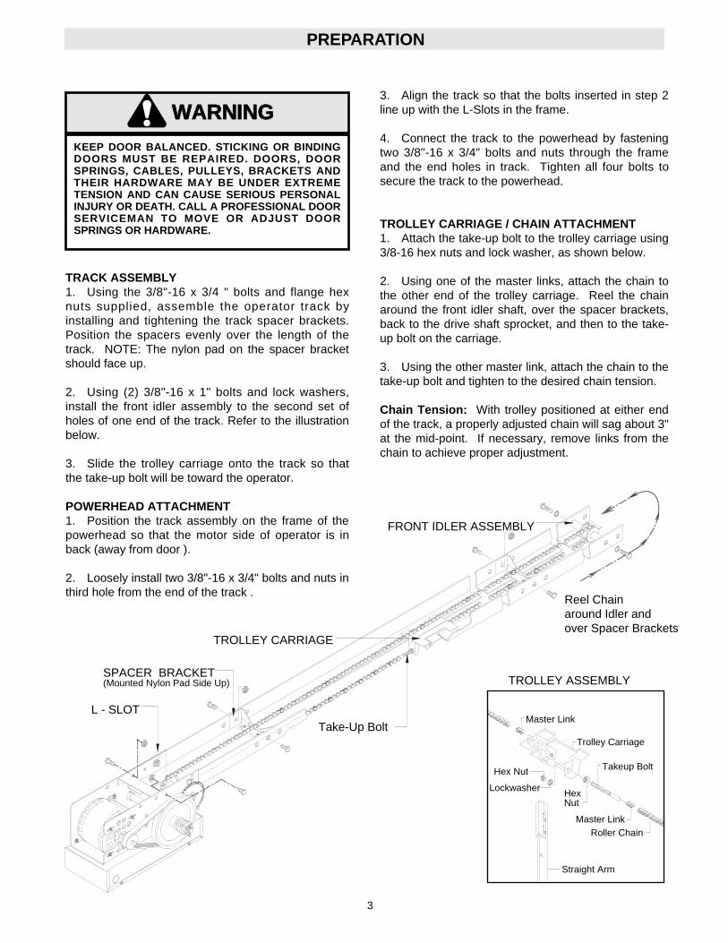
TROLLEY CARRIAGE / CHAIN ATTACHMENT1. Attach the take-up bolt to the trolley carriage using3/8-16 hex nuts and lock washer, as shown below.
2. Using one of the master links, attach the chain tothe other end of the trolley carriage. Reel the chainaround the front idler shaft, over the spacer brackets,back to the drive shaft sprocket, and then to the take-up bolt on the carriage.
3. Using the other master link, attach the chain to thetake-up bolt and tighten to the desired chain tension.
Chain Tension: With trolley positioned at either endof the track, a properly adjusted chain will sag about 3"at the mid-point. If necessary, remove links from thechain to achieve proper adjustment.
KEEP DOOR BALANCED. STICKING OR BINDINGDOORS MUST BE REPAIRED. DOORS, DOORSPRINGS, CABLES, PULLEYS, BRACKETS ANDTHEIR HARDWARE MAY BE UNDER EXTREMETENSION AND CAN CAUSE SERIOUS PERSONALINJURY OR DEATH. CALL A PROFESSIONAL DOORSERVICEMAN TO MOVE OR ADJUST DOORSPRINGS OR HARDWARE.
WARNING
CAUTION
WARNING
WARNING
SPACER BRACKET(Mounted Nylon Pad Side Up)
FRONT IDLER ASSEMBLY
TROLLEY CARRIAGE
L - SLOTMaster Link
Takeup Bolt
Roller ChainMaster Link
HexNut
Straight Arm
Lockwasher
Hex Nut
TROLLEY ASSEMBLY
Take-Up BoltTrolley Carriage
TRACK ASSEMBLY1. Using the 3/8"-16 x 3/4 " bolts and flange hexnuts supplied, assemble the operator track byinstalling and tightening the track spacer brackets.Position the spacers evenly over the length of thetrack. NOTE: The nylon pad on the spacer bracketshould face up.
2. Using (2) 3/8"-16 x 1" bolts and lock washers,install the front idler assembly to the second set ofholes of one end of the track. Refer to the illustrationbelow.
3. Slide the trolley carriage onto the track so thatthe take-up bolt will be toward the operator.
POWERHEAD ATTACHMENT1. Position the track assembly on the frame of thepowerhead so that the motor side of operator is inback (away from door ).
2. Loosely install two 3/8"-16 x 3/4" bolts and nuts inthird hole from the end of the track .
Reel Chainaround Idler andover Spacer Brackets
4
IMPORTANT NOTE: Before the operator is installed, be sure the door has been properly aligned and is workingsmoothly. Although each installation will vary due to particular building characteristics, refer to the following gen-eral procedures to install the operator.
INSTALLATION INSTRUCTIONS
Carpenter'sLevel
HeaderWall
High ArcPoint
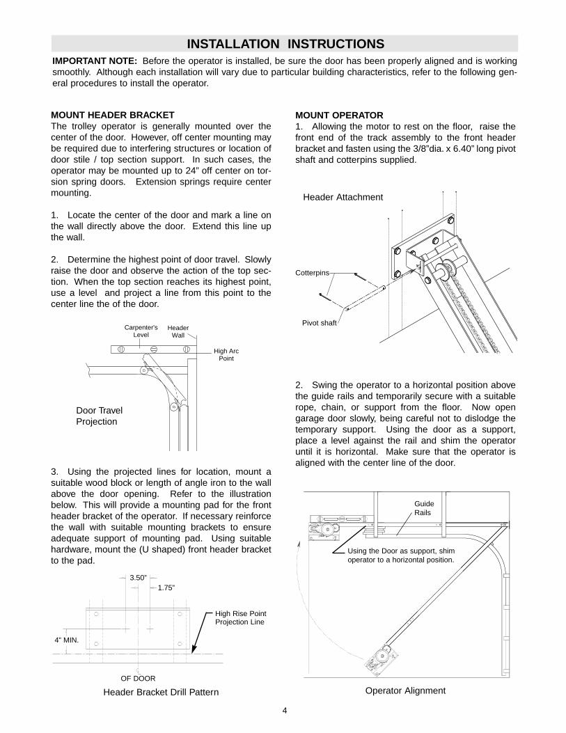
MOUNT HEADER BRACKETThe trolley operator is generally mounted over thecenter of the door. However, off center mounting maybe required due to interfering structures or location ofdoor stile / top section support. In such cases, theoperator may be mounted up to 24” off center on tor-sion spring doors. Extension springs require centermounting.
1. Locate the center of the door and mark a line onthe wall directly above the door. Extend this line upthe wall.
2. Determine the highest point of door travel. Slowlyraise the door and observe the action of the top sec-tion. When the top section reaches its highest point,use a level and project a line from this point to thecenter line the of the door.
MOUNT OPERATOR1. Allowing the motor to rest on the floor, raise thefront end of the track assembly to the front headerbracket and fasten using the 3/8”dia. x 6.40” long pivotshaft and cotterpins supplied.
3. Using the projected lines for location, mount asuitable wood block or length of angle iron to the wallabove the door opening. Refer to the illustrationbelow. This will provide a mounting pad for the frontheader bracket of the operator. If necessary reinforcethe wall with suitable mounting brackets to ensureadequate support of mounting pad. Using suitablehardware, mount the (U shaped) front header bracketto the pad.
Header Bracket Drill Pattern
2. Swing the operator to a horizontal position abovethe guide rails and temporarily secure with a suitablerope, chain, or support from the floor. Now opengarage door slowly, being careful not to dislodge thetemporary support. Using the door as a support,place a level against the rail and shim the operatoruntil it is horizontal. Make sure that the operator isaligned with the center line of the door.
Operator Alignment
Header Attachment
Door TravelProjection
Pivot shaft
Cotterpins
Using the Door as support, shimoperator to a horizontal position.
GuideRails
OF DOOR
3.50”1.75”
4” MIN.
High Rise PointProjection Line
5
INSTALLATION INSTRUCTIONS
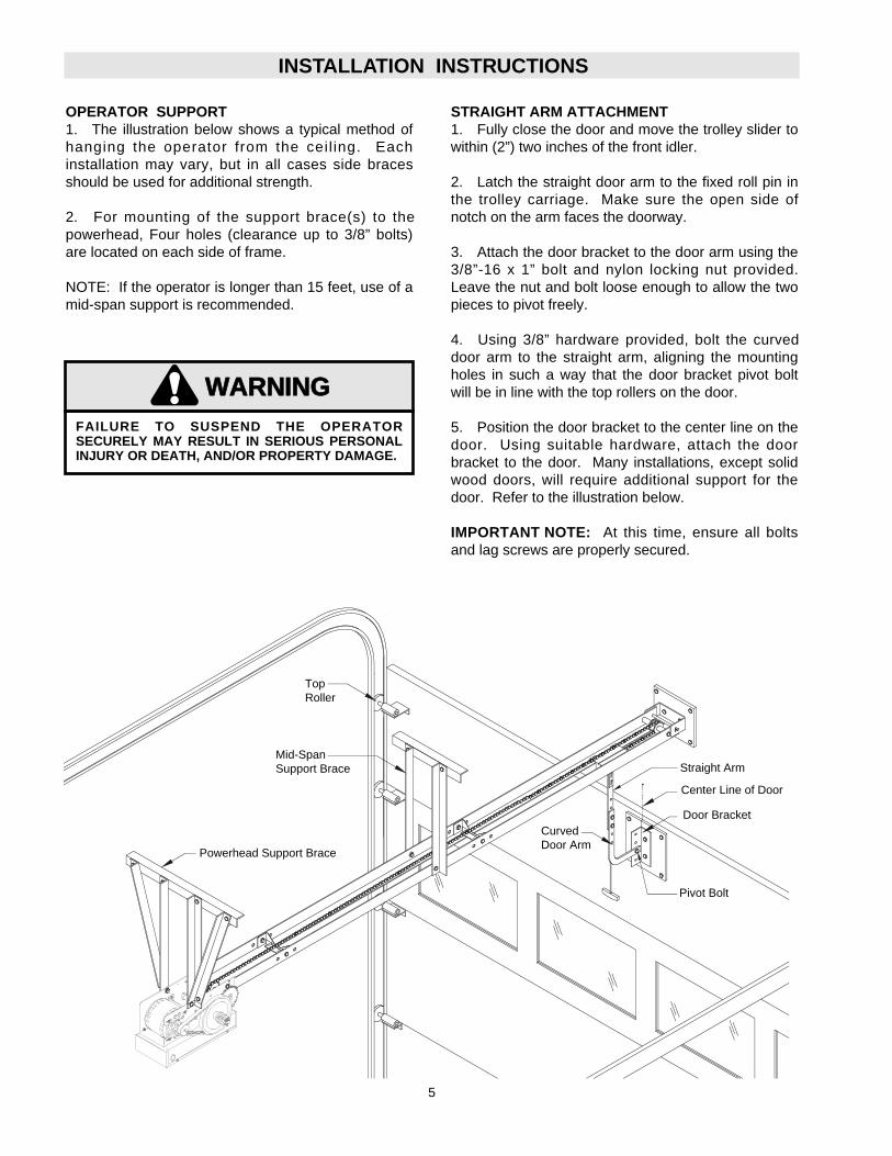
OPERATOR SUPPORT1. The illustration below shows a typical method ofhanging the operator from the ceil ing. Eachinstallation may vary, but in all cases side bracesshould be used for additional strength.
2. For mounting of the support brace(s) to thepowerhead, Four holes (clearance up to 3/8” bolts)are located on each side of frame.
NOTE: If the operator is longer than 15 feet, use of amid-span support is recommended.
STRAIGHT ARM ATTACHMENT1. Fully close the door and move the trolley slider towithin (2”) two inches of the front idler.
2. Latch the straight door arm to the fixed roll pin inthe trolley carriage. Make sure the open side ofnotch on the arm faces the doorway.
3. Attach the door bracket to the door arm using the3/8”-16 x 1” bolt and nylon locking nut provided.Leave the nut and bolt loose enough to allow the twopieces to pivot freely.
4. Using 3/8” hardware provided, bolt the curveddoor arm to the straight arm, aligning the mountingholes in such a way that the door bracket pivot boltwill be in line with the top rollers on the door.
5. Position the door bracket to the center line on thedoor. Using suitable hardware, attach the doorbracket to the door. Many installations, except solidwood doors, will require additional support for thedoor. Refer to the illustration below.
IMPORTANT NOTE: At this time, ensure all boltsand lag screws are properly secured.
Powerhead Support Brace
Mid-SpanSupport Brace
Center Line of Door
Straight Arm
Door BracketCurvedDoor Arm
FAILURE TO SUSPEND THE OPERATORSECURELY MAY RESULT IN SERIOUS PERSONALINJURY OR DEATH, AND/OR PROPERTY DAMAGE.
WARNING
CAUTION
WARNING
WARNING
TopRoller
Pivot Bolt
6
TO AVOID SERIOUS PERSONAL INJURY OR DEATHFROM ELECTROCUTION, DISCONNECT ELECTRICPOWER BEFORE MANUALLY MOVING LIMIT NUTS.
WARNING
CAUTION
WARNING
WARNING
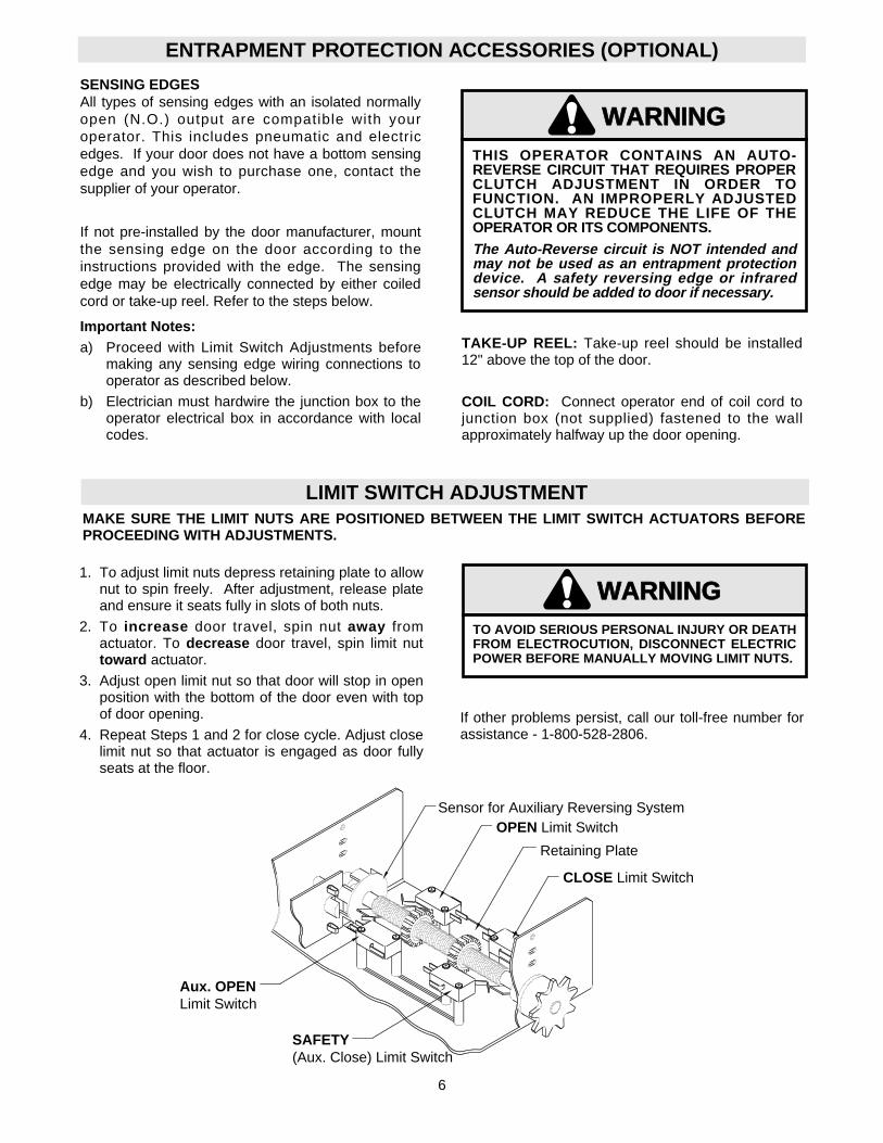
LIMIT SWITCH ADJUSTMENTMAKE SURE THE LIMIT NUTS ARE POSITIONED BETWEEN THE LIMIT SWITCH ACTUATORS BEFOREPROCEEDING WITH ADJUSTMENTS.
SENSING EDGESAll types of sensing edges with an isolated normallyopen (N.O.) output are compatible with youroperator. This includes pneumatic and electricedges. If your door does not have a bottom sensingedge and you wish to purchase one, contact thesupplier of your operator.
If not pre-installed by the door manufacturer, mountthe sensing edge on the door according to theinstructions provided with the edge. The sensingedge may be electrically connected by either coiledcord or take-up reel. Refer to the steps below.
Important Notes:a) Proceed with Limit Switch Adjustments before
making any sensing edge wiring connections tooperator as described below.
b) Electrician must hardwire the junction box to theoperator electrical box in accordance with localcodes.
ENTRAPMENT PROTECTION ACCESSORIES (OPTIONAL)
TAKE-UP REEL: Take-up reel should be installed12" above the top of the door.
COIL CORD: Connect operator end of coil cord tojunction box (not supplied) fastened to the wallapproximately halfway up the door opening.
If other problems persist, call our toll-free number forassistance - 1-800-528-2806.
Retaining Plate
CLOSE Limit Switch
SAFETY(Aux. Close) Limit Switch
OPEN Limit Switch
1. To adjust limit nuts depress retaining plate to allownut to spin freely. After adjustment, release plateand ensure it seats fully in slots of both nuts.
2. To increase door travel, spin nut away fromactuator. To decrease door travel, spin limit nuttoward actuator.
3. Adjust open limit nut so that door will stop in openposition with the bottom of the door even with topof door opening.
4. Repeat Steps 1 and 2 for close cycle. Adjust closelimit nut so that actuator is engaged as door fullyseats at the floor.
Aux. OPENLimit Switch
Sensor for Auxiliary Reversing System
WARNING
CAUTION
WARNING
WARNING
THIS OPERATOR CONTAINS AN AUTO-REVERSE CIRCUIT THAT REQUIRES PROPERCLUTCH ADJUSTMENT IN ORDER TOFUNCTION. AN IMPROPERLY ADJUSTEDCLUTCH MAY REDUCE THE LIFE OF THEOPERATOR OR ITS COMPONENTS.
The Auto-Reverse circuit is NOT intended andmay not be used as an entrapment protectiondevice. A safety reversing edge or infraredsensor should be added to door if necessary.
7
WARNING
CAUTION
WARNING
WARNING
DISCONNECT POWER AT THE FUSE BOX BEFOREPROCEEDING.OPERATOR MUST BE PROPERLY GROUNDED ANDPERMANENTLY WIRED IN ACCORDANCE WITHLOCAL ELECTRICAL CODES. NOTE: THEOPERATOR SHOULD BE ON A SEPARATE FUSEDLINE OF ADEQUATE CAPACITY.ALL ELECTRICAL CONNECTIONS MUST BE MADEBY A QUALIFIED INDIVIDUAL.
WARNING
CAUTION
WARNING
WARNING
TO AVOID DAMAGE TO DOOR AND OPERATOR,MAKE ALL DOOR LOCKS INOPERATIVE. SECURELOCK(S) IN "OPEN" POSITION.IF THE DOOR LOCK NEEDS TO REMAINFUNCTIONAL, INSTALL AN INTERLOCK SWITCH.
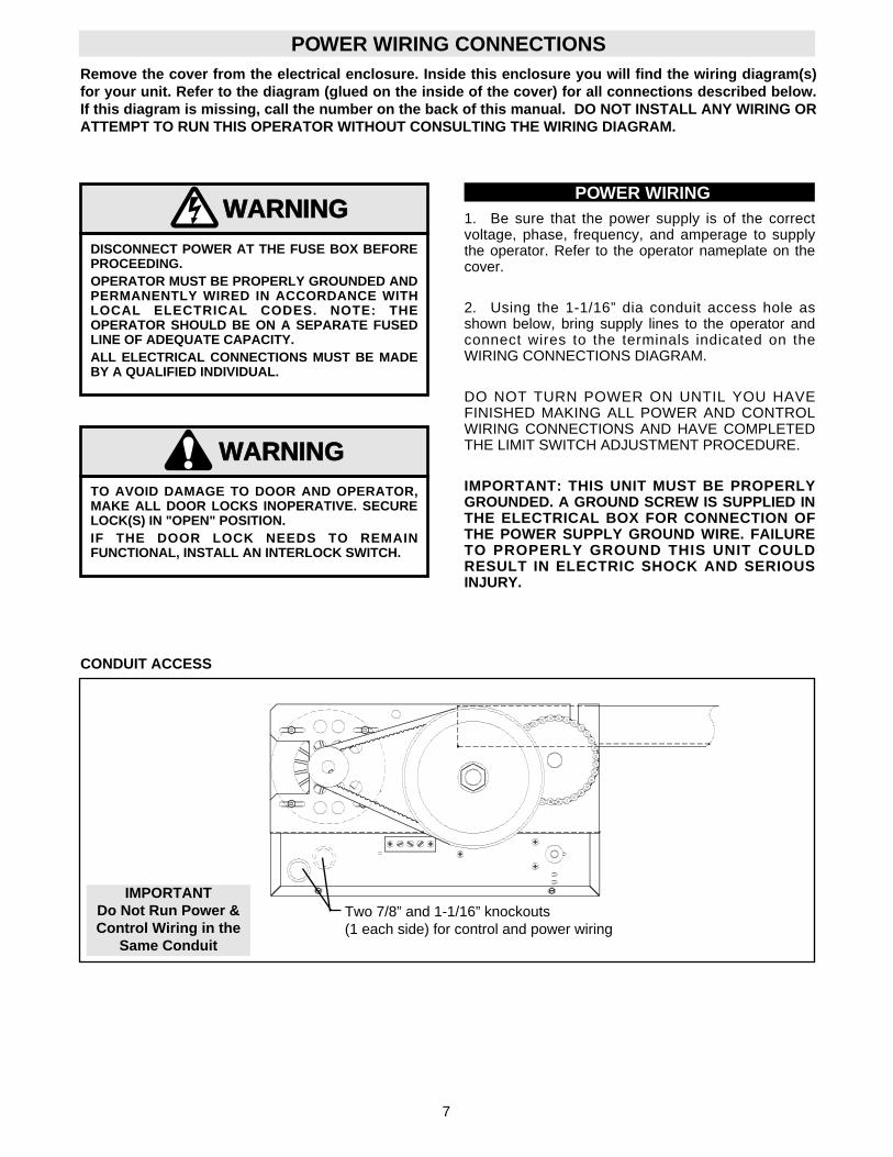
1. Be sure that the power supply is of the correctvoltage, phase, frequency, and amperage to supplythe operator. Refer to the operator nameplate on thecover.
2. Using the 1-1/16” dia conduit access hole asshown below, bring supply lines to the operator andconnect wires to the terminals indicated on theWIRING CONNECTIONS DIAGRAM.
DO NOT TURN POWER ON UNTIL YOU HAVEFINISHED MAKING ALL POWER AND CONTROLWIRING CONNECTIONS AND HAVE COMPLETEDTHE LIMIT SWITCH ADJUSTMENT PROCEDURE.
IMPORTANT: THIS UNIT MUST BE PROPERLYGROUNDED. A GROUND SCREW IS SUPPLIED INTHE ELECTRICAL BOX FOR CONNECTION OFTHE POWER SUPPLY GROUND WIRE. FAILURETO PROPERLY GROUND THIS UNIT COULDRESULT IN ELECTRIC SHOCK AND SERIOUSINJURY.
Remove the cover from the electrical enclosure. Inside this enclosure you will find the wiring diagram(s)for your unit. Refer to the diagram (glued on the inside of the cover) for all connections described below.If this diagram is missing, call the number on the back of this manual. DO NOT INSTALL ANY WIRING ORATTEMPT TO RUN THIS OPERATOR WITHOUT CONSULTING THE WIRING DIAGRAM.
POWER WIRING
POWER WIRING CONNECTIONS
CONDUIT ACCESS
IMPORTANTDo Not Run Power &Control Wiring in the
Same Conduit
Two 7/8” and 1-1/16” knockouts(1 each side) for control and power wiring
8
CONTROL WIRING
Standard C2 or B2 WiringStandard operators are shipped from the factory withjumper set for C2 wiring, which requires constantpressure on button to close the door. If momentarycontact on close direction is desired (B2 wiring) youmust include an entrapment protection device. Seeclose control settings to the right.
WIRINGThis Operator has
Control Wiring.
SUPPLEMENTAL WIRING DIAGRAM(S)
REPLACEMENT WIRING DIAGRAM
Note: Supplemental Wiring Diagrams areto be used in addition to 1753 or 1754.Replacement Wiring Diagram is to be usedin place of 1753 or 1754.
SPECIAL CONTROLWIRING DATA
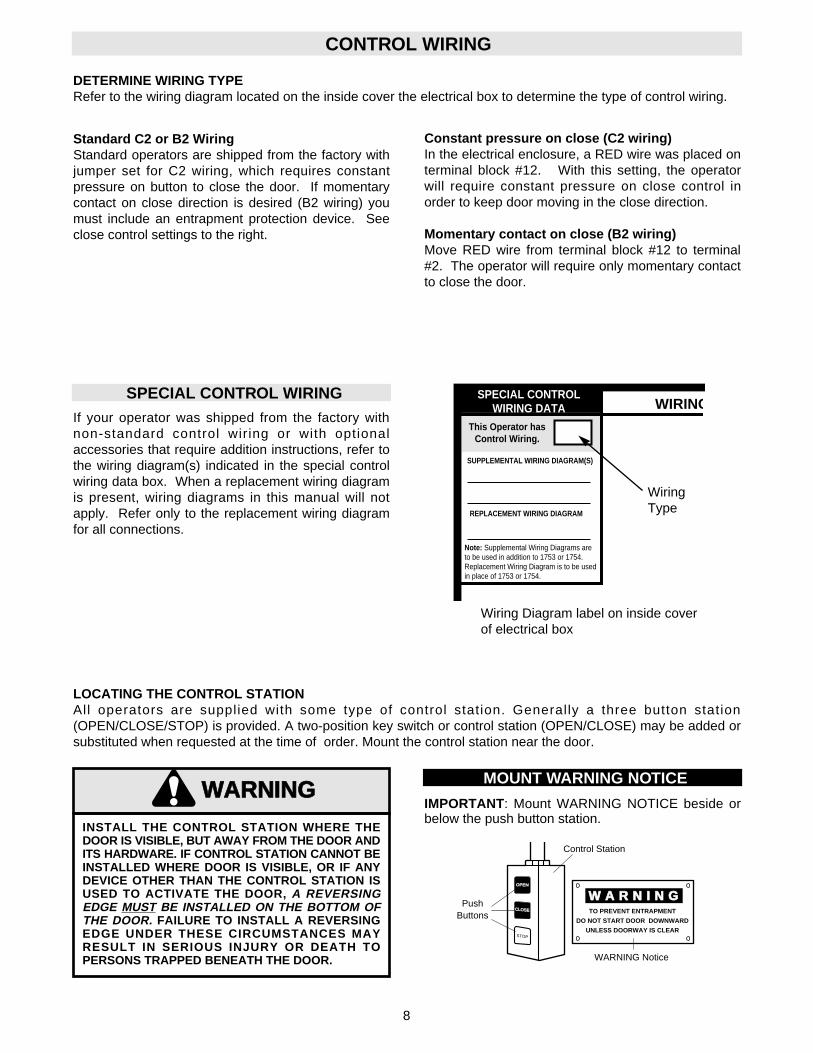
LOCATING THE CONTROL STATIONAll operators are supplied with some type of control station. Generally a three button station(OPEN/CLOSE/STOP) is provided. A two-position key switch or control station (OPEN/CLOSE) may be added orsubstituted when requested at the time of order. Mount the control station near the door.
WARNING
CAUTION
WARNING
WARNING
INSTALL THE CONTROL STATION WHERE THEDOOR IS VISIBLE, BUT AWAY FROM THE DOOR ANDITS HARDWARE. IF CONTROL STATION CANNOT BEINSTALLED WHERE DOOR IS VISIBLE, OR IF ANYDEVICE OTHER THAN THE CONTROL STATION ISUSED TO ACTIVATE THE DOOR, A REVERSINGEDGE MUST BE INSTALLED ON THE BOTTOM OFTHE DOOR. FAILURE TO INSTALL A REVERSINGEDGE UNDER THESE CIRCUMSTANCES MAYRESULT IN SERIOUS INJURY OR DEATH TOPERSONS TRAPPED BENEATH THE DOOR.
W A R N I N GTO PREVENT ENTRAPMENT
DO NOT START DOOR DOWNWARD
UNLESS DOORWAY IS CLEAR
OPENOPEN
CLOSECLOSE
STOP
Control Station
WARNING Notice
PushButtons
IMPORTANT: Mount WARNING NOTICE beside orbelow the push button station.
MOUNT WARNING NOTICE
DETERMINE WIRING TYPERefer to the wiring diagram located on the inside cover the electrical box to determine the type of control wiring.
Wiring Diagram label on inside coverof electrical box
WiringType
SPECIAL CONTROL WIRINGIf your operator was shipped from the factory withnon-standard control wiring or with optionalaccessories that require addition instructions, refer tothe wiring diagram(s) indicated in the special controlwiring data box. When a replacement wiring diagramis present, wiring diagrams in this manual will notapply. Refer only to the replacement wiring diagramfor all connections.
Constant pressure on close (C2 wiring)In the electrical enclosure, a RED wire was placed onterminal block #12. With this setting, the operatorwill require constant pressure on close control inorder to keep door moving in the close direction.
Momentary contact on close (B2 wiring)Move RED wire from terminal block #12 to terminal#2. The operator will require only momentary contactto close the door.
9
CONTROL WIRING
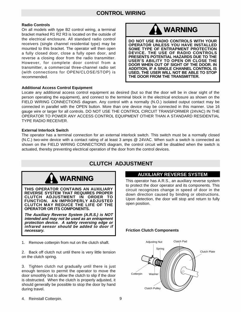
Radio ControlsOn all models with type B2 control wiring, a terminalbracket marked R1 R2 R3 is located on the outside ofthe electrical enclosure. All standard radio controlreceivers (single channel residential type) may bemounted to this bracket. The operator will then opena fully closed door, close a fully open door, andreverse a closing door from the radio transmitter.However, for complete door control from atransmitter, a commercial three-channel radio set(with connections for OPEN/CLOSE/STOP) isrecommended.
Additional Access Control EquipmentLocate any additional access control equipment as desired (but so that the door will be in clear sight of theperson operating the equipment), and connect to the terminal block in the electrical enclosure as shown on theFIELD WIRING CONNECTIONS diagram. Any control with a normally (N.O.) isolated output contact may beconnected in parallel with the OPEN button. More than one device may be connected in this manner. Use 16gauge wire or larger for all controls. DO NOT USE THE CONTROL CIRCUIT TRANSFORMER (24VAC) IN THEOPERATOR TO POWER ANY ACCESS CONTROL EQUIPMENT OTHER THAN A STANDARD RESIDENTIALTYPE RADIO RECEIVER.
External Interlock SwitchThe operator has a terminal connection for an external interlock switch. This switch must be a normally closed(N.C.) two-wire device with a contact rating of at least 3 amps @ 24VAC. When such a switch is connected asshown on the FIELD WIRING CONNECTIONS diagram, the control circuit will be disabled when the switch isactuated, thereby preventing electrical operation of the door from the control devices.
WARNING
CAUTION
WARNING
WARNING
DO NOT USE RADIO CONTROLS WITH YOUROPERATOR UNLESS YOU HAVE INSTALLEDSOME TYPE OF ENTRAPMENT PROTECTIONDEVICE. THE USE OF RADIO CONTROLSPRESENTS POTENTIAL HAZARDS DUE TO THEUSER’S ABILITY TO OPEN OR CLOSE THEDOOR WHEN OUT OF SIGHT OF THE DOOR. INADDITION, IF A SINGLE CHANNEL CONTROL ISUSED, THE USER WILL NOT BE ABLE TO STOPTHE DOOR FROM THE TRANSMITTER.
CLUTCH ADJUSTMENT
1. Remove cotterpin from nut on the clutch shaft.
2. Back off clutch nut until there is very little tensionon the clutch spring.
3. Tighten clutch nut gradually until there is justenough tension to permit the operator to move thedoor smoothly but to allow the clutch to slip if the dooris obstructed. When the clutch is properly adjusted, itshould generally be possible to stop the door by handduring travel.
4. Reinstall Cotterpin.
Cotterpin
Adjusting Nut
Spring
Clutch Pulley
Clutch Plate
Clutch Pad
Washer
AUXILIARY REVERSE SYSTEMThis operator has A.R.S., an auxiliary reverse systemto protect the door operator and its components. Thiscircuit recognizes change in speed of door in thedown direction caused by binding or obstructions.Upon detection, the door will stop and return to fullyopen position.
WARNING
CAUTION
WARNING
WARNING
THIS OPERATOR CONTAINS AN AUXILIARYREVERSE SYSTEM THAT REQUIRES PROPERCLUTCH ADJUSTMENT IN ORDER TOFUNCTION. AN IMPROPERLY ADJUSTEDCLUTCH MAY REDUCE THE LIFE OF THEOPERATOR OR ITS COMPONENTS.
The Auxiliary Reverse System (A.R.S.) is NOTintended and may not be used as an entrapmentprotection device. A safety reversing edge orinfrared sensor should be added to door ifnecessary. Friction Clutch Components
10
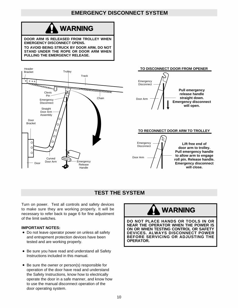
EMERGENCY DISCONNECT SYSTEM
HeaderBracket
StraightDoor ArmAssembly
EmergencyReleaseHandle
DoorBracket
Door
Chain
ClevisPin
Trolley
EmergencyDisconnect
Track
Pull emergencyrelease handlestraight down.
Emergency disconnectwill open.
EmergencyDisconnect
CurvedDoor Arm
Door Arm
Lift free end ofdoor arm to trolley.
Pull emergency handleto allow arm to engage
roll pin. Release handle.Emergency disconnect
will close.
EmergencyDisconnect
Door ArmNOTICE
TO DISCONNECT DOOR FROM OPENER
TO RECONNECT DOOR ARM TO TROLLEY
DOOR ARM IS RELEASED FROM TROLLEY WHENEMERGENCY DISCONNECT OPENS.TO AVOID BEING STRUCK BY DOOR ARM, DO NOTSTAND UNDER THE ROPE OR DOOR ARM WHENPULLING THE EMERGENCY RELEASE.
WARNING
CAUTION
WARNING
WARNING
TEST THE SYSTEM
Turn on power. Test all controls and safety devicesto make sure they are working properly. It will benecessary to refer back to page 6 for fine adjustmentof the limit switches.
IMPORTANT NOTES:Do not leave operator power on unless all safety and entrapment protection devices have been tested and are working properly.
Be sure you have read and understand all Safety Instructions included in this manual.
Be sure the owner or person(s) responsible for operation of the door have read and understand the Safety Instructions, know how to electrically operate the door in a safe manner, and know how to use the manual disconnect operation of the door operating system.
WARNING
CAUTION
WARNING
WARNING
DO NOT PLACE HANDS OR TOOLS IN ORNEAR THE OPERATOR WHEN THE POWER ISON OR WHEN TESTING CONTROL OR SAFETYDEVICES. ALWAYS DISCONNECT POWERBEFORE SERVICING OR ADJUSTING THEOPERATOR.
11
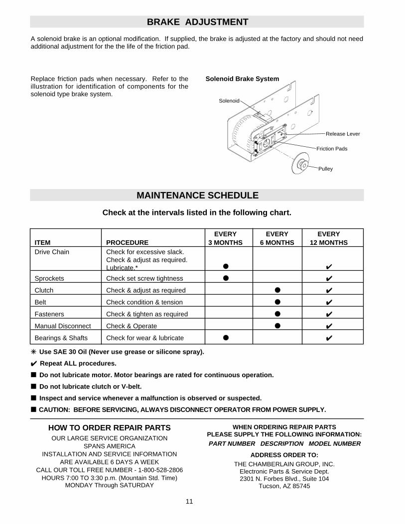
BRAKE ADJUSTMENT
✳✳ Use SAE 30 Oil (Never use grease or silicone spray).
✔✔ Repeat ALL procedures.
■■ Do not lubricate motor. Motor bearings are rated for continuous operation.
■■ Do not lubricate clutch or V-belt.
■■ Inspect and service whenever a malfunction is observed or suspected.
■■ CAUTION: BEFORE SERVICING, ALWAYS DISCONNECT OPERATOR FROM POWER SUPPLY.
Check at the intervals listed in the following chart.
HOW TO ORDER REPAIR PARTSOUR LARGE SERVICE ORGANIZATION
SPANS AMERICAINSTALLATION AND SERVICE INFORMATION
ARE AVAILABLE 6 DAYS A WEEKCALL OUR TOLL FREE NUMBER - 1-800-528-2806
HOURS 7:00 TO 3:30 p.m. (Mountain Std. Time)MONDAY Through SATURDAY
WHEN ORDERING REPAIR PARTSPLEASE SUPPLY THE FOLLOWING INFORMATION:PART NUMBER DESCRIPTION MODEL NUMBER
ADDRESS ORDER TO:THE CHAMBERLAIN GROUP, INC.
Electronic Parts & Service Dept.2301 N. Forbes Blvd., Suite 104
Tucson, AZ 85745
EVERY EVERY EVERYITEM PROCEDURE 3 MONTHS 6 MONTHS 12 MONTHSDrive Chain Check for excessive slack.
Check & adjust as required.Lubricate.* ● ✔
Sprockets Check set screw tightness ●● ✔✔
Clutch Check & adjust as required ●● ✔✔
Belt Check condition & tension ●● ✔✔
Fasteners Check & tighten as required ●● ✔✔
Manual Disconnect Check & Operate ●● ✔✔
Bearings & Shafts Check for wear & lubricate ●● ✔✔
MAINTENANCE SCHEDULE
A solenoid brake is an optional modification. If supplied, the brake is adjusted at the factory and should not needadditional adjustment for the the life of the friction pad.
Replace friction pads when necessary. Refer to theillustration for identification of components for thesolenoid type brake system.
Friction Pads
Release Lever
Pulley
Solenoid
Solenoid Brake System
(OPTIONAL)BIMETAL
CLOSE-A
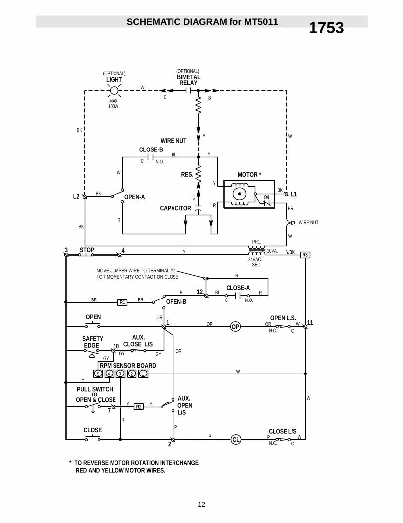
RED AND YELLOW MOTOR WIRES.* TO REVERSE MOTOR ROTATION INTERCHANGE
PULL SWITCH
OPEN & CLOSE
CLOSE
TO
SAFETY EDGE
OPEN
BR
2
P
7Y
10GY
Y
AUX.
R1 BR
1
ORGY
OPENAUX.
L/S
OPEN-B
BL
OR
12BL
C
(OPTIONAL)
CLOSE L/S
BK
3 STOP
L2 BK
BK
4
R
OPEN-A
W
C
CAPACITOR
Y
N.O.
100WMAX.
WLIGHT RELAY
C
SEC.
OPEN L.S.
CLOSE L/SP PCL
OR
R
N.O.
R
OROPN.C. C
W
W
W
11
BR
L1
MOTOR *
R
Y
10VA.
PR1.
24VAC.Y/BK
W
O/LBK
A
B
W
WIRE NUT
R3
R2
34 2 15
GY
Y
R
WRPM SENSOR BOARD
N.C. C
MOVE JUMPER WIRE TO TERMINAL #2FOR MOMENTARY CONTACT ON CLOSE
Y
WIRE NUTCLOSE-B
RES.
BL
Y
12
SCHEMATIC DIAGRAM for MT5011 1753
13
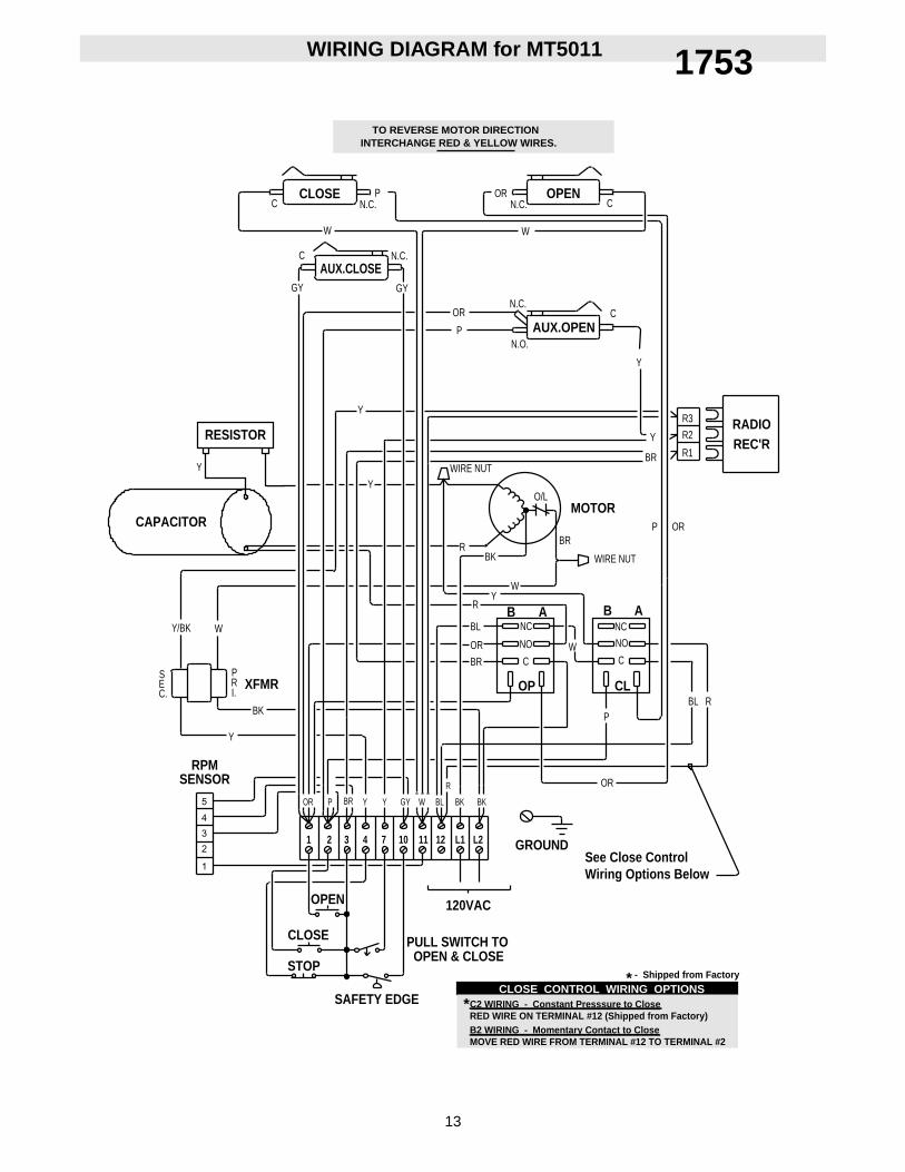
WIRING DIAGRAM for MT5011
S
C.E
P
I.R
Y/BK W
CAPACITOR
OPEN
STOP
CLOSE
1 2 3 4
PULL SWITCH TO
SAFETY EDGE
OPEN & CLOSE
12107 11
120VAC
L2L1
OR P YBR
BK
Y
BLGYY W BKBK
GROUND
OR
OP
P
CLBL R
WY
BR
OR
BL
RB
BKR
Y
Y
NO
CW
ANC
NO
C
NCB A
WIRE NUT
Y
O/LMOTOR
BR
Y
R1
R3
R2
N.C.
N.O.
N.C.GY
C
W
GY
P
OR
N.C.
N.C.CCLOSE P OR
C
W
OPENC
3
4
5
2
1
RADIOREC'R
RPMSENSOR
XFMR
AUX.CLOSE
AUX.OPEN
R
BRORP
INTERCHANGE RED & YELLOW WIRES.TO REVERSE MOTOR DIRECTION
C2 WIRING - Constant Presssure to CloseRED WIRE ON TERMINAL #12 (Shipped from Factory)B2 WIRING - Momentary Contact to CloseMOVE RED WIRE FROM TERMINAL #12 TO TERMINAL #2
*CLOSE CONTROL WIRING OPTIONS
- Shipped from Factory
*
See Close ControlWiring Options Below
RESISTOR
NUTWIREY
1753
(OPTIONAL)BIMETAL
CLOSE-A
RED AND YELLOW MOTOR WIRES.* TO REVERSE MOTOR ROTATION INTERCHANGE
PULL SWITCH
OPEN & CLOSE
CLOSE
TO
SAFETY EDGE
OPEN
BR
2
P
7Y
10GY
Y
AUX.
R1 BR
1
ORGY
OPENAUX.
L/S
OPEN-B
BL
OR
12BL
C
(OPTIONAL)
CLOSE L/S
BK
3 STOP
L2 BK
BK
CLOSE-B
4
R
OPEN-A
W
C
CAPACITOR
Y
N.O.
BL
100WMAX.
WLIGHT RELAY
C
SEC.
OPEN L.S.
CLOSE L/SP PCL
OR
R
N.O.
R
OROPN.C. C
W
W
W
11
BR
L1
MOTOR *
RY
10VA.
PR1.
24VAC. Y
W
O/L BK
A
B
W
WIRE NUT
R3
R2
34 2 15
GY
W
R
Y
A.R.S. BOARD(When Present)
N.C. C
MOVE JUMPER WIRE TO TERMINAL #2FOR MOMENTARY CONTACT ON CLOSE
Y
HAND CHAININTERLOCK SW.
(WHEN PRESENT)
BRAKE SOLENOID
CLOSE-C
OPEN-C BL/BK
RES.
14
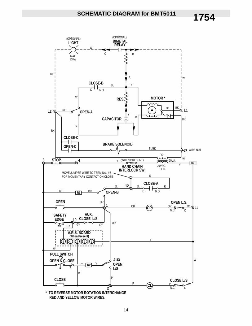
SCHEMATIC DIAGRAM for BMT5011 1754
15
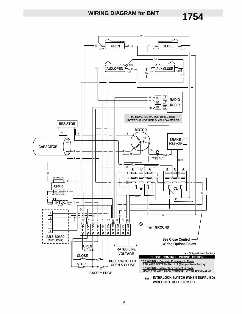
WIRING DIAGRAM for BMT
SECONDARY
PRIMARY
W
CAPACITOR
OPEN
STOP
CLOSE
1 2 3 4
PULL SWITCH TO
SAFETY EDGE
OPEN & CLOSE
12107 11
RATED LINEVOLTAGE
L2L1
OR P YBR
BK
Y
BLGYY BKBK
GROUND
OR
OP
P
CLBL R
WBL
BR
OR
BL
R
BKR
Y
Y
W
WIRE NUT
Y
O/L
MOTOR
BR R1
R3
R2
GY
W CLOSEPOROPEN
3
4
5
2
1
RADIOREC'R
XFMR
AUX.CLOSEAUX.OPEN
R
BR
P
NO
C
NC
B A
NO
C
NC
C
NO
C
NC
B A
NO
C
NC
C
BRAKESOLENOID
N.O.COMINTLK.
Y
- INTERLOCK SWITCH (WHEN SUPPLIED) WIRED N.O. HELD CLOSED.**
**
INTERCHANGE RED & YELLOW WIRES.TO REVERSE MOTOR DIRECTION
C2 WIRING - Constant Presssure to CloseRED WIRE ON TERMINAL #12 (Shipped from Factory)B2 WIRING - Momentary Contact to CloseMOVE RED WIRE FROM TERMINAL #12 TO TERMINAL #2
*CLOSE CONTROL WIRING OPTIONS
- Shipped from Factory
*
See Close ControlWiring Options Below
W
BL/BK
BL/BK
BL/BK
A.R.S. BOARD(When Present)
Y
W
N.C.
COM
COM
N.C.
N.O. GYN.C.
OR
W
COM
P
R
Y
R
RESISTOR
Y
GY
1754
16
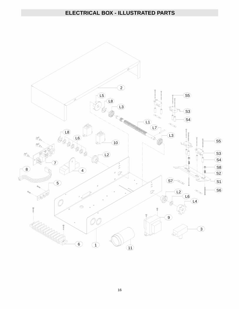
ELECTRICAL BOX - ILLUSTRATED PARTS
2
L3
L5
L7L8
S3
L1
S2
S1
L6L2
S75
111
S6
S4
S8
6
S5
S4
S3
S5
L8
L3
7
L4
10
L2
9
L6
4
3
8
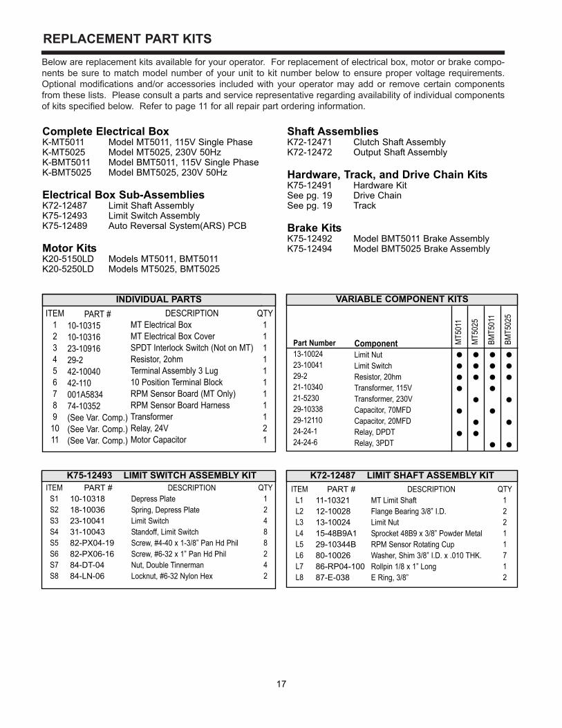
REPLACEMENT PART KITSBelow are replacement kits available for your operator. For replacement of electrical box, motor or brake compo-nents be sure to match model number of your unit to kit number below to ensure proper voltage requirements.Optional modifications and/or accessories included with your operator may add or remove certain componentsfrom these lists. Please consult a parts and service representative regarding availability of individual componentsof kits specified below. Refer to page 11 for all repair part ordering information.
Complete Electrical Box K-MT5011 Model MT5011, 115V Single PhaseK-MT5025 Model MT5025, 230V 50HzK-BMT5011 Model BMT5011, 115V Single PhaseK-BMT5025 Model BMT5025, 230V 50Hz
Electrical Box Sub-AssembliesK72-12487 Limit Shaft AssemblyK75-12493 Limit Switch AssemblyK75-12489 Auto Reversal System(ARS) PCB
Motor KitsK20-5150LD Models MT5011, BMT5011K20-5250LD Models MT5025, BMT5025
Shaft AssembliesK72-12471 Clutch Shaft AssemblyK72-12472 Output Shaft Assembly
Hardware, Track, and Drive Chain KitsK75-12491 Hardware KitSee pg. 19 Drive ChainSee pg. 19 Track
Brake KitsK75-12492 Model BMT5011 Brake AssemblyK75-12494 Model BMT5025 Brake Assembly
VARIABLE COMPONENT KITS
Part Number13-1002423-1004129-221-1034021-523029-1033829-1211024-24-124-24-6
ComponentLimit NutLimit SwitchResistor, 20hmTransformer, 115V Transformer, 230VCapacitor, 70MFDCapacitor, 20MFD Relay, DPDTRelay, 3PDT
MT5
011
MT5
025
BMT5
011
BMT5
025
QTY12488242
QTY12211712
K72-12487 LIMIT SHAFT ASSEMBLY KITITEM
L1L2L3L4L5L6L7L8
DESCRIPTIONMT Limit ShaftFlange Bearing 3/8” I.D.Limit NutSprocket 48B9 x 3/8” Powder MetalRPM Sensor Rotating CupWasher, Shim 3/8” I.D. x .010 THK.Rollpin 1/8 x 1” LongE Ring, 3/8”
K75-12493 LIMIT SWITCH ASSEMBLY KITPART #
11-1032112-1002813-1002415-48B9A129-10344B80-1002686-RP04-10087-E-038
ITEMS1S2S3S4S5S6S7S8
DESCRIPTIONDepress PlateSpring, Depress PlateLimit SwitchStandoff, Limit SwitchScrew, #4-40 x 1-3/8” Pan Hd PhilScrew, #6-32 x 1” Pan Hd PhilNut, Double TinnermanLocknut, #6-32 Nylon Hex
PART #10-1031818-1003623-1004131-1004382-PX04-1982-PX06-1684-DT-0484-LN-06
ITEM123456789
1011
PART #10-1031510-1031623-1091629-242-1004042-110001A583474-10352(See Var. Comp.)(See Var. Comp.)(See Var. Comp.)
DESCRIPTIONMT Electrical BoxMT Electrical Box CoverSPDT Interlock Switch (Not on MT)Resistor, 2ohmTerminal Assembly 3 Lug10 Position Terminal BlockRPM Sensor Board (MT Only)RPM Sensor Board HarnessTransformerRelay, 24VMotor Capacitor
QTY11111111121
INDIVIDUAL PARTS
17
18
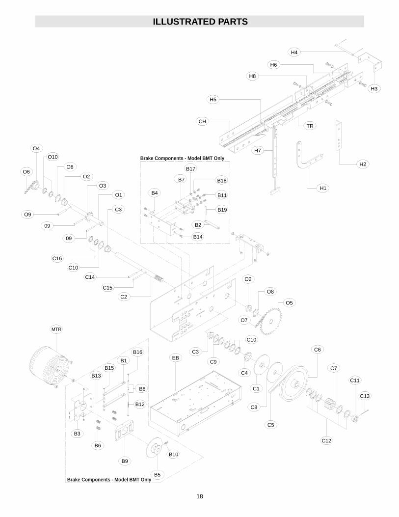
ILLUSTRATED PARTS
O4
O10
O8O6
O2
O9
O3
O1
C3
B14
B4
B7
B17
B11
B18
B19
B2
CH
H5
H8
H6
H4
H3
TR
H2
H1
H7
09
09
C16
C10
C14
C15
C2
O2
O8
O5
O7
C10
C6
C7
C11
C13
C12
C5
C8
C4
C9
C3EB
B16
B1
B8
B15
MTR
B13
B10
B12
B5
B9
B6
C1
B3
Brake Components - Model BMT Only
Brake Components - Model BMT Only
19
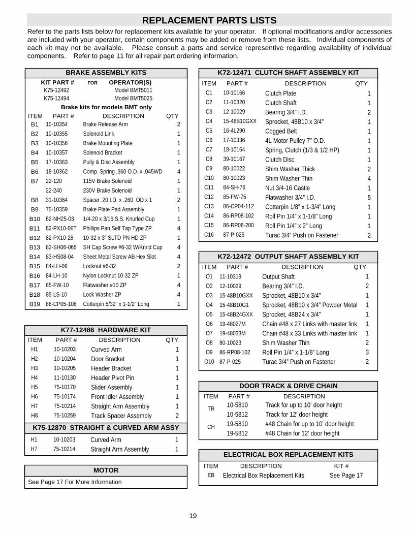
REPLACEMENT PARTS LISTSRefer to the parts lists below for replacement kits available for your operator. If optional modifications and/or accessoriesare included with your operator, certain components may be added or remove from these lists. Individual components ofeach kit may not be available. Please consult a parts and service representive regarding availability of individualcomponents. Refer to page 11 for all repair part ordering information.
K72-12471 CLUTCH SHAFT ASSEMBLY KIT
ITEM PART # DESCRIPTION QTY
C1
C2
C3
C4
C5
C6
C7
C8
C9
C10
C11
C12
C13
C14
C15
C16
Clutch PlateClutch ShaftBearing 3/4” I.D.Sprocket, 48B10 x 3/4”Cogged Belt4L Motor Pulley 7” O.D.Spring, Clutch (1/3 & 1/2 HP)Clutch DiscShim Washer ThickShim Washer ThinNut 3/4-16 CastleFlatwasher 3/4” I.D.Cotterpin 1/8” x 1-3/4” LongRoll Pin 1/4” x 1-1/8” LongRoll Pin 1/4” x 2” LongTurac 3/4” Push on Fastener
1121111124151112
K72-12472 OUTPUT SHAFT ASSEMBLY KIT
ITEM PART # DESCRIPTION QTY
O1
O2
O3
O4
O5
O6
O7
O8
O9
O10
Output ShaftBearing 3/4” I.D.Sprocket, 48B10 x 3/4”Sprocket, 48B10 x 3/4” Powder MetalSprocket, 48B24 x 3/4”Chain #48 x 27 Links with master linkChain #48 x 33 Links with master linkShim Washer ThinRoll Pin 1/4” x 1-1/8” LongTurac 3/4” Push on Fastener
1211111232
K77-12486 HARDWARE KITITEM PART # DESCRIPTION QTY
H1
H2
H3
H4
H5
H6
H7
H8
Curved ArmDoor BracketHeader BracketHeader Pivot PinSlider AssemblyFront Idler AssemblyStraight Arm AssemblyTrack Spacer Assembly
11111112
Brake kits for models BMT only
11-10319
12-10029
15-48B10GXX
15-48B10G1
15-48B24GXX
19-48027M
19-48033M
80-10023
86-RP08-102
87-P-025
10-10203
10-10204
10-10205
11-10130
75-10170
75-10174
75-10214
75-10259
10-10166
11-10320
12-10029
15-48B10GXX
16-4L290
17-10336
18-10164
39-10167
80-10022
80-10023
84-SH-76
85-FW-75
86-CP04-112
86-RP08-102
86-RP08-200
87-P-025
K75-12870 STRAIGHT & CURVED ARM ASSY
H1
H7
Curved ArmStraight Arm Assembly
11
10-10203
75-10214
ITEM PART # DESCRIPTION QTYB1
B2
B3
B4
B5
B6
B7
B8
B9
B10
B11
B12
B13
B14
B15
B16
B17
B18
B19
Brake Release Arm
Solenoid Link
Brake Mounting Plate
Solenoid Bracket
Pully & Disc Assembly
Comp. Spring .360 O.D. x .045WD
115V Brake Solenoid
230V Brake Solenoid
Spacer .20 I.D. x .260 OD x 1
Brake Plate Pad Assembly
1/4-20 x 3/16 S.S. Knurled Cup
Phillips Pan Self Tap Type ZP
10-32 x 3” SLTD PN HD ZP
SH Cap Screw #6-32 W/Knrld Cup
Sheet Metal Screw AB Hex Slot
Locknut #6-32
Nylon Locknut 10-32 ZP
Flatwasher #10 ZP
Lock Washer ZP
Cotterpin 5/32” x 1-1/2” Long
2
1
1
1
1
4
1
1
2
1
1
4
1
4
4
2
1
4
4
1
10-10354
10-10355
10-10356
10-10357
17-10363
18-10362
22-120
22-240
31-10364
75-10359
82-NH25-03
82-PX10-06T
82-PX10-28
82-SH06-065
83-HS08-04
84-LH-06
84-LH-10
85-FW-10
85-LS-10
86-CP05-108
BRAKE ASSEMBLY KITS
Model BMT5011Model BMT5025
K75-12492K75-12494
KIT PART # FOR OPERATOR(S)
DOOR TRACK & DRIVE CHAIN
ITEM PART # DESCRIPTION
TR
CH
10-5810 Track for up to 10’ door height10-5812 Track for 12’ door height19-5810 #48 Chain for up to 10’ door height19-5812 #48 Chain for 12’ door height
ELECTRICAL BOX REPLACEMENT KITS
ITEM DESCRIPTION KIT #
EB Electrical Box Replacement Kits See Page 17MOTOR
See Page 17 For More Information
OPEN TIMER TO CLOSE
3 BUTTON STATION or 3 POSITION KEYSWITCH w/ SPRING RETURN TO CENTER AND STOP BUTTON
2 OR MORE KEY LOCKOUT
R1 R2 R3
1 2 3 4
Stop
Close
Open
Stop
Close
Open
1 2 3 4
Stop
Close
Open
2 BUTTON STATION or 3 POSITION KEYSWITCH w/ SPRING RETURN TO CENTER
STANDARD
1 2 4
Close
Open
2 OR MORE1 2 4
Close
Open
Close
Open
STOP
3 4
RADIO CONTROL
RESIDENTIAL RADIO CONTROLS1 BUTTON STATION or ANY AUXILIARY DEVICE
EXTERNAL INTERLOCK
3 10
EXT.INTERLOCK
STANDARD
1 2 3 4
Stop
Close
Open
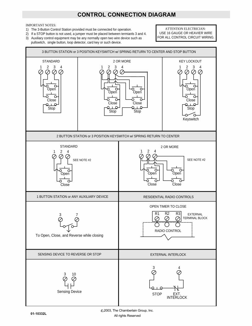
IMPORTANT NOTES:1) The 3-Button Control Station provided must be connected for operation.2) If a STOP button is not used, a jumper must be placed between termianls 3 and 4.3) Auxiliary control equipment may be any normally open two wire device such as pullswitch, single button, loop detector, card key or such device.
Keyswitch
Sensing Device
EXTERNALTERMINAL BLOCK
SENSING DEVICE TO REVERSE OR STOP
ATTENTION ELECTRICIAN:USE 16 GAUGE OR HEAVIER WIRE
FOR ALL CONTROL CIRCUIT WIRING.
SEE NOTE #2SEE NOTE #2
3 7
To Open, Close, and Reverse while closing
CONTROL CONNECTION DIAGRAM
c 2003, The Chamberlain Group, Inc.All rights Reserved01-10332L
Recommended