Overview of Offshore Well Completions
Dennis McDaniel – Offshore Operators Committee
NASEM Workshop: Offshore Well Completion and Stimulation using Hydraulic Fracturing and Other Technologies
October 2, 2017 Washington, D.C.
Contributors
• Numerous Members and Associate Members of the Offshore Operators Committee contributed many staff-hours to help develop this presentation
The information contained in this document is reflective of current industry practices (as of 2017) only. Future technical developments and methods may change
Overview
• Offshore Well Completions • Basics • Techniques Utilized
• Sand Control Completion Operations • Comparison of Offshore and Onshore Well Completions • Summary
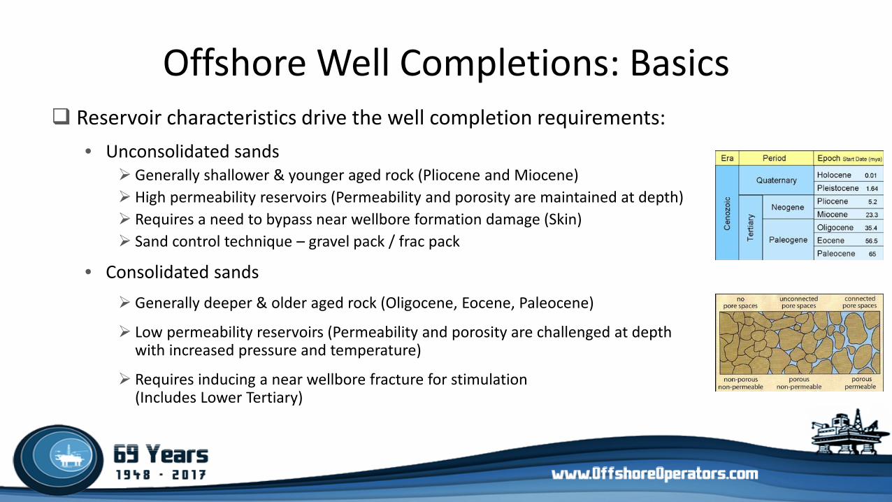
Offshore Well Completions: Basics Reservoir characteristics drive the well completion requirements:
• Unconsolidated sands Generally shallower & younger aged rock (Pliocene and Miocene) High permeability reservoirs (Permeability and porosity are maintained at depth) Requires a need to bypass near wellbore formation damage (Skin) Sand control technique – gravel pack / frac pack
• Consolidated sands Generally deeper & older aged rock (Oligocene, Eocene, Paleocene)
Low permeability reservoirs (Permeability and porosity are challenged at depth with increased pressure and temperature)
Requires inducing a near wellbore fracture for stimulation (Includes Lower Tertiary)
Offshore Well Completions: Techniques Utilized Primary driver of offshore completion design is sand control with an
extensive history of successful application in the Gulf of Mexico: • Gravel / Annular Pack
Proppant filled perforation tunnels and screen x casing annular area
• Frac Pack Induces near wellbore fracture geometry that is filled with proppant to bypass near wellbore
damage and extend the proppant pack a further distance from the wellbore
• Hydraulic Fracturing Technique used for reservoir stimulation in consolidated reservoirs
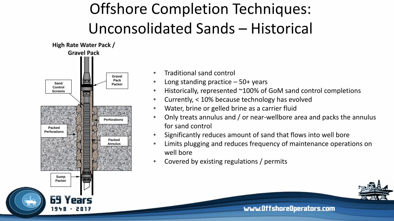
Offshore Completion Techniques: Unconsolidated Sands – Historical
• Traditional sand control • Long standing practice – 50+ years • Historically, represented ~100% of GoM sand control completions • Currently, < 10% because technology has evolved • Water, brine or gelled brine as a carrier fluid • Only treats annulus and / or near-wellbore area and packs the annulus
for sand control • Significantly reduces amount of sand that flows into well bore • Limits plugging and reduces frequency of maintenance operations on
well bore • Covered by existing regulations / permits
Gravel Pack
Packer
Sump Packer
Perforations Packed
Perforations
Packed Annulus
Sand Control Screens
High Rate Water Pack / Gravel Pack
Offshore Completion Techniques: Unconsolidated Sands – Current
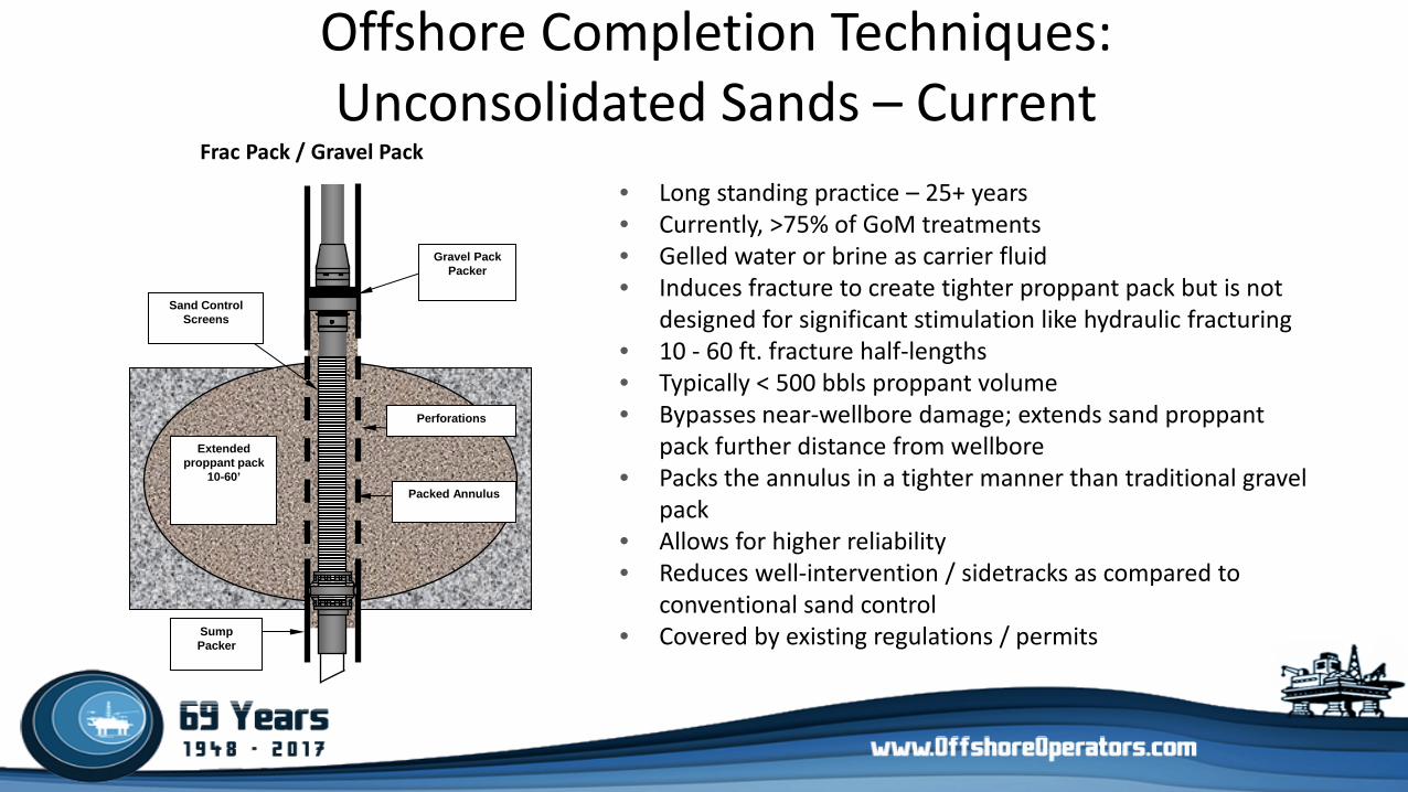
• Long standing practice – 25+ years • Currently, >75% of GoM treatments • Gelled water or brine as carrier fluid • Induces fracture to create tighter proppant pack but is not
designed for significant stimulation like hydraulic fracturing • 10 - 60 ft. fracture half-lengths • Typically < 500 bbls proppant volume • Bypasses near-wellbore damage; extends sand proppant
pack further distance from wellbore • Packs the annulus in a tighter manner than traditional gravel
pack • Allows for higher reliability • Reduces well-intervention / sidetracks as compared to
conventional sand control • Covered by existing regulations / permits
Sump Packer
Extended proppant pack
10-60’ Packed Annulus
Perforations
Sand Control Screens
Gravel Pack Packer
Frac Pack / Gravel Pack
Offshore Completion Techniques: Consolidated Sands – Current
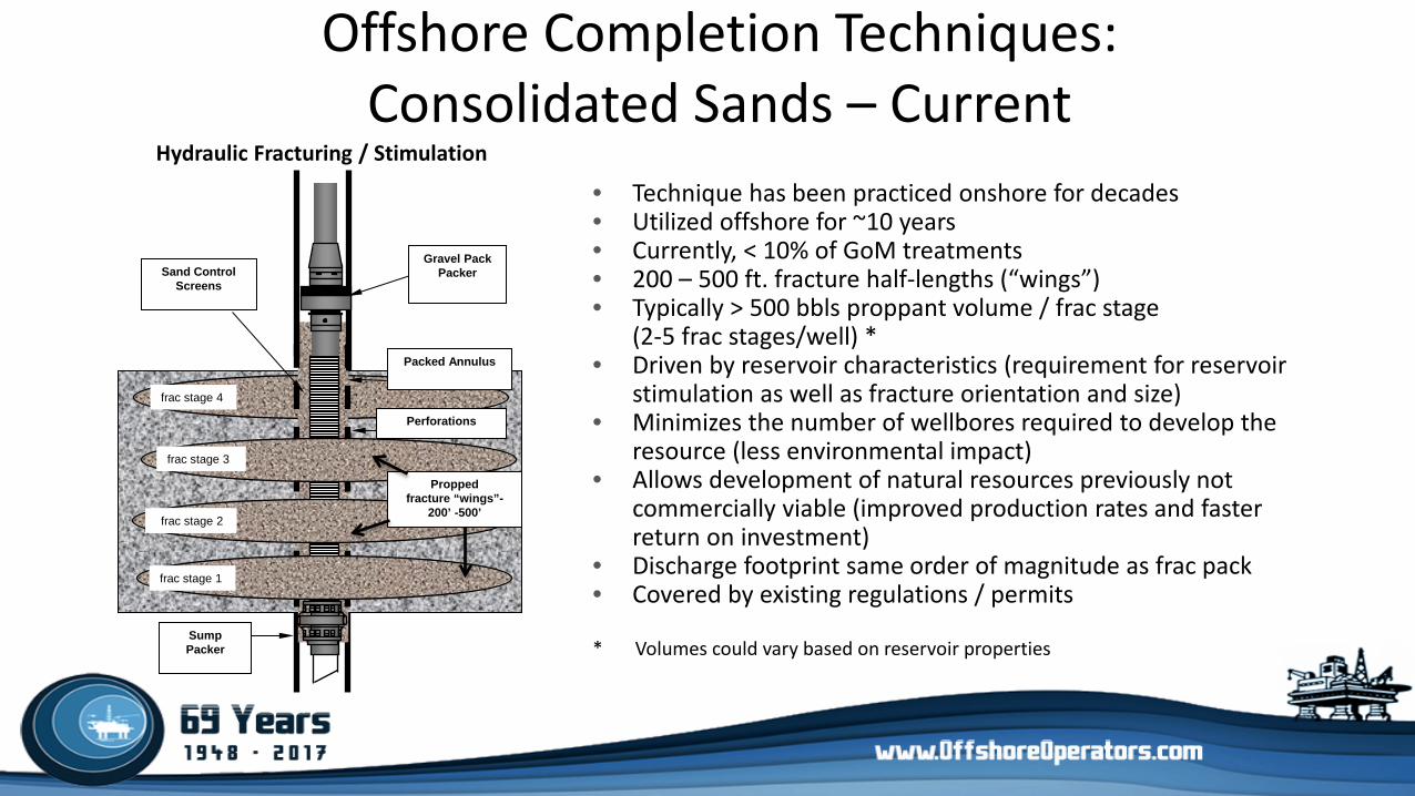
• Technique has been practiced onshore for decades • Utilized offshore for ~10 years • Currently, < 10% of GoM treatments • 200 – 500 ft. fracture half-lengths (“wings”) • Typically > 500 bbls proppant volume / frac stage
(2-5 frac stages/well) * • Driven by reservoir characteristics (requirement for reservoir
stimulation as well as fracture orientation and size) • Minimizes the number of wellbores required to develop the
resource (less environmental impact) • Allows development of natural resources previously not
commercially viable (improved production rates and faster return on investment)
• Discharge footprint same order of magnitude as frac pack • Covered by existing regulations / permits * Volumes could vary based on reservoir properties
Sump Packer
Packed Annulus
Perforations
Sand Control Screens
Gravel Pack Packer
Propped fracture “wings”-
200’ -500’
Hydraulic Fracturing / Stimulation
frac stage 1
frac stage 2 frac stage 2
frac stage 3
frac stage 4
Sand Control Completion Operations: General Step-by-Step
First, gel and water are blended together • Typically use quality guar, starch or cellulose gel
many gel powders are found in commercial foods & commodities (ice cream, gravy, ketchup, cosmetics, etc.)
this mixture is referred to as frac gel and is viscous like vegetable oil
Second, proppants are blended into the gel in a large blender that mixes the ingredients • Additives include cross-linkers, surfactants and buffers
Finally, the resulting mixture becomes a cross-linked fluid that behaves like Jello ®
Sand Control Completion Operations: General Step-by-Step (cont’d)
Mixture is pumped downhole, where the gelatin-like fluid transports proppant into the created fracture
Fracture becomes filled with proppant, and pumping is ceased Additives in the fluid system break the cross-link, turning the Jello ® like fluid back
into a liquid Fracture closes on proppant trapping it in place, and fluid flows out of the well
during production
Sand Control Completion Operations: General Step-by-Step (cont’d)
The proppant provides a highly conductive channel to allow reservoir fluids to move easily toward the wellbore, which enhances the well productivity
Routinely utilize mini-fracs (gelled fluid without proppant) to gain information about the reservoir to help design the main treatment • Mini-fracs are followed by mini-frac flush fluid to prepare well for main treatment
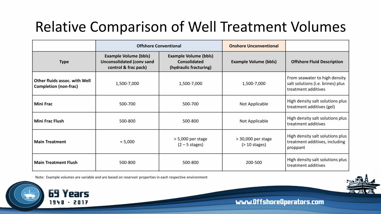
Relative Comparison of Well Treatment Volumes Offshore Conventional Onshore Unconventional
Type Example Volume (bbls)
Unconsolidated (conv sand control & frac pack)
Example Volume (bbls) Consolidated
(hydraulic fracturing) Example Volume (bbls) Offshore Fluid Description
Other fluids assoc. with Well Completion (non-frac) 1,500-7,000 1,500-7,000 1,500-7,000
From seawater to high density salt solutions (i.e. brines) plus treatment additives
Mini Frac 500-700 500-700 Not Applicable High density salt solutions plus treatment additives (gel)
Mini Frac Flush 500-800 500-800 Not Applicable High density salt solutions plus treatment additives
Main Treatment < 5,000 > 5,000 per stage (2 – 5 stages)
> 30,000 per stage (> 10 stages)
High density salt solutions plus treatment additives, including proppant
Main Treatment Flush 500-800 500-800 200-500 High density salt solutions plus treatment additives
Note: Example volumes are variable and are based on reservoir properties in each respective environment
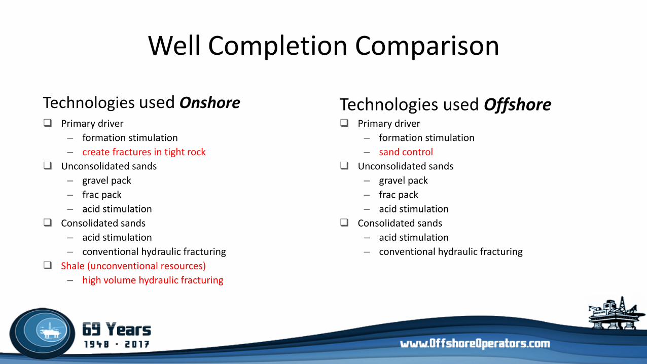
Well Completion Comparison
Primary driver – formation stimulation – create fractures in tight rock
Unconsolidated sands – gravel pack – frac pack – acid stimulation
Consolidated sands – acid stimulation – conventional hydraulic fracturing
Shale (unconventional resources) – high volume hydraulic fracturing
Primary driver – formation stimulation – sand control
Unconsolidated sands – gravel pack – frac pack – acid stimulation
Consolidated sands – acid stimulation – conventional hydraulic fracturing
Technologies used Onshore Technologies used Offshore
Offshore Well Completions: Summary
• Primary driver of offshore completion design is sand control with an extensive history of successful application in the GoM
• Offshore completion activities are covered extensively by existing regulations – both operational & environmental
• High volume hydraulic fracturing of unconventional formations is not occurring offshore GoM
• Concerns for implications to drinking water aquifers is not pertinent to offshore operations
• Remoteness of operations ensures minimal, if any, public impacts from completion activities
Recommended