Overview• Introduction• Related Work• Significance and Implications• Reverse Engineering• Key Cracking• RF Protocol Analysis and Simulation• Conclusion

Introduction: RFID• Radio-Frequency Identification– Identification method for storing and remotely
retrieving data using an RF device– Mass deployment and global adoption plans have
spawned a large amount of attention from the scientific and commercial communities
– Studies such as this have brought its large-scale usage into question
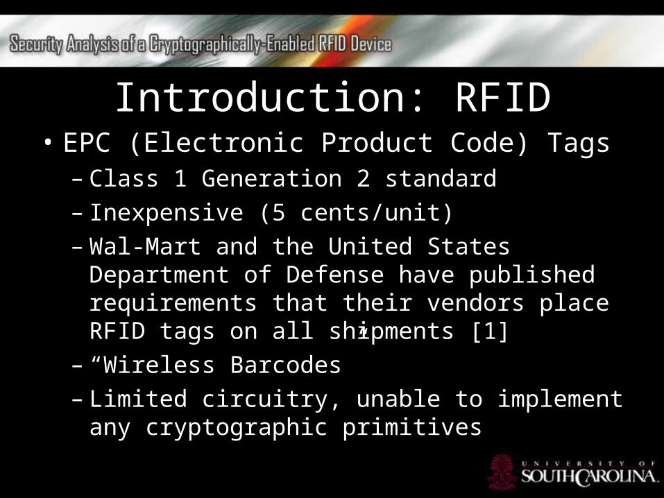
Introduction: RFID• EPC (Electronic Product Code) Tags– Class 1 Generation 2 standard– Inexpensive (5 cents/unit)– Wal-Mart and the United States Department of
Defense have published requirements that their vendors place RFID tags on all shipments [1]
– “Wireless Barcodes”– Limited circuitry, unable to implement any
cryptographic primitives

Introduction: RFID• EPC (Electronic Product Code) Tags
ALN-9540 - "Squiggle™" • World Tag: global operation 860 to 960 MHz • The EPC Class 1 Gen 2 price/performance benchmark • High performance solution for most packaging including
products containing metal and water • 97mm x 11mm ALN-9529 - "Squiggle®-SQ"• Global operation - 860 to 960 MHz • Ideal for item level tagging of plastic packaging such as
pharmaceutical pill bottles and apparel hang tags • Near-field and far-field communication modes • 23mmx 23m

Introduction: RFID• Digital Signal Transponder– Manufactured by Texas Instruments– Vehicle immobilizer keys• RFID ID embedded in Key• Condition for enabling
Fuel-Injection system
– Electronic Payment• Exxon-Mobil SpeedPass™

Introduction: RFID• Digital Signal Transponder– Consists of microchip and antenna cased in plastic
or glass– Passive RFID device• Allows for small design and long life
– Contains secret 40-bit Key– Reader initiates connection, DST emits 24-bit
identifier (factory-set)– DST authenticates itself via a Challenge-Response
protocol

Introduction: RFID• Digital Signal Transponder: Challenge-
Response protocol
– Reader initiates protocol with 40-bit challenge
– DST encrypts challenge using its key and truncates resulting cyphertext to return a 24-bit response
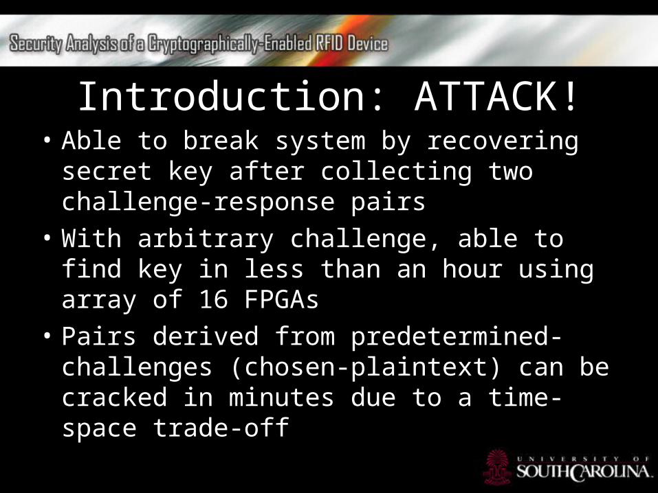
Introduction: ATTACK!• Able to break system by recovering secret key
after collecting two challenge-response pairs• With arbitrary challenge, able to find key in
less than an hour using array of 16 FPGAs• Pairs derived from predetermined-challenges
(chosen-plaintext) can be cracked in minutes due to a time-space trade-off

Introduction: ATTACK!• Team showed that with cheap commodity
hardware, an attacker could break the DTS system– Recover key by actively scanning at short range
for fraction of a second (skimming)– With FPGA, attacker can simulate target after
capturing multiple transcripts

Introduction: ATTACK!To validate:• Team found key from their purchased
SpeedPass™ and simulated the DTS to successfully make a purchase at an Exxon-Mobil Station
• Team found cryptographic key from DST ignition key, and was able to start a vehicle

Introduction: ATTACK!Phase 1: Reverse Engineering• After obtaining rough schematic of the block
cipher for the challenge response, they were able to determine all details of the cipher
• Required experimental observation of inputs and outputs

Introduction: ATTACK!Phase 2: Key Cracking• Assembled array of 16 FPGA’s working in
parallel• Able to crack arbitrary challenge in less than
an hour• Also assembled FPGA for time-space trade-off
[12]

Introduction: ATTACK!Phase 3: Simulation• Given the key and serial number for a DST
device, they were able to simulate its output• Simulation in software radio• Required careful analysis of the DST reader
output

Related Work• Classic Black-box example:
Duplicating the Purple encipher machine to reconstruct the Japanese Foreign Officer cipher during second World War
• Reverse-engineering of RC4 cipher as well as A5/1 and A5/2 ciphers in GSM phones
• No published black-box reverse-engineering of recent ciphers; developed custom techniques

Related Work• Key Recovery more well known• FPGA scheme similar to Deep Crack for
recovering DES keys• Chosen-challenge pairs uses time-space
tradeoff as Hellman describes in his work• Authors also use “distinguished point”
enhancement of Rivest

Significance and Implications• Purpose is not to undermine the SpeedPass™
network, nor to allow easier theft of vehicles• Exxon-Mobil has several layers of security,
including fraud detection• Largest threat to SpeedPass™ is attacker
simulating multiply DSTs (suspicious use disables it)

Significance and Implications• Serious threat to Vehicles • Renders vehicle as vulnerable as one without
the immobilizer• Significant decline in auto-thefts is attributed
to the immobilizers

Significance and ImplicationsEffective Attack Range• Two different methods for capturing signals from
DST: Active Scanning and Passive Eavesdropping– Active Scanning: attacker brings their own reader
within range of DST (up to several inches) for only a few seconds• This type of attack could allow for an attacker to
harvest two chosen-challenge transcripts and perform look-ups on Hellman tables on the cracking device

Significance and ImplicationsEffective Attack Range• Two different methods for capturing signals from
DST: Active Scanning and Passive Eavesdropping– Passive Eavesdropping : an attacker listens to
legitimate communication between DST and reader during authentic session• Range depends on the ability to intercept signal from
DST• Range not found in this study

Significance and ImplicationsExample Attack Scenarios• Example 1: Auto theft via eavesdropping– Eve owns can with necessary equipment– Parks close enough to target to eavesdrop– Observe two successful session, Eve can extract
key at her convenience using FPGA– Eve returns to steal vehicle by picking door lock,
disabling immobilizer with found, and hot-wiring ignition

Significance and ImplicationsExample Attack Scenarios• Example 2: Auto theft via active attack– Eve gets access to valet key storage to scan
immobilizer keys of patrons– Record registration numbers (to get owner info)– Eve then can simulate devices and steal the
vehicles from owner’s home

Significance and ImplicationsExample Attack Scenarios• Example 3: SpeedPassTM theft via active
attack– Eve brings reader and short-range antenna on
subway– Harvests challenge-response pairs and serials
from SpeedPass™ devices– Eve can recover crypto keys at her convenience– Uses key in software radio to purchase gasoline

Significance and ImplicationsFixes• Underlying protocols should be based on publicly
scrutinized standards with sufficient key length, such as the Advanced Encryption Algorithm
• Problems: – Cost to make capable devices would significantly
increase– Backwards compatibility (significant cost to
refit/recall existing devices)

Significance and ImplicationsFixes• Faraday shielding provides a partial solution– Users can encase DSTs in adequate shielding like
aluminum foil to reflect radio while not in use– Protects against active scanning, but not
eavesdropping– Possible shielding around reader to defend against
eavesdropping

Reverse Engineering

Reverse Engineering• Authors found schematic by Dr. Kaiser and TI
in a presentation• Functional components were clear, but critical
details of logic and interconnects were not• Certain features in schematic were wrong• Chose “black-box” approach by examining
logical outputs• Authors Purchased TI Series 2000 – LF RFID
Evaluation Kit and DST devices

Reverse Engineering• DST 40 is essentially a feedback shift register• During each round, inputs from challenge
register and key register pass through collection of logical units
• These units produce an output that is put back into the challenge register

Reverse Engineering• Single round as all units is referred to as F. F
has three logical layers: – First layer: represented as f1 to f16 (f-boxes)– The second layer is represented as f17 to f20,
referred to as g-boxes, which are four functional units that takes the outputs of set of four f-boxes as inputs
– The third layer is a single unit, f21, in which takes in the outputs of the g-boxes, called the h-box, returns the output of the full function F
Reverse Engineering• There are two main technical details missing
from the schematic:– Does not describe the logical operations of the f,
g, and h-boxes– Does not describe the routing array for the
mapping of key and challenge bits to the f-boxes

Reverse EngineeringObtaining a Single-Round Output• Since the contents of the f-boxes and critical
routing was unknown, the authors could not directly verify if their DSTs followed the Kaiser schematic
• Required to treat evaluation DST as a “Black-box”• From the schematic, the authors noted that the
only round dependence is in the key scheduler• used the string of ‘0’ bits for their starting
experiments

Reverse EngineeringObtaining a Single-Round Output• After each cycle, there were only small changes
to contents of the challenge register:– Each was shifted right one bit– The output of the h-box was inserted into the left-
most bit position– Challenge/Response
• two possible sequences, either:C0 = 0|C or C1 = 1|C, where | denotes concatenation
• after the first cycle, h-box output assumes challenge register is either C0 or C1 after first cycle
Reverse EngineeringObtaining a Single-Round Output• Tests failed, indicating that the DST40 differs
from the Kaiser cipher• Authors found that testing next-state
challenge response values succeeded when they modeled the h-box output as two bits
• Authors then questioned elements of the schematic including number of rounds and key update schedule

Reverse EngineeringObtaining a Single-Round Output• Since the authors were able to recover the
output of F on a single iteration, they were able to observe the entirety of each round of a cipher execution by repeatedly guessing the next state of challenge register
• They established that the encryption took over 200 cycles and the DST gets its response from the right-most 24 bits of the challenge register

Reverse EngineeringRecovering the Key Schedule• Using the ‘0’ bit key would restrict ability to
experiment with algorithm internals• They required the ability to observe single-round
outputs based on different values in the challenge and key registers
• Using a non-zero key makes the algorithm round dependent
• Needed to provide black-box with equivalent next key register state

Reverse EngineeringRecovering the Key Schedule• By following the diagram, the authors assumed new
key bits were computed by exclusive-or of several bits of the key every few seconds
• They determined the key is updated every three cycles (beginning with the second cycle)– Let ki denote the ith bit in the key register beginning with 0– The key update is defined by:
k0 = k39 k37 k20 k18
• Using this model in place of the ‘0’ bit key, they were able to simulate steps for any key

Reverse EngineeringRecovering the Key Schedule• Previously only had to guess each possibility for a
2-bit output of single round• For a non-zero key, need to guess six successive
bits (three bit-pairs) of output for the h-box at the same time, since the key schedule only repeats every 3 cycles
• This meant testing 64 possible candidate challenge-response states
• To test, they set the k’ corresponding to the key-register state after 6 cycles applied to k

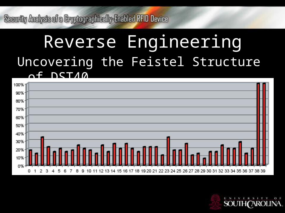
Reverse EngineeringUncovering the Feistel Structure of DST40• To measure the effect, the authors generated
a random key and challenge, and determined the output of F
• For each of the 40 challenge bits, they determined whether F changed upon flipping a bit
• Repeated 150 times
Reverse EngineeringUncovering the Feistel Structure of DST40

Reverse EngineeringUncovering the Feistel Structure of DST40• The XOR of bits c38 and c39 showed that the
algorithm was an invertible permutation and it is a form of Unbalanced Feistel Network
• The authors speculate that the round function was chosen so that collisions would not multiply and responses would have uniform distribution

Reverse EngineeringRecovering the Bit Routing Networks• Next step was to recover internal routing
network of bits• Assumption that the h-box (f21) was the only
box with a 2-bit output• Structure of Kaiser cipher shows that h gets a
single bit from each of the g-boxes and returns one or four possible outputs

Reverse EngineeringRecovering the Bit Routing Networks• Using this observation, the authors devised a test to
see which groups of input bits of the challenge and key are routed to each of four g-boxes
• Test requires many repetitions since two test bits could be routed to different g-boxes, and different value outputs still produce two or fewer distinct outputs
• The routing network was arranged in a regular pattern, and after uncovering most of the bits dealing with g1 and the authors were able to infer and validate the remainder of g-boxes

Reverse EngineeringRecovering the Bit Routing Networks• An f-box uses a fixed boolean function z on five bit
inputs• Suppose that B is the set of inputs to this f-box:– Then let’s define A0 to be the set of value assignments to
the bits in B such that z(b1 . . . b5) = 0– Also, define A1 analogously for z(b1 . . . b5) = 1 – Notice that for a fixed setting of B, the output of h will be
invariant for the setting of B to any value in A0. – Likewise, for a fixed value assignment to B, the output of h
will be invariant for any setting of B to a value in A1.

Reverse EngineeringRecovering the Bit Routing Networks• Using the invariant, the authors performed tests to
exclude combinations of bits that can’t be inputs the same f-box
• Next step was to Iterate over all 32 value assignments to B and record the output pattern from F
• They then repeated the experiment over B• If no invariant like described, the B cannot consist of
inputs to a single f-box• Test repeated until excluded all possible inputs except
for correct ones

Reverse EngineeringBuilding Logical Tables for the f, g, and h-boxes• Once the corresponding bits to each f-box were
identified, the authors constructed tables to represent logical functions computed by all the boxes
• To calculate the f-box tables, they simply iterated through 32 possible input value for the set B that corresponds to the f-box
• To calculate a given g-box, four corresponding f-boxes and iterated over all 24 = 16 combinations of their output values
• It’s essentially the same method to construct the h-box table; though the h-box outputs two bits instead of one

Key CrackingThe DST40 Keycracker• First implemented in software• To slow for a keycracker• Software could only compute less than 200,000
encryptions per second on 3.4 GHz Pentium• Time would take more than 2 weeks for a 10
node cluster• Decided to implement the keycracker in
hardware

Key CrackingThe DST40 Keycracker• Each node consisted of a single Xilinx XC3S1000
FPGA• 32 cores per FPGA• Since DST40 outputs 24 bits per 40 bit challenge,
at least two challenge/response pairs are needed to determine a unique key
• Clock on board was fixed to 100 MHz, allowing for 16 million keys per second
• Entire 40 bit key-space can be exhausted in less than 21 hours

Key CrackingThe DST40 Keycracker• Single FPGA board was enough to verify
testing• Cracker recoverd key from SpeedPass™ in
under 11 hours• Bought a total 16 evaluation boards to get a
significantly reduced crack time• Cracked 5 TI DST tags and recovered all keys in
less than 2 hours

Key CrackingThe Hellman Time-Space Tradeoff• As described, Software key cracker uses
Hellman tables• Estimates suggest a 99+% success rate• Requires 10 GB of storage• Should finish in under one minute on fast PC• Table construction requires a large amount of
pre-computation

RF Protocol Analysis and Simulation• A reader in the DST system transmits power to
the transponder at a 15-to-50 ms electromagnetic pulse at 134.2 kHz
• Once powered, transponder can perform session tasks
• Reader transmits as a sequence of amplitude-modulated bits
• Once transponder has received and processed a command, it discharges its power while transmitting response

RF Protocol Analysis and SimulationSniffing the Protocol• The team configured a portable PC with a digital-to-
analog board• Designed to send and receive desired analog signals• The authors wrote routines for modulation and
demodulation to produce the signals produced by the reader and FM-FSK signals produced from the transponder
• Using this equipment can allow for successful eavesdropping or actively participate by emulating either reader or transponder

RF Protocol Analysis and SimulationPutting Together the Pieces: the Full DST Protocol• First, the reader transmits a challenge request
to the transponder– Consists of an 8-bit opcode followed by the 40-bit
challenge (opcode specifies type of request being made)
– The transponder encrypts the challenge using the shared secret 40-bit key
– The least significant 24 bits in the transponder challenge register consitutes a 24-bit Signature

RF Protocol Analysis and SimulationPutting Together the Pieces: the Full DST Protocol• The transponder then responds– Replies with 24-bit serial number, 24-bit signature,
and a keyed 16-bit CRC of the transmitted data
• Using the shared encryption key and secret CRC start value, the reader can then verify
• The CRC is intended to add extra security as well as provide error checking

RF Protocol Analysis and SimulationPutting Together the Pieces: the Full DST Protocol• The stated aim of DST was to make it resistant
to:– Signature-guessing attacks– Dictionary attacks– Attacks using known challenge-response pairs– Cryptanalytic attacks– Exhaustive key search

RF Protocol Analysis and SimulationSimulating a DST Device• The authors software performs the following:– It analyzes the A/D conversions received from the
DAC board– Decodes the AM signal containing the challenge sent
from the reader – Performs an encryption of this challenge using the
recovered secret DST key– Codes the FM-FSK signal representing the correct
response– Outputs this FM-FSK signal to the DAC board

Conclusion• The weakness of DST40 cipher demonstrated
by the authors is primarily due to an insufficient key-length
• Further cryptanalysis may reveal weaknesses in the cipher
• Systems with the strongest security are generally standard cryptographic algorithms with adequate key lengths

Questions?

References[1]. http://en.wikipedia.org/wiki/RFID[2]. http
://en.wikipedia.org/wiki/Digital_Signature_Transponder
Recommended