Design of a 100 MT per day
Sulfuric Acid (98.5 wt%) Plant
by
Hla Tun (0502004)
Mir Rezwan Rahman (0502030)
Muhammad Rejwan Billah (0502040)
Joyanta Goswami (0502050)
Supervised by
Dr. Syeda Sultana Razia
Associate Professor
Department of Chemical Engineering
Bangladesh University of Engineering & Technology (BUET)
Dhaka, Bangladesh
i
Acknowledgement
As the authors of this design project we are especially grateful to Dr. Syeda Sultana
Razia, Associate Professor, Department of Chemical Engineering, BUET, for her
prospective guidance and support throughout the course of the design project. We are
also grateful to B.M. Sirajeel Arifin and K.M. Tanvir Ahmmed, Lectureres, Department of
Chemical Engineering, for accompanying us during the industrial visit of sulfuric acid
plant and for their assistance regarding our project design. Moreover, we would like to
thank the engineers of Crescent chemicals for assisting us with industrial data of
sulfuric acid plant.
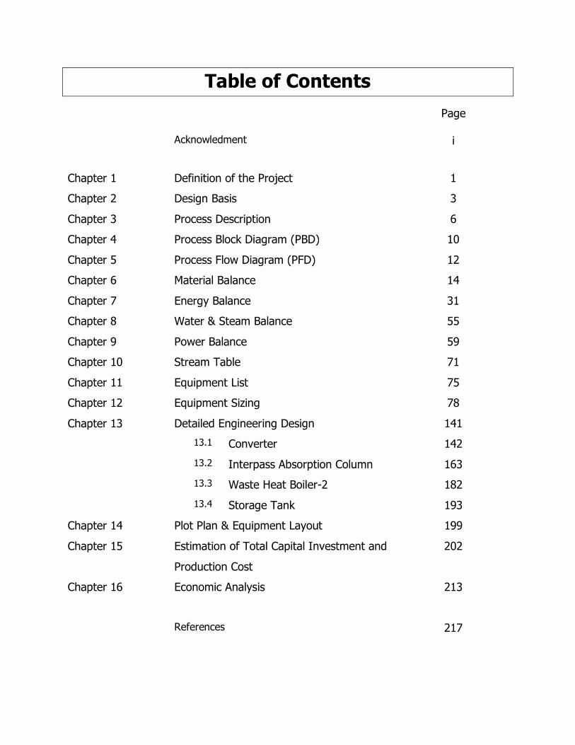
Table of Contents
Page
Acknowledment
i
Chapter 1 Definition of the Project 1
Chapter 2 Design Basis 3
Chapter 3 Process Description 6
Chapter 4 Process Block Diagram (PBD) 10
Chapter 5 Process Flow Diagram (PFD) 12
Chapter 6 Material Balance 14
Chapter 7 Energy Balance 31
Chapter 8 Water & Steam Balance 55
Chapter 9 Power Balance 59
Chapter 10 Stream Table 71
Chapter 11 Equipment List 75
Chapter 12 Equipment Sizing 78
Chapter 13 Detailed Engineering Design 141
13.1 Converter 142
13.2 Interpass Absorption Column 163
13.3 Waste Heat Boiler-2 182
13.4 Storage Tank 193
Chapter 14 Plot Plan & Equipment Layout 199
Chapter 15 Estimation of Total Capital Investment and
Production Cost
202
Chapter 16 Economic Analysis 213
References 217

Chapter One
Definition of the Project
2
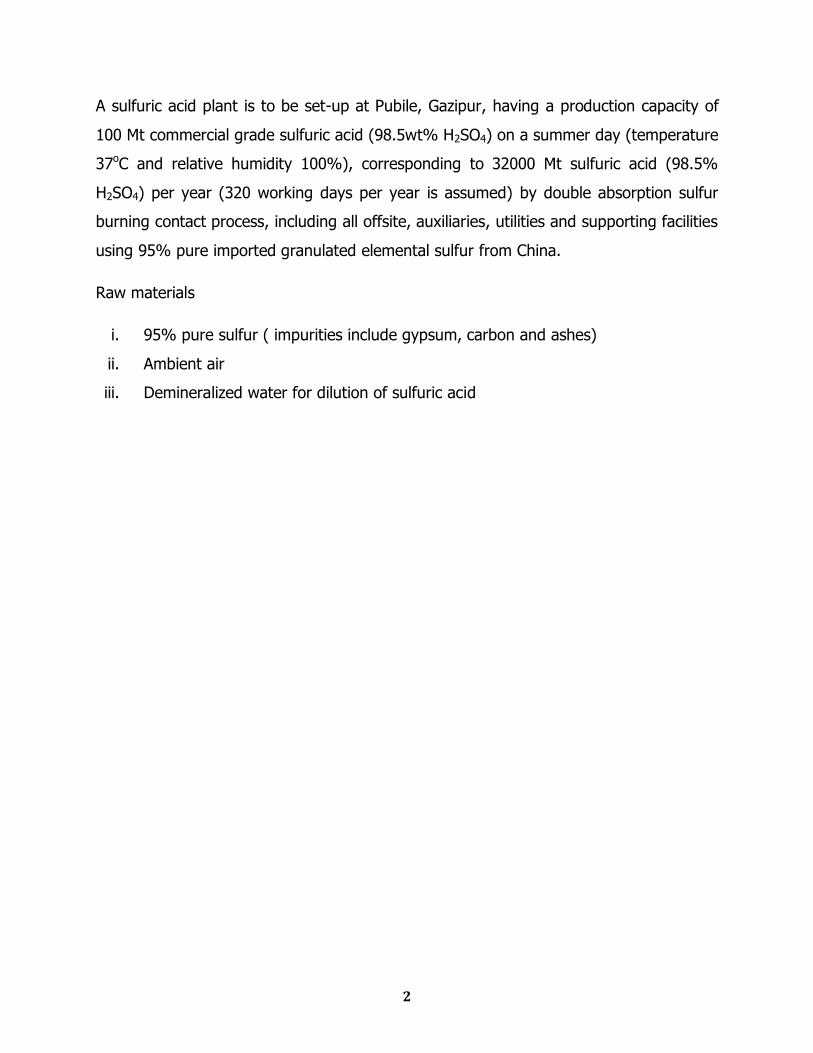
A sulfuric acid plant is to be set-up at Pubile, Gazipur, having a production capacity of
100 Mt commercial grade sulfuric acid (98.5wt% H2SO4) on a summer day (temperature
37oC and relative humidity 100%), corresponding to 32000 Mt sulfuric acid (98.5%
H2SO4) per year (320 working days per year is assumed) by double absorption sulfur
burning contact process, including all offsite, auxiliaries, utilities and supporting facilities
using 95% pure imported granulated elemental sulfur from China.
Raw materials
i. 95% pure sulfur ( impurities include gypsum, carbon and ashes)
ii. Ambient air
iii. Demineralized water for dilution of sulfuric acid

Chapter Two
Design Basis
4
1. Meteorological data for the site
i) Temperatures
Maximum temperature - 34oC (April)
Average annual temperature -27oC
Lowest temperature -14oC (December)
ii) Rainfall
Annual rainfall – 1875 mm
Average monthly rainfall – 156 mm
Maximum rainfall – 337 mm (August wettest month)
Minimum rainfall – 5 mm ( December driest month)
iii) Humidity
Average annual relative humidity – 65.8%
Average monthly humidity (maximum) – 79% (June)
Average monthly humidity (minimum) – 45% (March)
iv) Wind
Average wind speed – 9.7 km/h
Design wind speed – 125 km/h
Design wind loading – 80 kg/m2
v) Design conditions
Dry bulb temperature – 37 oC
Wet bulb temperature - 37 oC
Relative humidity – 100%
2. Utility
i) Steam:
Low pressure steam – 150o C at 4.5 kgf /cm2
ii) Water – Ground water at 20oC treated to soft water for cooling
5
iii) Major electric power requirements:
Blower – 222.8 kW
Pump1 – 0.0074 kW
Pump2 – 0.0147 kW
Pump3 – 0.43 kW
Pump4 – 0.075 kW
Pump5 – 0.122 kW
Melter – 51.8 kW
3. Raw material:
95% pure granulated sulfur
4. Process air – 2 atm (absolute)

Chapter Three
Process Description
7
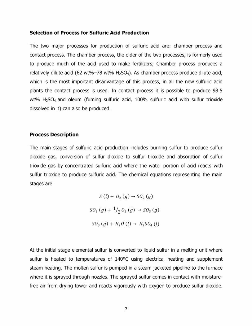
Selection of Process for Sulfuric Acid Production
The two major processes for production of sulfuric acid are: chamber process and
contact process. The chamber process, the older of the two processes, is formerly used
to produce much of the acid used to make fertilizers; Chamber process produces a
relatively dilute acid (62 wt%–78 wt% H2SO4). As chamber process produce dilute acid,
which is the most important disadvantage of this process, in all the new sulfuric acid
plants the contact process is used. In contact process it is possible to produce 98.5
wt% H2SO4 and oleum (fuming sulfuric acid, 100% sulfuric acid with sulfur trioxide
dissolved in it) can also be produced.
Process Description
The main stages of sulfuric acid production includes burning sulfur to produce sulfur
dioxide gas, conversion of sulfur dioxide to sulfur trioxide and absorption of sulfur
trioxide gas by concentrated sulfuric acid where the water portion of acid reacts with
sulfur trioxide to produce sulfuric acid. The chemical equations representing the main
stages are:
At the initial stage elemental sulfur is converted to liquid sulfur in a melting unit where
sulfur is heated to temperatures of 140ºC using electrical heating and supplement
steam heating. The molten sulfur is pumped in a steam jacketed pipeline to the furnace
where it is sprayed through nozzles. The sprayed sulfur comes in contact with moisture-
free air from drying tower and reacts vigorously with oxygen to produce sulfur dioxide.
8
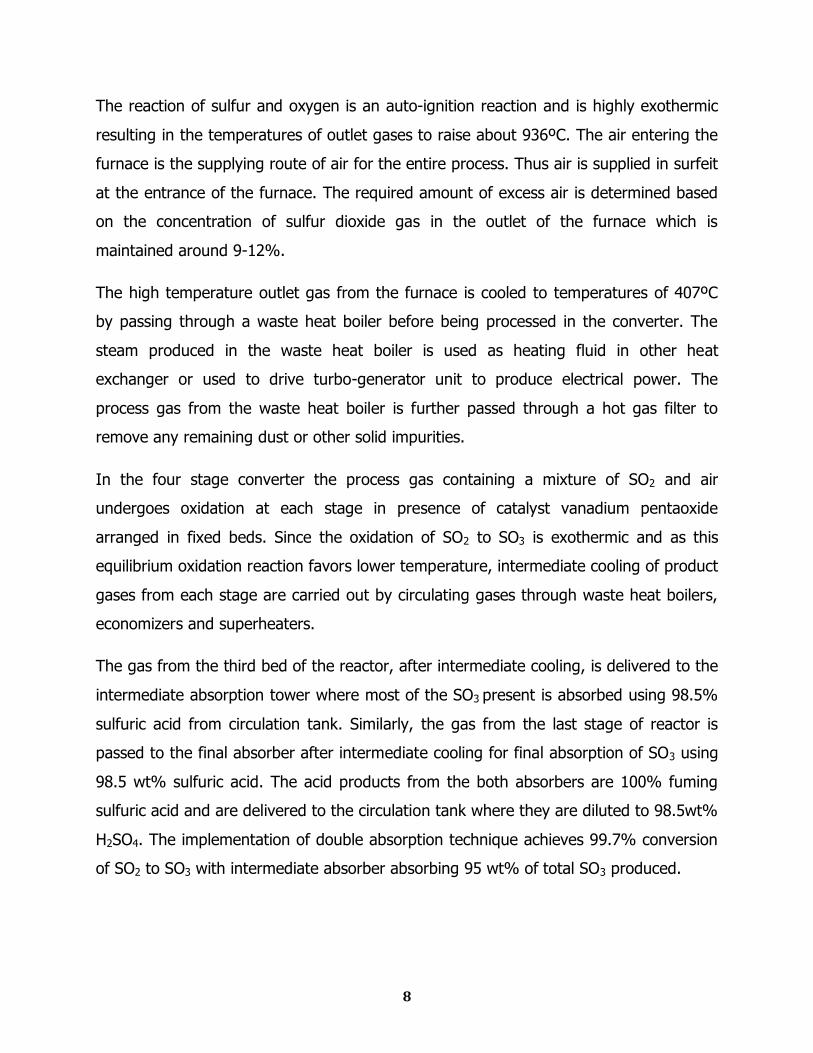
The reaction of sulfur and oxygen is an auto-ignition reaction and is highly exothermic
resulting in the temperatures of outlet gases to raise about 936ºC. The air entering the
furnace is the supplying route of air for the entire process. Thus air is supplied in surfeit
at the entrance of the furnace. The required amount of excess air is determined based
on the concentration of sulfur dioxide gas in the outlet of the furnace which is
maintained around 9-12%.
The high temperature outlet gas from the furnace is cooled to temperatures of 407ºC
by passing through a waste heat boiler before being processed in the converter. The
steam produced in the waste heat boiler is used as heating fluid in other heat
exchanger or used to drive turbo-generator unit to produce electrical power. The
process gas from the waste heat boiler is further passed through a hot gas filter to
remove any remaining dust or other solid impurities.
In the four stage converter the process gas containing a mixture of SO2 and air
undergoes oxidation at each stage in presence of catalyst vanadium pentaoxide
arranged in fixed beds. Since the oxidation of SO2 to SO3 is exothermic and as this
equilibrium oxidation reaction favors lower temperature, intermediate cooling of product
gases from each stage are carried out by circulating gases through waste heat boilers,
economizers and superheaters.
The gas from the third bed of the reactor, after intermediate cooling, is delivered to the
intermediate absorption tower where most of the SO3 present is absorbed using 98.5%
sulfuric acid from circulation tank. Similarly, the gas from the last stage of reactor is
passed to the final absorber after intermediate cooling for final absorption of SO3 using
98.5 wt% sulfuric acid. The acid products from the both absorbers are 100% fuming
sulfuric acid and are delivered to the circulation tank where they are diluted to 98.5wt%
H2SO4. The implementation of double absorption technique achieves 99.7% conversion
of SO2 to SO3 with intermediate absorber absorbing 95 wt% of total SO3 produced.
9
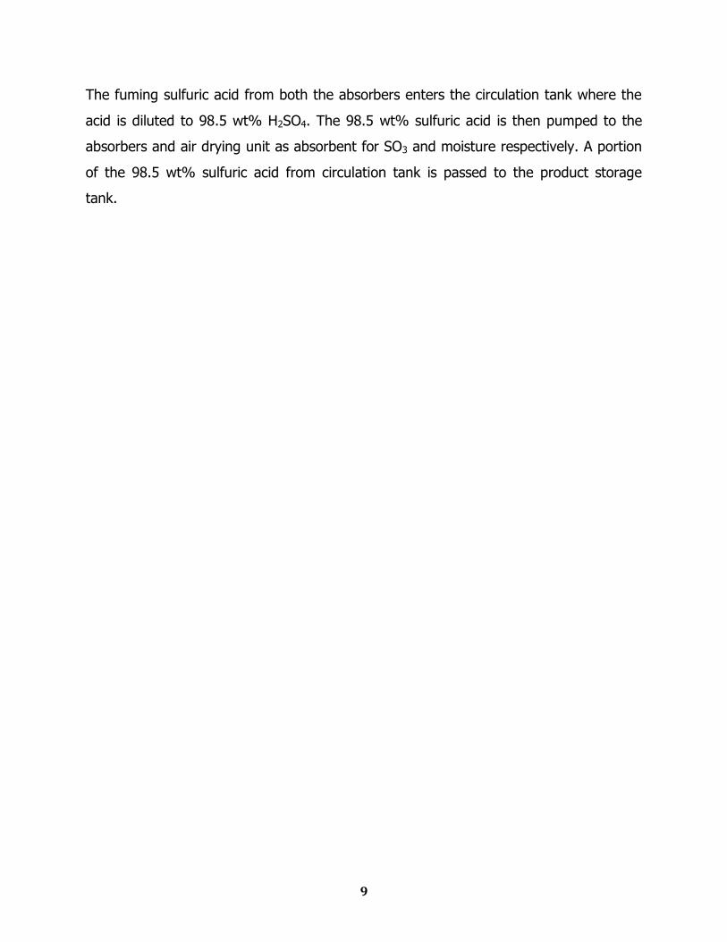
The fuming sulfuric acid from both the absorbers enters the circulation tank where the
acid is diluted to 98.5 wt% H2SO4. The 98.5 wt% sulfuric acid is then pumped to the
absorbers and air drying unit as absorbent for SO3 and moisture respectively. A portion
of the 98.5 wt% sulfuric acid from circulation tank is passed to the product storage
tank.

Chapter Four
Process Block Diagram
11
Drying
Tower
Furnace
Melter
HE-1HE-2
Interpass
absorption
Tower
Final
Absorptio
n Tower
Circulation
Tank
Elemental
Sulfur
Converter
Air
Product Acid
98.5 wt %
Dilution
Water
To Stack
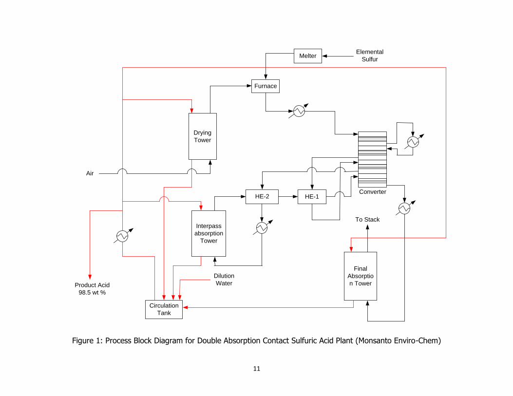
Figure 1: Process Block Diagram for Double Absorption Contact Sulfuric Acid Plant (Monsanto Enviro-Chem)

Chapter Five
Process Flow Diagram
1
4
5
6
9
12
13
14
15
16
18 19
20
21
22
23
24
3
2
29
30
31
32
34
39
Air
Solid
Sulfur
To
Stack
Dilution
Water
Dilution
Water
Q-120
R-130
Q-121
D-110
D-140
D-150
E-131
E-132
E-133E-142
E-143
E-151
E-152
E-141
E-162
F-154
F-144
F-160
L-122
E-153
L-145
E-111
G-112
7
8
10
2625
27
11
33
17
28
35
37
38
L-146
L-161
36
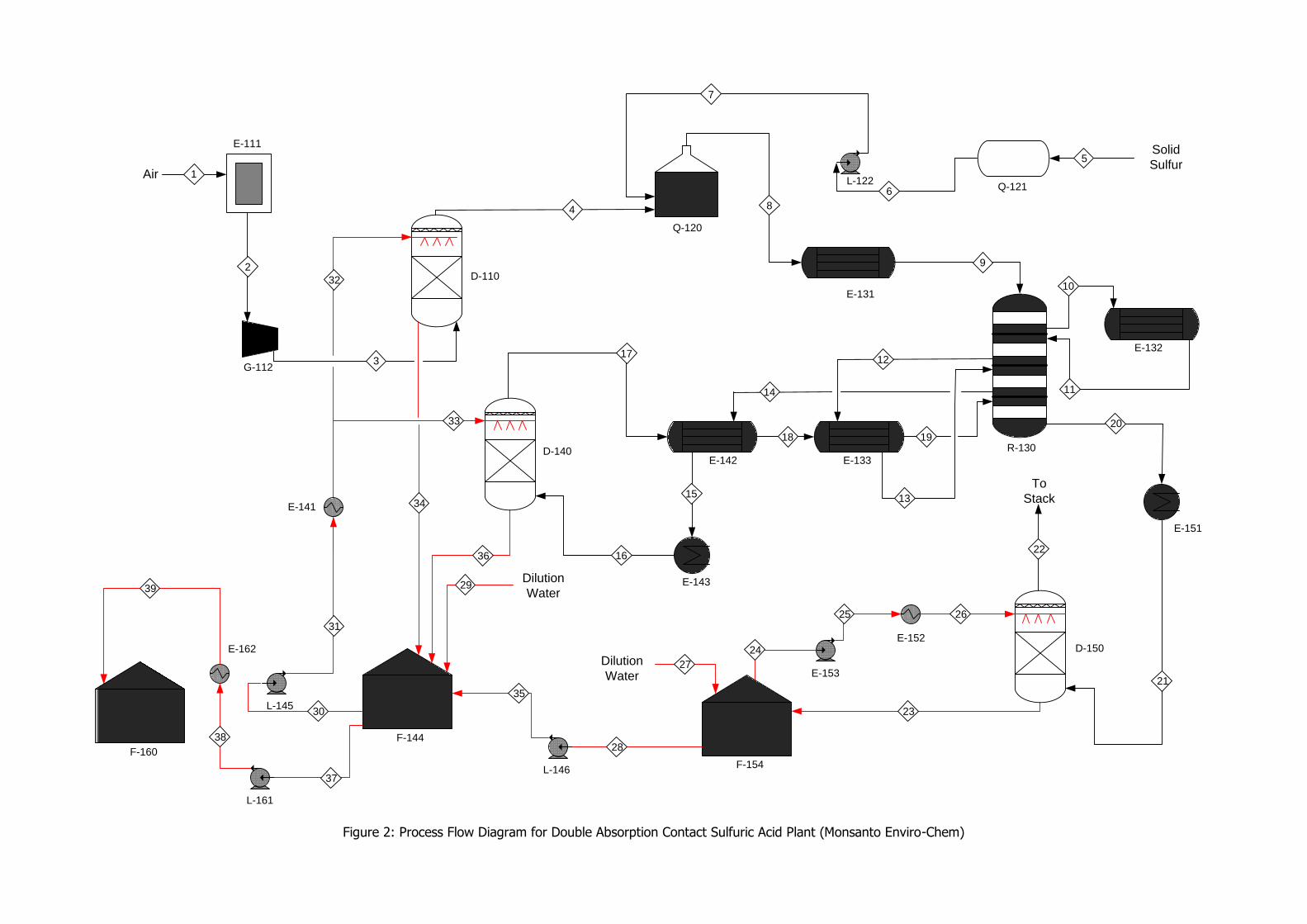
Figure 2: Process Flow Diagram for Double Absorption Contact Sulfuric Acid Plant (Monsanto Enviro-Chem)

Chapter Six
Material Balance
15
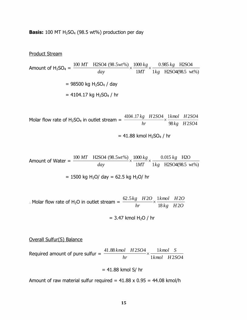
Basis: 100 MT H2SO4 (98.5 wt%) production per day
Product Stream
Amount of H2SO4 = wt%)H2SO4(98.51
H2SO4985.0
1
1000%)5.98(H2SO4100
kg
kg
MT
kg
day
wtMT
= 98500 kg H2SO4 / day
= 4104.17 kg H2SO4 / hr
Molar flow rate of H2SO4 in outlet stream = 4298
4214217.4104
SOHkg
SOHkmol
hr
SOHkg
= 41.88 kmol H2SO4 / hr
Amount of Water = wt%)H2SO4(98.51
H2O015.0
1
1000%)5.98(H2SO4100
kg
kg
MT
kg
day
wtMT
= 1500 kg H2O/ day = 62.5 kg H2O/ hr
Molar flow rate of H2O in outlet stream = OHkg
OHkmol
hr
OHkg
218
2125.62
= 3.47 kmol H2O / hr
Overall Sulfur(S) Balance
Required amount of pure sulfur = 421
14288.41
SOHkmol
Skmol
hr
SOHkmol
= 41.88 kmol S/ hr
Amount of raw material sulfur required = 41.88 x 0.95 = 44.08 kmol/h
16
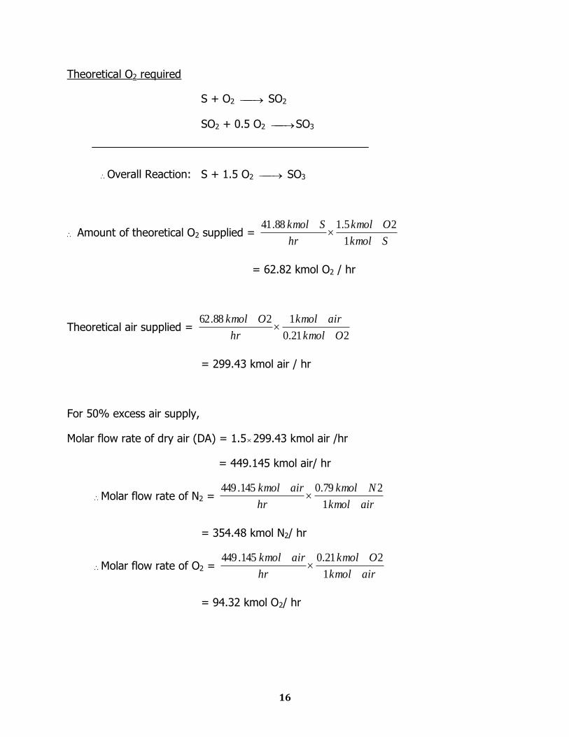
Theoretical O2 required
S + O2 SO2
SO2 + 0.5 O2 SO3
Overall Reaction: S + 1.5 O2 SO3
Amount of theoretical O2 supplied = Skmol
Okmol
hr
Skmol
1
25.188.41
= 62.82 kmol O2 / hr
Theoretical air supplied = 221.0
1288.62
Okmol
airkmol
hr
Okmol
= 299.43 kmol air / hr
For 50% excess air supply,
Molar flow rate of dry air (DA) = 1.5299.43 kmol air /hr
= 449.145 kmol air/ hr
Molar flow rate of N2 = airkmol
Nkmol
hr
airkmol
1
279.0145.449
= 354.48 kmol N2/ hr
Molar flow rate of O2 = airkmol
Okmol
hr
airkmol
1
221.0145.449
= 94.32 kmol O2/ hr
17
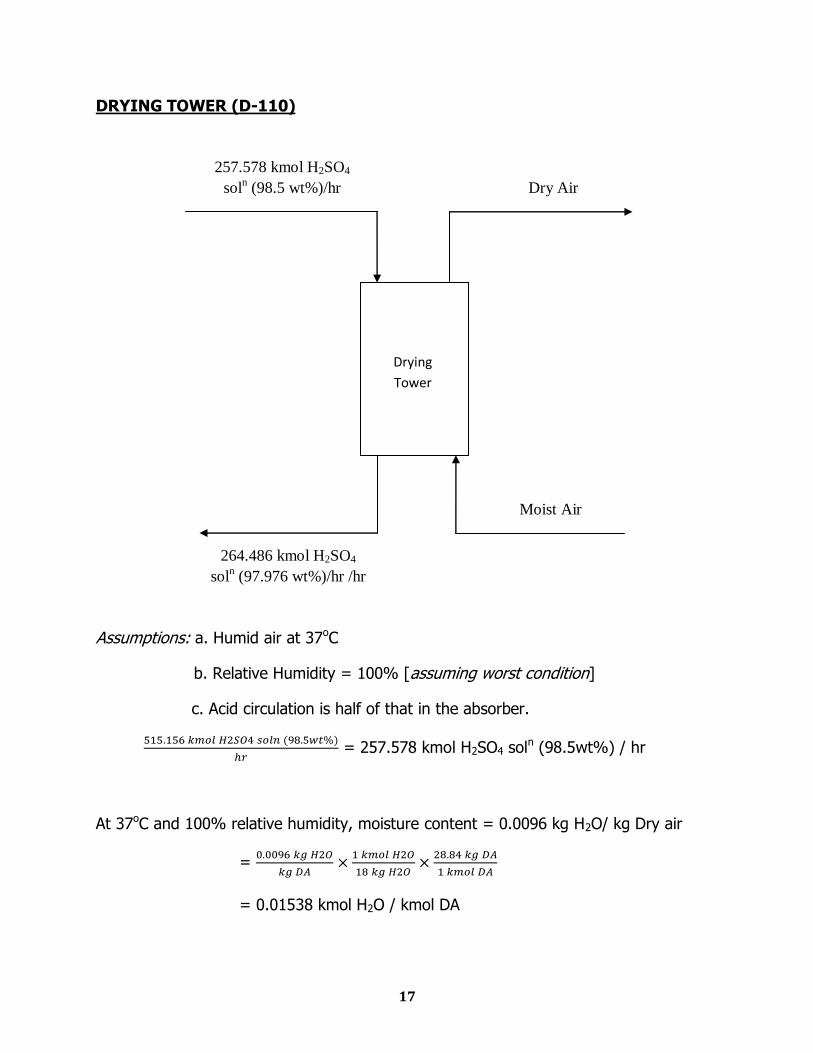
DRYING TOWER (D-110)
Assumptions: a. Humid air at 37oC
b. Relative Humidity = 100% [assuming worst condition]
c. Acid circulation is half of that in the absorber.
= 257.578 kmol H2SO4 soln (98.5wt%) / hr
At 37oC and 100% relative humidity, moisture content = 0.0096 kg H2O/ kg Dry air
=
= 0.01538 kmol H2O / kmol DA
264.486 kmol H2SO4
soln (97.976 wt%)/hr /hr
257.578 kmol H2SO4
soln (98.5 wt%)/hr Dry Air
Moist Air
Drying
Tower
18
Amount of inlet moisture (H2O) =
= 6.908 kmol H2O/ hr
Compositions of 98.5wt% H2SO4 soln is 0.923 kmol H2SO4/kmol and 0.077 kmol
H2O/kmol
H2SO4 Balance: 257.578 0.923 = Px
Px = 237.744……………………(1)
H2O Balance: 257.578 0.077 + 6.908= P(1-x)
P(1-x) = 26.742
P – Px = 26.742
P – 237.744 = 42.502 [from equation (1)]
P = 264.486 kmol/hr
from equation (1)
x =
= 0.8989 mol%
Molar flow rate of outlet H2SO4 soln = (257.578 + 6.908) kmol H2SO4 soln
= 264.486 H2SO4 soln
1 kmol H2SO4 = 98 kg H2SO4
0.8989 kmol H2SO4 = 98 0.8989 = 88.0922 kg H2SO4
(1-0.8989) kmol H2O = 1.8198 kg H2O
wt% of H2SO4 solution =
= 97.976 wt%
19
FURNACE (Q-121)
S + O2 SO2
Amount of O2 that reacts = 41.88 kmol O2/hr
Molar flow rate of SO2 = 41.88 kmol SO2/hr
Molar flow rate of O2 at furnace outlet = (94.23 – 41.88) kmol O2/hr
= 52.35 kmol O2/hr
Molar flow rate of N2 at outlet stream = 354.48 kmol N2/hr
Outlet composition:
0.093 kmol SO2 / kmol
0.117 kmol O2 / kmol
0.790 kmol N2 / kmol
20
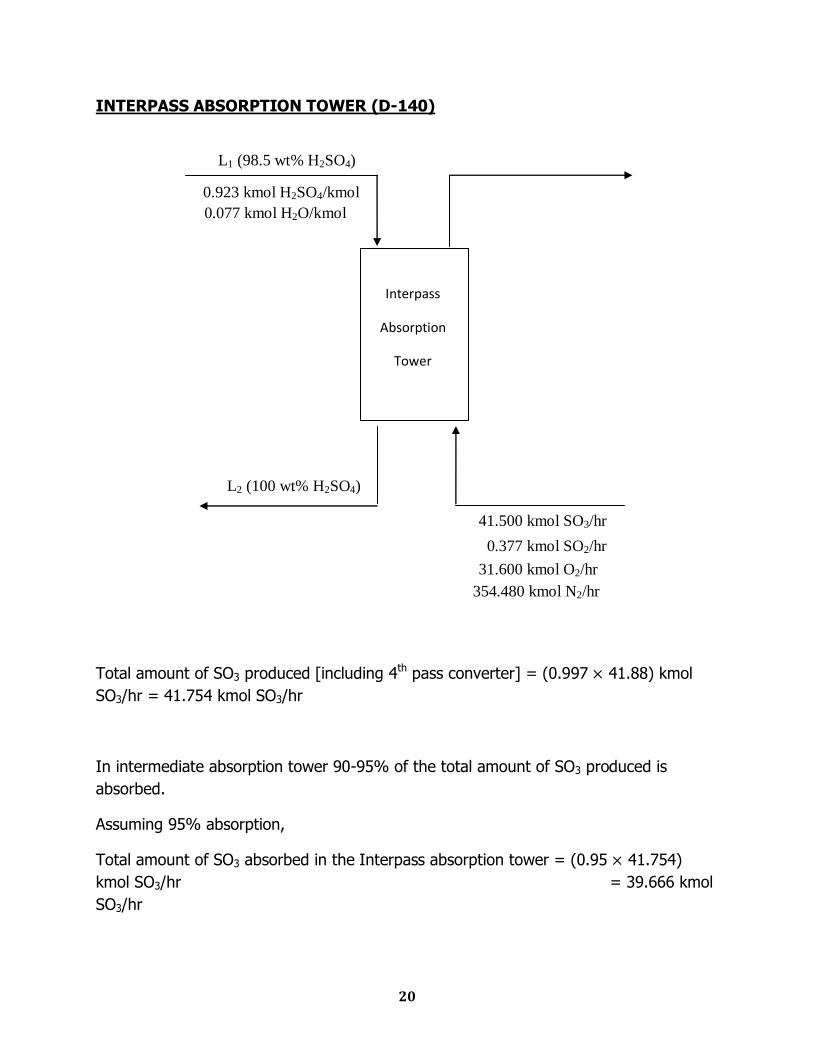
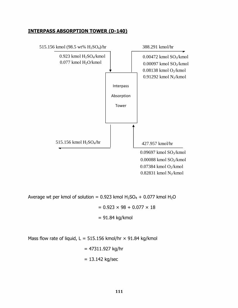
INTERPASS ABSORPTION TOWER (D-140)
Total amount of SO3 produced [including 4th pass converter] = (0.997 41.88) kmol
SO3/hr = 41.754 kmol SO3/hr
In intermediate absorption tower 90-95% of the total amount of SO3 produced is
absorbed.
Assuming 95% absorption,
Total amount of SO3 absorbed in the Interpass absorption tower = (0.95 41.754)
kmol SO3/hr = 39.666 kmol
SO3/hr
Interpass
Absorption
Tower
0.923 kmol H2SO4/kmol
0.077 kmol H2O/kmol
41.500 kmol SO3/hr
0.377 kmol SO2/hr
31.600 kmol O2/hr
354.480 kmol N2/hr
L1 (98.5 wt% H2SO4)
L2 (100 wt% H2SO4)
21
Amount of SO3 in the gas outlet from the absorber = 41.50 – 39.666 = 1.834 kmol
SO3/hr
In 1 kg 98.5 wt% H2SO4, amount of H2SO4 = 0.985 kg
Amount of H2SO4 in mole = 0.985/98 = 0.01 kmol H2SO4
Amount of H2O in mole = 0.015/18 = 0.00083 kmol H2O
Composition of H2SO4 in 98.5 wt% H2SO4 =
= 0.923 mol H2SO4/ kmol soln
Composition of H2O = 0.077 kmo H2O/kmol soln
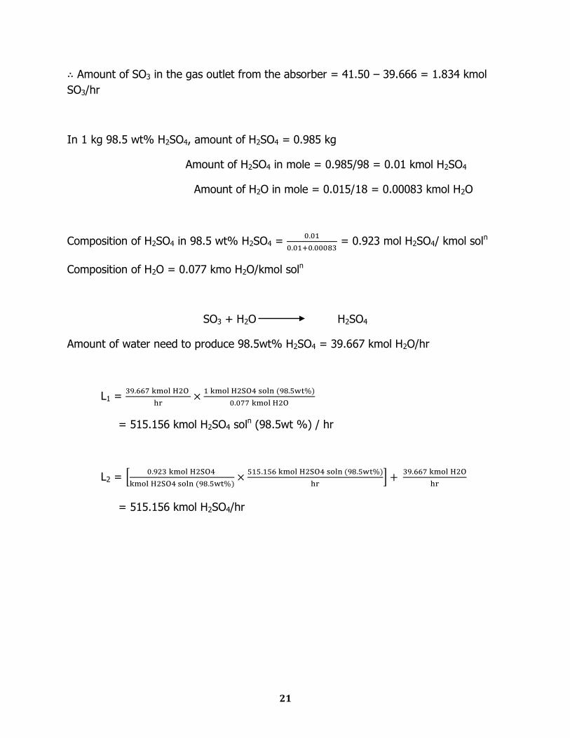
SO3 + H2O H2SO4
Amount of water need to produce 98.5wt% H2SO4 = 39.667 kmol H2O/hr
L1 =
= 515.156 kmol H2SO4 soln (98.5wt %) / hr
L2 =
= 515.156 kmol H2SO4/hr
22
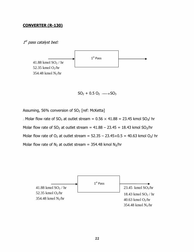
CONVERTER (R-130)
1st pass catalyst bed:
SO2 + 0.5 O2 SO3
Assuming, 56% conversion of SO2 [ref: McKetta]
Molar flow rate of SO3 at outlet stream = 0.56 41.88 = 23.45 kmol SO3/ hr
Molar flow rate of SO2 at outlet stream = 41.88 – 23.45 = 18.43 kmol SO2/hr
Molar flow rate of O2 at outlet stream = 52.35 – 23.45 0.5 = 40.63 kmol O2/ hr
Molar flow rate of N2 at outlet stream = 354.48 kmol N2/hr
1st Pass
41.88 kmol SO2 / hr
52.35 kmol O2/hr
354.48 kmol N2/hr
1st Pass 41.88 kmol SO2 / hr
52.35 kmol O2/hr
354.48 kmol N2/hr 18.43 kmol SO2 / hr
40.63 kmol O2/hr
23.45 kmol SO3/hr
354.48 kmol N2/hr
23
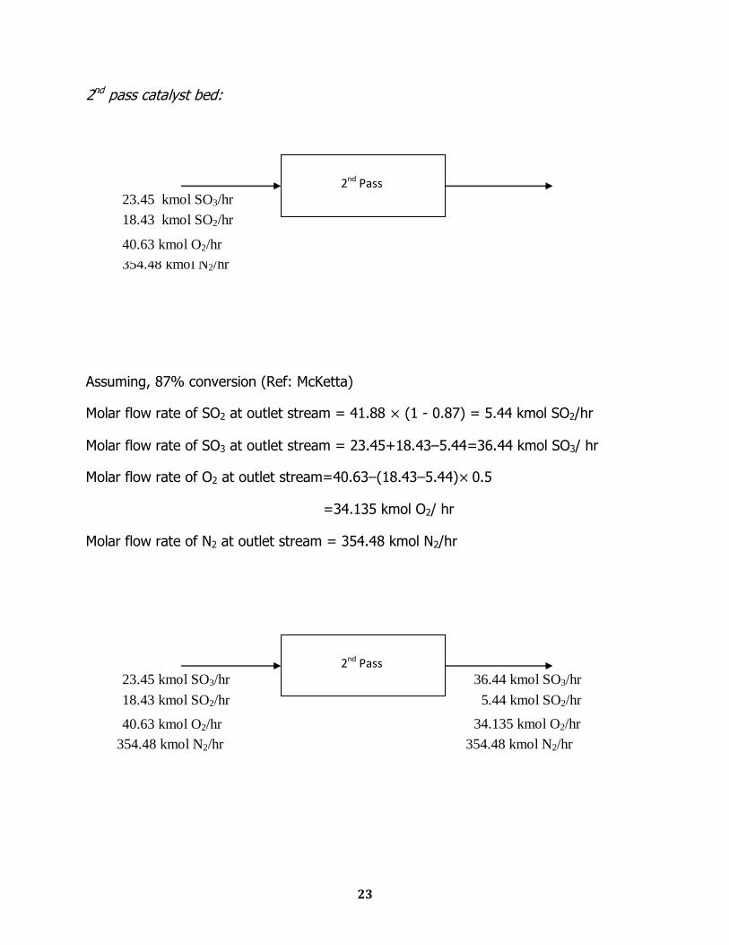
2nd pass catalyst bed:
Assuming, 87% conversion (Ref: McKetta)
Molar flow rate of SO2 at outlet stream = 41.88 (1 - 0.87) = 5.44 kmol SO2/hr
Molar flow rate of SO3 at outlet stream = 23.45+18.43–5.44=36.44 kmol SO3/ hr
Molar flow rate of O2 at outlet stream=40.63–(18.43–5.44) 0.5
=34.135 kmol O2/ hr
Molar flow rate of N2 at outlet stream = 354.48 kmol N2/hr
2nd Pass
40.63 kmol O2/hr
23.45 kmol SO3/hr
354.48 kmol N2/hr
18.43 kmol SO2/hr
2nd Pass
23.45 kmol SO3/hr
354.48 kmol N2/hr
18.43 kmol SO2/hr
40.63 kmol O2/hr
36.44 kmol SO3/hr
5.44 kmol SO2/hr
34.135 kmol O2/hr
354.48 kmol N2/hr
24
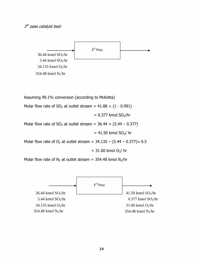
3rd pass catalyst bed:
Assuming 99.1% conversion (according to McKetta)
Molar flow rate of SO2 at outlet stream = 41.88 (1 - 0.991)
= 0.377 kmol SO2/hr
Molar flow rate of SO3 at outlet stream = 36.44 + (5.44 – 0.377)
= 41.50 kmol SO3/ hr
Molar flow rate of O2 at outlet stream = 34.135 – (5.44 – 0.377) 0.5
= 31.60 kmol O2/ hr
Molar flow rate of N2 at outlet stream = 354.48 kmol N2/hr
3rd Pass
36.44 kmol SO3/hr
5.44 kmol SO2/hr
34.135 kmol O2/hr
354.48 kmol N2/hr
3rd Pass
36.44 kmol SO3/hr
34.135 kmol O2/hr
354.48 kmol N2/hr
5.44 kmol SO2/hr
41.50 kmol SO3/hr
0.377 kmol SO2/hr
31.60 kmol O2/hr
354.48 kmol N2/hr
25
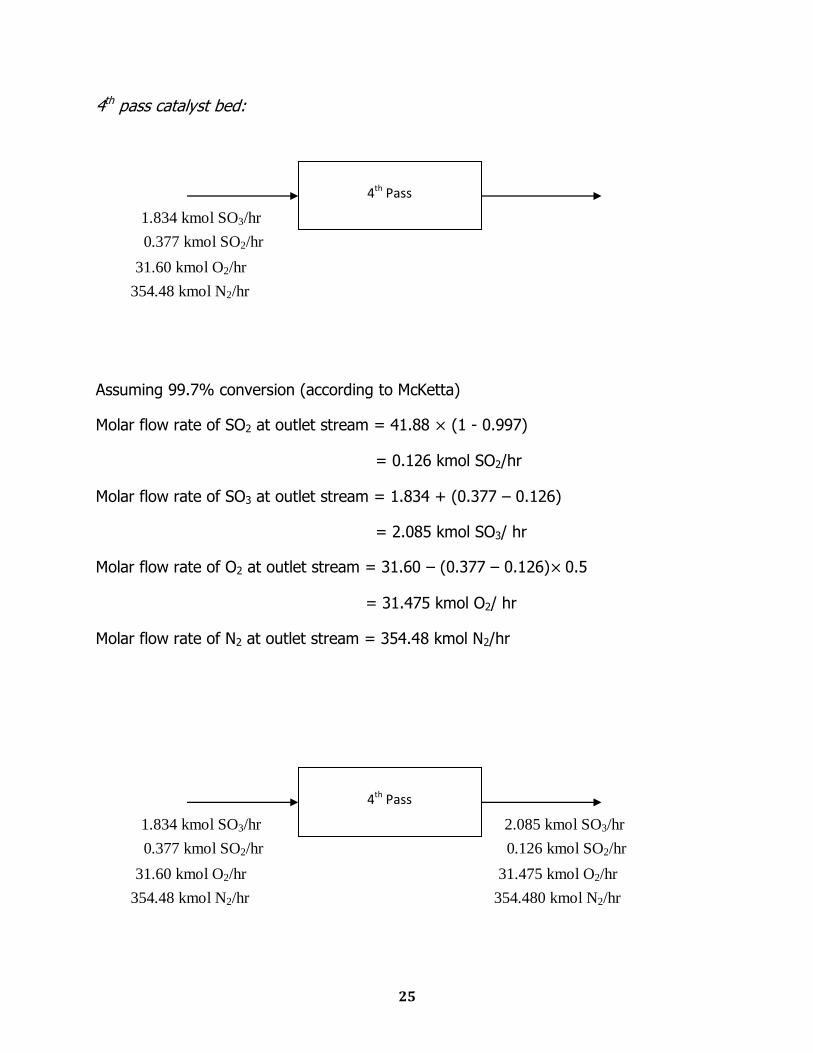
4th pass catalyst bed:
Assuming 99.7% conversion (according to McKetta)
Molar flow rate of SO2 at outlet stream = 41.88 (1 - 0.997)
= 0.126 kmol SO2/hr
Molar flow rate of SO3 at outlet stream = 1.834 + (0.377 – 0.126)
= 2.085 kmol SO3/ hr
Molar flow rate of O2 at outlet stream = 31.60 – (0.377 – 0.126) 0.5
= 31.475 kmol O2/ hr
Molar flow rate of N2 at outlet stream = 354.48 kmol N2/hr
4th Pass
1.834 kmol SO3/hr
0.377 kmol SO2/hr
31.60 kmol O2/hr
354.48 kmol N2/hr
4th Pass
1.834 kmol SO3/hr
0.377 kmol SO2/hr
31.60 kmol O2/hr
354.48 kmol N2/hr
2.085 kmol SO3/hr
0.126 kmol SO2/hr
31.475 kmol O2/hr
354.480 kmol N2/hr
26
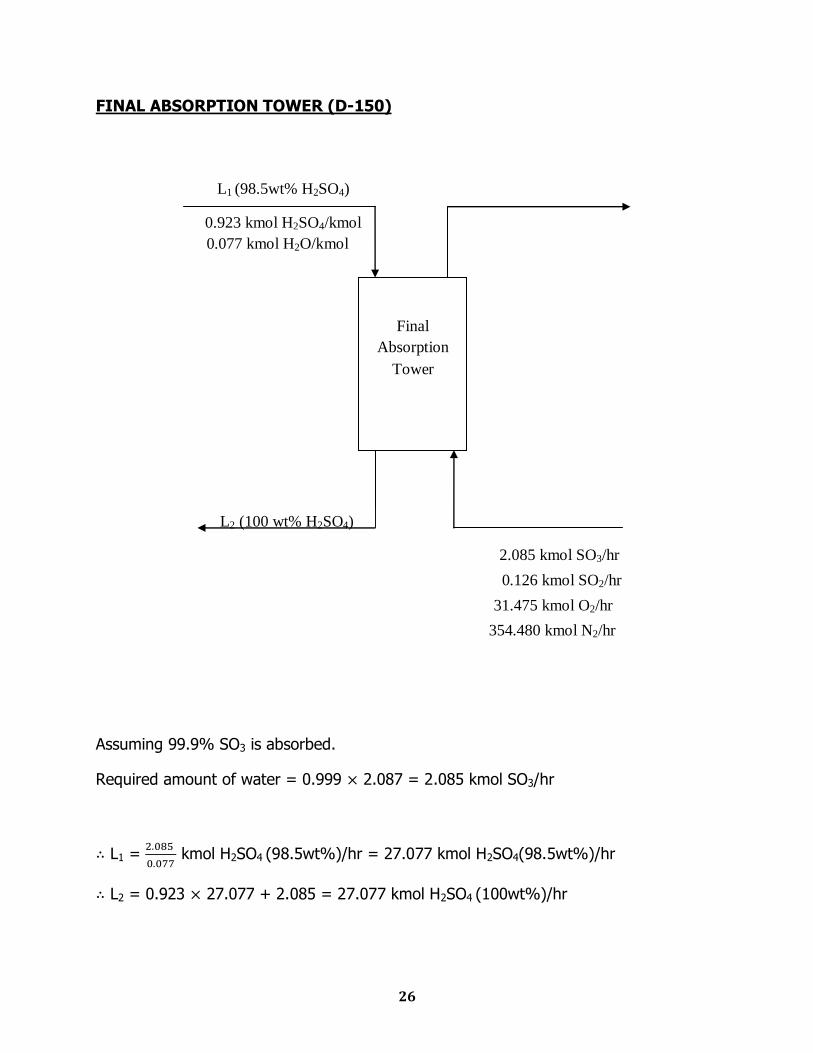
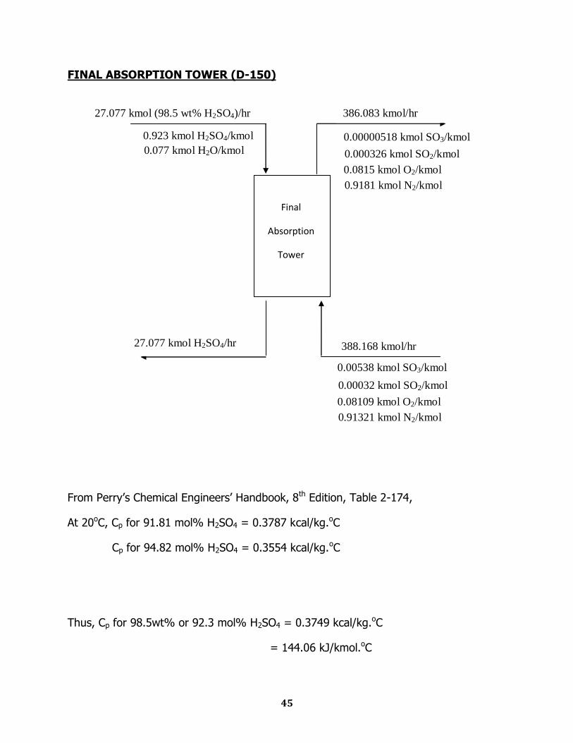
FINAL ABSORPTION TOWER (D-150)
Assuming 99.9% SO3 is absorbed.
Required amount of water = 0.999 2.087 = 2.085 kmol SO3/hr
L1 =
kmol H2SO4 (98.5wt%)/hr = 27.077 kmol H2SO4(98.5wt%)/hr
L2 = 0.923 27.077 + 2.085 = 27.077 kmol H2SO4 (100wt%)/hr
Final
Absorption
Tower
0.923 kmol H2SO4/kmol
0.077 kmol H2O/kmol
L1 (98.5wt% H2SO4)
L2 (100 wt% H2SO4)
2.085 kmol SO3/hr
0.126 kmol SO2/hr
31.475 kmol O2/hr
354.480 kmol N2/hr
27
Thus, Outlet gas stream is as follow:
Amount of SO3 at outlet stream = 2.087 – 2.085 = 0.002 kmol SO3/hr
Amount of SO2 at outlet stream = 0.126 kmol SO2/hr
Amount of O2 at outlet stream = 31.475 kmol O2/hr
Amount of N2 at outlet stream = 354.48 kmol N2/hr
28
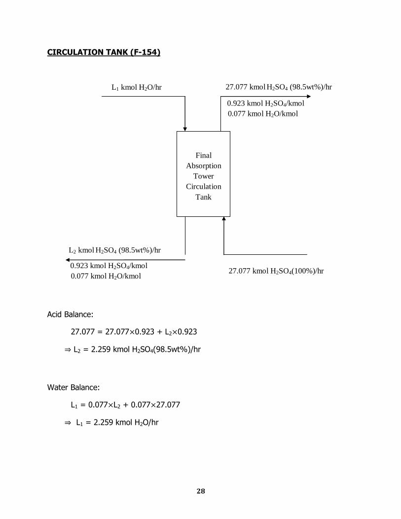
CIRCULATION TANK (F-154)
Acid Balance:
27.077 = 27.077 0.923 + L2 0.923
L2 = 2.259 kmol H2SO4(98.5wt%)/hr
Water Balance:
L1 = 0.077 L2 + 0.077 27.077
L1 = 2.259 kmol H2O/hr
0.923 kmol H2SO4/kmol
0.077 kmol H2O/kmol
L2 kmol H2SO4 (98.5wt%)/hr
L1 kmol H2O/hr
0.923 kmol H2SO4/kmol
0.077 kmol H2O/kmol
27.077 kmol H2SO4 (98.5wt%)/hr
Final
Absorption
Tower
Circulation
Tank
27.077 kmol H2SO4(100%)/hr
29
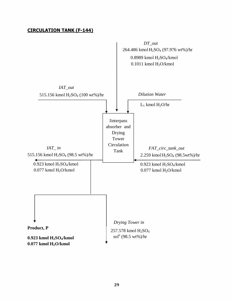
CIRCULATION TANK (F-144)
L1 kmol H2O/hr
0.8989 kmol H2SO4/kmol
0.1011 kmol H2O/kmol
DT_out
Drying Tower in
IAT_ in
515.156 kmol H2SO4 (98.5 wt%)/hr
0.923 kmol H2SO4/kmol
0.077 kmol H2O/kmol
IAT_out
515.156 kmol H2SO4 (100 wt%)/hr
FAT_circ_tank_out
0.923 kmol H2SO4/kmol
0.077 kmol H2O/kmol
2.259 kmol H2SO4 (98.5wt%)/hr
Dilution Water
Iinterpass
absorber and
Drying
Tower
Circulation
Tank
Product, P
0.923 kmol H2SO4/kmol
0.077 kmol H2O/kmol
257.578 kmol H2SO4
soln (98.5 wt%)/hr
264.486 kmol H2SO4 (97.976 wt%)/hr
30
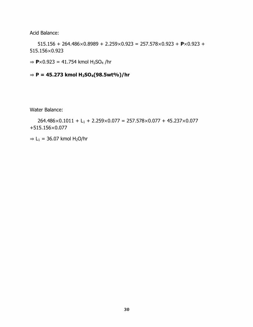
Acid Balance:
515.156 + 264.486 0.8989 + 2.259 0.923 = 257.578 0.923 + P 0.923 +
515.156 0.923
P 0.923 = 41.754 kmol H2SO4 /hr
P = 45.273 kmol H2SO4(98.5wt%)/hr
Water Balance:
264.486 0.1011 + L1 + 2.259 0.077 = 257.578 0.077 + 45.237 0.077
+515.156 0.077
L1 = 36.07 kmol H2O/hr

Chapter Seven
Energy Balance
32
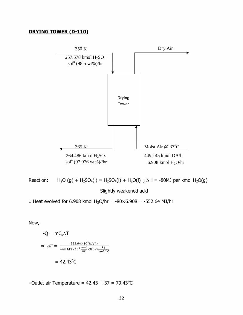
DRYING TOWER (D-110)
Reaction: H2O (g) + H2SO4(l) = H2SO4(l) + H2O(l) ; H = -80MJ per kmol H2O(g)
Slightly weakened acid
Heat evolved for 6.908 kmol H2O/hr = -80 6.908 = -552.64 MJ/hr
Now,
-Q = mCpT
= 42.43oC
Outlet air Temperature = 42.43 + 37 = 79.43oC
449.145 kmol DA/hr
365 K
Dry Air 350 K
Moist Air @ 37oC
264.486 kmol H2SO4
soln (97.976 wt%)//hr
257.578 kmol H2SO4
soln (98.5 wt%)/hr
Drying
Tower
6.908 kmol H2O/hr
33
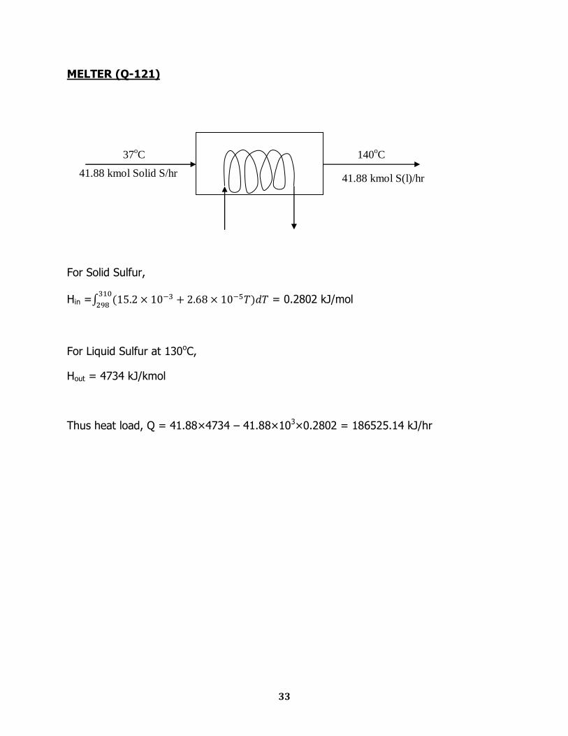
MELTER (Q-121)
For Solid Sulfur,
Hin =
= 0.2802 kJ/mol
For Liquid Sulfur at 130oC,
Hout = 4734 kJ/kmol
Thus heat load, Q = 41.88×4734 – 41.88×103×0.2802 = 186525.14 kJ/hr
140oC 37
oC
41.88 kmol Solid S/hr 41.88 kmol S(l)/hr
34
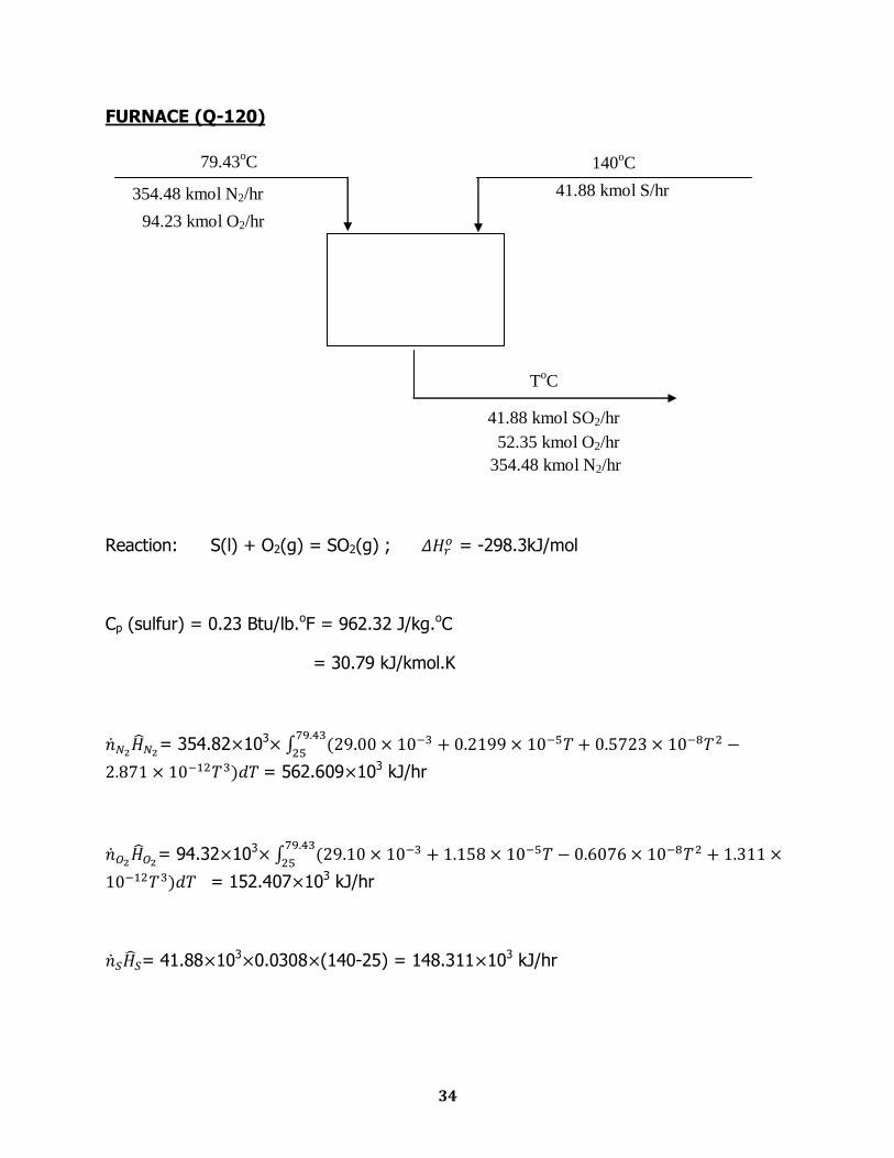
FURNACE (Q-120)
Reaction: S(l) + O2(g) = SO2(g) ; = -298.3kJ/mol
Cp (sulfur) = 0.23 Btu/lb.oF = 962.32 J/kg.oC
= 30.79 kJ/kmol.K
= 354.82 103
= 562.609 103 kJ/hr
= 94.32 103
= 152.407 103 kJ/hr
= 41.88 103 0.0308 (140-25) = 148.311 103 kJ/hr
ToC
41.88 kmol SO2/hr
140oC
41.88 kmol S/hr
79.43oC
354.48 kmol N2/hr
94.23 kmol O2/hr
52.35 kmol O2/hr
354.48 kmol N2/hr
35
Now, for adiabatic system,
Δ = - =0
-41.88 103 298.3 + - (562.609 103 + 152.407 103 +
148.311 103) = 0
= 13.693 106
41.88 103
+ 52.35 103
+ 354.82 103
= 13.693 106
T = 936.439oC
36
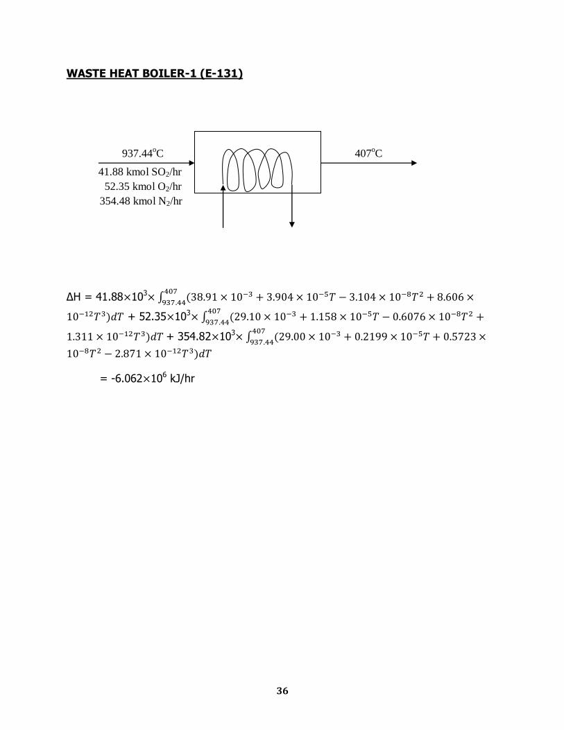
WASTE HEAT BOILER-1 (E-131)
ΔH = 41.88 103
+ 52.35 103
+ 354.82 103
= -6.062 106 kJ/hr
407oC 937.44
oC
41.88 kmol SO2/hr
52.35 kmol O2/hr
354.48 kmol N2/hr
37
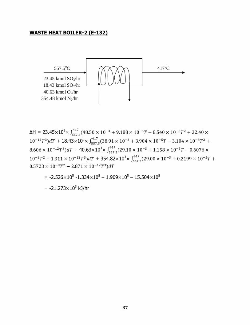
WASTE HEAT BOILER-2 (E-132)
ΔH = 23.45 103
+ 18.43 103
+ 40.63 103
+ 354.82 103
= -2.526 105 -1.334 105 – 1.909 105 – 15.504 105
= -21.273 105 kJ/hr
23.45 kmol SO3/hr
417oC 557.5
oC
18.43 kmol SO2/hr
40.63 kmol O2/hr
354.48 kmol N2/hr
38
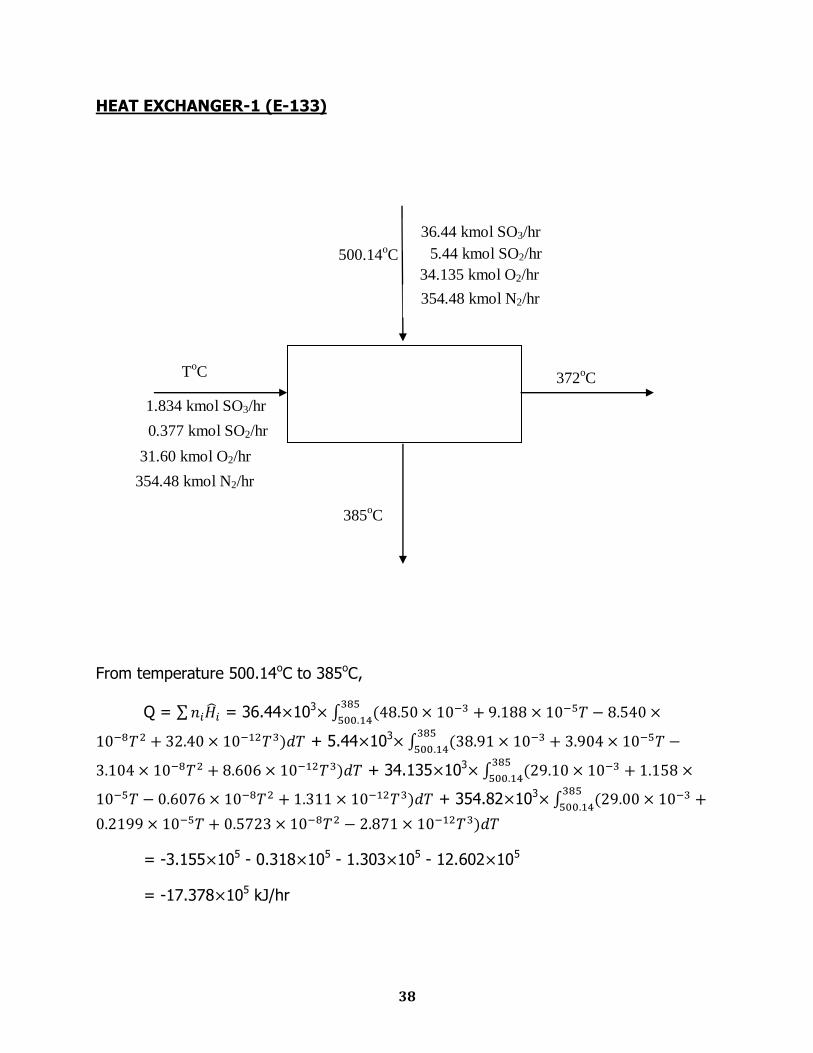
HEAT EXCHANGER-1 (E-133)
From temperature 500.14oC to 385oC,
Q = = 36.44 103
+ 5.44 103
+ 34.135 103
+ 354.82 103
= -3.155 105 - 0.318 105 - 1.303 105 - 12.602 105
= -17.378 105 kJ/hr
372oC
385oC
500.14oC
1.834 kmol SO3/hr
0.377 kmol SO2/hr
31.60 kmol O2/hr
354.48 kmol N2/hr
ToC
36.44 kmol SO3/hr
5.44 kmol SO2/hr
34.135 kmol O2/hr
354.48 kmol N2/hr
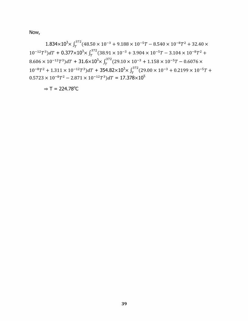
39
Now,
1.834 103
+ 0.377 103
+ 31.6 103
+ 354.82 103
= 17.378 105
T = 224.78oC
40
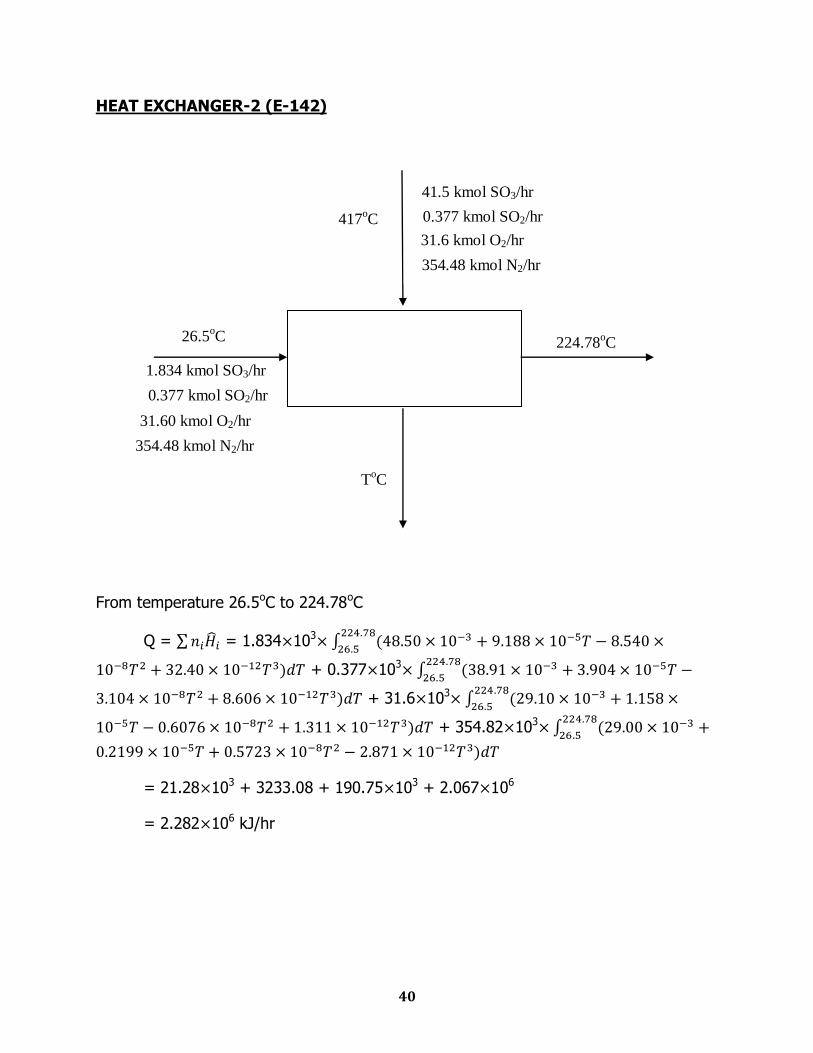
HEAT EXCHANGER-2 (E-142)
From temperature 26.5oC to 224.78oC
Q = = 1.834 103
+ 0.377 103
+ 31.6 103
+ 354.82 103
= 21.28 103 + 3233.08 + 190.75 103 + 2.067 106
= 2.282 106 kJ/hr
224.78oC
ToC
417oC
1.834 kmol SO3/hr
0.377 kmol SO2/hr
31.60 kmol O2/hr
354.48 kmol N2/hr
26.5oC
41.5 kmol SO3/hr
0.377 kmol SO2/hr
31.6 kmol O2/hr
354.48 kmol N2/hr
41
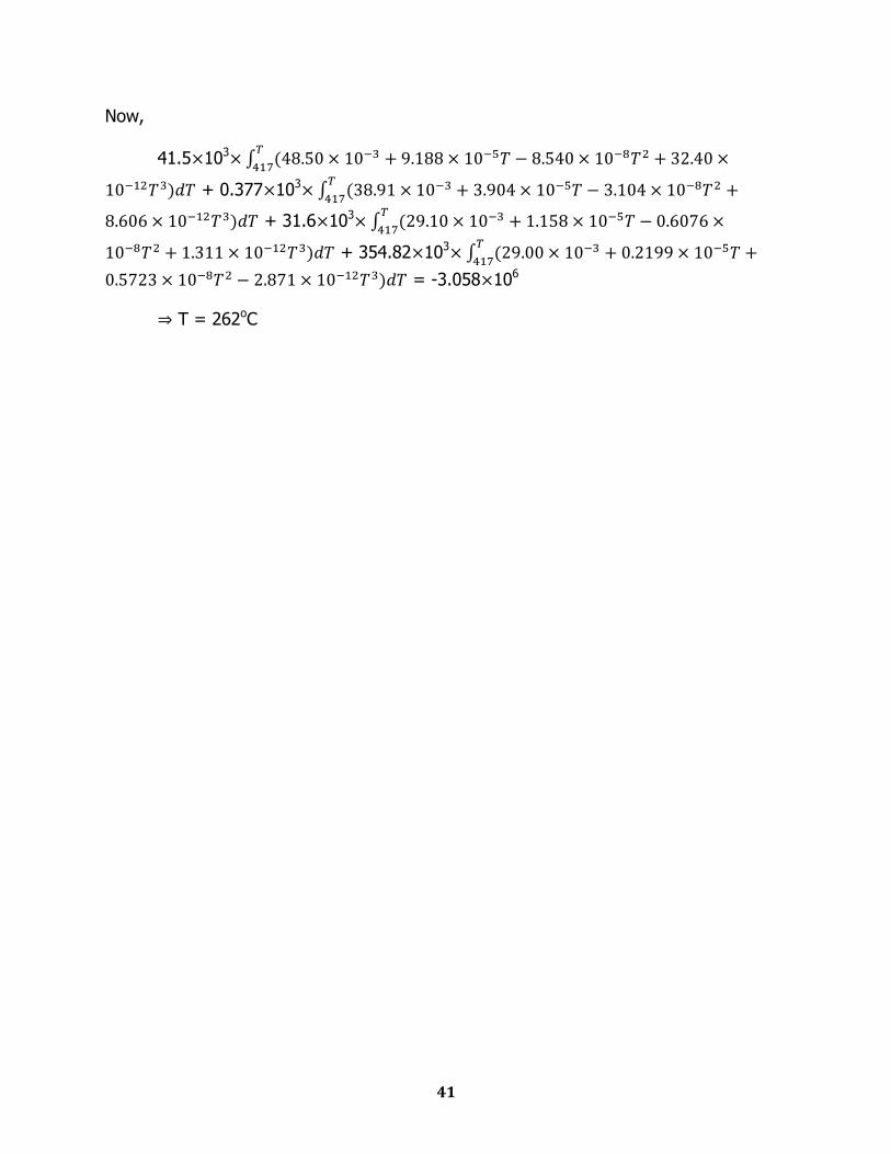
Now,
41.5 103
+ 0.377 103
+ 31.6 103
+ 354.82 103
= -3.058 106
T = 262oC
42
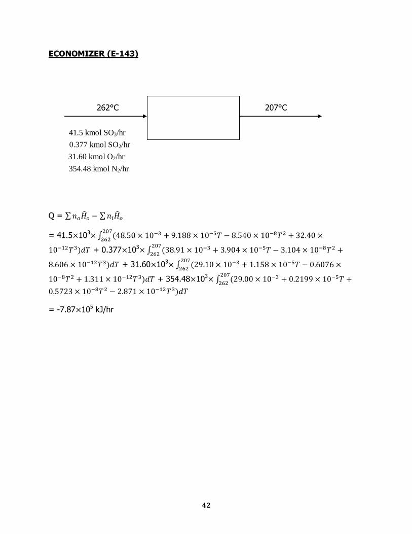
ECONOMIZER (E-143)
262°C 207°C
Q =
= 41.5 103
+ 0.377 103
+ 31.60 103
+ 354.48 103
= -7.87 105 kJ/hr
41.5 kmol SO3/hr
0.377 kmol SO2/hr
31.60 kmol O2/hr
354.48 kmol N2/hr
43
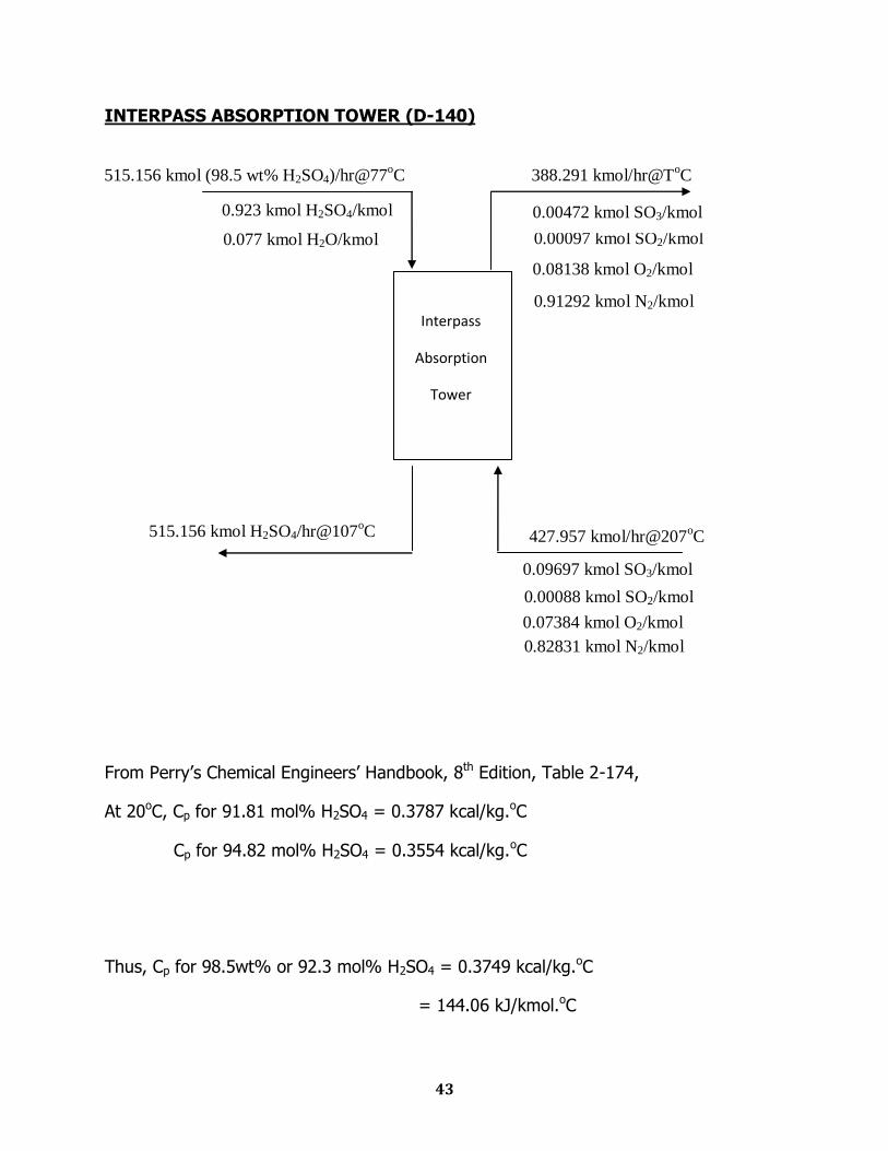
INTERPASS ABSORPTION TOWER (D-140)
From Perry‟s Chemical Engineers‟ Handbook, 8th Edition, Table 2-174,
At 20oC, Cp for 91.81 mol% H2SO4 = 0.3787 kcal/kg.oC
Cp for 94.82 mol% H2SO4 = 0.3554 kcal/kg.oC
Thus, Cp for 98.5wt% or 92.3 mol% H2SO4 = 0.3749 kcal/kg.oC
= 144.06 kJ/kmol.oC
515.156 kmol (98.5 wt% H2SO4)/hr@77oC 388.291 kmol/hr@T
oC
0.08138 kmol O2/kmol
0.00097 kmol SO2/kmol
0.00472 kmol SO3/kmol
0.91292 kmol N2/kmol
0.077 kmol H2O/kmol
0.923 kmol H2SO4/kmol
Interpass
Absorption
Tower
427.957 kmol/hr@207oC
515.156 kmol H2SO4/hr@107oC
0.09697 kmol SO3/kmol
0.00088 kmol SO2/kmol
0.07384 kmol O2/kmol
0.82831 kmol N2/kmol
44
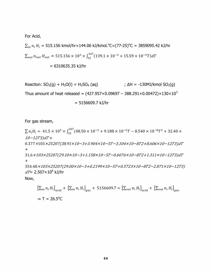
For Acid,
= 515.156 kmol/hr 144.06 kJ/kmol.oC (77-25)oC = 3859095.42 kJ/hr
=
= 6310635.35 kJ/hr
Reaction: SO3(g) + H2O(l) = H2SO4 (aq) ; ∆H = -130MJ/kmol SO3(g)
Thus amount of heat released = (427.957×0.09697 – 388.291×0.00472)×130×103
= 5156609.7 kJ/hr
For gas stream,
10−12 3) +
0.377×103×25207(38.91×10⁻³+3.904×10⁻⁵ −3.104×10⁻⁸ 2+8.606×10⁻¹² 3)
+
31.6×103×25207(29.10×10⁻³+1.158×10⁻⁵ −0.6076×10⁻⁸ 2+1.311×10⁻¹² 3)
+
354.48×103×25207(29.00×10⁻³+0.2199×10⁻⁵ +0.5723×10⁻⁸ 2−2.871×10⁻¹² 3)
= 2.507×10⁶ kJ/hr
Now,
T = 26.5oC
45
FINAL ABSORPTION TOWER (D-150)
From Perry‟s Chemical Engineers‟ Handbook, 8th Edition, Table 2-174,
At 20oC, Cp for 91.81 mol% H2SO4 = 0.3787 kcal/kg.oC
Cp for 94.82 mol% H2SO4 = 0.3554 kcal/kg.oC
Thus, Cp for 98.5wt% or 92.3 mol% H2SO4 = 0.3749 kcal/kg.oC
= 144.06 kJ/kmol.oC
Final
Absorption
Tower
0.923 kmol H2SO4/kmol
0.077 kmol H2O/kmol
0.00538 kmol SO3/kmol
0.00032 kmol SO2/kmol
0.08109 kmol O2/kmol
0.91321 kmol N2/kmol
27.077 kmol (98.5 wt% H2SO4)/hr
27.077 kmol H2SO4/hr
388.168 kmol/hr
0.00000518 kmol SO3/kmol
0.000326 kmol SO2/kmol
0.0815 kmol O2/kmol
0.9181 kmol N2/kmol
386.083 kmol/hr
46
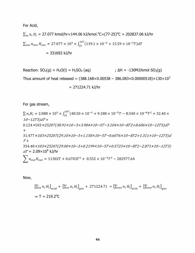
For Acid,
= 27.077 kmol/hr 144.06 kJ/kmol.oC (77-25)oC = 202837.06 kJ/hr
=
= 331692 kJ/hr
Reaction: SO3(g) + H2O(l) = H2SO4 (aq) ; ∆H = -130MJ/kmol SO3(g)
Thus amount of heat released = (388.168×0.00538 – 386.083×0.00000518)×130×103
= 271224.71 kJ/hr
For gas stream,
10−12 3) +
0.124×103×25207(38.91×10⁻³+3.904×10⁻⁵ −3.104×10⁻⁸ 2+8.606×10⁻¹² 3)
+
31.477×103×25207(29.10×10⁻³+1.158×10⁻⁵ −0.6076×10⁻⁸ 2+1.311×10⁻¹² 3)
+
354.48×103×25207(29.00×10⁻³+0.2199×10⁻⁵ +0.5723×10⁻⁸ 2−2.871×10⁻¹² 3)
= 2.09×10⁶ kJ/hr
Now,
T = 219.2oC
47
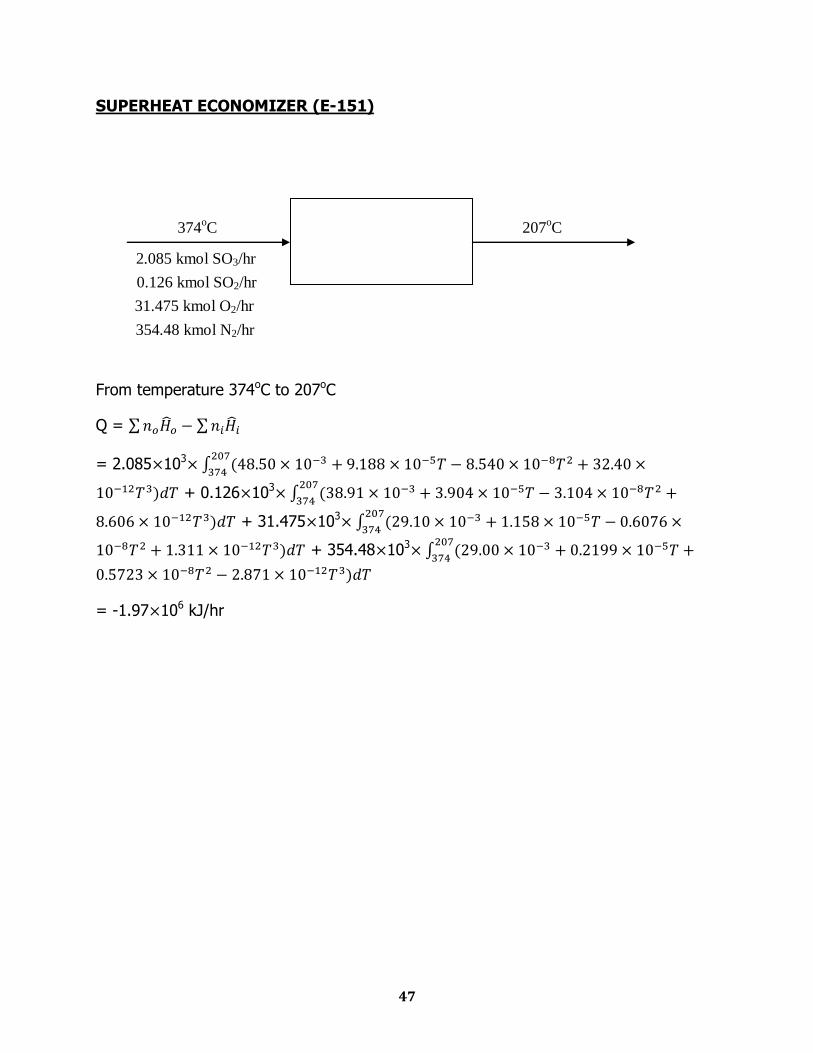
SUPERHEAT ECONOMIZER (E-151)
From temperature 374oC to 207oC
Q =
= 2.085 103
+ 0.126 103
+ 31.475 103
+ 354.48 103
= -1.97 106 kJ/hr
207oC 374
oC
2.085 kmol SO3/hr
0.126 kmol SO2/hr
31.475 kmol O2/hr
354.48 kmol N2/hr
48
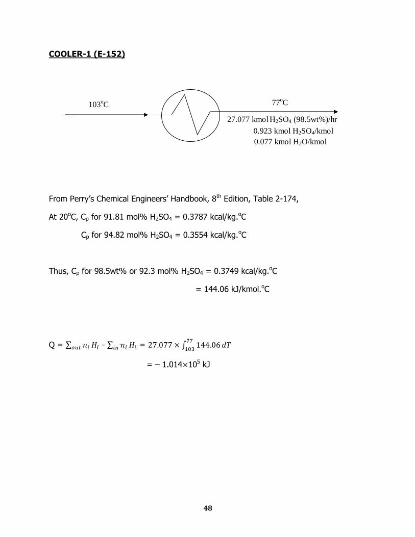
COOLER-1 (E-152)
From Perry‟s Chemical Engineers‟ Handbook, 8th Edition, Table 2-174,
At 20oC, Cp for 91.81 mol% H2SO4 = 0.3787 kcal/kg.oC
Cp for 94.82 mol% H2SO4 = 0.3554 kcal/kg.oC
Thus, Cp for 98.5wt% or 92.3 mol% H2SO4 = 0.3749 kcal/kg.oC
= 144.06 kJ/kmol.oC
Q = - =
= – 1.014 105 kJ
103oC 77
oC
27.077 kmol H2SO4 (98.5wt%)/hr
0.923 kmol H2SO4/kmol
0.077 kmol H2O/kmol
49
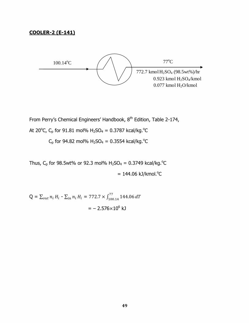
COOLER-2 (E-141)
From Perry‟s Chemical Engineers‟ Handbook, 8th Edition, Table 2-174,
At 20oC, Cp for 91.81 mol% H2SO4 = 0.3787 kcal/kg.oC
Cp for 94.82 mol% H2SO4 = 0.3554 kcal/kg.oC
Thus, Cp for 98.5wt% or 92.3 mol% H2SO4 = 0.3749 kcal/kg.oC
= 144.06 kJ/kmol.oC
Q = - =
= – 2.576 106 kJ
100.14oC 77
oC
772.7 kmol H2SO4 (98.5wt%)/hr
0.923 kmol H2SO4/kmol
0.077 kmol H2O/kmol

50
COOLER-3 (E-162)
From Perry‟s Chemical Engineers‟ Handbook, 8th Edition, Table 2-174,
At 20oC, Cp for 91.81 mol% H2SO4 = 0.3787 kcal/kg.oC
Cp for 94.82 mol% H2SO4 = 0.3554 kcal/kg.oC
Thus, Cp for 98.5wt% or 92.3 mol% H2SO4 = 0.3749 kcal/kg.oC
= 144.06 kJ/kmol.oC
Q = - =
= – 4.444 105 kJ
100.14oC 32
oC
45.273 kmol H2SO4 (98.5wt%)/hr
0.923 kmol H2SO4/kmol
0.077 kmol H2O/kmol
51
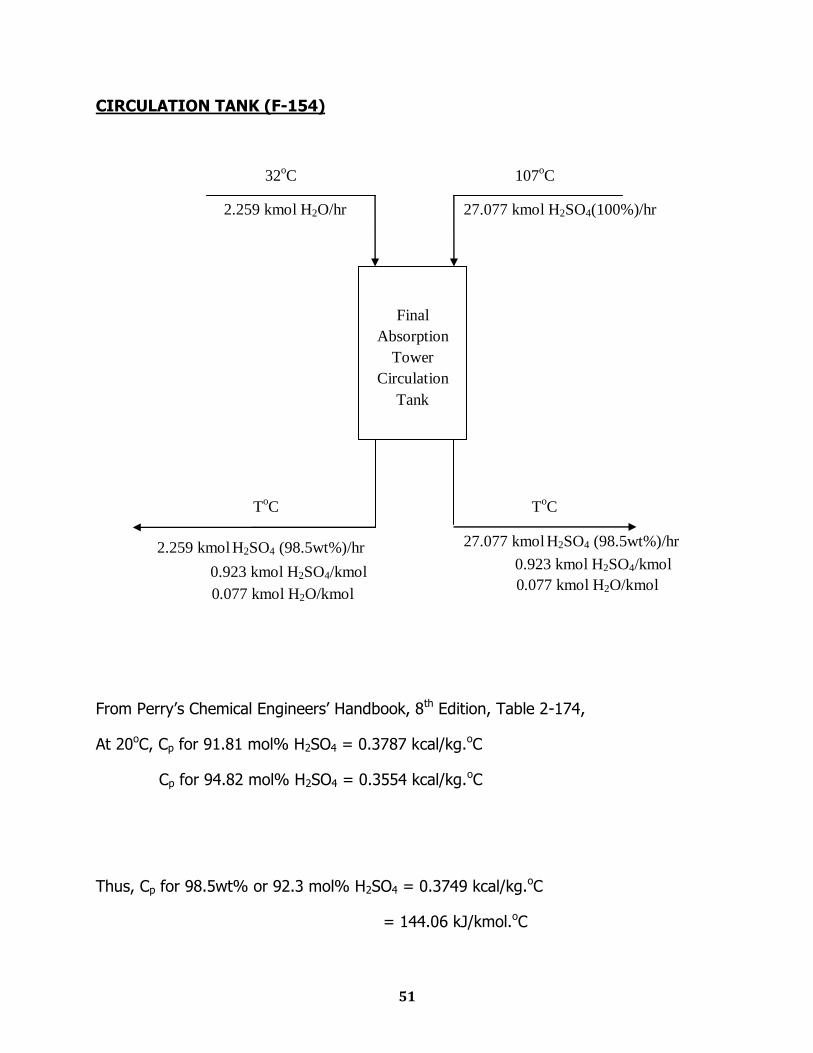
CIRCULATION TANK (F-154)
From Perry‟s Chemical Engineers‟ Handbook, 8th Edition, Table 2-174,
At 20oC, Cp for 91.81 mol% H2SO4 = 0.3787 kcal/kg.oC
Cp for 94.82 mol% H2SO4 = 0.3554 kcal/kg.oC
Thus, Cp for 98.5wt% or 92.3 mol% H2SO4 = 0.3749 kcal/kg.oC
= 144.06 kJ/kmol.oC
2.259 kmol H2O/hr
ToC
107oC 32
oC
27.077 kmol H2SO4(100%)/hr
2.259 kmol H2SO4 (98.5wt%)/hr
0.923 kmol H2SO4/kmol
0.077 kmol H2O/kmol
27.077 kmol H2SO4 (98.5wt%)/hr
0.923 kmol H2SO4/kmol
0.077 kmol H2O/kmol
Final
Absorption
Tower
Circulation
Tank
ToC
52
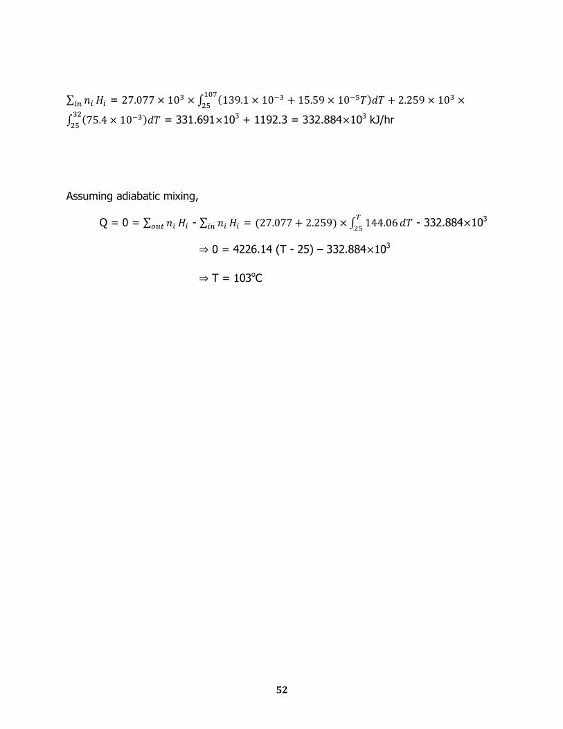
=
= 331.691 103 + 1192.3 = 332.884 103 kJ/hr
Assuming adiabatic mixing,
Q = 0 = - =
- 332.884 103
0 = 4226.14 (T - 25) – 332.884 103
T = 103oC
53
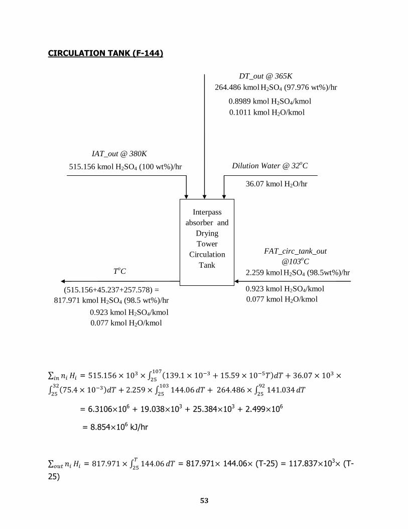
CIRCULATION TANK (F-144)
=
= 6.3106 106 + 19.038 103 + 25.384 103 + 2.499 106
= 8.854 106 kJ/hr
=
= 817.971 144.06 (T-25) = 117.837 103 (T-
25)
36.07 kmol H2O/hr
0.8989 kmol H2SO4/kmol
0.1011 kmol H2O/kmol
DT_out @ 365K
ToC
(515.156+45.237+257.578) =
817.971 kmol H2SO4 (98.5 wt%)/hr
0.923 kmol H2SO4/kmol
0.077 kmol H2O/kmol
IAT_out @ 380K
515.156 kmol H2SO4 (100 wt%)/hr
FAT_circ_tank_out
@103oC
0.923 kmol H2SO4/kmol
0.077 kmol H2O/kmol
2.259 kmol H2SO4 (98.5wt%)/hr
Dilution Water @ 32oC
Interpass
absorber and
Drying
Tower
Circulation
Tank
264.486 kmol H2SO4 (97.976 wt%)/hr
54
Assuming adiabatic mixing,
Q = 0 = - = 117.837 103 (T-25) - 8.854 106
0 = 117.837 103 (T-25) - 8.854 106
T = 100.14oC

Chapter Eight
Water & Steam Balance
56
WASTE HEAT BOILER-1 (E-131)
Ground water temp = 20 0 C = 68 0 F
Temperature of steam = 100 0 C = 212 0 F (Let)
Q1 = Q2
6.062 109 = m × S × Δθ + m×
= m × (S × Δθ +
= m × (4200 × (100-20) +
= m × 2593000
m = 2337.83 kg/hr
WASTE HEAT BOILER-2 (E-132)
Ground water temp = 20 0 C = 68 0 F
Temperature of steam = 100 0 C = 212 0 F (Let)
Q1 = Q2
21.273 108 = m × S × Δθ + m×
= m × (S × Δθ +
= m × (4200 × (100-20) +
= m × 2593000
m = 820.4 kg/hr
57
ECONOMIZER (E-143)
Ground water temp = 20 0 C = 68 0 F
Temperature of water = 80 0 C = 176 0 F (Let)
Q1 = Q2
7.87 108 = m × S × Δθ
= m × S × Δθ
= m × 4200 × (80-20)
= m × 252000
m = 3123 kg/hr
SUPERHEAT ECONOMIZER (E-151)
Inlet steam temp = 100 0 C
Temperature of outlet steam = 150 0 C (Let)
Q1 = Q2
1.97 106 = m × S × Δθ
m ×2100 × (150 – 100) = 1.97 106
m = 18.76 kg/hr.
58
COOLER-1 (E-152)
Ground water temp = 20 0 C
Temperature of water = 35 0 C
1.014 108= m Δθ
= m (35-20)
m = 1609.52 kg/hr
COOLER-2 (E-141)
Ground water temp = 20 0 C
Temperature of water = 70 0 C
2.576 109 = m Δθ
= m (70-20)
m = 12266.66 kg/hr
COOLER-3 (E-162)
Ground water temp = 20 0 C
Temperature of water = 50 0 C
4.444 108 = m Δθ
= m (50-20)
m = 3526.98 kg/hr

Chapter Nine
Power Balance
60
BLOWER (G-112)
Blower outlet pressure = 2 atm
Assuming isothermal compression
Work = nRT ln(P2/P1)
= 449.145×1000 mol air/hr × 8.314JK-1mol-1 × 310K × ln(2/1)
= 802.386×10⁶ J/hr
= 222885 J/s
= 298.77 hP
61
PUMP-1 (L-122)
Density of Liquid Sulfur = 1.819 g/cm3 = 1819 kg/m3
Flow rate of liquid sulfur = 41.88 kmol/hr
= 1340.16 kg/hr
Viscosity of liquid sulfur at 140oC = 7.52 cP
Volumetric flow rate of liquid sulfur = 0.737 m3/hr
Assuming 2in nominal pipe size and 40 schedule number.
Internal dia for 4in nominal size pipe = 2.067 in =0.053 m
Total power head,
Wo=g∆Z+∆p/ρ+ΣF
Sum ΣF =
Reynolds no,
Re = ρ
=
= 121
Mass flow rate,
m= 0.3722 Kg/s
Volumetric flow rate,
Q=0.377/1819 = 0.0002 m3/s
Area, A=
=
=0.0022 m2
Velocity, V=Q/A
=
= 0.093 m/s
62
Friction factor,
f=
=0.1322
Equivalent length,
L=2 m
ΣF=
=0.030 J/kg
Here, ∆p/ρ=0
Elevation Head,
∆Z=1.5 m
Total power head,
Wo=9.8*1.5+0.030
=14.745 J/kg
Hence total H.P=14.745x0.3722/746 H.P
=0.01 hp
63
PUMP-2 (L-153)
Using Nomograph for the estimation of optimum economic pipe dia = 4 in
Thus we will select pipe with 4in nominal pipe size and 40 schedule number.
Internal dia for 4in nominal size pipe = 4.026 in =0.1023m
Total power head,
Wo=g∆Z+∆p/ρ+ΣF
Sum ΣF =
Reynolds no,
Re = ρ
=
=318
Mass flow rate,
m=27.077 x 0.923 x1000x98x10-3/3600
=0.68 Kg/s
Volumetric flow rate,
Q=0.68/1825 = 3.72 x 10⁻⁴ m3/s
Area, A=
=
=8.1x 10⁻³ m2
Velocity, V=Q/A
=
= 4.6 x 10⁻² m/s
Friction factor,
f=
=0.051
64
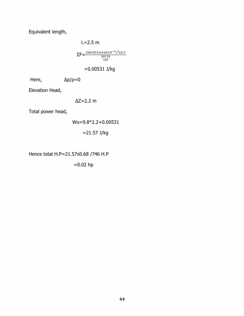
Equivalent length,
L=2.5 m
ΣF=
=0.00531 J/kg
Here, ∆p/ρ=0
Elevation Head,
∆Z=2.2 m
Total power head,
Wo=9.8*2.2+0.00531
=21.57 J/kg
Hence total H.P=21.57x0.68 /746 H.P
=0.02 hp
65
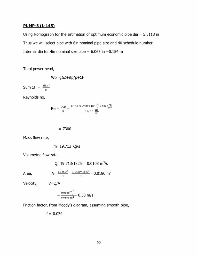
PUMP-3 (L-145)
Using Nomograph for the estimation of optimum economic pipe dia = 5.5118 in
Thus we will select pipe with 6in nominal pipe size and 40 schedule number.
Internal dia for 4in nominal size pipe = 6.065 in =0.154 m
Total power head,
Wo=g∆Z+∆p/ρ+ΣF
Sum ΣF =
Reynolds no,
Re = ρ
=
= 7300
Mass flow rate,
m=19.713 Kg/s
Volumetric flow rate,
Q=19.713/1825 = 0.0108 m3/s
Area, A=
=
=0.0186 m2
Velocity, V=Q/A
=
= 0.58 m/s
Friction factor, from Moody‟s diagram, assuming smooth pipe,
f = 0.034
66
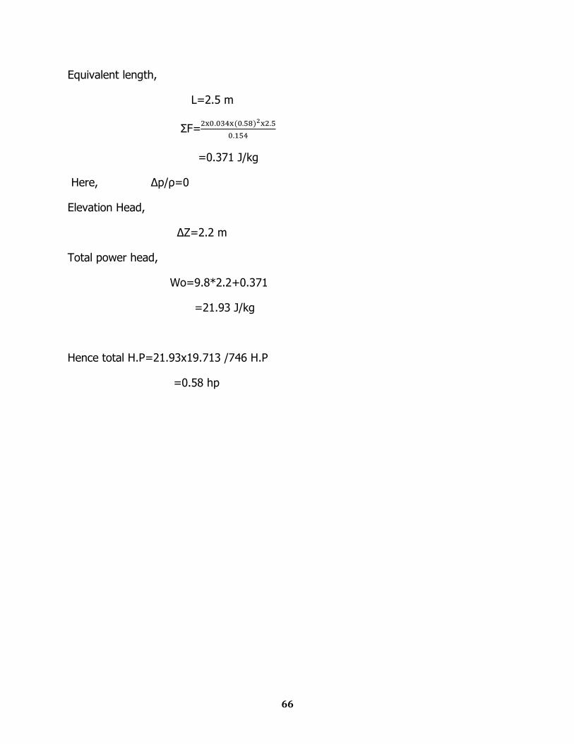
Equivalent length,
L=2.5 m
ΣF=
=0.371 J/kg
Here, ∆p/ρ=0
Elevation Head,
∆Z=2.2 m
Total power head,
Wo=9.8*2.2+0.371
=21.93 J/kg
Hence total H.P=21.93x19.713 /746 H.P
=0.58 hp
67
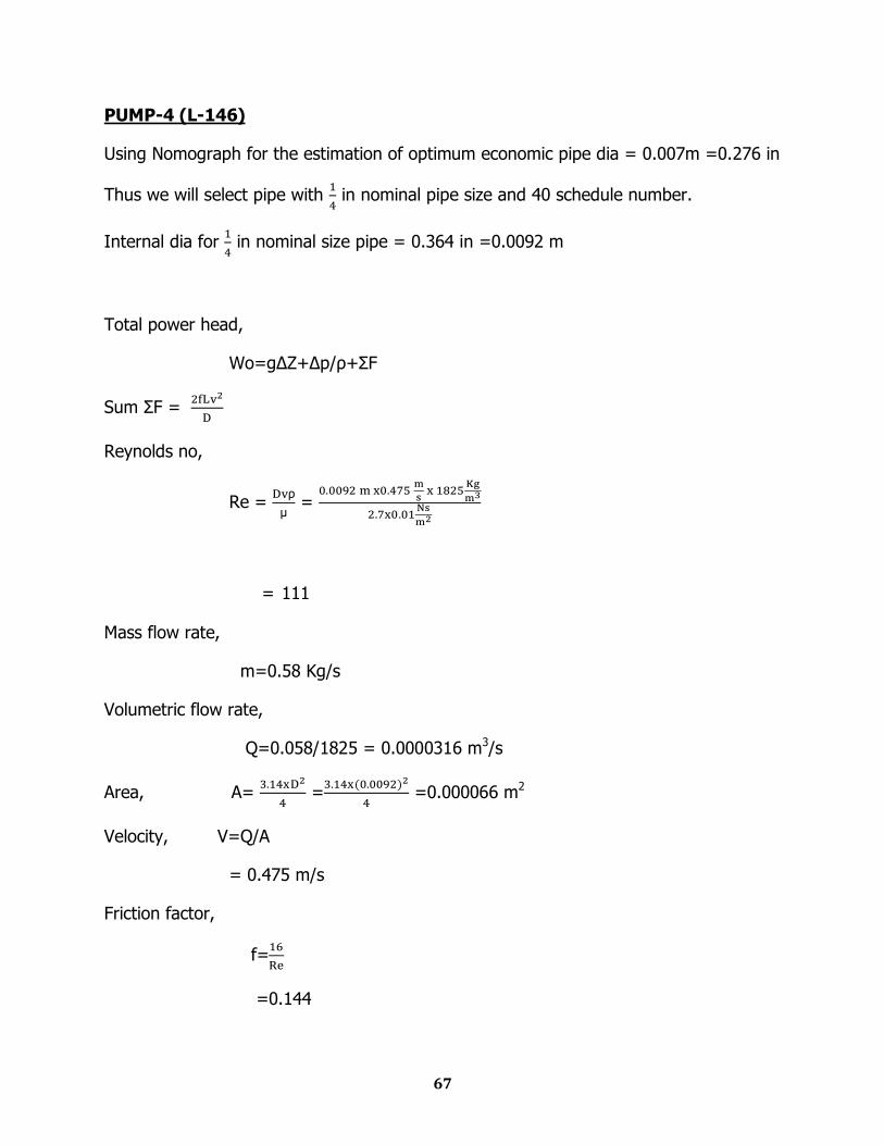
PUMP-4 (L-146)
Using Nomograph for the estimation of optimum economic pipe dia = 0.007m =0.276 in
Thus we will select pipe with
in nominal pipe size and 40 schedule number.
Internal dia for
in nominal size pipe = 0.364 in =0.0092 m
Total power head,
Wo=g∆Z+∆p/ρ+ΣF
Sum ΣF =
Reynolds no,
Re = ρ
=
= 111
Mass flow rate,
m=0.58 Kg/s
Volumetric flow rate,
Q=0.058/1825 = 0.0000316 m3/s
Area, A=
=
=0.000066 m2
Velocity, V=Q/A
= 0.475 m/s
Friction factor,
f=
=0.144
68
Equivalent length,
L=5 m
ΣF=
=35.35 J/kg
Here, ∆p/ρ=0
Elevation Head,
∆Z=4.75 m
Total power head,
Wo=9.8*4.75+35.35
=81.9 J/kg
Hence total H.P=81.9 x 0.58 /746 H.P
=0.1 hp
69
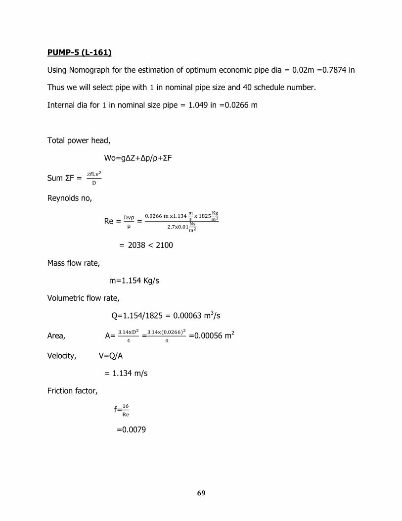
PUMP-5 (L-161)
Using Nomograph for the estimation of optimum economic pipe dia = 0.02m =0.7874 in
Thus we will select pipe with in nominal pipe size and 40 schedule number.
Internal dia for in nominal size pipe = 1.049 in =0.0266 m
Total power head,
Wo=g∆Z+∆p/ρ+ΣF
Sum ΣF =
Reynolds no,
Re = ρ
=
= 2038 < 2100
Mass flow rate,
m=1.154 Kg/s
Volumetric flow rate,
Q=1.154/1825 = 0.00063 m3/s
Area, A=
=
=0.00056 m2
Velocity, V=Q/A
= 1.134 m/s
Friction factor,
f=
=0.0079

70
Equivalent length,
L=11 m
ΣF=
=8.4 J/kg
Here, ∆p/ρ=0
Elevation Head,
∆Z=10 m
Total power head,
Wo=9.8*10 + 8.4
=106.4 J/kg
Hence total H.P=106.4 x 1.154 /746 H.P
=0.164 hp

Chapter Ten
Stream Table
72
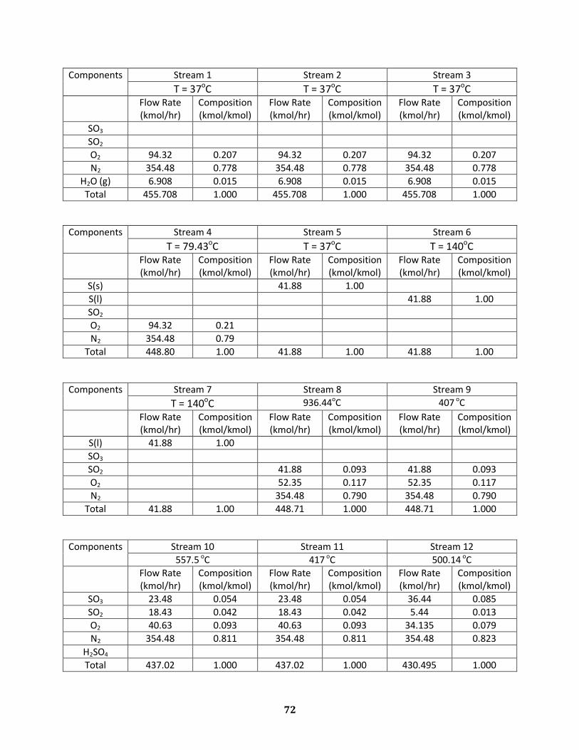
Components Stream 1 Stream 2 Stream 3
T = 37oC T = 37oC T = 37oC
Flow Rate (kmol/hr)
Composition (kmol/kmol)
Flow Rate (kmol/hr)
Composition (kmol/kmol)
Flow Rate (kmol/hr)
Composition (kmol/kmol)
SO3
SO2
O2 94.32 0.207 94.32 0.207 94.32 0.207
N2 354.48 0.778 354.48 0.778 354.48 0.778
H2O (g) 6.908 0.015 6.908 0.015 6.908 0.015
Total 455.708 1.000 455.708 1.000 455.708 1.000
Components Stream 4 Stream 5 Stream 6
T = 79.43oC T = 37oC T = 140oC
Flow Rate (kmol/hr)
Composition (kmol/kmol)
Flow Rate (kmol/hr)
Composition (kmol/kmol)
Flow Rate (kmol/hr)
Composition (kmol/kmol)
S(s) 41.88 1.00
S(l) 41.88 1.00
SO2
O2 94.32 0.21
N2 354.48 0.79
Total 448.80 1.00 41.88 1.00 41.88 1.00
Components Stream 7 Stream 8 Stream 9
T = 140oC 936.44oC 407 oC
Flow Rate (kmol/hr)
Composition (kmol/kmol)
Flow Rate (kmol/hr)
Composition (kmol/kmol)
Flow Rate (kmol/hr)
Composition (kmol/kmol)
S(l) 41.88 1.00
SO3
SO2 41.88 0.093 41.88 0.093
O2 52.35 0.117 52.35 0.117
N2 354.48 0.790 354.48 0.790
Total 41.88 1.00 448.71 1.000 448.71 1.000
Components Stream 10 Stream 11 Stream 12
557.5 oC 417 oC 500.14 oC
Flow Rate (kmol/hr)
Composition (kmol/kmol)
Flow Rate (kmol/hr)
Composition (kmol/kmol)
Flow Rate (kmol/hr)
Composition (kmol/kmol)
SO3 23.48 0.054 23.48 0.054 36.44 0.085
SO2 18.43 0.042 18.43 0.042 5.44 0.013
O2 40.63 0.093 40.63 0.093 34.135 0.079
N2 354.48 0.811 354.48 0.811 354.48 0.823
H2SO4
Total 437.02 1.000 437.02 1.000 430.495 1.000
73
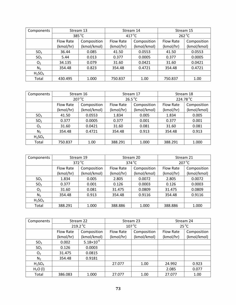
Components Stream 13 Stream 14 Stream 15
385 oC 417 oC 262 oC
Flow Rate (kmol/hr)
Composition (kmol/kmol)
Flow Rate (kmol/hr)
Composition (kmol/kmol)
Flow Rate (kmol/hr)
Composition (kmol/kmol)
SO3 36.44 0.085 41.50 0.0553 41.50 0.0553
SO2 5.44 0.013 0.377 0.0005 0.377 0.0005
O2 34.135 0.079 31.60 0.0421 31.60 0.0421
N2 354.48 0.823 354.48 0.4721 354.48 0.4721
H2SO4
Total 430.495 1.000 750.837 1.00 750.837 1.00
Components Stream 16 Stream 17 Stream 18
207 oC 26.5 oC 224.78 oC
Flow Rate (kmol/hr)
Composition (kmol/kmol)
Flow Rate (kmol/hr)
Composition (kmol/kmol)
Flow Rate (kmol/hr)
Composition (kmol/kmol)
SO3 41.50 0.0553 1.834 0.005 1.834 0.005
SO2 0.377 0.0005 0.377 0.001 0.377 0.001
O2 31.60 0.0421 31.60 0.081 31.60 0.081
N2 354.48 0.4721 354.48 0.913 354.48 0.913
H2SO4
Total 750.837 1.00 388.291 1.000 388.291 1.000
Components Stream 19 Stream 20 Stream 21
372 oC 374 oC 207 oC
Flow Rate (kmol/hr)
Composition (kmol/kmol)
Flow Rate (kmol/hr)
Composition (kmol/kmol)
Flow Rate (kmol/hr)
Composition (kmol/kmol)
SO3 1.834 0.005 2.805 0.0072 2.805 0.0072
SO2 0.377 0.001 0.126 0.0003 0.126 0.0003
O2 31.60 0.081 31.475 0.0809 31.475 0.0809
N2 354.48 0.913 354.48 0.9116 354.48 0.9116
H2SO4
Total 388.291 1.000 388.886 1.000 388.886 1.000
Components Stream 22 Stream 23 Stream 24
219.2 oC 107 oC 25 oC
Flow Rate (kmol/hr)
Composition (kmol/kmol)
Flow Rate (kmol/hr)
Composition (kmol/kmol)
Flow Rate (kmol/hr)
Composition (kmol/kmol)
SO3 0.002 5.18×10⁻⁶
SO2 0.126 0.0003
O2 31.475 0.0815
N2 354.48 0.9181
H2SO4 27.077 1.00 24.992 0.923
H2O (l) 2.085 0.077
Total 386.083 1.000 27.077 1.00 27.077 1.00
74
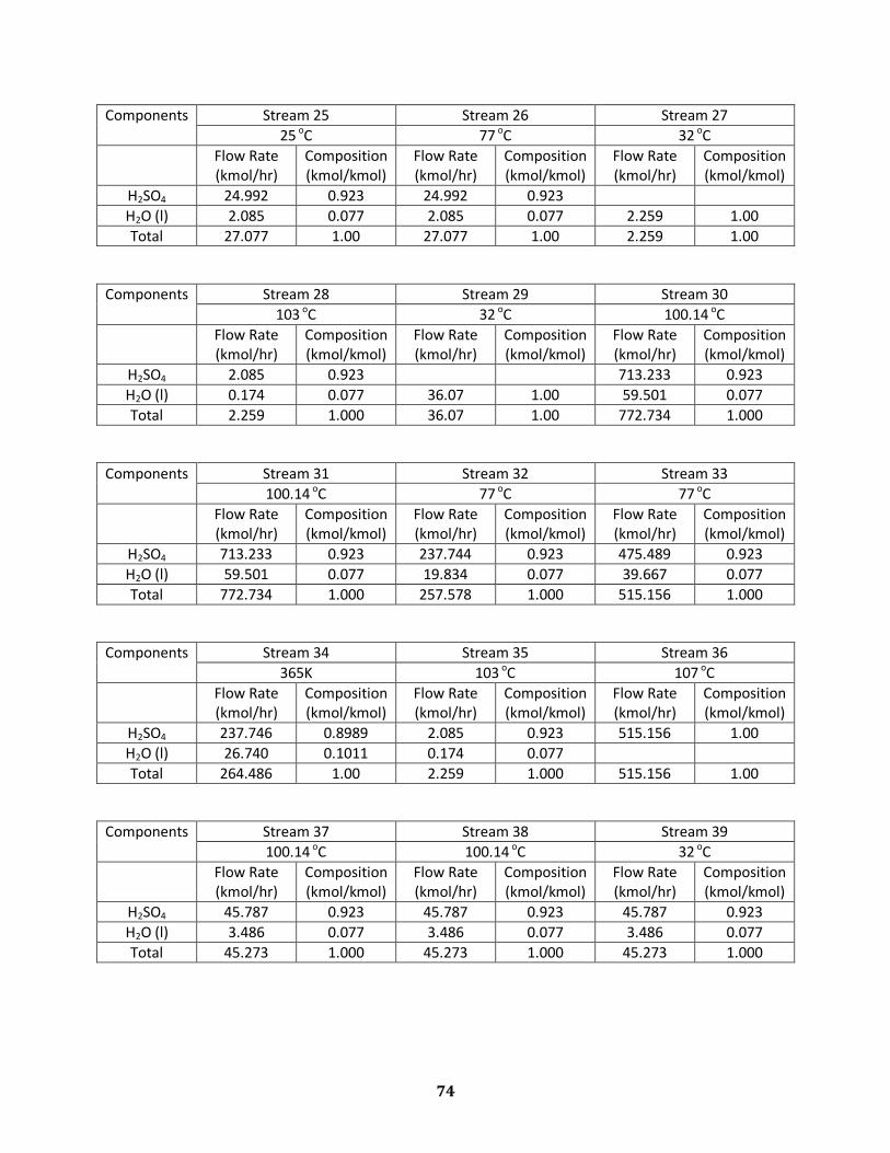
Components Stream 25 Stream 26 Stream 27
25 oC 77 oC 32 oC
Flow Rate (kmol/hr)
Composition (kmol/kmol)
Flow Rate (kmol/hr)
Composition (kmol/kmol)
Flow Rate (kmol/hr)
Composition (kmol/kmol)
H2SO4 24.992 0.923 24.992 0.923
H2O (l) 2.085 0.077 2.085 0.077 2.259 1.00
Total 27.077 1.00 27.077 1.00 2.259 1.00
Components Stream 28 Stream 29 Stream 30
103 oC 32 oC 100.14 oC
Flow Rate (kmol/hr)
Composition (kmol/kmol)
Flow Rate (kmol/hr)
Composition (kmol/kmol)
Flow Rate (kmol/hr)
Composition (kmol/kmol)
H2SO4 2.085 0.923 713.233 0.923
H2O (l) 0.174 0.077 36.07 1.00 59.501 0.077
Total 2.259 1.000 36.07 1.00 772.734 1.000
Components Stream 31 Stream 32 Stream 33
100.14 oC 77 oC 77 oC
Flow Rate (kmol/hr)
Composition (kmol/kmol)
Flow Rate (kmol/hr)
Composition (kmol/kmol)
Flow Rate (kmol/hr)
Composition (kmol/kmol)
H2SO4 713.233 0.923 237.744 0.923 475.489 0.923
H2O (l) 59.501 0.077 19.834 0.077 39.667 0.077
Total 772.734 1.000 257.578 1.000 515.156 1.000
Components Stream 34 Stream 35 Stream 36
365K 103 oC 107 oC
Flow Rate (kmol/hr)
Composition (kmol/kmol)
Flow Rate (kmol/hr)
Composition (kmol/kmol)
Flow Rate (kmol/hr)
Composition (kmol/kmol)
H2SO4 237.746 0.8989 2.085 0.923 515.156 1.00
H2O (l) 26.740 0.1011 0.174 0.077
Total 264.486 1.00 2.259 1.000 515.156 1.00
Components Stream 37 Stream 38 Stream 39
100.14 oC 100.14 oC 32 oC
Flow Rate (kmol/hr)
Composition (kmol/kmol)
Flow Rate (kmol/hr)
Composition (kmol/kmol)
Flow Rate (kmol/hr)
Composition (kmol/kmol)
H2SO4 45.787 0.923 45.787 0.923 45.787 0.923
H2O (l) 3.486 0.077 3.486 0.077 3.486 0.077
Total 45.273 1.000 45.273 1.000 45.273 1.000

Chapter Eleven
Equipment List
76
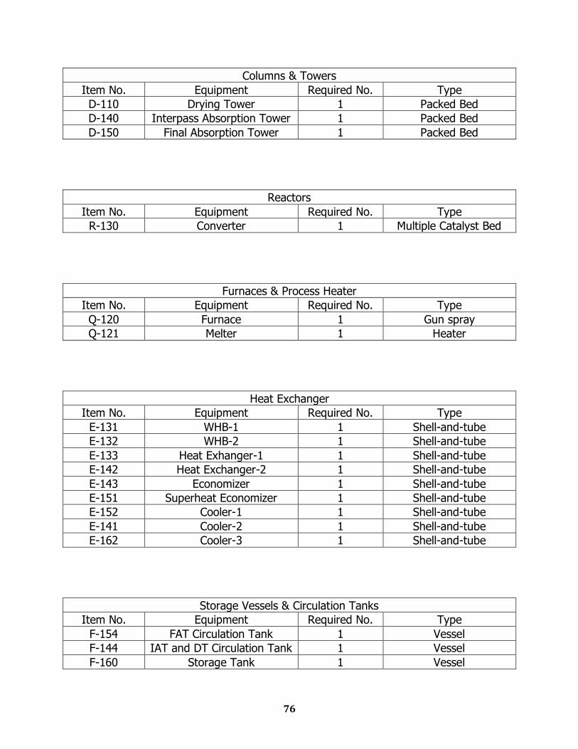
Columns & Towers
Item No. Equipment Required No. Type
D-110 Drying Tower 1 Packed Bed
D-140 Interpass Absorption Tower 1 Packed Bed
D-150 Final Absorption Tower 1 Packed Bed
Reactors
Item No. Equipment Required No. Type
R-130 Converter 1 Multiple Catalyst Bed
Furnaces & Process Heater
Item No. Equipment Required No. Type
Q-120 Furnace 1 Gun spray
Q-121 Melter 1 Heater
Heat Exchanger
Item No. Equipment Required No. Type
E-131 WHB-1 1 Shell-and-tube
E-132 WHB-2 1 Shell-and-tube
E-133 Heat Exhanger-1 1 Shell-and-tube
E-142 Heat Exchanger-2 1 Shell-and-tube
E-143 Economizer 1 Shell-and-tube
E-151 Superheat Economizer 1 Shell-and-tube
E-152 Cooler-1 1 Shell-and-tube
E-141 Cooler-2 1 Shell-and-tube
E-162 Cooler-3 1 Shell-and-tube
Storage Vessels & Circulation Tanks
Item No. Equipment Required No. Type
F-154 FAT Circulation Tank 1 Vessel
F-144 IAT and DT Circulation Tank 1 Vessel
F-160 Storage Tank 1 Vessel
77
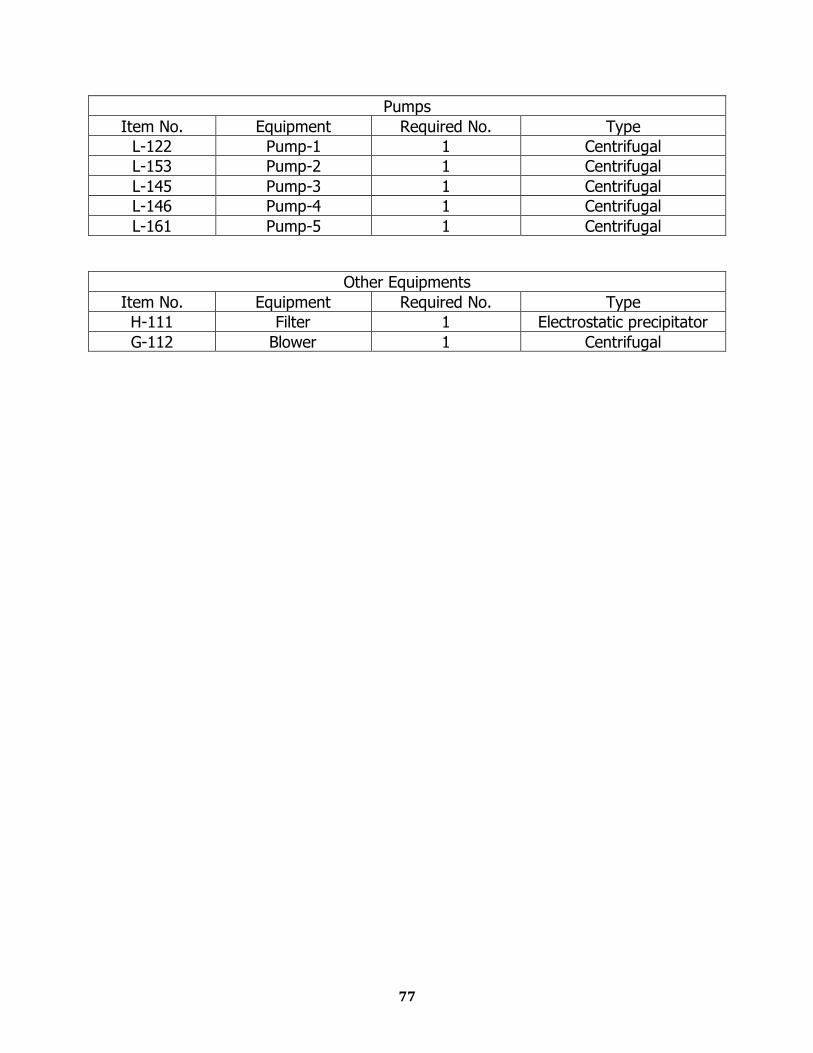
Pumps
Item No. Equipment Required No. Type
L-122 Pump-1 1 Centrifugal
L-153 Pump-2 1 Centrifugal
L-145 Pump-3 1 Centrifugal
L-146 Pump-4 1 Centrifugal
L-161 Pump-5 1 Centrifugal
Other Equipments
Item No. Equipment Required No. Type
H-111 Filter 1 Electrostatic precipitator
G-112 Blower 1 Centrifugal

Chapter Twelve
Equipment Sizing
79
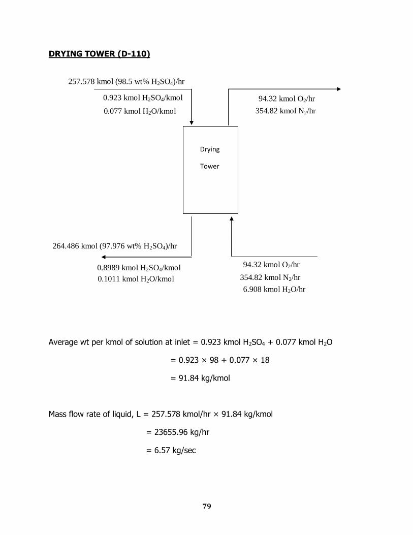
DRYING TOWER (D-110)
Average wt per kmol of solution at inlet = 0.923 kmol H2SO4 + 0.077 kmol H2O
= 0.923 × 98 + 0.077 × 18
= 91.84 kg/kmol
Mass flow rate of liquid, L = 257.578 kmol/hr × 91.84 kg/kmol
= 23655.96 kg/hr
= 6.57 kg/sec
257.578 kmol (98.5 wt% H2SO4)/hr
0.077 kmol H2O/kmol
0.923 kmol H2SO4/kmol
Drying
Tower
264.486 kmol (97.976 wt% H2SO4)/hr
94.32 kmol O2/hr
354.82 kmol N2/hr
6.908 kmol H2O/hr
0.8989 kmol H2SO4/kmol
0.1011 kmol H2O/kmol
94.32 kmol O2/hr
354.82 kmol N2/hr
80
Mass flow rate of gas, G = 6.908×18 + 94.32×32 + 354.82×28
= 13077.544 kg/hr
= 3.6327 kg/sec
Specific Gravity of a 98.5wt % H2SO4 = 1.825 [from „Sulfuric Acid Manufacturing‟ by
Devenport]
Density, ρL = 1.825 × 1000 kg/m3
= 1825 kg/m3
Weight of gas per kmol, M = 0.015×18 + 0.207×32 + 0.778×28
= 28.678 kg/kmol
ρg =
= 0.9986 kg/m3
μL = 5.2 cP [from Devenport]
Packing Material
1.5 inch Ceramic Intalox Saddles
From McCabe Smith,
Bulk density = 39 lb/ft3
Total area = 59 ft2/ft3
Porosity = 0.76
Packing factor, Fp = 52 ft2/ft3
81
Diameter Evaluation
=
= 0.0423
From fig 15-7 [Peters & Timmerhaus, 5th Edition]
= 0.2
G2 =
= 9.4155
G = 3.068 kg/s.m2
v =
= 3.07 m/s
According to the literature, packed column operates at a vapor velocity that is 70% to
90% of the flooding velocity.
Therefore, allowable vapor velocity, v = 0.9 3.07 = 2.763 m/s
Volumetric flow rate of gas =
= 3.638 m3/s
=
=1.3166 m2
=
= 1.295 m
82
Height Evaluation
NTU calculation:
y1 = 0.01515 kmol H2O/kmol
y2 = 0.00001 kmol H2O/kmol
NOG =
But reaction in the interface is so instantaneous that y* = 0
NOG =
= ln
= ln
= 7.323
HTU calculation:
According to the equation developed by Fuller et al. [reference: Coulson & Richardson,
volm 6, 3rd Edition]
Dv =
Ma = molecular weight of H2O = 18
Mb = molecular weight of H2SO4 = 98
T = average H2SO4 temperature = 360K
P = 101325 Pa
Va = Diffusion volume co-efficient for H2O = 1.98 2 + 5.48 = 9.44
Vb = Diffusion volume co-efficient for H2SO4 = 1.98 2 + 17 + 5.48 = 42.88
Dv =
= 0.621×10⁻⁵ m2/s
Gv = Gas phase mass velocity =
= 2.759 kg/m2-s
83
av = Packing surface area per unit volume of packing = 59 ft2/ft3 = 193.57 m2/m3
μv = 2.595 × 10⁻⁵ kg/m-s
According to the correlation of Onda et al. [Ref: Perry‟s Chemical Engineering
Handbook, pp 5-80, table 5-24],
=
Here,
C1 = 5.23
=
= 82.768
=
= 1.611
= = 0.0184
From the correlation,
=
= 5.23 82.768 1.611 0.0184 = 12.832
kG = 12.832 193.57
0.621 10-5
= 0.523 10-3
V =
= 0.107
84
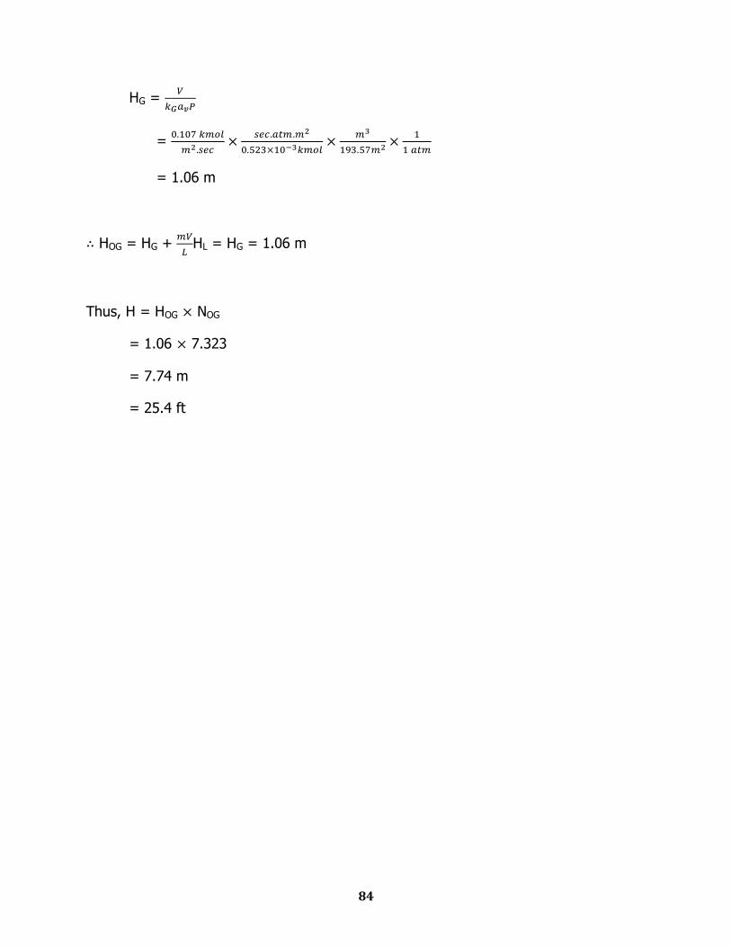
HG =
=
= 1.06 m
HOG = HG +
HL = HG = 1.06 m
Thus, H = HOG NOG
= 1.06 7.323
= 7.74 m
= 25.4 ft
85
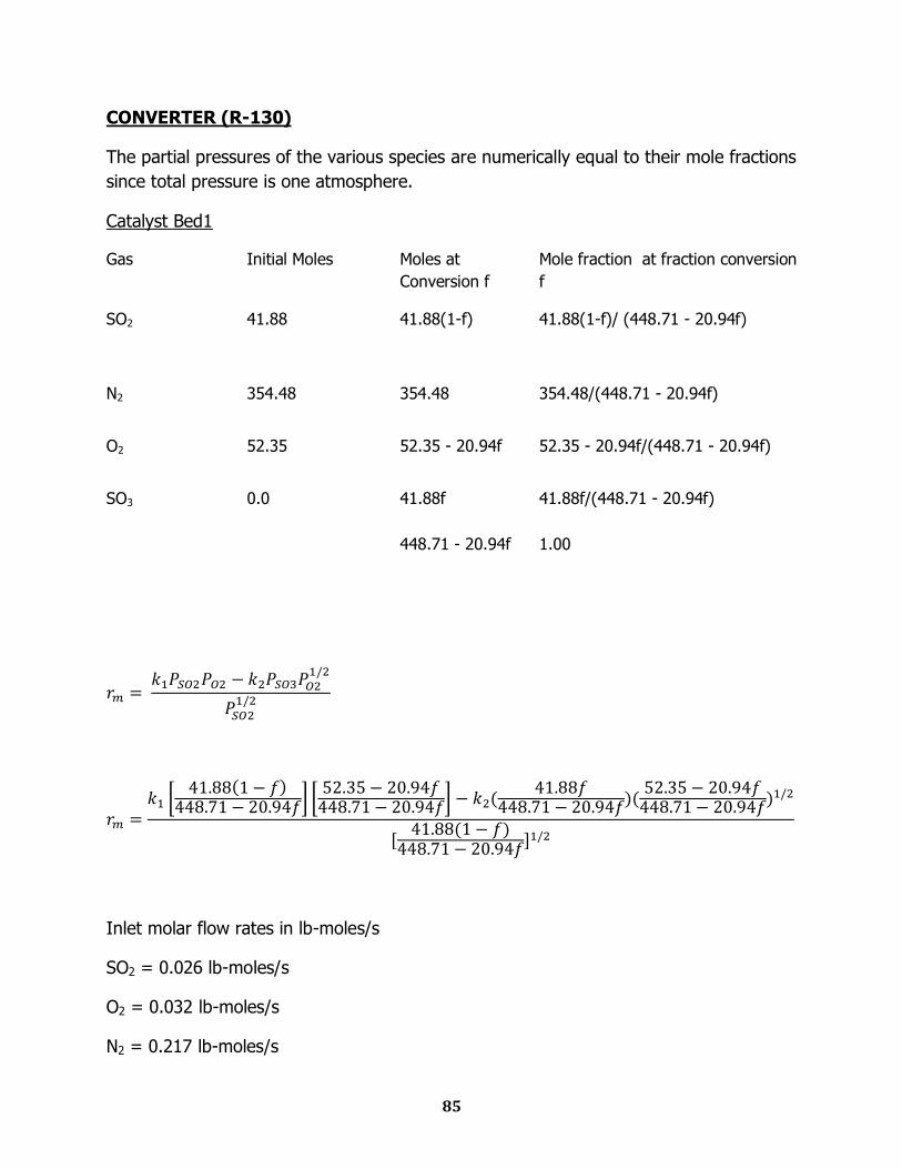
CONVERTER (R-130)
The partial pressures of the various species are numerically equal to their mole fractions
since total pressure is one atmosphere.
Catalyst Bed1
Gas Initial Moles Moles at
Conversion f
Mole fraction at fraction conversion
f
SO2 41.88 41.88(1-f)
41.88(1-f)/ (448.71 - 20.94f)
N2 354.48 354.48 354.48/(448.71 - 20.94f)
O2 52.35 52.35 - 20.94f 52.35 - 20.94f/(448.71 - 20.94f)
SO3 0.0 41.88f 41.88f/(448.71 - 20.94f)
448.71 - 20.94f 1.00
Inlet molar flow rates in lb-moles/s
SO2 = 0.026 lb-moles/s
O2 = 0.032 lb-moles/s
N2 = 0.217 lb-moles/s
86
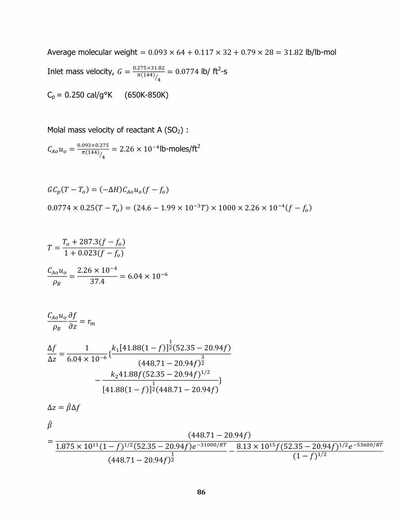
Average molecular weight lb/lb-mol
Inlet mass velocity,
lb/ ft2-s
Cp = 0.250 cal/g°K (650K-850K)
Molal mass velocity of reactant A (SO2) :
lb-moles/ft2

87
Catalyst Bed 1
function [T]= temp1(f); T=(680+(287.3*f))/(1+(0.023*f));
function [b]=beta1(T,f); x=((1.875*10.^11)*(52.35-20.94*f)*(1-f).^0.5)/(((448.71-
20.94*f).^0.5)*exp(15601.4/T)); y=(f*((52.35-20.94*f).^0.5)*(8.13*10.^15))/(((1-f).^0.5)*exp(26975.3/T)); b=(448.71-20.94*f)/(x-y);
function design1 t(1)=680; z(1)=0; for i=1:14 n=i-1; f=0:.04:0.56; if t(i)>860; break end t(i+1)=temp1(f(i+1)); b(i)=beta1(t(i),f(i)); b(i+1)=beta1(t(i+1),f(i+1)); db=0.5*(b(i)+b(i+1)); dz=db*(f(i+1)-f(i)); z(i+1)=z(i)+dz; end disp('data for 1st bed are given below:-') fprintf('%2s\t %2s\t %2s\t %2s\t %2s\t %2s' ,
' f1', 't1', 'z1') fprintf('%s\n', ' ' ) A=[f(1:i+1)',t(1:i+1)',z(1:i+1)']; disp(A)
Data for 1st catalyst bed are given below:
f1 t1 z1
0.00 680.0000 0.0000
0.04 690.8564 0.3070
0.08 701.6929 0.5297
0.12 712.5059 0.6934
0.20 723.3062 0.9071
0.24 744.8405 0.9773
0.28 755.5781 1.0315
f1 t1 z1
0.32 766.2961 1.0740
0.36 776.9945 1.1077
0.40 787.6734 1.1348
0.44 798.3329 1.1571
0.48 808.9729 1.1756
0.52 819.5937 1.1914
0.56 830.1951 1.2054
Outlet temperature = 830K
Conversion = 56% of inlet
Catalyst bed height = 1.21 ft
88
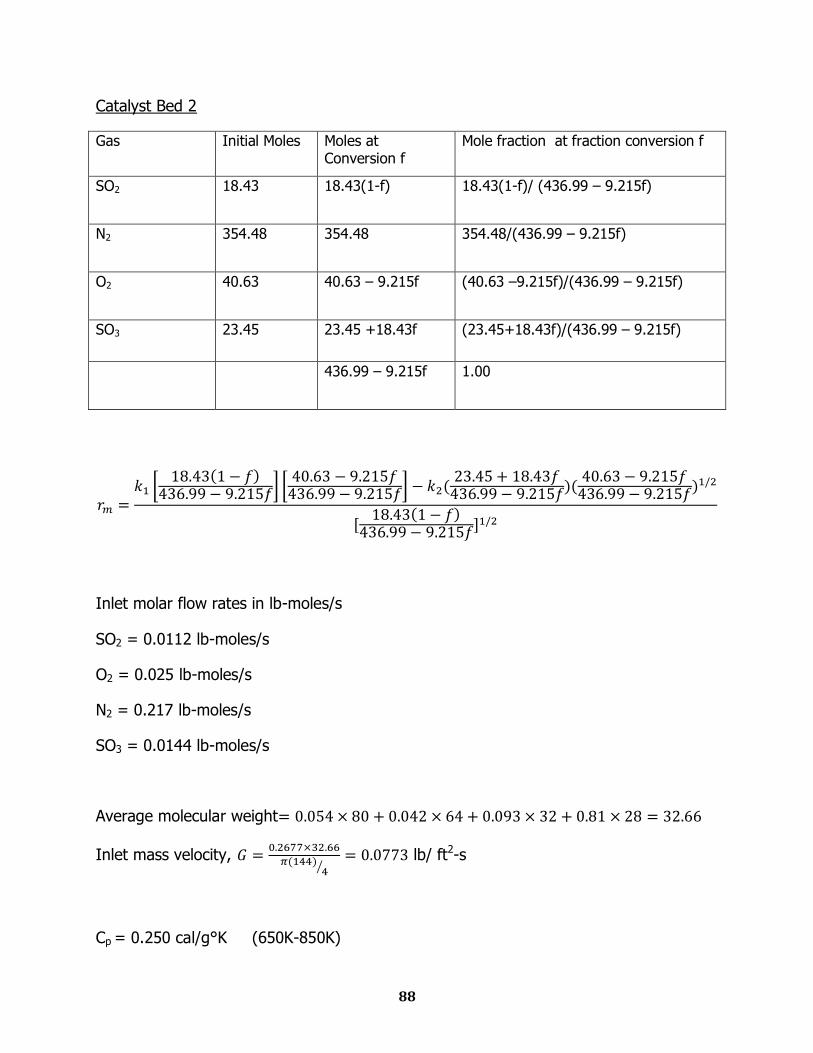
Catalyst Bed 2
Gas Initial Moles Moles at Conversion f
Mole fraction at fraction conversion f
SO2 18.43 18.43(1-f)
18.43(1-f)/ (436.99 – 9.215f)
N2 354.48 354.48 354.48/(436.99 – 9.215f)
O2 40.63 40.63 – 9.215f (40.63 –9.215f)/(436.99 – 9.215f)
SO3 23.45 23.45 +18.43f (23.45+18.43f)/(436.99 – 9.215f)
436.99 – 9.215f 1.00
Inlet molar flow rates in lb-moles/s
SO2 = 0.0112 lb-moles/s
O2 = 0.025 lb-moles/s
N2 = 0.217 lb-moles/s
SO3 = 0.0144 lb-moles/s
Average molecular weight
Inlet mass velocity,
lb/ ft2-s
Cp = 0.250 cal/g°K (650K-850K)
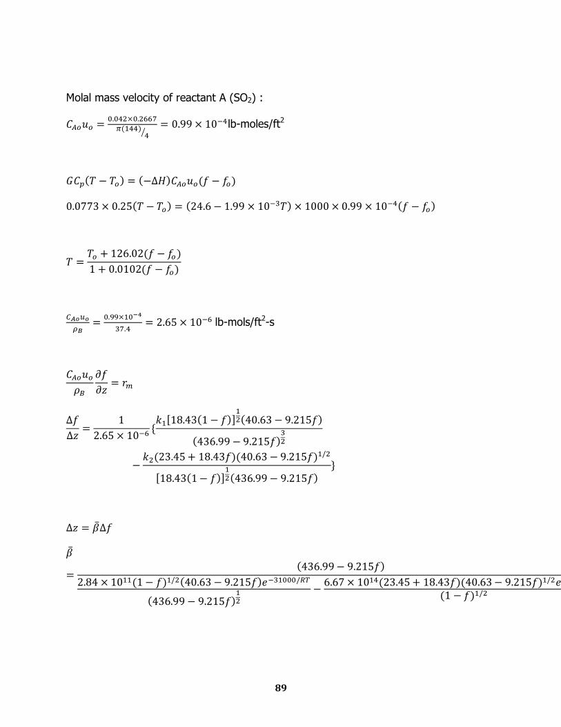
89
Molal mass velocity of reactant A (SO2) :
lb-moles/ft2
lb-mols/ft2-s
90
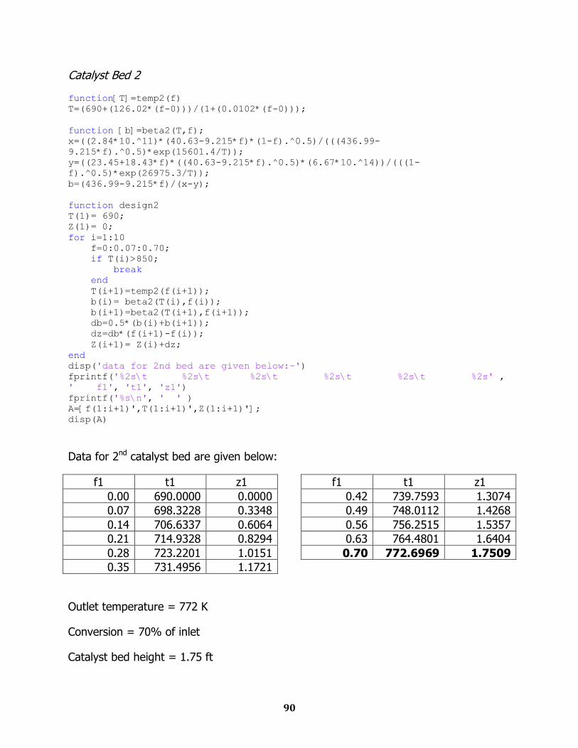
Catalyst Bed 2
function[T]=temp2(f) T=(690+(126.02*(f-0)))/(1+(0.0102*(f-0)));
function [b]=beta2(T,f); x=((2.84*10.^11)*(40.63-9.215*f)*(1-f).^0.5)/(((436.99-
9.215*f).^0.5)*exp(15601.4/T)); y=((23.45+18.43*f)*((40.63-9.215*f).^0.5)*(6.67*10.^14))/(((1-
f).^0.5)*exp(26975.3/T)); b=(436.99-9.215*f)/(x-y);
function design2 T(1)= 690; Z(1)= 0; for i=1:10 f=0:0.07:0.70; if T(i)>850; break end T(i+1)=temp2(f(i+1)); b(i)= beta2(T(i),f(i)); b(i+1)=beta2(T(i+1),f(i+1)); db=0.5*(b(i)+b(i+1)); dz=db*(f(i+1)-f(i)); Z(i+1)= Z(i)+dz; end disp('data for 2nd bed are given below:-') fprintf('%2s\t %2s\t %2s\t %2s\t %2s\t %2s' ,
' f1', 't1', 'z1') fprintf('%s\n', ' ' ) A=[f(1:i+1)',T(1:i+1)',Z(1:i+1)']; disp(A)
Data for 2nd catalyst bed are given below:
f1 t1 z1
0.00 690.0000 0.0000
0.07 698.3228 0.3348
0.14 706.6337 0.6064
0.21 714.9328 0.8294
0.28 723.2201 1.0151
0.35 731.4956 1.1721
f1 t1 z1
0.42 739.7593 1.3074
0.49 748.0112 1.4268
0.56 756.2515 1.5357
0.63 764.4801 1.6404
0.70 772.6969 1.7509
Outlet temperature = 772 K
Conversion = 70% of inlet
Catalyst bed height = 1.75 ft

91
Catalyst Bed 3
Gas Initial Moles Moles at Conversion f Mole fraction at fraction conversion f
SO2 18.43 5.44(1-f)
5.44(1-f)/ (430.50-2.72f)
N2 354.48 354.48 354.48/(430.50-2.72f)
O2 40.63 34.135 – 2.72f (34.135– 2.72f)/( 430.50-2.72f)
SO3 23.45 36.44+5.44f (36.44+5.44f)/( 430.50-2.72f)
430.50-2.72f 1.00
Inlet molar flow rates in lb-moles/s
SO2 = 0.0033 lb-moles/s
O2 = 0.0209 lb-moles/s
N2 = 0.217 lb-moles/s
SO3 = 0.0223 lb-moles/s
Average molecular weight
Inlet mass velocity,
lb/ ft2-s
Cp = 0.250 cal/g°K (650K-850K)
Molal mass velocity of reactant A (SO2) :

92
lb-moles/ft2
lb-mols/ft2-s
93
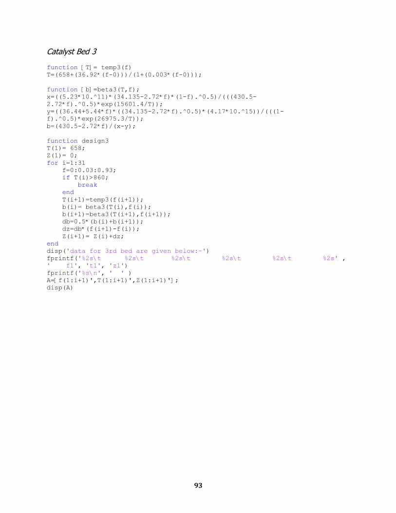
Catalyst Bed 3
function [T]= temp3(f) T=(658+(36.92*(f-0)))/(1+(0.003*(f-0)));
function [b]=beta3(T,f); x=((5.23*10.^11)*(34.135-2.72*f)*(1-f).^0.5)/(((430.5-
2.72*f).^0.5)*exp(15601.4/T)); y=((36.44+5.44*f)*((34.135-2.72*f).^0.5)*(4.17*10.^15))/(((1-
f).^0.5)*exp(26975.3/T)); b=(430.5-2.72*f)/(x-y);
function design3 T(1)= 658; Z(1)= 0; for i=1:31 f=0:0.03:0.93; if T(i)>860; break end T(i+1)=temp3(f(i+1)); b(i)= beta3(T(i),f(i)); b(i+1)=beta3(T(i+1),f(i+1)); db=0.5*(b(i)+b(i+1)); dz=db*(f(i+1)-f(i)); Z(i+1)= Z(i)+dz; end disp('data for 3rd bed are given below:-') fprintf('%2s\t %2s\t %2s\t %2s\t %2s\t %2s' ,
' f1', 't1', 'z1') fprintf('%s\n', ' ' ) A=[f(1:i+1)',T(1:i+1)',Z(1:i+1)']; disp(A)

94
Data for 3rd catalyst bed are given below:
f1 t1 z1
0.00 658.0000 0.0000
0.03 659.0483 0.3047
0.06 660.0964 0.6040
0.09 661.1443 0.8983
0.12 662.1920 1.1879
0.15 663.3340 1.4731
0.18 664.2869 1.7543
0.21 665.3340 2.0319
0.24 666.3810 2.3061
0.27 667.4278 2.5774
0.30 668.4744 2.8462
0.33 669.5208 3.1129
0.36 670.5670 3.3779
0.39 671.6130 3.6418
0.42 672.6588 3.9051
0.45 673.7045 4.1683
f1 t1 z1
0.48 674.7500 4.4323
0.51 675.7952 4.6978
0.54 676.8403 4.9656
0.57 677.8852 5.2370
0.60 678.9299 5.5133
0.63 679.9744 5.7962
0.66 681.0188 6.0880
0.69 682.0629 6.3916
0.72 683.1069 6.7113
0.75 684.1507 7.0532
0.78 685.1942 7.4272
0.81 686.2376 7.8504
0.84 687.2809 8.3578
0.87 688.3239 9.4034
0.90 689.3667 10.4393
0.93 690.4094 10.5245
Outlet temperature = 690 K
Conversion = 93% of inlet
Catalyst bed height = 10.52 ft

95
Catalyst Bed 4
Gas Initial Moles Moles at Conversion f Mole fraction at fraction conversion f
SO2 0.377 0.377(1-f)
0.377(1-f)/ (388.29-0.189f)
N2 354.48 354.48 354.48/(388.29-0.189f)
O2 40.63 31.60 - 0.189f (31.60-0.189f)/(388.29-0.189f)
SO3 23.45 1.834+0.377f (1.834+0.377f)/(388.29-0.189f)
388.29-0.189f 1.00
Inlet molar flow rates in lb-moles/s
SO2 = 0.00023 lb-moles/s
O2 = 0.0194 lb-moles/s
N2 = 0.217 lb-moles/s
SO3 = 0.00112 lb-moles/s
Average molecular weight 0 0047 80 0 00097 64 0 0814 32 0 913 28
28 606
Inlet mass velocity, 0 238 28 606
144 4
0 0602 lb/ ft2-s
Cp = 0.250 cal/g°K (650K-850K)
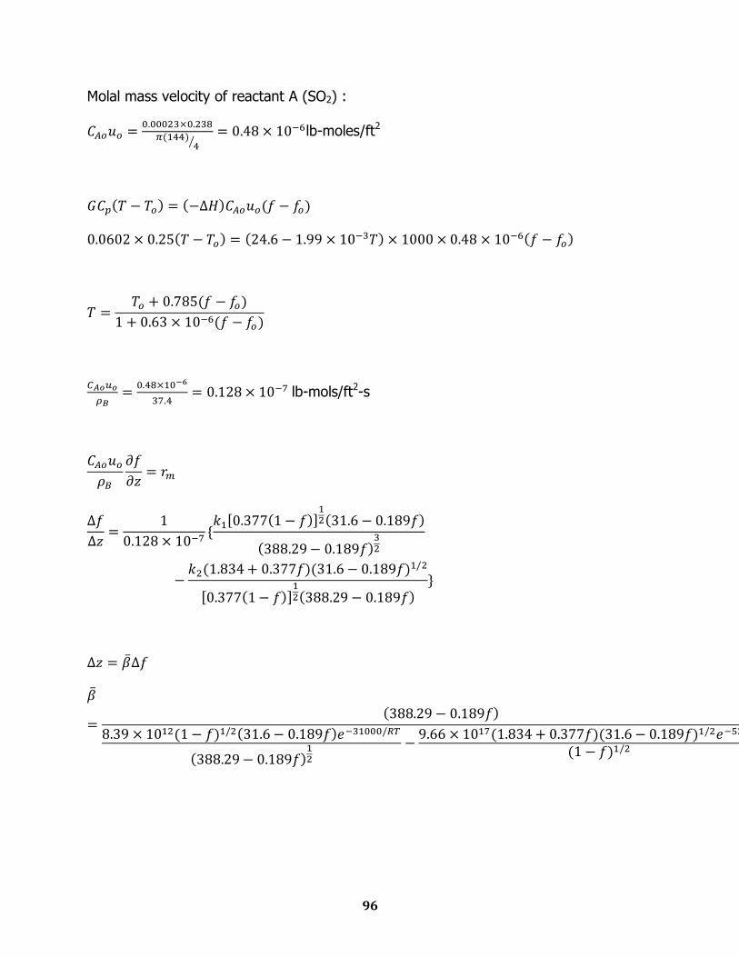
96
Molal mass velocity of reactant A (SO2) :
lb-moles/ft2
lb-mols/ft2-s
97
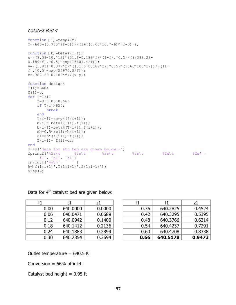
Catalyst Bed 4
function [T]=temp4(f) T=(640+(0.785*(f-0)))/(1+((0.63*10.^-6)*(f-0)));
function [b]=beta4(T,f); x=((8.39*10.^12)*(31.6-0.189*f)*(1-f).^0.5)/(((388.29-
0.189*f).^0.5)*exp(15601.4/T)); y=((1.834+0.377*f)*((31.6-0.189*f).^0.5)*(9.66*10.^17))/(((1-
f).^0.5)*exp(26975.3/T)); b=(388.29-0.189*f)/(x-y);
function design4 T(1)=640; Z(1)=0; for i=1:11 f=0:0.06:0.66; if T(i)>850; break end T(i+1)=temp4(f(i+1)); b(i)= beta4(T(i),f(i)); b(i+1)=beta4(T(i+1),f(i+1)); db=0.5*(b(i)+b(i+1)); dz=db*(f(i+1)-f(i)); Z(i+1)= Z(i)+dz; end disp('data for 4th bed are given below:-') fprintf('%2s\t %2s\t %2s\t %2s\t %2s\t %2s' ,
' f1', 't1', 'z1') fprintf('%s\n', ' ' ) A=[f(1:i+1)',T(1:i+1)',Z(1:i+1)']; disp(A)
Data for 4th catalyst bed are given below:
f1 t1 z1
0.00 640.0000 0.0000
0.06 640.0471 0.0689
0.12 640.0942 0.1400
0.18 640.1412 0.2136
0.24 640.1883 0.2899
0.30 640.2354 0.3694
f1 t1 z1
0.36 640.2825 0.4524
0.42 640.3295 0.5395
0.48 640.3766 0.6314
0.54 640.4237 0.7291
0.60 640.4708 0.8338
0.66 640.5178 0.9473
Outlet temperature = 640.5 K
Conversion = 66% of inlet
Catalyst bed height = 0.95 ft
98
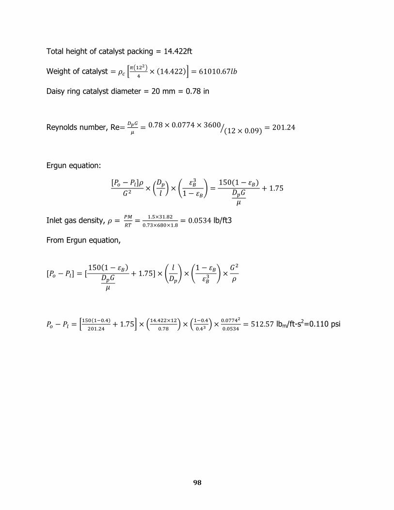
Total height of catalyst packing = 14.422ft
Weight of catalyst
Daisy ring catalyst diameter = 20 mm = 0.78 in
Reynolds number, Re
Ergun equation:
Inlet gas density,
lb/ft3
From Ergun equation,
lbm/ft-s2=0.110 psi
99
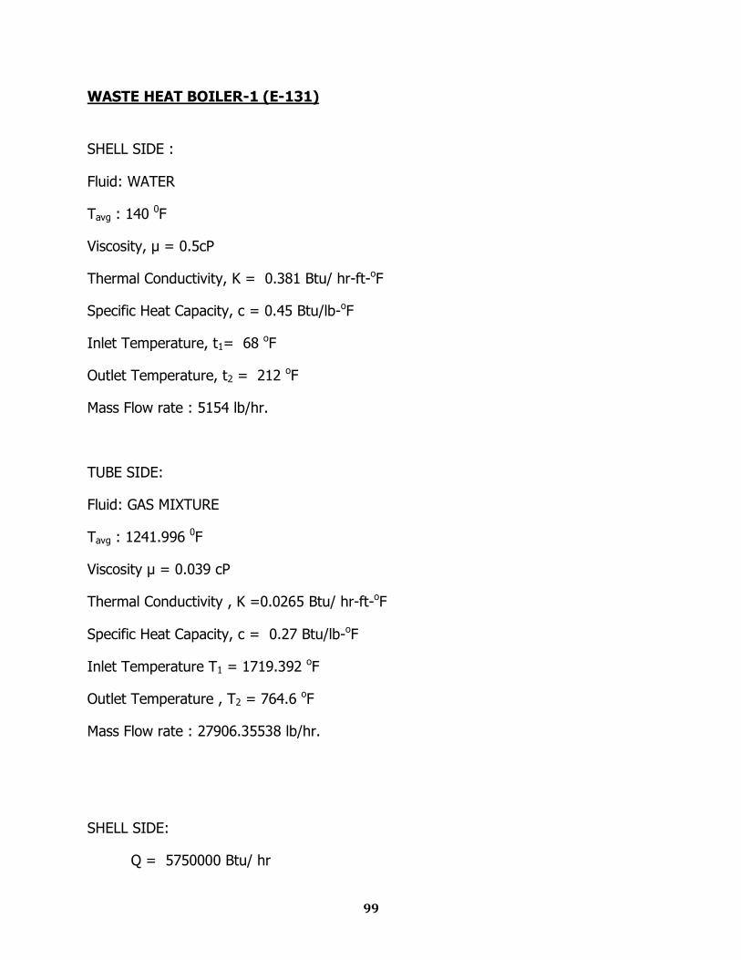
WASTE HEAT BOILER-1 (E-131)
SHELL SIDE :
Fluid: WATER
Tavg : 140 0F
Viscosity, μ = 0.5cP
Thermal Conductivity, K = 0.381 Btu/ hr-ft-oF
Specific Heat Capacity, c = 0.45 Btu/lb-oF
Inlet Temperature, t1= 68 oF
Outlet Temperature, t2 = 212 oF
Mass Flow rate : 5154 lb/hr.
TUBE SIDE:
Fluid: GAS MIXTURE
Tavg : 1241.996 0F
Viscosity μ = 0.039 cP
Thermal Conductivity , K =0.0265 Btu/ hr-ft-oF
Specific Heat Capacity, c = 0.27 Btu/lb-oF
Inlet Temperature T1 = 1719.392 oF
Outlet Temperature , T2 = 764.6 oF
Mass Flow rate : 27906.35538 lb/hr.
SHELL SIDE:
Q = 5750000 Btu/ hr
100
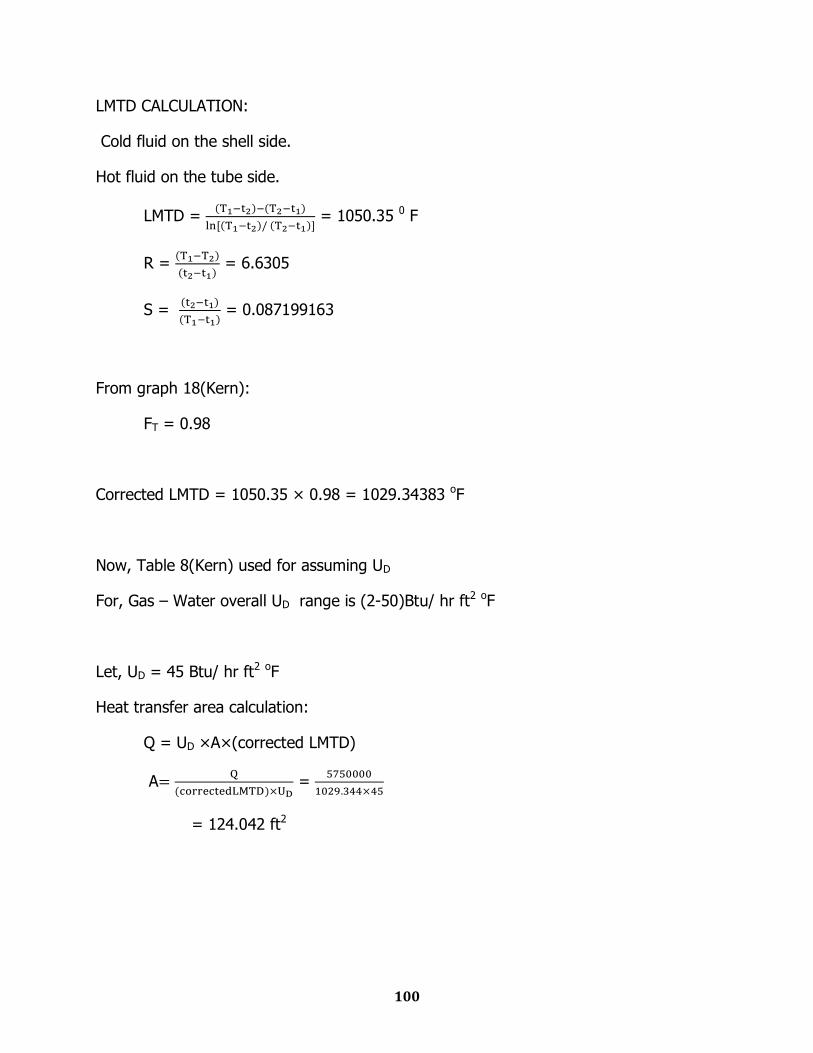
LMTD CALCULATION:
Cold fluid on the shell side.
Hot fluid on the tube side.
LMTD =
= 1050.35 0 F
R =
= 6.6305
S =
= 0.087199163
From graph 18(Kern):
FT = 0.98
Corrected LMTD = 1050.35 × 0.98 = 1029.34383 oF
Now, Table 8(Kern) used for assuming UD
For, Gas – Water overall UD range is (2-50)Btu/ hr ft2 oF
Let, UD = 45 Btu/ hr ft2 oF
Heat transfer area calculation:
Q = UD ×A×(corrected LMTD)
A
=
= 124.042 ft2
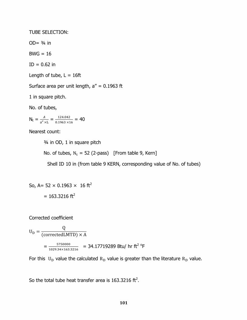
101
TUBE SELECTION:
OD= ¾ in
BWG = 16
ID = 0.62 in
Length of tube, L = 16ft
Surface area per unit length, a‟‟ = 0.1963 ft
1 in square pitch.
No. of tubes,
Nt =
‟‟ =
= 40
Nearest count:
¾ in OD, 1 in square pitch
No. of tubes, = 52 (2-pass) [From table 9, Kern]
Shell ID 10 in (from table 9 KERN, corresponding value of No. of tubes)
So, A= 52 × 0.1963 × 16 ft2
= 163.3216 ft2
Corrected coefficient
=
= 34.17719289 Btu/ hr ft2 oF
For this value the calculated value is greater than the literature value.
So the total tube heat transfer area is 163.3216 ft2.
102
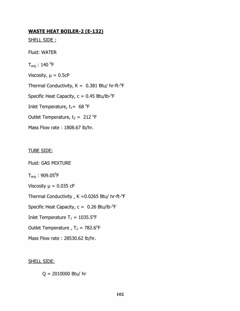
WASTE HEAT BOILER-2 (E-132)
SHELL SIDE :
Fluid: WATER
Tavg : 140 0F
Viscosity, μ = 0.5cP
Thermal Conductivity, K = 0.381 Btu/ hr-ft-oF
Specific Heat Capacity, c = 0.45 Btu/lb-oF
Inlet Temperature, t1= 68 oF
Outlet Temperature, t2 = 212 oF
Mass Flow rate : 1808.67 lb/hr.
TUBE SIDE:
Fluid: GAS MIXTURE
Tavg : 909.050F
Viscosity μ = 0.035 cP
Thermal Conductivity , K =0.0265 Btu/ hr-ft-oF
Specific Heat Capacity, c = 0.26 Btu/lb-oF
Inlet Temperature T1 = 1035.5oF
Outlet Temperature , T2 = 782.6oF
Mass Flow rate : 28530.62 lb/hr.
SHELL SIDE:
Q = 2010000 Btu/ hr

103
LMTD CALCULATION:
Cold fluid on the shell side.
Hot fluid on the tube side.
LMTD =
= 767.760 F
R =
= 1.75625
S =
= 0.148837209
From graph 18(Kern):
FT = 0.98
Corrected LMTD = 767.76 × 0.98 = 752.41 oF
Now, Table 8(Kern) used for assuming UD
For, Gas – Water overall UD range is (2-50)Btu/ hr ft2 oF
Let, UD = 45 Btu/ hr ft2 oF
Heat transfer area calculation
Q = UD ×A×(corrected LMTD)
A
=
= 59.5 ft2
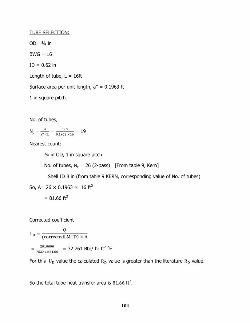
104
TUBE SELECTION:
OD= ¾ in
BWG = 16
ID = 0.62 in
Length of tube, L = 16ft
Surface area per unit length, a‟‟ = 0.1963 ft
1 in square pitch.
No. of tubes,
Nt =
‟‟ =
= 19
Nearest count:
¾ in OD, 1 in square pitch
No. of tubes, = 26 (2-pass) [From table 9, Kern]
Shell ID 8 in (from table 9 KERN, corresponding value of No. of tubes)
So, A= 26 × 0.1963 × 16 ft2
= 81.66 ft2
Corrected coefficient
=
= 32.761 Btu/ hr ft2 oF
For this value the calculated value is greater than the literature value.
So the total tube heat transfer area is ft2.
105
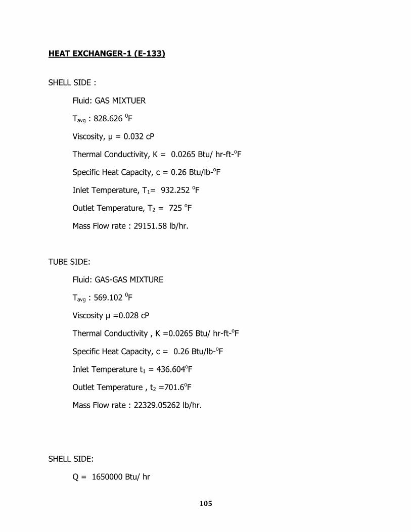
HEAT EXCHANGER-1 (E-133)
SHELL SIDE :
Fluid: GAS MIXTUER
Tavg : 828.626 0F
Viscosity, μ = 0.032 cP
Thermal Conductivity, K = 0.0265 Btu/ hr-ft-oF
Specific Heat Capacity, c = 0.26 Btu/lb-oF
Inlet Temperature, T1= 932.252 oF
Outlet Temperature, T2 = 725 oF
Mass Flow rate : 29151.58 lb/hr.
TUBE SIDE:
Fluid: GAS-GAS MIXTURE
Tavg : 569.102 0F
Viscosity μ =0.028 cP
Thermal Conductivity , K =0.0265 Btu/ hr-ft-oF
Specific Heat Capacity, c = 0.26 Btu/lb-oF
Inlet Temperature t1 = 436.604oF
Outlet Temperature , t2 =701.6oF
Mass Flow rate : 22329.05262 lb/hr.
SHELL SIDE:
Q = 1650000 Btu/ hr

106
LMTD CALCULATION:
Hot fluid on the shell side.
Cold fluid on the tube side.
LMTD =
= 258.4497749 0 F
R =
= 0.782094824
S =
= 0.534645555
From graph 18(Kern):
FT = 0.85
Corrected LMTD = 258.45 × 0.85 = 219.68 oF
Now, Table 8(Kern) used for assuming UD
Over all UD range is (2-50)Btu/ hr ft2 oF
Let, UD = 45 Btu/ hr ft2 oF
Heat transfer area calculation:
Q = UD ×A×(corrected LMTD)
A
=
= 166.616 ft2
107
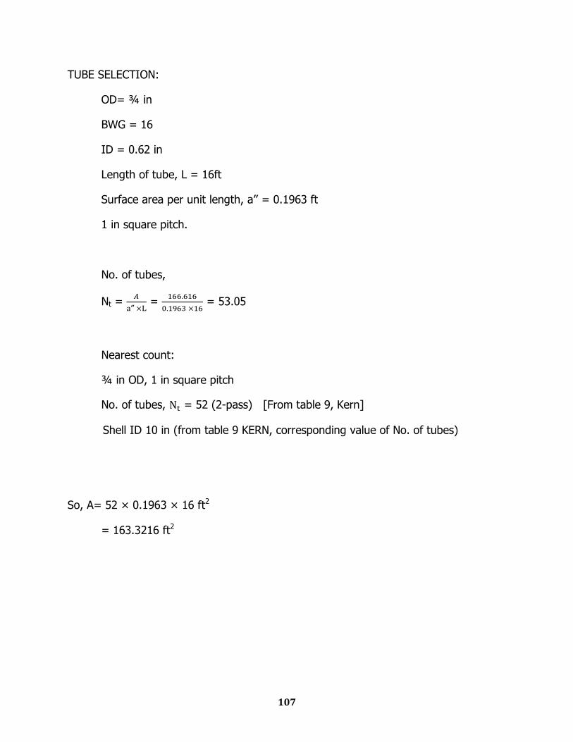
TUBE SELECTION:
OD= ¾ in
BWG = 16
ID = 0.62 in
Length of tube, L = 16ft
Surface area per unit length, a‟‟ = 0.1963 ft
1 in square pitch.
No. of tubes,
Nt =
‟‟ =
= 53.05
Nearest count:
¾ in OD, 1 in square pitch
No. of tubes, = 52 (2-pass) [From table 9, Kern]
Shell ID 10 in (from table 9 KERN, corresponding value of No. of tubes)
So, A= 52 × 0.1963 × 16 ft2
= 163.3216 ft2
108
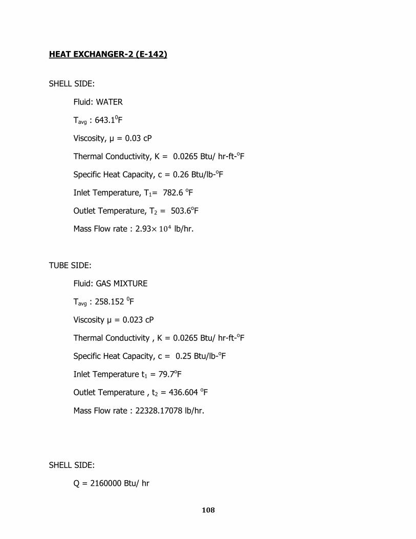
HEAT EXCHANGER-2 (E-142)
SHELL SIDE:
Fluid: WATER
Tavg : 643.10F
Viscosity, μ = 0.03 cP
Thermal Conductivity, K = 0.0265 Btu/ hr-ft-oF
Specific Heat Capacity, c = 0.26 Btu/lb-oF
Inlet Temperature, T1= 782.6 oF
Outlet Temperature, T2 = 503.6oF
Mass Flow rate : 2.93 lb/hr.
TUBE SIDE:
Fluid: GAS MIXTURE
Tavg : 258.152 0F
Viscosity μ = 0.023 cP
Thermal Conductivity , K = 0.0265 Btu/ hr-ft-oF
Specific Heat Capacity, c = 0.25 Btu/lb-oF
Inlet Temperature t1 = 79.7oF
Outlet Temperature , t2 = 436.604 oF
Mass Flow rate : 22328.17078 lb/hr.
SHELL SIDE:
Q = 2160000 Btu/ hr
109
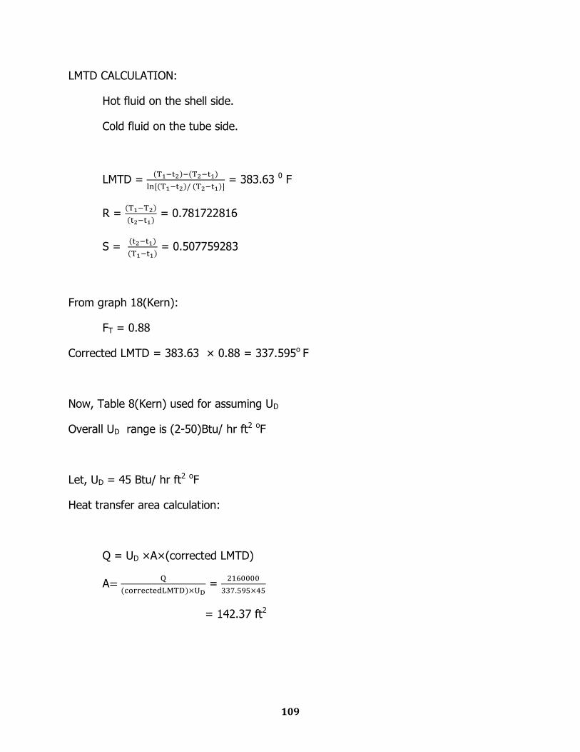
LMTD CALCULATION:
Hot fluid on the shell side.
Cold fluid on the tube side.
LMTD =
= 383.63 0 F
R =
= 0.781722816
S =
= 0.507759283
From graph 18(Kern):
FT = 0.88
Corrected LMTD = 383.63 × 0.88 = 337.595o F
Now, Table 8(Kern) used for assuming UD
Overall UD range is (2-50)Btu/ hr ft2 oF
Let, UD = 45 Btu/ hr ft2 oF
Heat transfer area calculation:
Q = UD ×A×(corrected LMTD)
A
=
= 142.37 ft2
110
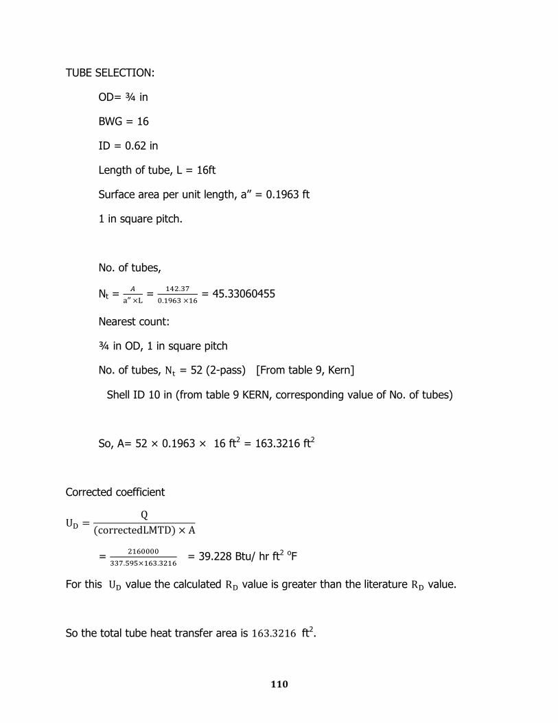
TUBE SELECTION:
OD= ¾ in
BWG = 16
ID = 0.62 in
Length of tube, L = 16ft
Surface area per unit length, a‟‟ = 0.1963 ft
1 in square pitch.
No. of tubes,
Nt =
‟‟ =
= 45.33060455
Nearest count:
¾ in OD, 1 in square pitch
No. of tubes, = 52 (2-pass) [From table 9, Kern]
Shell ID 10 in (from table 9 KERN, corresponding value of No. of tubes)
So, A= 52 × 0.1963 × 16 ft2 = 163.3216 ft2
Corrected coefficient
=
= 39.228 Btu/ hr ft2 oF
For this value the calculated value is greater than the literature value.
So the total tube heat transfer area is ft2.
111
INTERPASS ABSORPTION TOWER (D-140)
Average wt per kmol of solution = 0.923 kmol H2SO4 + 0.077 kmol H2O
= 0.923 × 98 + 0.077 × 18
= 91.84 kg/kmol
Mass flow rate of liquid, L = 515.156 kmol/hr × 91.84 kg/kmol
= 47311.927 kg/hr
= 13.142 kg/sec
Interpass
Absorption
Tower
0.923 kmol H2SO4/kmol
0.077 kmol H2O/kmol
0.09697 kmol SO3/kmol
0.00088 kmol SO2/kmol
0.07384 kmol O2/kmol
0.82831 kmol N2/kmol
515.156 kmol (98.5 wt% H2SO4)/hr
515.156 kmol H2SO4/hr
427.957 kmol/hr
0.00472 kmol SO3/kmol
0.00097 kmol SO2/kmol
0.08138 kmol O2/kmol
0.91292 kmol N2/kmol
388.291 kmol/hr
112
Mass flow rate of gas, G = 427.957 kmol/hr × [0.00088×64 + 0.09697×80 +
0.07384×32 + 0.82831×28]
= 14280.703 kg/hr
= 3.967 kg/sec
Specific Gravity of a 98.5wt % H2SO4 = 1.825 [from „Sulfuric Acid Manufacturing‟ by
Devenport]
Density, ρL = 1.825 × 1000 kg/m3
= 1825 kg/m3
Weight of gas per kmol, M = [0.00088×64 + 0.09697×80 + 0.07384×32 +
0.82831×28]
= 33.3695 kg/kmol
ρg =
= 0.8473 kg/m3
μL = 5.2 cP [from Devenport]
Packing Material:
1.5 inch Ceramic Intalox Saddles
From McCabe Smith,
Bulk density = 39 lb/ft3
Total area = 59 ft2/ft3
Porosity = 0.76
113
Packing factor, Fp = 52 ft2/ft3
Diameter Evaluation:
=
= 0.0714
From fig 15-7 [Peters & Timmerhaus, 5th Edition]
= 0.17
G2 =
= 6.7911
G = 2.606 kg/s.m2
v =
= 3.076 m/s
According to the literature, packed column operates at a vapor velocity that is 70% to
90% of the flooding velocity.
Therefore, allowable vapor velocity, v = 0.9 3.076 = 2.77 m/s
Volumetric flow rate of gas =
= 4.682 m3/s
=
=1.69 m2
=
= 1.467 m
114
Height Evaluation:
NTU calculation:
y1 = 0.09697 kmol SO3/kmol
y2 = 0.00472 kmol SO3/kmol
NOG =
But reaction in the interface is so instantaneous that y* = 0
NOG =
= ln
= ln
= 3.0226
HTU calculation:
According to the equation developed by Fuller et al. [reference: Coulson & Richardson,
volm 6, 3rd Edition]
Dv =
Ma = molecular weight of SO3 = 80
Mb = molecular weight of water = 18
T = average water temperature = 365K
P = 101325 Pa
Va = Diffusion volume co-efficient for SO3 = 17.0 + 5.48 3 = 33.44
Vb = Diffusion volume co-efficient for H2O = 1.98 2 + 5.48 = 9.44
Dv =
= 2.793×10⁻⁵ m2/s
Gv = Gas phase mass velocity =
= 2.36 kg/m2-s

115
av = Packing surface area per unit volume of packing = 59 ft2/ft3 = 193.57 m2/m3
μv = 2.595 × 10⁻⁵ kg/m-s
According to the correlation of Onda et al. [Ref: Perry‟s Chemical Engineering
Handbook, pp 5-80, table 5-24],
=
Here,
C1 = 5.23
=
= 74.19
=
= 1.036
= = 0.0184
From the correlation,
=
= 5.23 74.19 1.036 0.0184 = 7.3966
kG = 7.3966 193.57
2.793 10-5
= 1.336 10-3
V =
= 0.0707
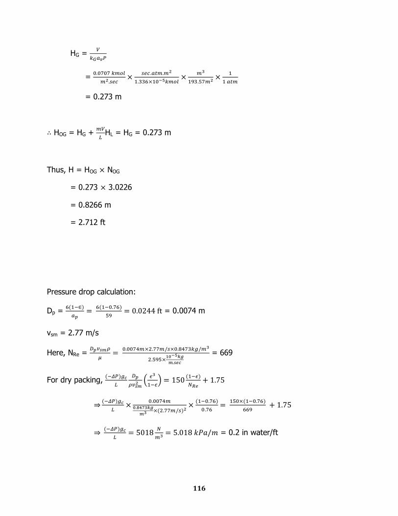
116
HG =
=
= 0.273 m
HOG = HG +
HL = HG = 0.273 m
Thus, H = HOG NOG
= 0.273 3.0226
= 0.8266 m
= 2.712 ft
Pressure drop calculation:
Dp =
= 0.0074 m
vsm = 2.77 m/s
Here, NRe =
= 669
For dry packing,
= 0.2 in water/ft
117
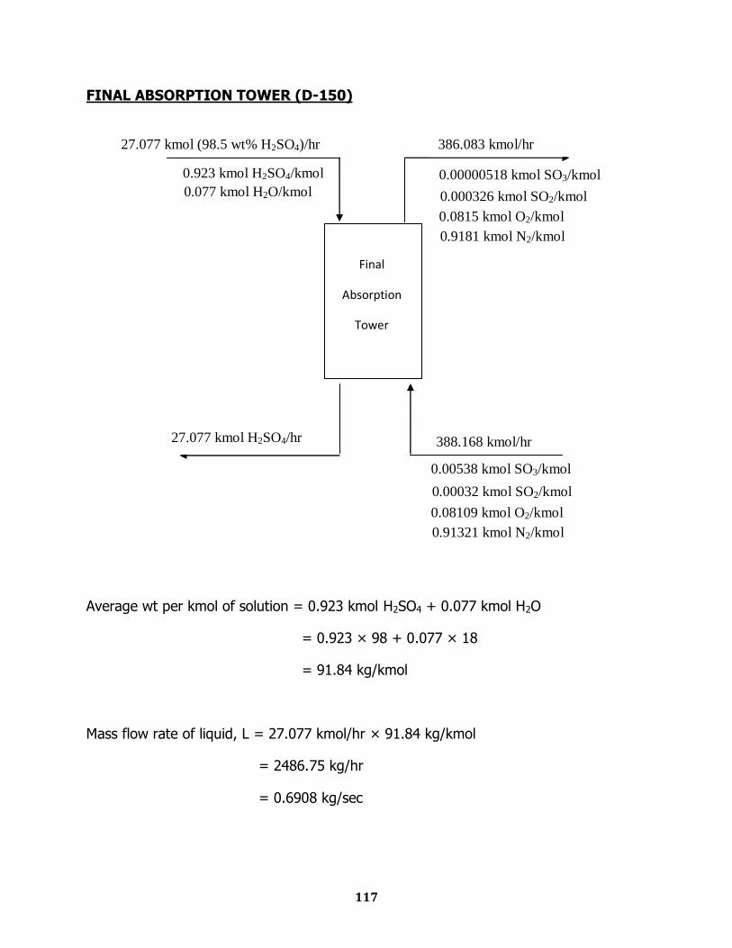
FINAL ABSORPTION TOWER (D-150)
Average wt per kmol of solution = 0.923 kmol H2SO4 + 0.077 kmol H2O
= 0.923 × 98 + 0.077 × 18
= 91.84 kg/kmol
Mass flow rate of liquid, L = 27.077 kmol/hr × 91.84 kg/kmol
= 2486.75 kg/hr
= 0.6908 kg/sec
Final
Absorption
Tower
0.923 kmol H2SO4/kmol
0.077 kmol H2O/kmol
0.00538 kmol SO3/kmol
0.00032 kmol SO2/kmol
0.08109 kmol O2/kmol
0.91321 kmol N2/kmol
27.077 kmol (98.5 wt% H2SO4)/hr
27.077 kmol H2SO4/hr
388.168 kmol/hr
0.00000518 kmol SO3/kmol
0.000326 kmol SO2/kmol
0.0815 kmol O2/kmol
0.9181 kmol N2/kmol
386.083 kmol/hr

118
Mass flow rate of gas, G = 388.168 kmol/hr × [0.09697×64 + 0.00538×80 +
0.08109×32 + 0.91321×28]
= 13508.728 kg/hr
= 3.7524 kg/sec
Specific Gravity of a 98.5wt % H2SO4 = 1.825 [from „Sulfuric Acid Manufacturing‟ by
Devenport]
Density, ρL = 1.825 × 1000 kg/m3
= 1825 kg/m3
Weight of gas per kmol, M = [0.09697×64 + 0.00538×80 + 0.08109×32 +
0.91321×28]
= 34.8012 kg/kmol
ρg =
= 0.8836 kg/m3
μL = 5.2 cP [from Devenport]
Packing Material:
1.5 inch Ceramic Intalox Saddles
From McCabe Smith,
Bulk density = 39 lb/ft3
Total area = 59 ft2/ft3
Porosity = 0.76
119
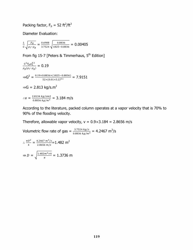
Packing factor, Fp = 52 ft2/ft3
Diameter Evaluation:
=
= 0.00405
From fig 15-7 [Peters & Timmerhaus, 5th Edition]
= 0.19
G2 =
= 7.9151
G = 2.813 kg/s.m2
v =
= 3.184 m/s
According to the literature, packed column operates at a vapor velocity that is 70% to
90% of the flooding velocity.
Therefore, allowable vapor velocity, v = 0.9 3.184 = 2.8656 m/s
Volumetric flow rate of gas =
= 4.2467 m3/s
=
=1.482 m2
=
= 1.3736 m
120
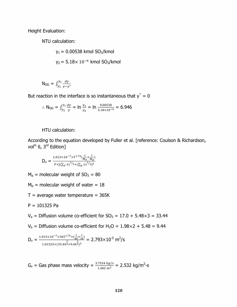
Height Evaluation:
NTU calculation:
y1 = 0.00538 kmol SO3/kmol
y2 = 5.18 kmol SO3/kmol
NOG =
But reaction in the interface is so instantaneous that y* = 0
NOG =
= ln
= ln
= 6.946
HTU calculation:
According to the equation developed by Fuller et al. [reference: Coulson & Richardson,
volm 6, 3rd Edition]
Dv =
Ma = molecular weight of SO3 = 80
Mb = molecular weight of water = 18
T = average water temperature = 365K
P = 101325 Pa
Va = Diffusion volume co-efficient for SO3 = 17.0 + 5.48 3 = 33.44
Vb = Diffusion volume co-efficient for H2O = 1.98 2 + 5.48 = 9.44
Dv =
= 2.793×10⁻⁵ m2/s
Gv = Gas phase mass velocity =
= 2.532 kg/m2-s

121
av = Packing surface area per unit volume of packing = 59 ft2/ft3 = 193.57 m2/m3
μv = 2.595 × 10⁻⁵ kg/m-s
According to the correlation of Onda et al. [Ref: Perry‟s Chemical Engineering
Handbook, pp 5-80, table 5-24],
=
Here,
C1 = 5.23
=
= 77.94
=
= 1.017
= = 0.0184
From the correlation,
=
= 5.23 77.94 1.017 0.0184 = 7.6278
kG = 7.6278 193.57
2.793 10-5
= 1.378 10-3
V =
= 0.0728
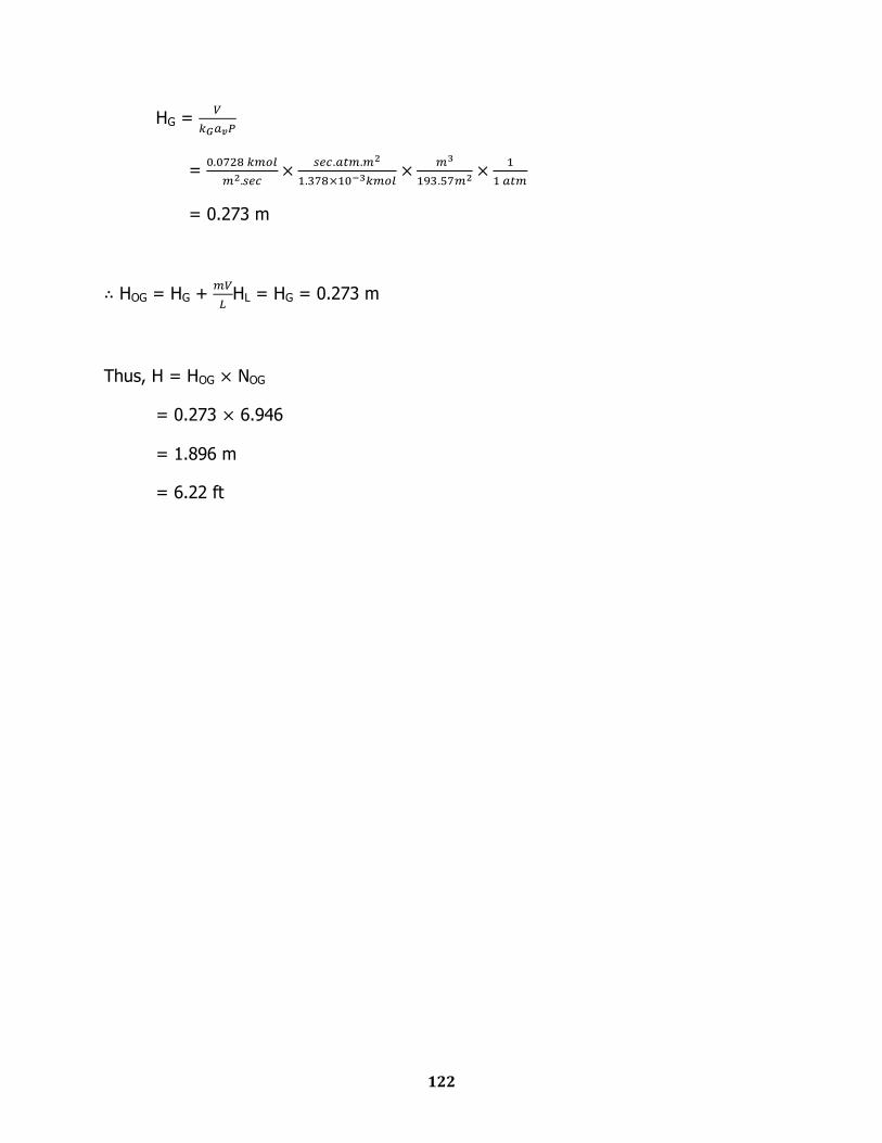
122
HG =
=
= 0.273 m
HOG = HG +
HL = HG = 0.273 m
Thus, H = HOG NOG
= 0.273 6.946
= 1.896 m
= 6.22 ft
123
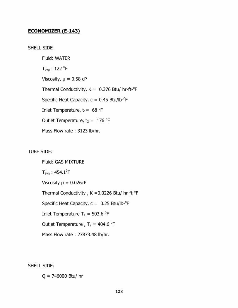
ECONOMIZER (E-143)
SHELL SIDE :
Fluid: WATER
Tavg : 122 0F
Viscosity, μ = 0.58 cP
Thermal Conductivity, K = 0.376 Btu/ hr-ft-oF
Specific Heat Capacity, c = 0.45 Btu/lb-oF
Inlet Temperature, t1= 68 oF
Outlet Temperature, t2 = 176 oF
Mass Flow rate : 3123 lb/hr.
TUBE SIDE:
Fluid: GAS MIXTURE
Tavg : 454.10F
Viscosity μ = 0.026cP
Thermal Conductivity , K =0.0226 Btu/ hr-ft-oF
Specific Heat Capacity, c = 0.25 Btu/lb-oF
Inlet Temperature T1 = 503.6 oF
Outlet Temperature , T2 = 404.6 oF
Mass Flow rate : 27873.48 lb/hr.
SHELL SIDE:
Q = 746000 Btu/ hr
124
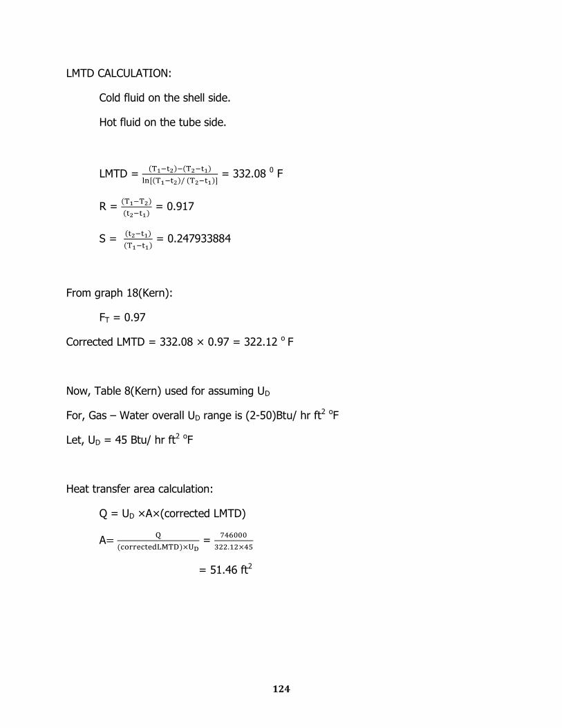
LMTD CALCULATION:
Cold fluid on the shell side.
Hot fluid on the tube side.
LMTD =
= 332.08 0 F
R =
= 0.917
S =
= 0.247933884
From graph 18(Kern):
FT = 0.97
Corrected LMTD = 332.08 × 0.97 = 322.12 o F
Now, Table 8(Kern) used for assuming UD
For, Gas – Water overall UD range is (2-50)Btu/ hr ft2 oF
Let, UD = 45 Btu/ hr ft2 oF
Heat transfer area calculation:
Q = UD ×A×(corrected LMTD)
A
=
= 51.46 ft2
125
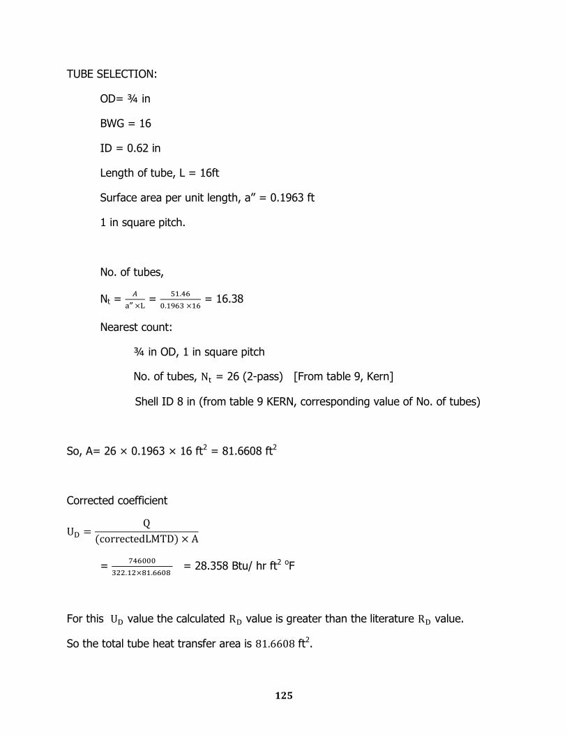
TUBE SELECTION:
OD= ¾ in
BWG = 16
ID = 0.62 in
Length of tube, L = 16ft
Surface area per unit length, a‟‟ = 0.1963 ft
1 in square pitch.
No. of tubes,
Nt =
‟‟ =
= 16.38
Nearest count:
¾ in OD, 1 in square pitch
No. of tubes, = 26 (2-pass) [From table 9, Kern]
Shell ID 8 in (from table 9 KERN, corresponding value of No. of tubes)
So, A= 26 × 0.1963 × 16 ft2 = 81.6608 ft2
Corrected coefficient
=
= 28.358 Btu/ hr ft2 oF
For this value the calculated value is greater than the literature value.
So the total tube heat transfer area is ft2.
126
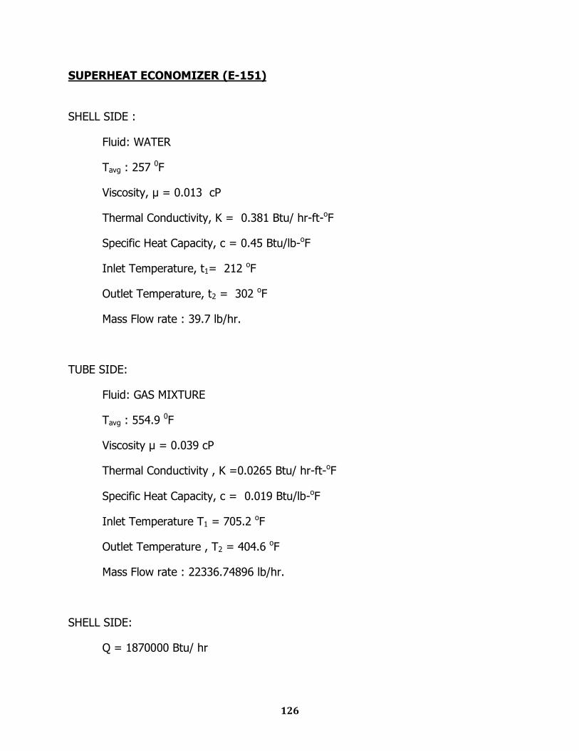
SUPERHEAT ECONOMIZER (E-151)
SHELL SIDE :
Fluid: WATER
Tavg : 257 0F
Viscosity, μ = 0.013 cP
Thermal Conductivity, K = 0.381 Btu/ hr-ft-oF
Specific Heat Capacity, c = 0.45 Btu/lb-oF
Inlet Temperature, t1= 212 oF
Outlet Temperature, t2 = 302 oF
Mass Flow rate : 39.7 lb/hr.
TUBE SIDE:
Fluid: GAS MIXTURE
Tavg : 554.9 0F
Viscosity μ = 0.039 cP
Thermal Conductivity , K =0.0265 Btu/ hr-ft-oF
Specific Heat Capacity, c = 0.019 Btu/lb-oF
Inlet Temperature T1 = 705.2 oF
Outlet Temperature , T2 = 404.6 oF
Mass Flow rate : 22336.74896 lb/hr.
SHELL SIDE:
Q = 1870000 Btu/ hr
127
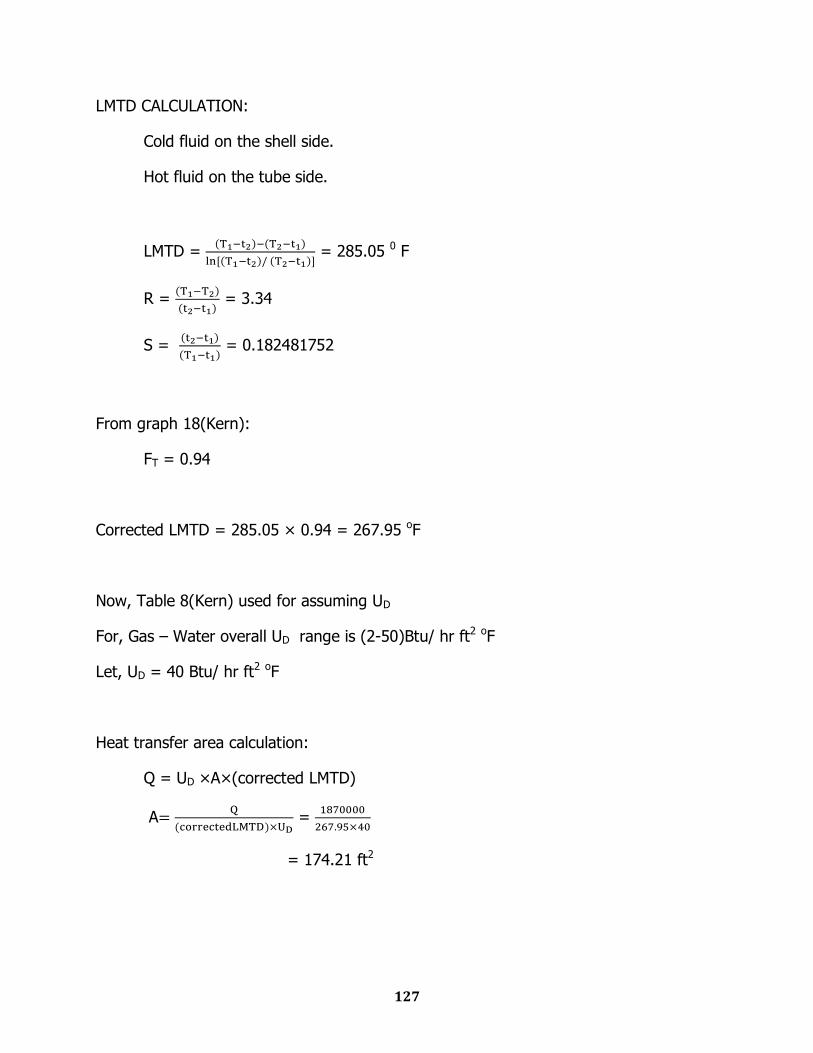
LMTD CALCULATION:
Cold fluid on the shell side.
Hot fluid on the tube side.
LMTD =
= 285.05 0 F
R =
= 3.34
S =
= 0.182481752
From graph 18(Kern):
FT = 0.94
Corrected LMTD = 285.05 × 0.94 = 267.95 oF
Now, Table 8(Kern) used for assuming UD
For, Gas – Water overall UD range is (2-50)Btu/ hr ft2 oF
Let, UD = 40 Btu/ hr ft2 oF
Heat transfer area calculation:
Q = UD ×A×(corrected LMTD)
A
=
= 174.21 ft2
128
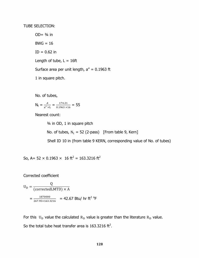
TUBE SELECTION:
OD= ¾ in
BWG = 16
ID = 0.62 in
Length of tube, L = 16ft
Surface area per unit length, a‟‟ = 0.1963 ft
1 in square pitch.
No. of tubes,
Nt =
‟‟ =
= 55
Nearest count:
¾ in OD, 1 in square pitch
No. of tubes, = 52 (2-pass) [From table 9, Kern]
Shell ID 10 in (from table 9 KERN, corresponding value of No. of tubes)
So, A= 52 × 0.1963 × 16 ft2 = 163.3216 ft2
Corrected coefficient
=
= 42.67 Btu/ hr ft2 oF
For this value the calculated value is greater than the literature value.
So the total tube heat transfer area is 163.3216 ft2.
129
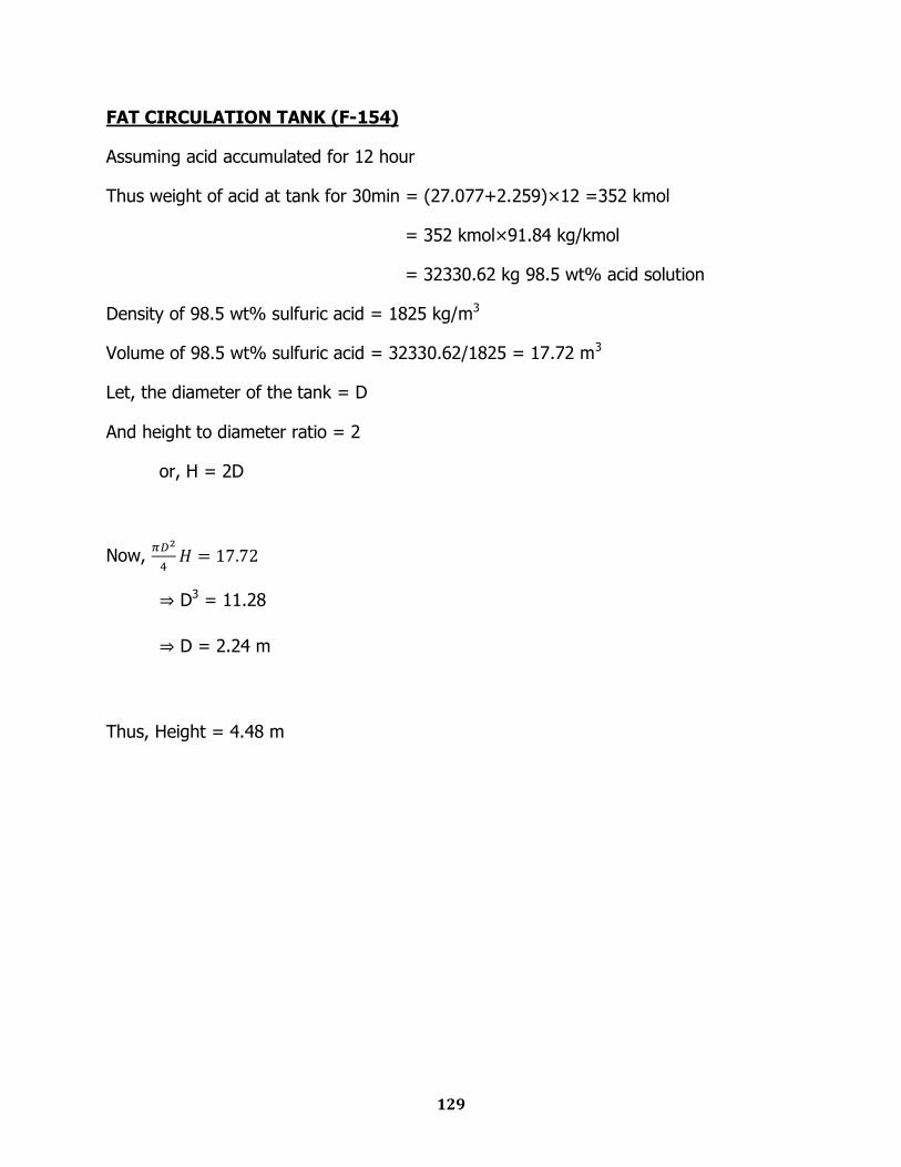
FAT CIRCULATION TANK (F-154)
Assuming acid accumulated for 12 hour
Thus weight of acid at tank for 30min = (27.077+2.259)×12 =352 kmol
= 352 kmol×91.84 kg/kmol
= 32330.62 kg 98.5 wt% acid solution
Density of 98.5 wt% sulfuric acid = 1825 kg/m3
Volume of 98.5 wt% sulfuric acid = 32330.62/1825 = 17.72 m3
Let, the diameter of the tank = D
And height to diameter ratio = 2
or, H = 2D
Now,
D3 = 11.28
D = 2.24 m
Thus, Height = 4.48 m
130
IAT & DT CIRCULATION TOWER (F-144)
Assuming acid accumulated for 30min or half an hour
Thus weight of acid at tank for 30min = (515.156+45.273+257.578)×0.5 = 409 kmol
= 409 kmol×91.84 kg/kmol
= 37562.56 kg 98.5 wt% acid solution
Density of 98.5 wt% sulfuric acid = 1825 kg/m3
Volume of 98.5 wt% sulfuric acid = 37562.56/1825 = 20.58 m3
Let, the diameter of the tank = D
And height to diameter ratio = 2
or, H = 2D
Now,
D3 = 13.10
D = 2.36 m
Thus, Height = 4.72 m
131
COOLER-1 (E-152)
SHELL SIDE :
Fluid: WATER
Tavg : 81.5 0F
Viscosity, μ = 0.9 cP
Thermal Conductivity, K = 0.356 Btu/ hr-ft-oF
Specific Heat Capacity, c = 1 Btu/lb-oF
Inlet Temperature, t1= 68 oF
Outlet Temperature, t2 = 95 oF
Mass Flow rate, W = 3548.384 lb/hr.
TUBE SIDE:
Fluid: GAS MIXTURE
Tavg : 194 0F
Viscosity μ = 0.013 cP
Thermal Conductivity , K =0.0183 Btu/ hr-ft-oF
Specific Heat Capacity, c = 0.24 Btu/lb-oF
Inlet Temperature T1 = 217.4 oF
Outlet Temperature , T2 = 170.6 oF
Mass Flow rate : 5049.798296 lb/hr.
SHELL SIDE:
Q = 96100 Btu/ hr
132
LMTD CALCULATION:
Cold fluid on the shell side.
Hot fluid on the tube side.
LMTD =
= 112.21 0 F
R =
= 1.733
S =
= 0.181
From graph 18(Kern):
FT = 0.94
Corrected LMTD = 112.21 × 0.94 =105.48 o F
Now, Table 8(Kern) used for assuming UD
For, Gas – Water overall UD range is (2-50)Btu/ hr ft2 oF
Let, UD = 45 Btu/ hr ft2 oF
Heat transfer area calculation:
Q = UD ×A×(corrected LMTD)
A
=
= 20.25 ft2
133
TUBE SELECTION:
OD= ¾ in
BWG = 16
ID = 0.62 in
Length of tube, L = 8 ft
Surface area per unit length, a‟‟ = 0.1963 ft
1 in square pitch.
No. of tubes,
Nt =
‟‟ =
= 13
Nearest count:
¾ in OD, 1 in square pitch
No. of tubes, = 26 (2-pass) [From table 9, Kern]
Shell ID 8 in (from table 9 KERN, corresponding value of No. of tubes)
So, A= 26 × 0.1963 × 8 ft2 = 40.8304 ft2
Corrected coefficient
=
= 22.32 Btu/ hr ft2 oF
For this value the calculated value is greater than the literature value.
So the total tube heat transfer area is 40.8304 ft2.
134
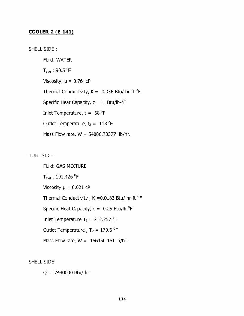
COOLER-2 (E-141)
SHELL SIDE :
Fluid: WATER
Tavg : 90.5 0F
Viscosity, μ = 0.76 cP
Thermal Conductivity, K = 0.356 Btu/ hr-ft-oF
Specific Heat Capacity, c = 1 Btu/lb-oF
Inlet Temperature, t1= 68 oF
Outlet Temperature, t2 = 113 oF
Mass Flow rate, W = 54086.73377 lb/hr.
TUBE SIDE:
Fluid: GAS MIXTURE
Tavg : 191.426 0F
Viscosity μ = 0.021 cP
Thermal Conductivity , K =0.0183 Btu/ hr-ft-oF
Specific Heat Capacity, c = 0.25 Btu/lb-oF
Inlet Temperature T1 = 212.252 oF
Outlet Temperature , T2 = 170.6 oF
Mass Flow rate, W = 156450.161 lb/hr.
SHELL SIDE:
Q = 2440000 Btu/ hr
135
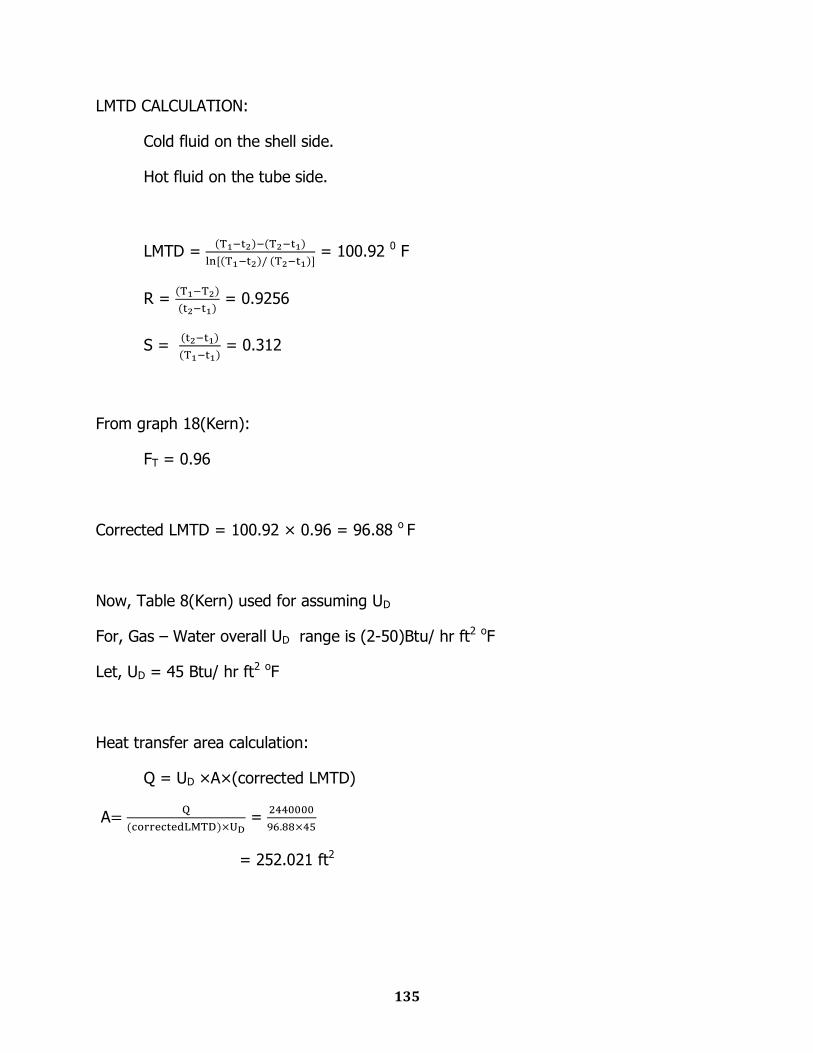
LMTD CALCULATION:
Cold fluid on the shell side.
Hot fluid on the tube side.
LMTD =
= 100.92 0 F
R =
= 0.9256
S =
= 0.312
From graph 18(Kern):
FT = 0.96
Corrected LMTD = 100.92 × 0.96 = 96.88 o F
Now, Table 8(Kern) used for assuming UD
For, Gas – Water overall UD range is (2-50)Btu/ hr ft2 oF
Let, UD = 45 Btu/ hr ft2 oF
Heat transfer area calculation:
Q = UD ×A×(corrected LMTD)
A
=
= 252.021 ft2
136
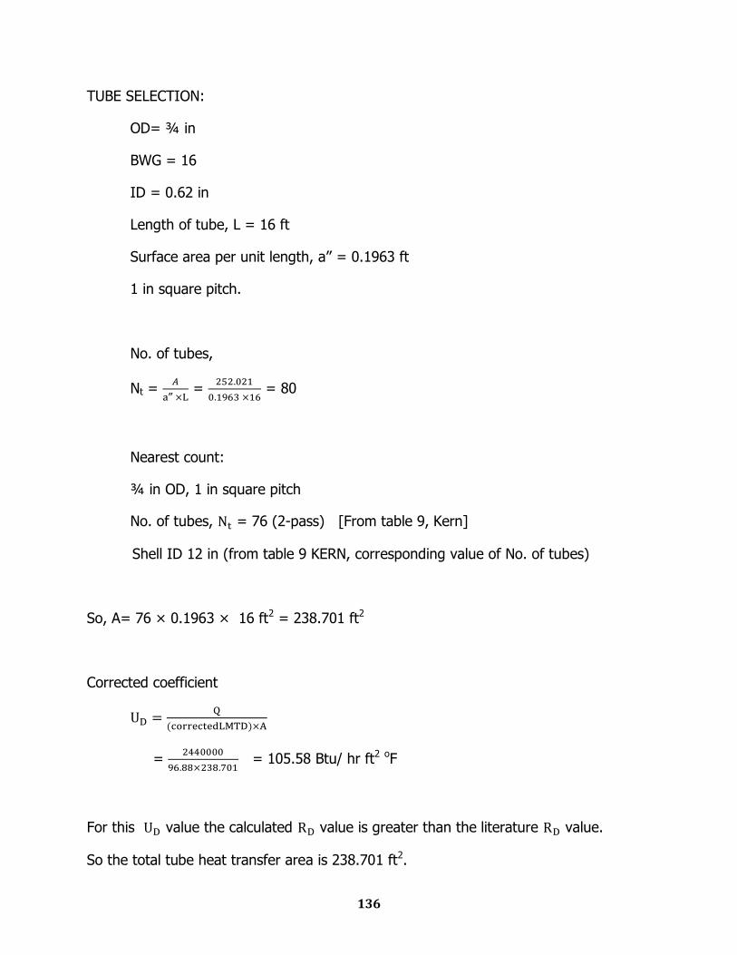
TUBE SELECTION:
OD= ¾ in
BWG = 16
ID = 0.62 in
Length of tube, L = 16 ft
Surface area per unit length, a‟‟ = 0.1963 ft
1 in square pitch.
No. of tubes,
Nt =
‟‟ =
= 80
Nearest count:
¾ in OD, 1 in square pitch
No. of tubes, = 76 (2-pass) [From table 9, Kern]
Shell ID 12 in (from table 9 KERN, corresponding value of No. of tubes)
So, A= 76 × 0.1963 × 16 ft2 = 238.701 ft2
Corrected coefficient
=
= 105.58 Btu/ hr ft2 oF
For this value the calculated value is greater than the literature value.
So the total tube heat transfer area is 238.701 ft2.

137
COOLER-3 (E-162)
SHELL SIDE:
Fluid: WATER
Tavg : 95 0F
Viscosity, μ = 0.76 cP
Thermal Conductivity, K = 0.356 Btu/ hr-ft-oF
Specific Heat Capacity, c = 1 Btu/lb-oF
Inlet Temperature, t1= 68 oF
Outlet Temperature, t2 = 122 oF
Mass Flow rate, W = 7775.66 lb/hr.
TUBE SIDE:
Fluid: GAS MIXTURE
Tavg : 150.926 0F
Viscosity μ = 0.013 cP
Thermal Conductivity , K =0.0183 Btu/ hr-ft-oF
Specific Heat Capacity, c = 0.24 Btu/lb-oF
Inlet Temperature T1 = 212.252 oF
Outlet Temperature , T2 = 89.6 oF
Mass Flow rate, W = 9167.34988 lb/hr.
SHELL SIDE:
Q = 421000 Btu/ hr
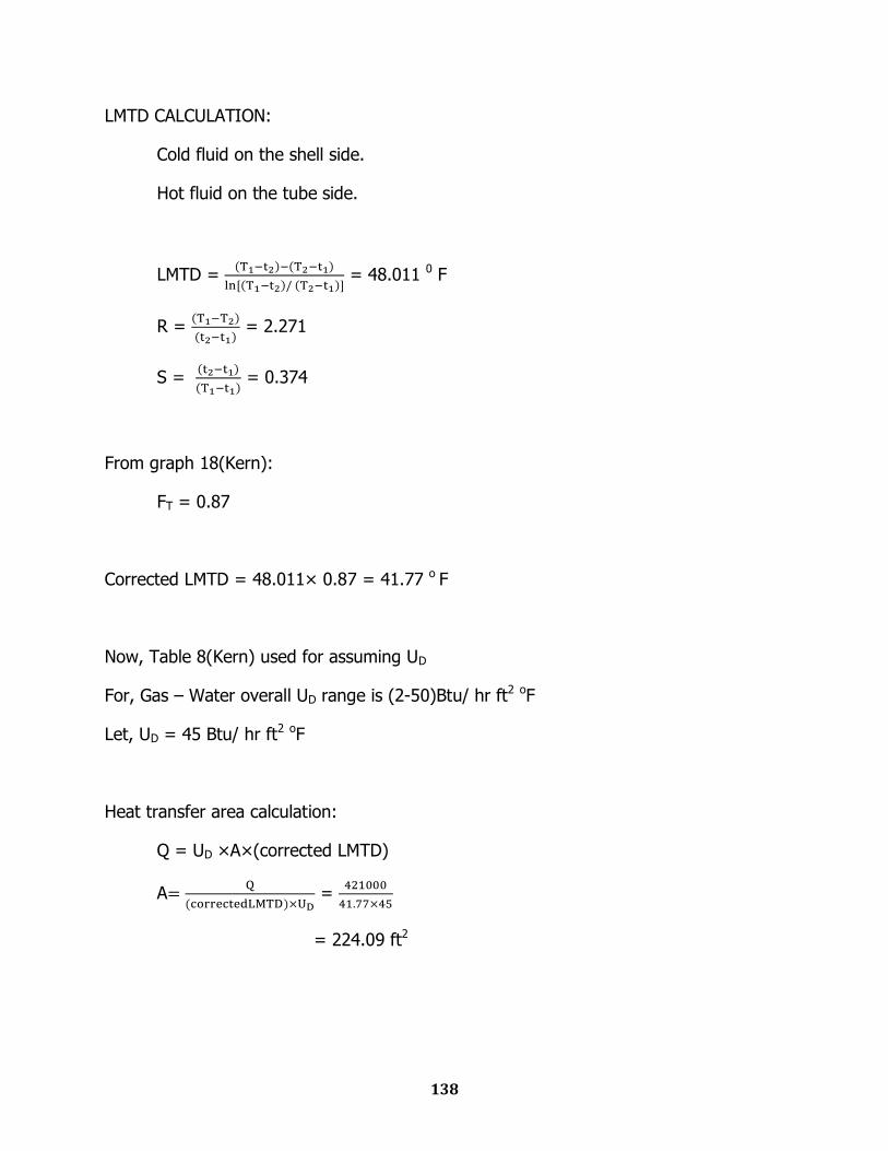
138
LMTD CALCULATION:
Cold fluid on the shell side.
Hot fluid on the tube side.
LMTD =
= 48.011 0 F
R =
= 2.271
S =
= 0.374
From graph 18(Kern):
FT = 0.87
Corrected LMTD = 48.011× 0.87 = 41.77 o F
Now, Table 8(Kern) used for assuming UD
For, Gas – Water overall UD range is (2-50)Btu/ hr ft2 oF
Let, UD = 45 Btu/ hr ft2 oF
Heat transfer area calculation:
Q = UD ×A×(corrected LMTD)
A
=
= 224.09 ft2
139
TUBE SELECTION:
OD= ¾ in
BWG = 16
ID = 0.62 in
Length of tube, L = 16 ft
Surface area per unit length, a‟‟ = 0.1963 ft
1 in square pitch.
No. of tubes,
Nt =
‟‟ =
= 71
Nearest count:
¾ in OD, 1 in square pitch
No. of tubes, = 76 (2-pass) [From table 9, Kern]
Shell ID 12 in (from table 9 KERN, corresponding value of No. of tubes)
So, A= 76 × 0.1963 × 16 ft2 = 238.701 ft2
Corrected coefficient
=
= 42.24562344 Btu/ hr ft2 oF
For this value the calculated value is greater than the literature value.
So the total tube heat transfer area is 238.701 ft2.
140
STORAGE TANK (F-160)
Amount of Sulfuric acid in 6 days =100x6x1000
=600000 Kg
Density of acid = 1825 Kg/m3
Volume of the acid = 328.767 m3
Capacity =328.77 m3
Type: Closed cylindrical pressure vessel
Assuming length-diameter ratio = 1.55
Length = 10 m
Diameter = 6.47 m
Chapter Thirteen
Detailed Engineering Design
Converter
Interpass Absorption Column
Waste Heat Boiler-2
Storage Tank
13.1
Converter Design
Equipment Sizing
Mechanical Design
Engineering Drawing
P & ID Diagram
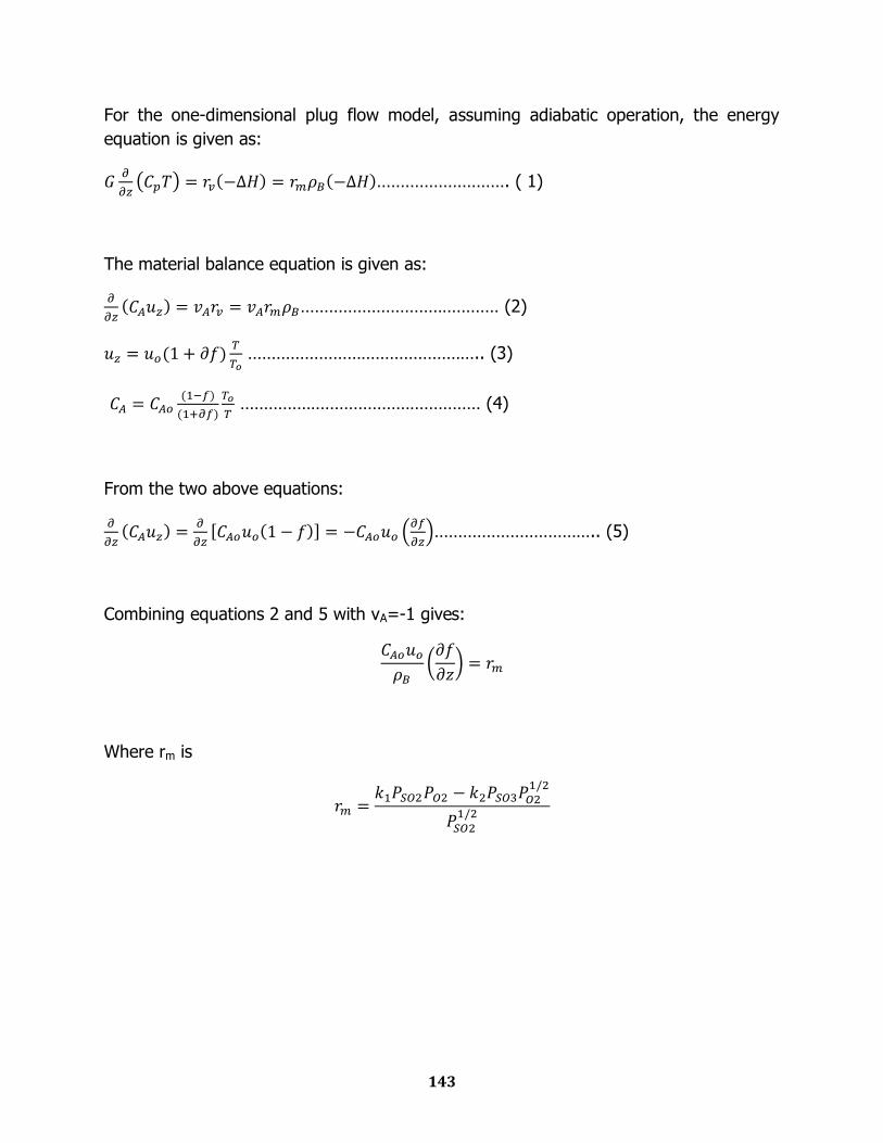
143
For the one-dimensional plug flow model, assuming adiabatic operation, the energy
equation is given as:
………………………. ( 1)
The material balance equation is given as:
…………………………………… (2)
………………………………………….. (3)
…………………………………………… (4)
From the two above equations:
…………………………….. (5)
Combining equations 2 and 5 with vA=-1 gives:
Where rm is
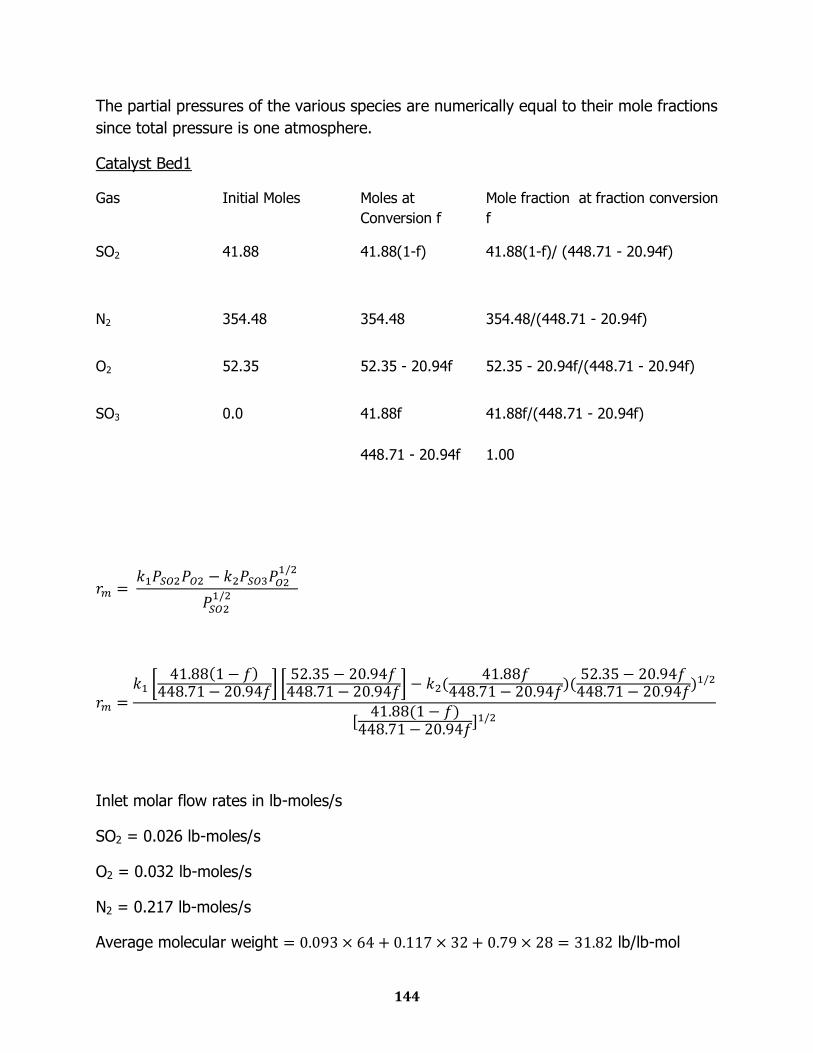
144
The partial pressures of the various species are numerically equal to their mole fractions
since total pressure is one atmosphere.
Catalyst Bed1
Gas Initial Moles Moles at
Conversion f
Mole fraction at fraction conversion
f
SO2 41.88 41.88(1-f)
41.88(1-f)/ (448.71 - 20.94f)
N2 354.48 354.48 354.48/(448.71 - 20.94f)
O2 52.35 52.35 - 20.94f 52.35 - 20.94f/(448.71 - 20.94f)
SO3 0.0 41.88f 41.88f/(448.71 - 20.94f)
448.71 - 20.94f 1.00
Inlet molar flow rates in lb-moles/s
SO2 = 0.026 lb-moles/s
O2 = 0.032 lb-moles/s
N2 = 0.217 lb-moles/s
Average molecular weight lb/lb-mol
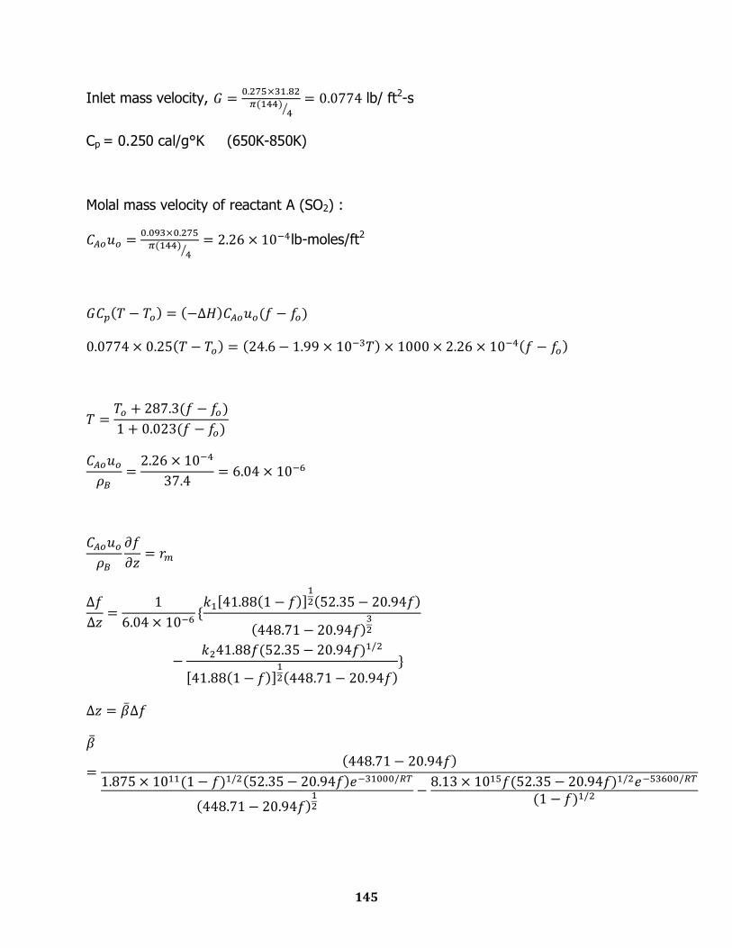
145
Inlet mass velocity,
lb/ ft2-s
Cp = 0.250 cal/g°K (650K-850K)
Molal mass velocity of reactant A (SO2) :
lb-moles/ft2
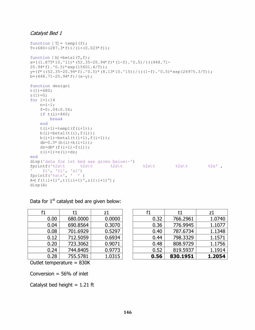
146
Catalyst Bed 1
function [T]= temp1(f); T=(680+(287.3*f))/(1+(0.023*f));
function [b]=beta1(T,f); x=((1.875*10.^11)*(52.35-20.94*f)*(1-f).^0.5)/(((448.71-
20.94*f).^0.5)*exp(15601.4/T)); y=(f*((52.35-20.94*f).^0.5)*(8.13*10.^15))/(((1-f).^0.5)*exp(26975.3/T)); b=(448.71-20.94*f)/(x-y);
function design1 t(1)=680; z(1)=0; for i=1:14 n=i-1; f=0:.04:0.56; if t(i)>860; break end t(i+1)=temp1(f(i+1)); b(i)=beta1(t(i),f(i)); b(i+1)=beta1(t(i+1),f(i+1)); db=0.5*(b(i)+b(i+1)); dz=db*(f(i+1)-f(i)); z(i+1)=z(i)+dz; end disp('data for 1st bed are given below:-') fprintf('%2s\t %2s\t %2s\t %2s\t %2s\t %2s' ,
' f1', 't1', 'z1') fprintf('%s\n', ' ' ) A=[f(1:i+1)',t(1:i+1)',z(1:i+1)']; disp(A)
Data for 1st catalyst bed are given below:
f1 t1 z1
0.00 680.0000 0.0000
0.04 690.8564 0.3070
0.08 701.6929 0.5297
0.12 712.5059 0.6934
0.20 723.3062 0.9071
0.24 744.8405 0.9773
0.28 755.5781 1.0315
f1 t1 z1
0.32 766.2961 1.0740
0.36 776.9945 1.1077
0.40 787.6734 1.1348
0.44 798.3329 1.1571
0.48 808.9729 1.1756
0.52 819.5937 1.1914
0.56 830.1951 1.2054
Outlet temperature = 830K
Conversion = 56% of inlet
Catalyst bed height = 1.21 ft

147
Catalyst Bed 2
Gas Initial Moles Moles at Conversion f
Mole fraction at fraction conversion f
SO2 18.43 18.43(1-f)
18.43(1-f)/ (436.99 – 9.215f)
N2 354.48 354.48 354.48/(436.99 – 9.215f)
O2 40.63 40.63 – 9.215f (40.63 –9.215f)/(436.99 – 9.215f)
SO3 23.45 23.45 +18.43f (23.45+18.43f)/(436.99 – 9.215f)
436.99 – 9.215f 1.00
Inlet molar flow rates in lb-moles/s
SO2 = 0.0112 lb-moles/s
O2 = 0.025 lb-moles/s
N2 = 0.217 lb-moles/s
SO3 = 0.0144 lb-moles/s
Average molecular weight
Inlet mass velocity,
lb/ ft2-s
Cp = 0.250 cal/g°K (650K-850K)
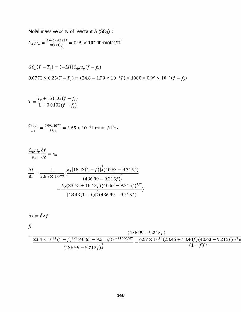
148
Molal mass velocity of reactant A (SO2) :
lb-moles/ft2
lb-mols/ft2-s

149
Catalyst Bed 2
function[T]=temp2(f) T=(690+(126.02*(f-0)))/(1+(0.0102*(f-0)));
function [b]=beta2(T,f); x=((2.84*10.^11)*(40.63-9.215*f)*(1-f).^0.5)/(((436.99-
9.215*f).^0.5)*exp(15601.4/T)); y=((23.45+18.43*f)*((40.63-9.215*f).^0.5)*(6.67*10.^14))/(((1-
f).^0.5)*exp(26975.3/T)); b=(436.99-9.215*f)/(x-y);
function design2 T(1)= 690; Z(1)= 0; for i=1:10 f=0:0.07:0.70; if T(i)>850; break end T(i+1)=temp2(f(i+1)); b(i)= beta2(T(i),f(i)); b(i+1)=beta2(T(i+1),f(i+1)); db=0.5*(b(i)+b(i+1)); dz=db*(f(i+1)-f(i)); Z(i+1)= Z(i)+dz; end disp('data for 2nd bed are given below:-') fprintf('%2s\t %2s\t %2s\t %2s\t %2s\t %2s' ,
' f1', 't1', 'z1') fprintf('%s\n', ' ' ) A=[f(1:i+1)',T(1:i+1)',Z(1:i+1)']; disp(A)
Data for 2nd catalyst bed are given below:
f1 t1 z1
0.00 690.0000 0.0000
0.07 698.3228 0.3348
0.14 706.6337 0.6064
0.21 714.9328 0.8294
0.28 723.2201 1.0151
0.35 731.4956 1.1721
f1 t1 z1
0.42 739.7593 1.3074
0.49 748.0112 1.4268
0.56 756.2515 1.5357
0.63 764.4801 1.6404
0.70 772.6969 1.7509
Outlet temperature = 772 K
Conversion = 70% of inlet
Catalyst bed height = 1.75 ft
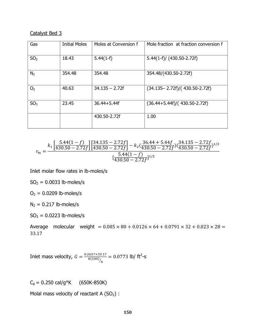
150
Catalyst Bed 3
Gas Initial Moles Moles at Conversion f Mole fraction at fraction conversion f
SO2 18.43 5.44(1-f)
5.44(1-f)/ (430.50-2.72f)
N2 354.48 354.48 354.48/(430.50-2.72f)
O2 40.63 34.135 – 2.72f (34.135– 2.72f)/( 430.50-2.72f)
SO3 23.45 36.44+5.44f (36.44+5.44f)/( 430.50-2.72f)
430.50-2.72f 1.00
Inlet molar flow rates in lb-moles/s
SO2 = 0.0033 lb-moles/s
O2 = 0.0209 lb-moles/s
N2 = 0.217 lb-moles/s
SO3 = 0.0223 lb-moles/s
Average molecular weight
Inlet mass velocity,
lb/ ft2-s
Cp = 0.250 cal/g°K (650K-850K)
Molal mass velocity of reactant A (SO2) :
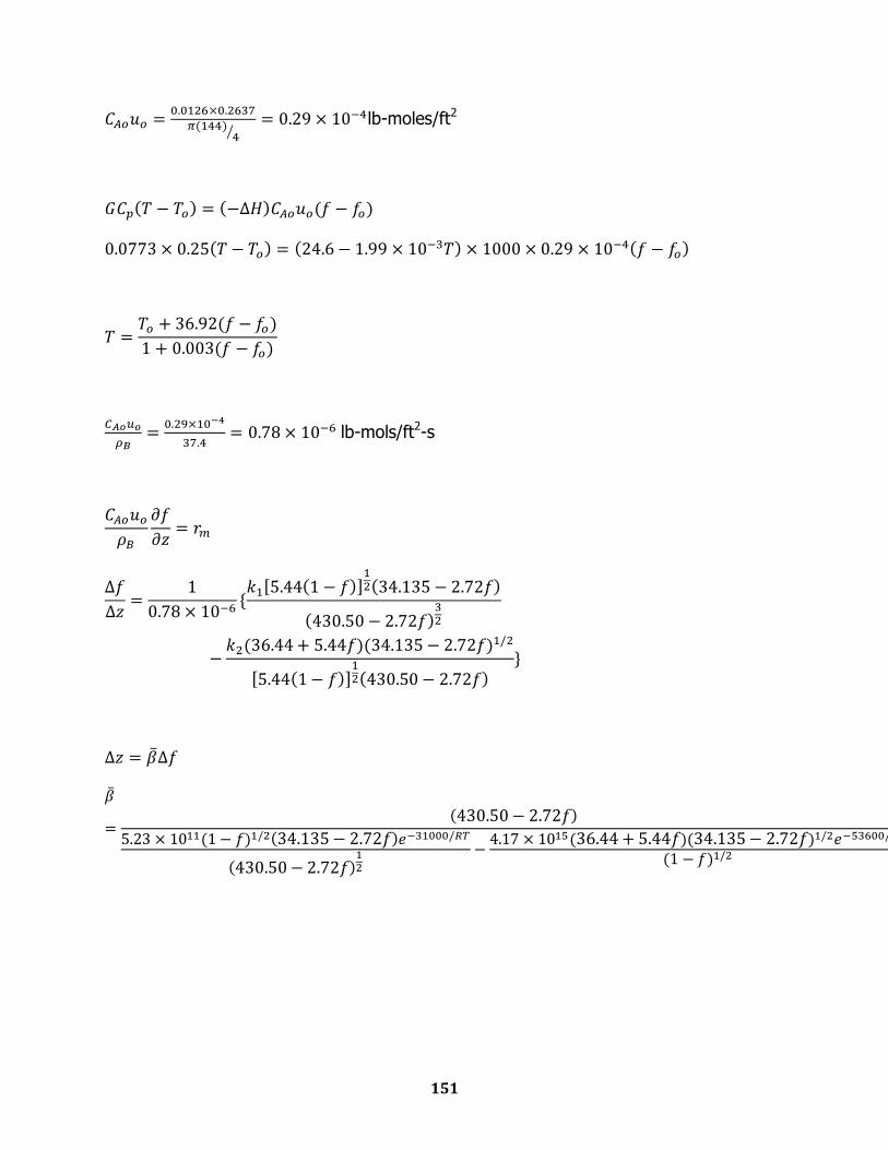
151
lb-moles/ft2
lb-mols/ft2-s

152
Catalyst Bed 3
function [T]= temp3(f) T=(658+(36.92*(f-0)))/(1+(0.003*(f-0)));
function [b]=beta3(T,f); x=((5.23*10.^11)*(34.135-2.72*f)*(1-f).^0.5)/(((430.5-
2.72*f).^0.5)*exp(15601.4/T)); y=((36.44+5.44*f)*((34.135-2.72*f).^0.5)*(4.17*10.^15))/(((1-
f).^0.5)*exp(26975.3/T)); b=(430.5-2.72*f)/(x-y);
function design3 T(1)= 658; Z(1)= 0; for i=1:31 f=0:0.03:0.93; if T(i)>860; break end T(i+1)=temp3(f(i+1)); b(i)= beta3(T(i),f(i)); b(i+1)=beta3(T(i+1),f(i+1)); db=0.5*(b(i)+b(i+1)); dz=db*(f(i+1)-f(i)); Z(i+1)= Z(i)+dz; end disp('data for 3rd bed are given below:-') fprintf('%2s\t %2s\t %2s\t %2s\t %2s\t %2s' ,
' f1', 't1', 'z1') fprintf('%s\n', ' ' ) A=[f(1:i+1)',T(1:i+1)',Z(1:i+1)']; disp(A)
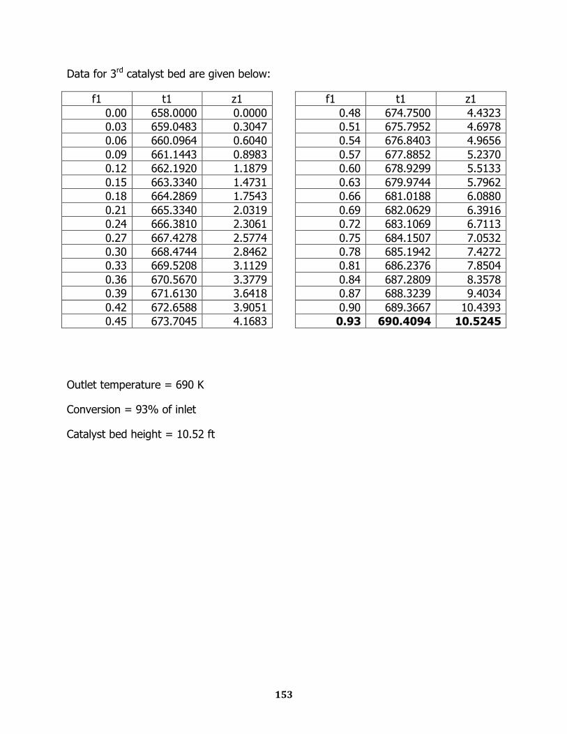
153
Data for 3rd catalyst bed are given below:
f1 t1 z1
0.00 658.0000 0.0000
0.03 659.0483 0.3047
0.06 660.0964 0.6040
0.09 661.1443 0.8983
0.12 662.1920 1.1879
0.15 663.3340 1.4731
0.18 664.2869 1.7543
0.21 665.3340 2.0319
0.24 666.3810 2.3061
0.27 667.4278 2.5774
0.30 668.4744 2.8462
0.33 669.5208 3.1129
0.36 670.5670 3.3779
0.39 671.6130 3.6418
0.42 672.6588 3.9051
0.45 673.7045 4.1683
f1 t1 z1
0.48 674.7500 4.4323
0.51 675.7952 4.6978
0.54 676.8403 4.9656
0.57 677.8852 5.2370
0.60 678.9299 5.5133
0.63 679.9744 5.7962
0.66 681.0188 6.0880
0.69 682.0629 6.3916
0.72 683.1069 6.7113
0.75 684.1507 7.0532
0.78 685.1942 7.4272
0.81 686.2376 7.8504
0.84 687.2809 8.3578
0.87 688.3239 9.4034
0.90 689.3667 10.4393
0.93 690.4094 10.5245
Outlet temperature = 690 K
Conversion = 93% of inlet
Catalyst bed height = 10.52 ft
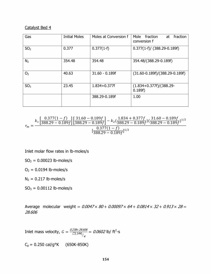
154
Catalyst Bed 4
Gas Initial Moles Moles at Conversion f Mole fraction at fraction conversion f
SO2 0.377 0.377(1-f)
0.377(1-f)/ (388.29-0.189f)
N2 354.48 354.48 354.48/(388.29-0.189f)
O2 40.63 31.60 - 0.189f (31.60-0.189f)/(388.29-0.189f)
SO3 23.45 1.834+0.377f (1.834+0.377f)/(388.29-0.189f)
388.29-0.189f 1.00
Inlet molar flow rates in lb-moles/s
SO2 = 0.00023 lb-moles/s
O2 = 0.0194 lb-moles/s
N2 = 0.217 lb-moles/s
SO3 = 0.00112 lb-moles/s
Average molecular weight 0 0047 80 0 00097 64 0 0814 32 0 913 28
28 606
Inlet mass velocity, 0 238 28 606
144 4
0 0602 lb/ ft2-s
Cp = 0.250 cal/g°K (650K-850K)
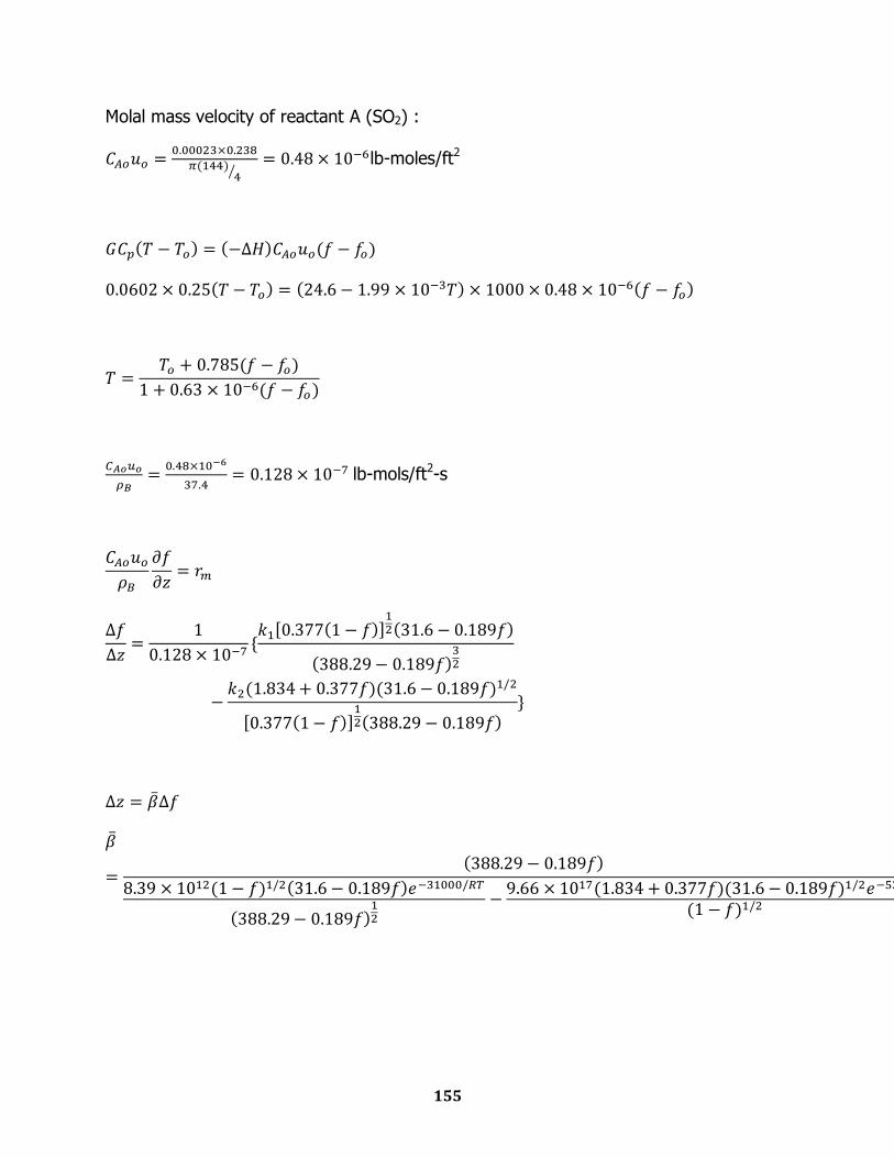
155
Molal mass velocity of reactant A (SO2) :
lb-moles/ft2
lb-mols/ft2-s

156
Catalyst Bed 4
function [T]=temp4(f) T=(640+(0.785*(f-0)))/(1+((0.63*10.^-6)*(f-0)));
function [b]=beta4(T,f); x=((8.39*10.^12)*(31.6-0.189*f)*(1-f).^0.5)/(((388.29-
0.189*f).^0.5)*exp(15601.4/T)); y=((1.834+0.377*f)*((31.6-0.189*f).^0.5)*(9.66*10.^17))/(((1-
f).^0.5)*exp(26975.3/T)); b=(388.29-0.189*f)/(x-y);
function design4 T(1)=640; Z(1)=0; for i=1:11 f=0:0.06:0.66; if T(i)>850; break end T(i+1)=temp4(f(i+1)); b(i)= beta4(T(i),f(i)); b(i+1)=beta4(T(i+1),f(i+1)); db=0.5*(b(i)+b(i+1)); dz=db*(f(i+1)-f(i)); Z(i+1)= Z(i)+dz; end disp('data for 4th bed are given below:-') fprintf('%2s\t %2s\t %2s\t %2s\t %2s\t %2s' ,
' f1', 't1', 'z1') fprintf('%s\n', ' ' ) A=[f(1:i+1)',T(1:i+1)',Z(1:i+1)']; disp(A)
Data for 4th catalyst bed are given below:
f1 t1 z1
0.00 640.0000 0.0000
0.06 640.0471 0.0689
0.12 640.0942 0.1400
0.18 640.1412 0.2136
0.24 640.1883 0.2899
0.30 640.2354 0.3694
f1 t1 z1
0.36 640.2825 0.4524
0.42 640.3295 0.5395
0.48 640.3766 0.6314
0.54 640.4237 0.7291
0.60 640.4708 0.8338
0.66 640.5178 0.9473
Outlet temperature = 640.5 K
Conversion = 66% of inlet
Catalyst bed height = 0.95 ft

157
Total height of catalyst packing = 14.422ft
Weight of catalyst
Daisy ring catalyst diameter = 20 mm = 0.78 in
Reynolds number, Re
Ergun equation:
Inlet gas density,
lb/ft3
From Ergun equation,
lbm/ft-s2=0.110 psi
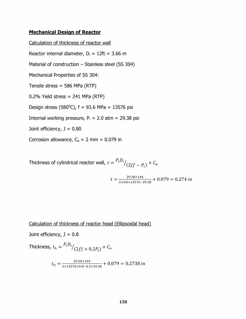
158
Mechanical Design of Reactor
Calculation of thickness of reactor wall
Reactor internal diameter, Di = 12ft = 3.66 m
Material of construction – Stainless steel (SS 304)
Mechanical Properties of SS 304:
Tensile stress = 586 MPa (RTP)
0.2% Yield stress = 241 MPa (RTP)
Design stress (580oC), f = 93.6 MPa = 13576 psi
Internal working pressure, Pi = 2.0 atm = 29.38 psi
Joint efficiency, J = 0.80
Corrosion allowance, Ca = 2 mm = 0.079 in
Thickness of cylindrical reactor wall,
Calculation of thickness of reactor head (Ellipsoidal head)
Joint efficiency, J = 0.8
Thickness,
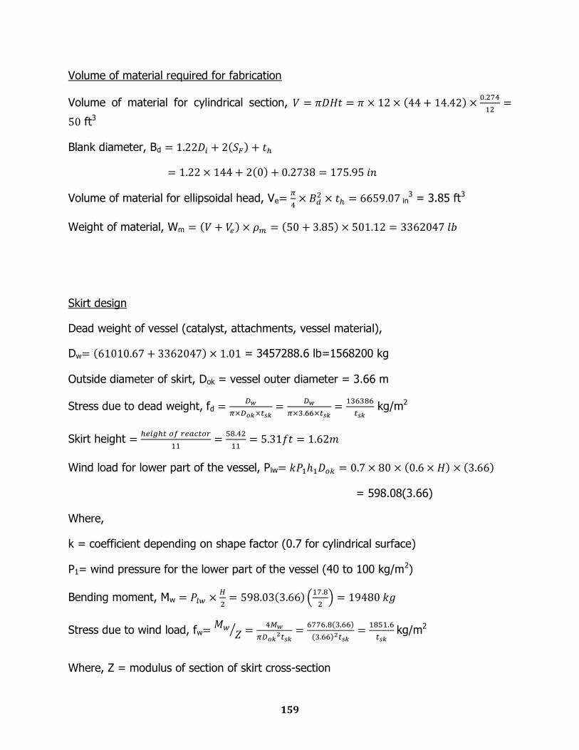
159
Volume of material required for fabrication
Volume of material for cylindrical section,
ft3
Blank diameter, Bd
Volume of material for ellipsoidal head, Ve
in3 = 3.85 ft3
Weight of material, Wm
Skirt design
Dead weight of vessel (catalyst, attachments, vessel material),
Dw = 3457288.6 lb=1568200 kg
Outside diameter of skirt, Dok = vessel outer diameter = 3.66 m
Stress due to dead weight, fd
kg/m2
Skirt height
Wind load for lower part of the vessel, Plw
= 598.08(3.66)
Where,
k = coefficient depending on shape factor (0.7 for cylindrical surface)
P1= wind pressure for the lower part of the vessel (40 to 100 kg/m2)
Bending moment, Mw
Stress due to wind load, fw
kg/m2
Where, Z = modulus of section of skirt cross-section
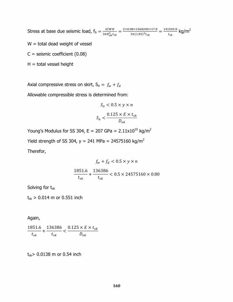
160
Stress at base due seismic load, fb
kg/m2
W = total dead weight of vessel
C = seismic coefficient (0.08)
H = total vessel height
Axial compressive stress on skirt, Sa
Allowable compressible stress is determined from:
Young‟s Modulus for SS 304, E = 207 GPa = 2.11x10¹⁰ kg/m2
Yield strength of SS 304, y = 241 MPa = 24575160 kg/m2
Therefor,
Solving for tsk
tsk > 0.014 m or 0.551 inch
Again,
tsk> 0.0138 m or 0.54 inch
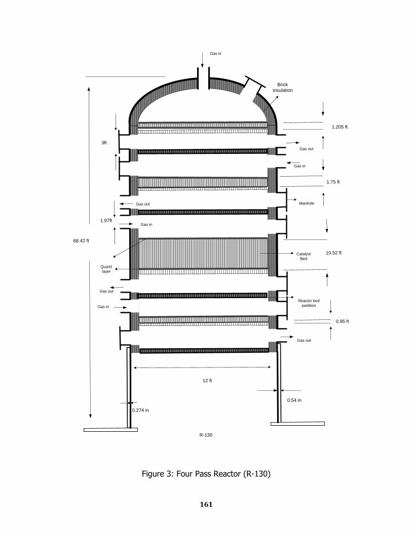
161
12 ft
3ft
1.97ft
R-130
1.205 ft
1.75 ft
10.52 ft
0.95 ft
0.274 in
0.54 in
68.42 ft
Catalyst
Bed
Manhole
Reactor bed
partition
Brick
insulation
Quartz
layer
Gas in
Gas in
Gas in
Gas in
Gas out
Gas out
Gas out
Gas out
Figure 3: Four Pass Reactor (R-130)
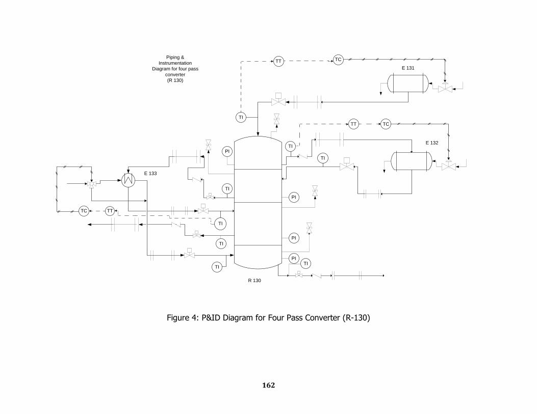
162
TI
TI
TI
TI
TC
TC
TI
TI
TI
PI
PI
PI
TI
TC
E 131
E 132
PI
Piping &
Instrumentation
Diagram for four pass
converter
(R 130)
R 130
E 133
TT
TT
TT
Figure 4: P&ID Diagram for Four Pass Converter (R-130)
13.2
Interpass Absorption Column Design
Equipment Sizing
Mechanical Design
Engineering Drawing
P & ID Diagram
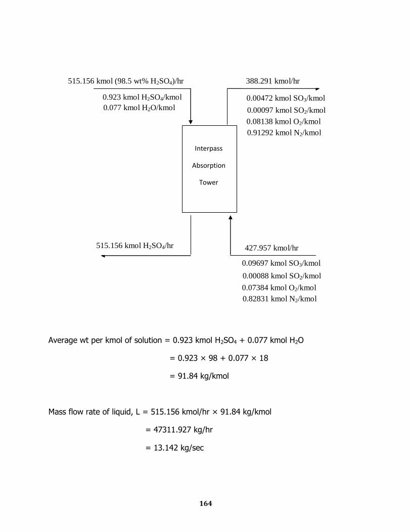
164
Average wt per kmol of solution = 0.923 kmol H2SO4 + 0.077 kmol H2O
= 0.923 × 98 + 0.077 × 18
= 91.84 kg/kmol
Mass flow rate of liquid, L = 515.156 kmol/hr × 91.84 kg/kmol
= 47311.927 kg/hr
= 13.142 kg/sec
Interpass
Absorption
Tower
0.923 kmol H2SO4/kmol
0.077 kmol H2O/kmol
0.09697 kmol SO3/kmol
0.00088 kmol SO2/kmol
0.07384 kmol O2/kmol
0.82831 kmol N2/kmol
515.156 kmol (98.5 wt% H2SO4)/hr
515.156 kmol H2SO4/hr
427.957 kmol/hr
0.00472 kmol SO3/kmol
0.00097 kmol SO2/kmol
0.08138 kmol O2/kmol
0.91292 kmol N2/kmol
388.291 kmol/hr
165
Mass flow rate of gas, G = 427.957 kmol/hr × [0.00088×64 + 0.09697×80 +
0.07384×32 + 0.82831×28]
= 14280.703 kg/hr
= 3.967 kg/sec
Specific Gravity of a 98.5wt % H2SO4 = 1.825 [from „Sulfuric Acid Manufacturing‟ by
Devenport]
Density, ρL = 1.825 × 1000 kg/m3
= 1825 kg/m3
Weight of gas per kmol, M = [0.00088×64 + 0.09697×80 + 0.07384×32 +
0.82831×28]
= 33.3695 kg/kmol
ρg =
= 0.8473 kg/m3
μL = 5.2 cP [Ref: 3]
Packing Material:
1.5 inch Ceramic Intalox Saddles
From McCabe Smith,
Bulk density = 39 lb/ft3
Total area = 59 ft2/ft3
Porosity = 0.76
166
Packing factor, Fp = 52 ft2/ft3
Diameter Evaluation
=
= 0.0714
From fig 15-7 [Reference 16]
= 0.17
G2 =
= 6.7911
G = 2.606 kg/s.m2
v =
= 3.076 m/s
According to the literature, packed column operates at a vapor velocity that is 70% to
90% of the flooding velocity.
Therefore, allowable vapor velocity, v = 0.9 3.076 = 2.77 m/s
Volumetric flow rate of gas =
= 4.682 m3/s
=
=1.69 m2
=
= 1.467 m
167
Height Evaluation
NTU calculation:
y1 = 0.09697 kmol SO3/kmol
y2 = 0.00472 kmol SO3/kmol
NOG =
But reaction in the interface is so instantaneous that y* = 0
NOG =
= ln
= ln
= 3.0226
HTU calculation:
According to the equation developed by Fuller et al. [ref: 18]
Dv =
Ma = molecular weight of SO3 = 80
Mb = molecular weight of water = 18
T = average water temperature = 365K
P = 101325 Pa
Va = Diffusion volume co-efficient for SO3 = 17.0 + 5.48 3 = 33.44
Vb = Diffusion volume co-efficient for H2O = 1.98 2 + 5.48 = 9.44
Dv =
= 2.793×10⁻⁵ m2/s
Gv = Gas phase mass velocity =
= 2.36 kg/m2-s
168
av = Packing surface area per unit volume of packing = 59 ft2/ft3 = 193.57 m2/m3
μv = 2.595 × 10⁻⁵ kg/m-s
According to the correlation of Onda et al. [Ref: 15],
=
Here,
C1 = 5.23
=
= 74.19
=
= 1.036
= = 0.0184
From the correlation,
=
= 5.23 74.19 1.036 0.0184 = 7.3966
kG = 7.3966 193.57
2.793 10-5
= 1.336 10-3
V =
= 0.0707
169
HG =
=
= 0.273 m
HOG = HG +
HL = HG = 0.273 m
Thus, H = HOG NOG
= 0.273 3.0226
= 0.8266 m
= 2.712 ft
Pressure drop calculation
Dp =
= 0.0074 m
vsm = 2.77 m/s
Here, NRe =
= 669
For dry packing,
= 0.2 in water/ft
170
Mechanical Design of Absorber
Inner diameter of Vessel, Di = 1.467 m
Height of the packing required = 0.8266 m
Skirt Height = 2 ft
Density of material column = 7700 kg/m3
Wind Pressure = 130 kg/m2
Material
Carbon Steel
Permissible tensile stress, f = 950 kg/cm2
Thickness of shell
Thickness of Shell,
Here,
Working pressure = N/m2
Design pressure, p = = N/m2 = 0.1266 N/mm2
Inner diameter of Vessel, Di = 1.467 m
Permissible tensile stress, f = 950 kg/cm2 = 9320 N/cm2 = 93.2 N/mm2
Joint Efficiency (J) = 0.85
Corrosion Allowance, c = 3 mm
171
Hence,
= 1.03 mm + 3.00 mm
= 4.03 mm
We take thickness as 8 mm
So, outer dia of the shell, Do = = 1483 mm = 1.483 m
Calculation of thickness of absorber head
Assuming ellipsoidal head,
Internal working pressure, Pi = 1.25 atm = 18.375 psi
Joint efficiency, J = 0.85
Corrosion allowance, Ca = 3 mm = 0.118 in
Permissible tensile stress, f = 950 kg/cm2 = 9320 N/cm2 = 93.2 N/mm2 = 13521 psi
Thickness,
172
Stress Analysis and Shell Thickness at Different Heights
Let X be the distance in “m” from the top of the shell, then
1. AXIAL STRESS DUE TO PRESSURE
Axial stress due to pressure,
=
= 7.8 N/mm2
=
= 79.52 kg/cm2
2. STRESS DUE TO DEAD LOAD
a) Compressive Stress due to weight of shell up to a distance X
Outer Diameter Of shell = D i + 2ts = 1.483 m
Density of Shell material, ρs = 7700 Kg /m3
Now,
=
= 0.77X kg/cm2
b) Compressive stress due to weight of insulation at height X
Material for Insulation = Asbestos
Thickness of insulation, tins = 100 mm
Density of insulation = 575 Kg/m3
Let,
Dins = Diameter of insulation,
Dm = Mean diameter of vessel
173
And, for large diameter column,
Dins = Dm
=
= 11500 kg/m2
= 1.15X kg/cm2
c) Compressive stress due to liquid in column up to height X
Density of liquid, ρl = 1825 Kg/m3
fdliq =
= 0.133 106 N/m2
= 1.36 kg/cm2
d) Compressive stress due to attachment
We have the following attachments in the absorber column
Piping weight
Head weight
Ladder
Head weight (approximately) = 200 kg
Weight of Ladder = 160X kg
Total compressive stress due to attachments fd is given by,
fd(attachments) =
=
= 1.09 + 0.698X kg/cm2
174
e) Stress due to Wind
fw =
=
=
To determine the value of X
Permissible Stress = 95 N/mm2
And,
ftmax = fwx + fap – fdx
Solving the above equation,
We get,
SUPPORT FOR ABSORBER
Skirt support is used to support the absorber column.
Material to be used = Structural steel (IS 800)
Inner Diameter of the vessel, Di = 1.467 m
Outer Diameter of the vessel, Do = 1.483 m
Height of the Packing = 0.8266 m
Density of carbon steel, ρs = 7700 kg/m3
175
Total weight = Weight of vessel + Weight of Attachments
=
= 3660 kg
Diameter of Skirt = 1.467 m
Considering the height of Skirt is 2 ft = 0.61 m
a. Stress due to Dead Weight
Thickness of the skirt support is tsk
Stress due to dead load
fd = Total Weight /π Dstsk
=
=
kg/m2
b. Due to wind load
The forces due to wind load acting on the lower and upper parts of the
vessels are determined as plw = kp1h1Do
puw = kp2h2Do
Where K is coefficient depending on the shape factor
k=0.7 for cylindrical surface
Plw = kP1h1D0 = 0.7×100×3.17×1.483
= 223.4 kg
Assumption, k=0.7
P1=Wind pressure for the lower part of the vessel (40 to 100 kg/m2)
176
Bending moment
Mw=0.5Plwh1+Puw(h1+0.5h2)
=0.5×223.4kg×3.17 m = 354.1 kg-m
Stress fwb =
=
=
=
kg/m2
c. Stress due to Seismic Load
Load F= CW
W is total Weight of vessel
C is Seismic Coefficient
C=0.15 for magnitude 8.25 earthquake
Where,
Rok is radius of skirt
Thus,
=
Maximum Stress at bottom of Skirt
ftmax = (fwb or fsb) – fdb
=
-
kg/m2
=
kg/m2
177
Permissible tensile Stress for structural steel = 140 N/mm2
tsk = 0.002mm
Maximum Compressive Stress
ftmax = (fwb or fsb) + fdb
=
+
kg/m2
=
kg/m2
Yield point = 200N/mm2
fc permissible<or = 1/3 Yield point
= 66.6 N/mm2
= kg/m2
tsk = 2.4 mm
so, we will assume a thickness of 4 mm
Maximum Compressive Stress between bearing plate and foundation
fc = Total Weight/A + Mw/Z
Let, bolt circle diameter = (skirt diameter +20) cm
= 1.467 + 0.2 = 1.667 m
Dski = 1.467 m
= 0.4923 m2
= 0.364 m3
178
Thus fc = 3660kg/0.4923m2 + 354.1 kg-m/0.364m3
= 8407.3 kg/m2
Permissible stress F in bending is 157.5 N/mm2 = 16.07×10⁶ kg/m2
tB = 0.0084 m = 8.4 mm
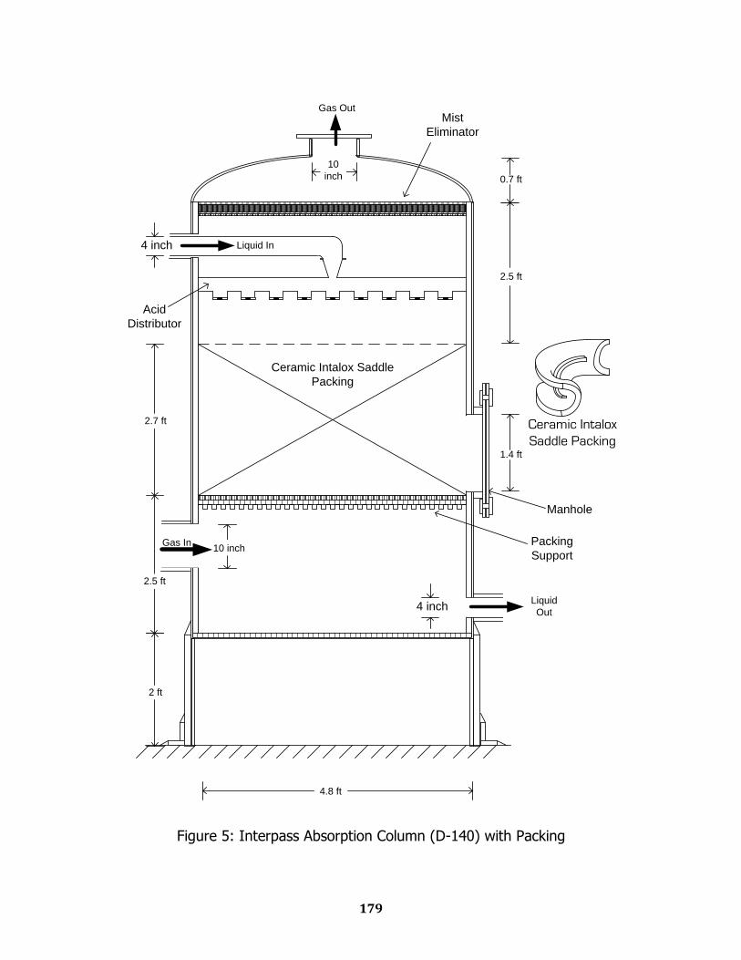
179
Ceramic Intalox
Saddle Packing
2.7 ft
2.5 ft
4 inch Liquid In
Gas In10 inch
2.5 ft
10
inch
1.4 ft
4.8 ft
Liquid
Out
Gas Out
4 inch
2 ft
0.7 ft
Ceramic Intalox Saddle
Packing
Mist
Eliminator
Acid
Distributor
Packing
Support
Manhole
Figure 5: Interpass Absorption Column (D-140) with Packing
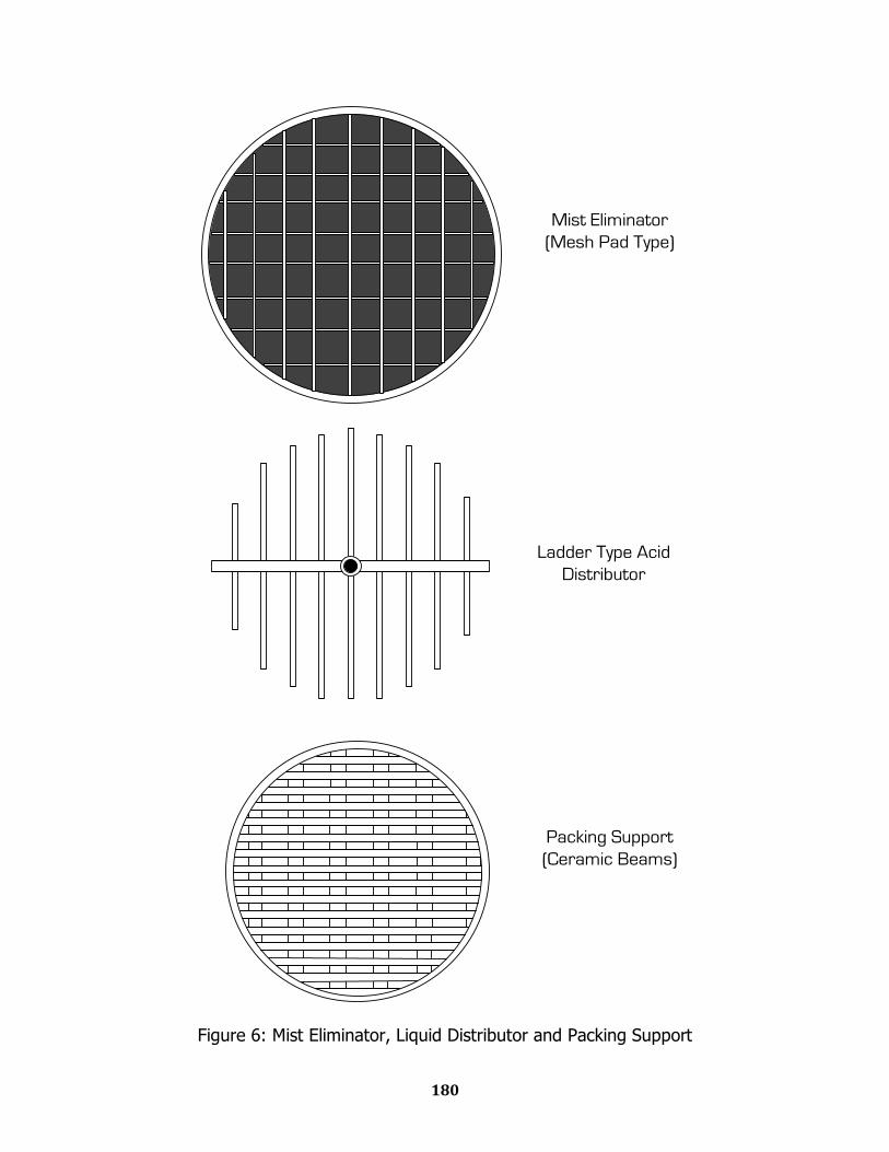
180
Mist Eliminator
(Mesh Pad Type)
Ladder Type Acid
Distributor
Packing Support
(Ceramic Beams)
Figure 6: Mist Eliminator, Liquid Distributor and Packing Support
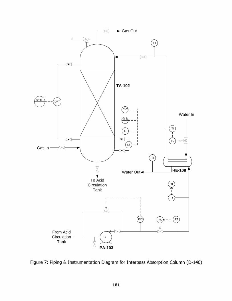
181
DPT
LT
DPAH
LI
LLA
HLA
PIC FTFC
TT
TI
FI
TI
To Acid
Circulation
Tank
From Acid
Circulation
Tank
TC
Water In
TI
Water Out
Gas In
Gas Out
TA-102
HE-108
PA-103
Figure 7: Piping & Instrumentation Diagram for Interpass Absorption Column (D-140)
13.3
Waste Heat Boiler-2 Design
Equipment Sizing
Mechanical Design
Engineering Drawing
P & ID Diagram
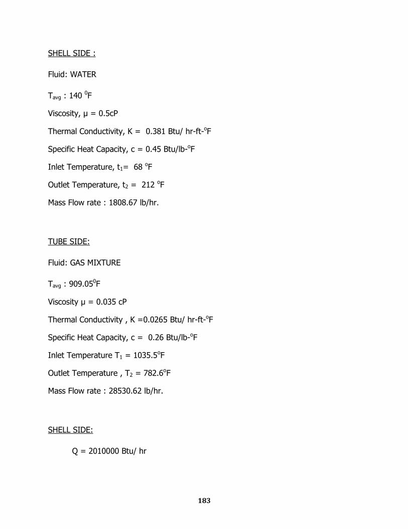
183
SHELL SIDE :
Fluid: WATER
Tavg : 140 0F
Viscosity, μ = 0.5cP
Thermal Conductivity, K = 0.381 Btu/ hr-ft-oF
Specific Heat Capacity, c = 0.45 Btu/lb-oF
Inlet Temperature, t1= 68 oF
Outlet Temperature, t2 = 212 oF
Mass Flow rate : 1808.67 lb/hr.
TUBE SIDE:
Fluid: GAS MIXTURE
Tavg : 909.050F
Viscosity μ = 0.035 cP
Thermal Conductivity , K =0.0265 Btu/ hr-ft-oF
Specific Heat Capacity, c = 0.26 Btu/lb-oF
Inlet Temperature T1 = 1035.5oF
Outlet Temperature , T2 = 782.6oF
Mass Flow rate : 28530.62 lb/hr.
SHELL SIDE:
Q = 2010000 Btu/ hr
184
LMTD CALCULATION:
Cold fluid on the shell side.
Hot fluid on the tube side.
LMTD =
= 767.760 F
R =
= 1.75625
S =
= 0.148837209
From graph 18(Kern):
FT = 0.98
Corrected LMTD = 767.76 × 0.98 = 752.41 oF
Now, Table 8(Kern) used for assuming UD
For, Gas – Water overall UD range is (2-50)Btu/ hr ft2 oF
Let, UD = 45 Btu/ hr ft2 oF
Heat transfer area calculation
Q = UD ×A×(corrected LMTD)
A
=
= 59.5 ft2
185
TUBE SELECTION:
OD= ¾ in
BWG = 16
ID = 0.62 in
Length of tube, L = 16ft
Surface area per unit length, a‟‟ = 0.1963 ft
1 in square pitch.
No. of tubes,
Nt =
‟‟ =
= 19
Nearest count:
¾ in OD, 1 in square pitch
No. of tubes, = 26 (2-pass) [From table 9, Kern]
Shell ID 8 in (from table 9 KERN, corresponding value of No. of tubes)
So, A= 26 × 0.1963 × 16 ft2
= 81.66 ft2
Corrected coefficient
=
= 32.761 Btu/ hr ft2 oF
186
TUBE SIDE:
Flow area per tube, = 0.302 in2
(table 10 KERN)
=
=
= 0.0273 ft2
Gt=
=
= 1052956.595 lb/ hr ft2
Tube inner dia, D = 0.62/12 =0.0517 ft
Reynold‟s no ,
μ =
= 642299.3789
1000 [ref:11]
μ
[assume
μ
μ = 1]
= 1000
= 482.213 Btu/hr-ft2-F
= ×
= 482.213 ×
= 398.63 Btu/hr-ft2-F
187
SHELL SIDE
Clearance, C‟ = 0.25
Baffle- space, B =
=
in.
Pitch, Pt = 1 in square Pitch
Flow area, as =
=
= 0.0222 ft2
Mass velocity, Gs=
=
= 81390.26 lb/hr ft2
Equivalent Diameter, De =
π
π = 0.07895 ft.
Reynold‟s no , 5310.73
40 (figure 28 KERN)
μ
[assume
μ
μ = 1]
= 217.425 (Btu/hr*ft2*F)
Clean heat transfer coefficient, =
=
= 140.69
Dirt factor, =
=
= 0.0234
Theoretical = 0.0001
Here calculated value is greater than theoretical value.
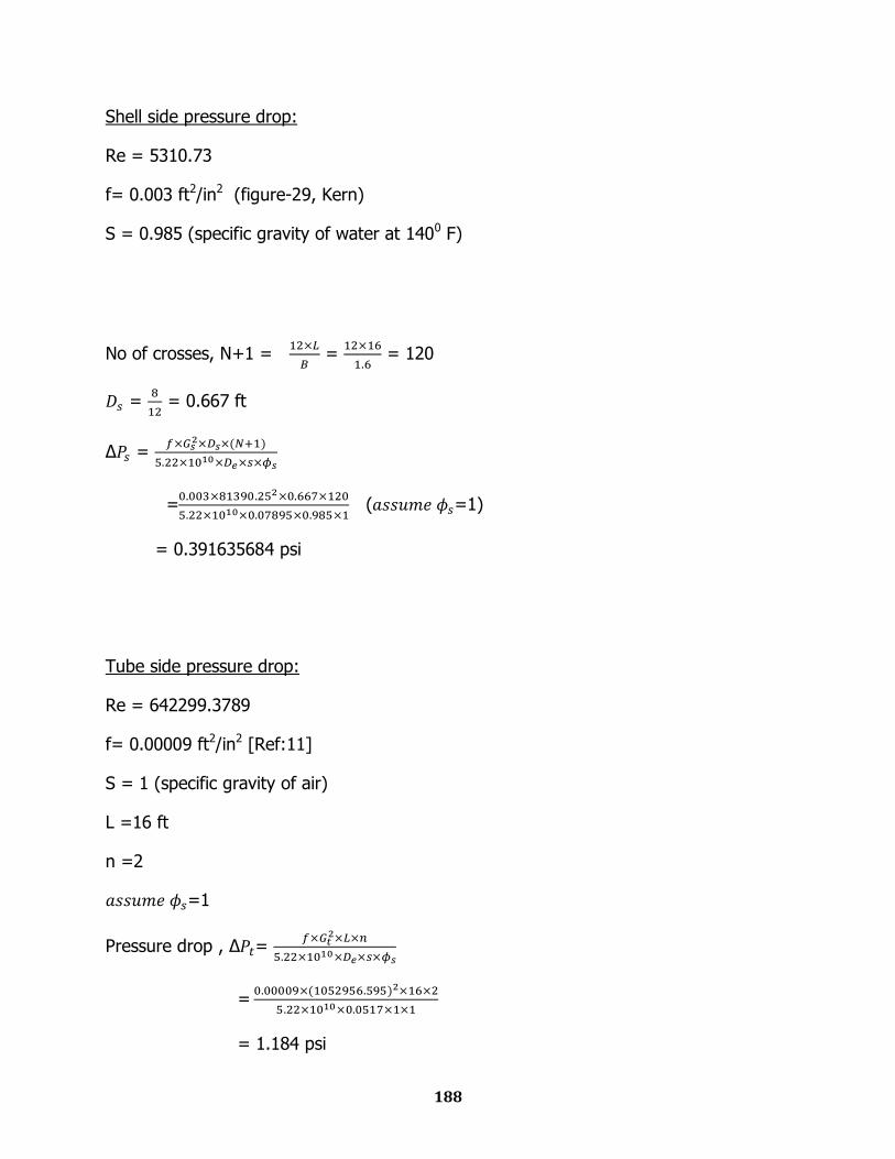
188
Shell side pressure drop:
Re = 5310.73
f= 0.003 ft2/in2 (figure-29, Kern)
S = 0.985 (specific gravity of water at 1400 F)
No of crosses, N+1 =
=
= 120
=
= 0.667 ft
Δ =
=
( =1)
= 0.391635684 psi
Tube side pressure drop:
Re = 642299.3789
f= 0.00009 ft2/in2 [Ref:11]
S = 1 (specific gravity of air)
L =16 ft
n =2
=1
Pressure drop , Δ =
=
= 1.184 psi
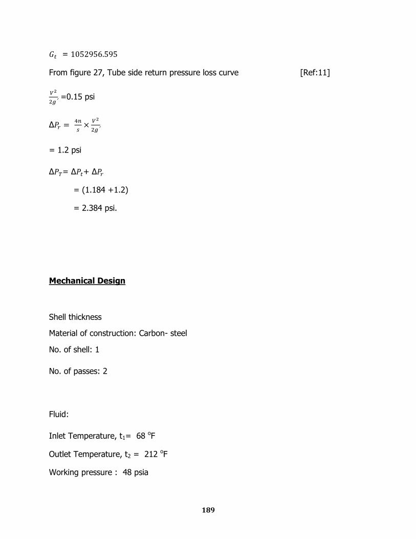
189
=
From figure 27, Tube side return pressure loss curve [Ref:11]
=0.15 psi
Δ
= 1.2 psi
Δ = Δ + Δ
= (1.184 +1.2)
= 2.384 psi.
Mechanical Design
Shell thickness
Material of construction: Carbon- steel
No. of shell: 1
No. of passes: 2
Fluid:
Inlet Temperature, t1= 68 oF
Outlet Temperature, t2 = 212 oF
Working pressure : 48 psia
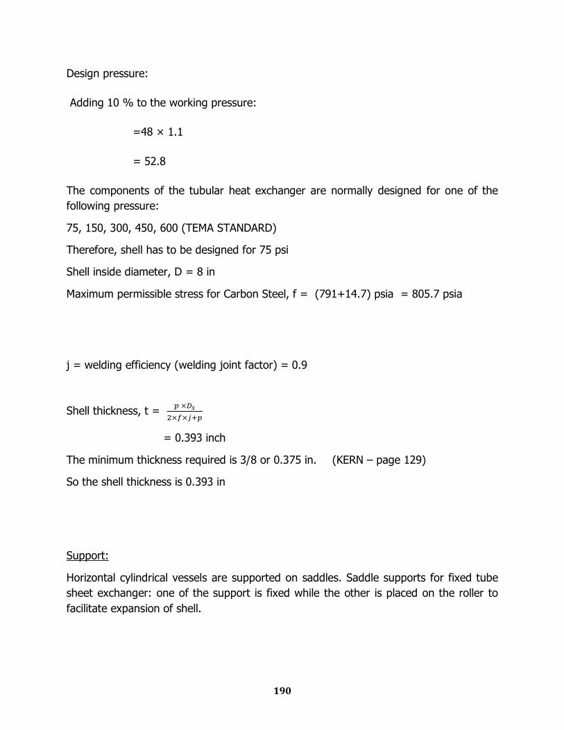
190
Design pressure:
Adding 10 % to the working pressure:
=48 × 1.1
= 52.8
The components of the tubular heat exchanger are normally designed for one of the
following pressure:
75, 150, 300, 450, 600 (TEMA STANDARD)
Therefore, shell has to be designed for 75 psi
Shell inside diameter, D = 8 in
Maximum permissible stress for Carbon Steel, f = (791+14.7) psia = 805.7 psia
j = welding efficiency (welding joint factor) = 0.9
Shell thickness, t =
= 0.393 inch
The minimum thickness required is 3/8 or 0.375 in. (KERN – page 129)
So the shell thickness is 0.393 in
Support:
Horizontal cylindrical vessels are supported on saddles. Saddle supports for fixed tube
sheet exchanger: one of the support is fixed while the other is placed on the roller to
facilitate expansion of shell.
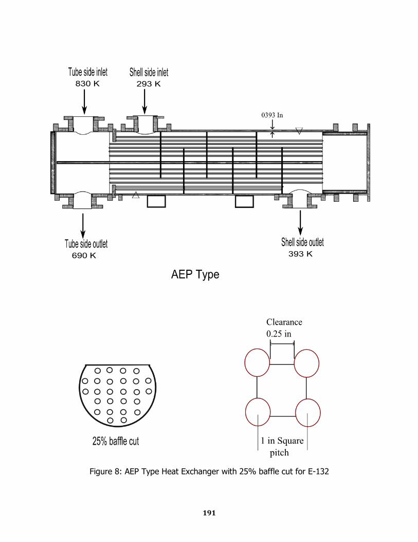
191
Figure 8: AEP Type Heat Exchanger with 25% baffle cut for E-132
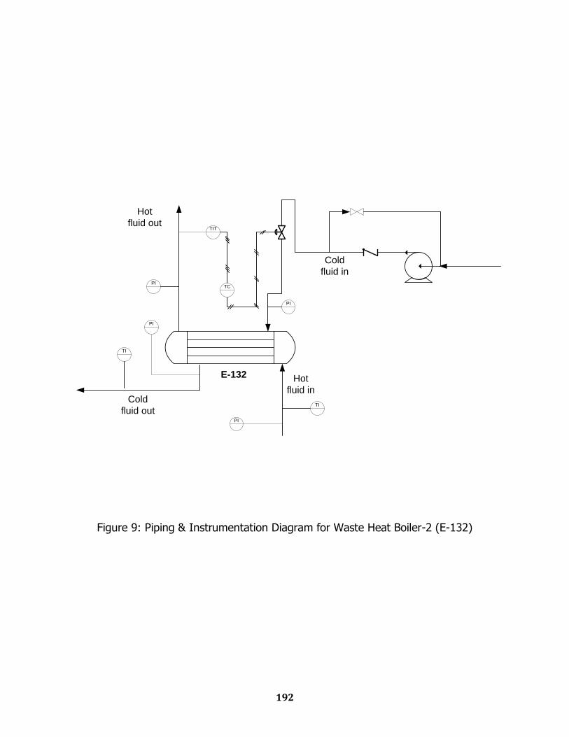
192
E-132
PI
TIT
TCPI
PI
TI
TI
PI
Hot
fluid in
Hot
fluid out
Cold
fluid out
Cold
fluid in
Figure 9: Piping & Instrumentation Diagram for Waste Heat Boiler-2 (E-132)
13.4
Storage Tank Design
Equipment Sizing
Mechanical Design
Engineering Drawing
P & ID Diagram
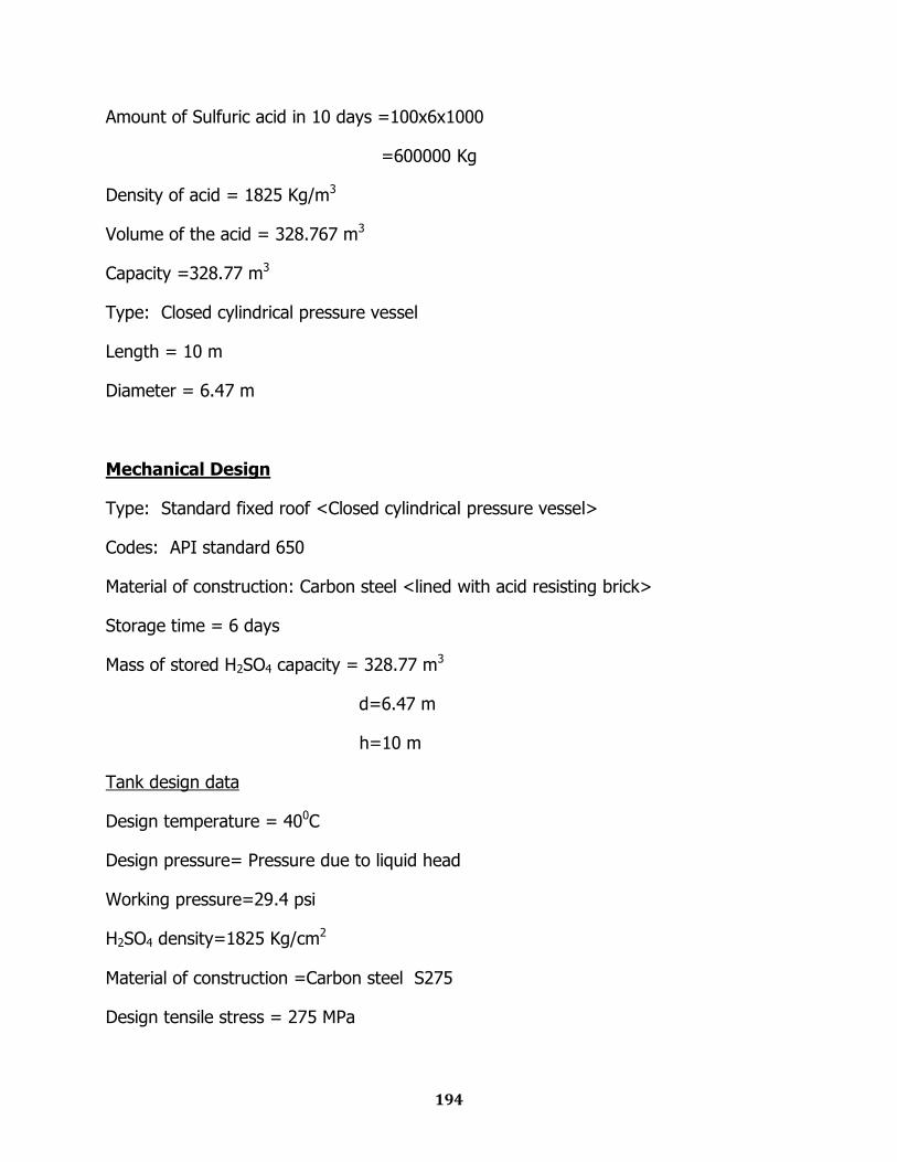
194
Amount of Sulfuric acid in 10 days =100x6x1000
=600000 Kg
Density of acid = 1825 Kg/m3
Volume of the acid = 328.767 m3
Capacity =328.77 m3
Type: Closed cylindrical pressure vessel
Length = 10 m
Diameter = 6.47 m
Mechanical Design
Type: Standard fixed roof <Closed cylindrical pressure vessel>
Codes: API standard 650
Material of construction: Carbon steel <lined with acid resisting brick>
Storage time = 6 days
Mass of stored H2SO4 capacity = 328.77 m3
d=6.47 m
h=10 m
Tank design data
Design temperature = 400C
Design pressure= Pressure due to liquid head
Working pressure=29.4 psi
H2SO4 density=1825 Kg/cm2
Material of construction =Carbon steel S275
Design tensile stress = 275 MPa
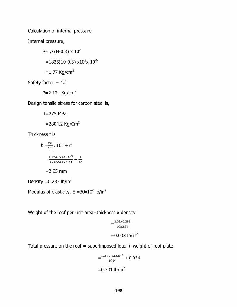
195
Calculation of internal pressure
Internal pressure,
P= ρ (H-0.3) x 102
=1825(10-0.3) x102x 10-6
=1.77 Kg/cm2
Safety factor = 1.2
P=2.124 Kg/cm2
Design tensile stress for carbon steel is,
f=275 MPa
=2804.2 Kg/Cm2
Thickness t is
t =
=
=2.95 mm
Density =0.283 lb/in3
Modulus of elasticity, E =30x106 lb/in2
Weight of the roof per unit area=thickness x density
=
=0.033 lb/in2
Total pressure on the roof = superimposed load + weight of roof plate
=
=0.201 lb/in2
196
The slope of the roof,
Sinθ=
=
=0.55
θ=33.1 0
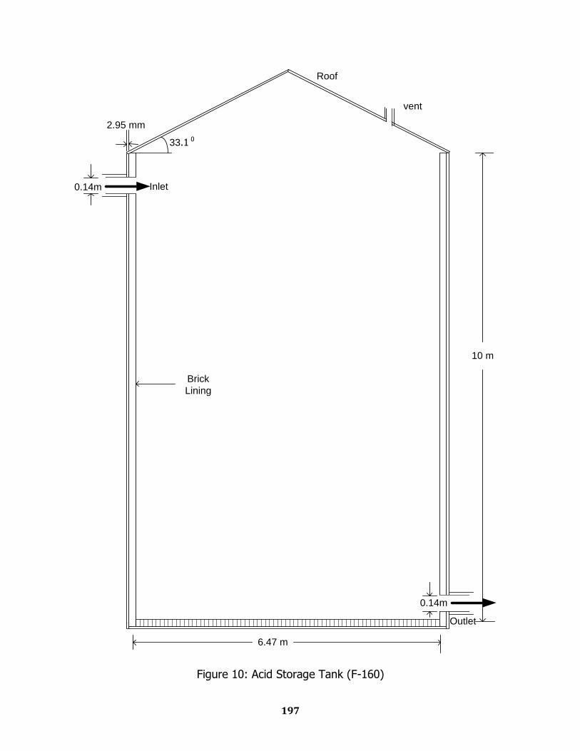
197
33.1 0
10 m
6.47 m
Brick
Lining
Inlet
Outlet
Roof
0.14m
0.14m
2.95 mm
vent
Figure 10: Acid Storage Tank (F-160)
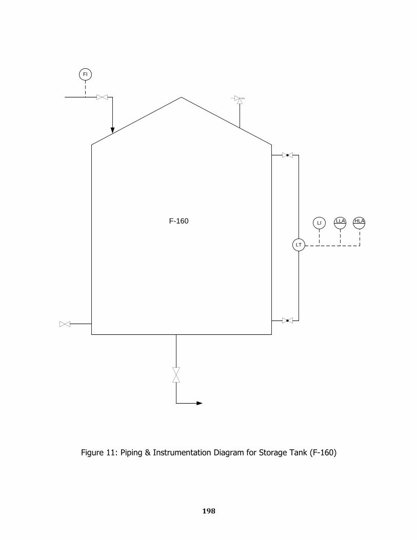
198
LT
LI LLA HLA
FI
F-160
Figure 11: Piping & Instrumentation Diagram for Storage Tank (F-160)

Chapter Fourteen
Plot Plan & Equipment Layout
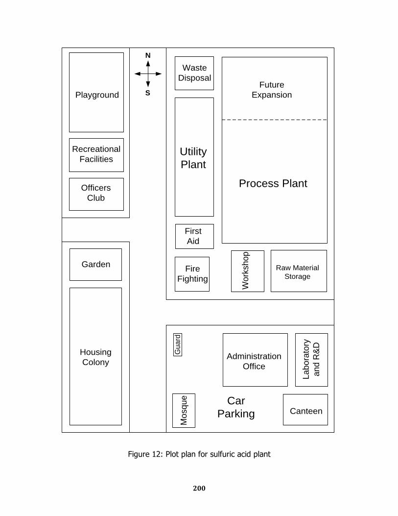
200
Housing
Colony
Garden
Officers
Club
Recreational
Facilities
Playground
Gu
ard
Car
Parking Canteen
Administration
Office
La
bo
rato
ry
an
d R
&D
Fire
Fighting
First
AidW
ork
sh
op
Raw Material
Storage
Waste
Disposal
Utility
Plant
Mo
sq
ue
Process Plant
Future
Expansion
N
S
Figure 12: Plot plan for sulfuric acid plant
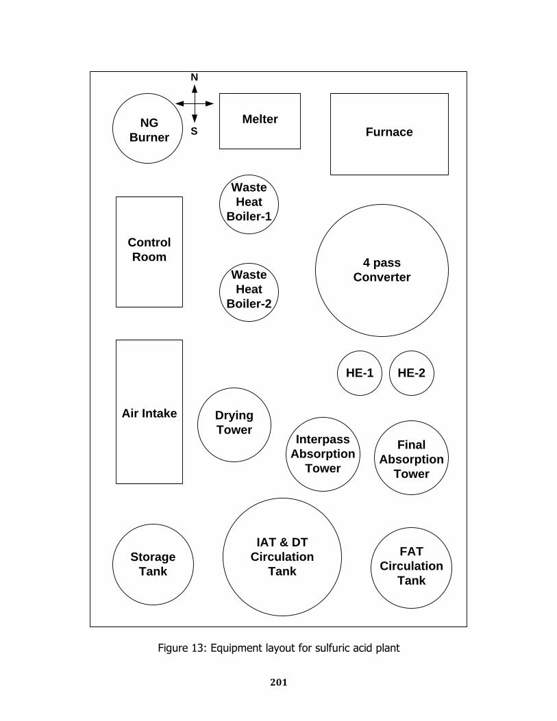
201
Control
Room
Air Intake
NG
Burner
Melter
Waste
Heat
Boiler-1
Waste
Heat
Boiler-2
Drying
TowerInterpass
Absorption
Tower
Final
Absorption
Tower
HE-1 HE-2
4 pass
Converter
Furnace
FAT
Circulation
Tank
IAT & DT
Circulation
Tank
Storage
Tank
N
S
Figure 13: Equipment layout for sulfuric acid plant
Chapter Fifteen
Estimation of
Total Capital Investment
And Production Cost
203
Cost Estimation of Major Units:
Blower (G-112)
Capacity = 298.77 Hp
For 298.77 HP capacity, cost = $ 1.1 105 (From figure 12.28 ref: 16)
Drying Tower(D-110)
Tower height = 11 m
Tower inner diameter = 1.295 m
Thickness = 8 mm
Outer diameter = 1.303 m
Volume = 0.018 m3
Density of carbon steel = 7850 kg/ m3
Weight of carbon steel = V × ρ = 0.018 × 7850 = 1413 kg
Form figure 15.10 for 1413 kg cost = $ 2 104
Waste heat boiler 1 (E-131)
Heat transfer surface area = 163.32 ft2 = 15.17 m2
Form figure 14.19 (ref: 16)
For 15.17 m2 surface area purchased cost = $ 8 103
Waste heat boiler 2(E-132)
Heat transfer surface area = 81.66 ft2 = 7.586 m2
Form figure 14.19 (ref: 16)
For 7.586 m2 surface area purchased cost = $ 3.2 103
204
Converter(R-130)
Converter height = 20.85 m
Converter inner diameter = 3.66 m
Converter Thickness = 7 mm
Converter Outer diameter = 3.667 m
Converter Volume = 0.84 m3
Density of carbon steel = 7889 kg/ m3
Weight of carbon steel = V × ρ
= 0.81 × 7889 = 6626 kg
Form figure 15.10 for 6626 kg cost = $ 1 105
Heat exchanger 1(E-133)
Heat transfer surface area = 163.32 ft2 = 15.17 m2
Form figure 14.19 (ref: 16)
For 15.17 m2 surface area purchased cost = $ 8 103
Heat exchanger 2(E-142)
Heat transfer surface area = 163.32 ft2 = 15.17 m2
Form figure 14.19 (ref: 16)
For 15.17 m2 surface area purchased cost = $ 8 103
205
Final Absorbsion Tower (D-150)
Tower height =3.633 m
Tower inner diameter = 1.3736 m
Thickness = 8 mm
Outer diameter = 1.3816 m
Volume = 0.063 m3
Density of carbon steel = 7850 kg/ m3
Weight of carbon steel = V × ρ
= 0.063 × 7850 = 494 kg
Form figure 15.10 for 494 kg cost = $ 1.1 104
Intermediate Absorption Tower(D-140)
Tower height =2.56 m
Tower inner diameter = 1.467 m
Thickness = 8 mm
Outer diameter = 1.483 m
Volume = 0.095 m3
Density of carbon steel = 7850 kg/ m3
Weight of carbon steel = V × ρ
= 0.095 × 7850 kg =745.75 kg
Form figure 15.10 for 745.75 kg cost = $ 1.4 104
206
Economizer (E-143)
Heat transfer surface area = 81.66 ft2 = 7.586 m2
Form figure 14.19 (ref: 16)
For 7.586 m2 surface area purchased cost = $ 3.2 103
Super heater economizer(E-151)
Heat transfer surface area = 163.32 ft2 = 15.17 m2
Form figure 14.19 (ref: 16)
For 15.17 m2 surface area purchased cost = $ 8 103
Circulation tank (F-154)
Tank height = 4.48 m
Tank inner diameter = 2.24 m
Tank thickness = 8 mm
Tank outer diameter = 2.248 m
Tank volume = 0.126 m3
Density of carbon steel = 7850 kg/ m3
Weight of carbon steel = V × ρ
= 0.126 × 7850 = 992 kg
Form figure 15.10 for 992 kg cost = $ 1.5 104
207
Circulation tank ( F-144):
Tank height = 4.72 m
Tank inner diameter = 2.36 m
Tank thickness = 8 mm
Tank outer diameter = 2.368 m
Tank volume = 0.14 m3
Density of carbon steel = 7850 kg/ m3
Weight of carbon steel = V × ρ
= 0.14 × 7850 = 1100 kg
Form figure 15.10 for 1100 kg cost = $ 1.6 104
Pumps
From figure 12.20 (ref: 16)
according to the capacity
Pump 1 (L-122) , cost = $ 2000
Pump 2 (L-153), cost = $ 2200
Pump 3 (L-145), cost = $ 3000
Pump 4 (L-146), cost = $ 2200
Pump 5 (L-161), cost = $ 2200
Cooler 1(E-152)
Heat transfer surface area = 40.83 ft2 = 3.79 m2
Form figure 14.19 (ref: 16)
For 3.79 m2 surface area purchased cost = $ 3 103
208
Cooler 2(E-141)
Heat transfer surface area = 238.7 ft2 = 22.18 m2
Form figure 14.19 (ref: 16)
For 22.18 m2 surface area purchased cost = $ 5 103
Cooler 3(E-162)
Heat transfer surface area = 238.7 ft2 = 22.18 m2
Form figure 14.19 (ref: 16)
For 22.18 m2 surface area purchased cost = $ 5 103
Storage tank(F-160)
Tower height = 10 m
Tower inner diameter = 6.47 m
Thickness = 8 mm
Outer diameter = 6.473 m
Volume = 0.3 m3
Density of carbon steel = 7850 kg/ m3
Weight of carbon steel = V × ρ
= 0.3 × 7850 = 2355 kg
Form figure 15.10 for 2355 kg cost = $ 2.6 104
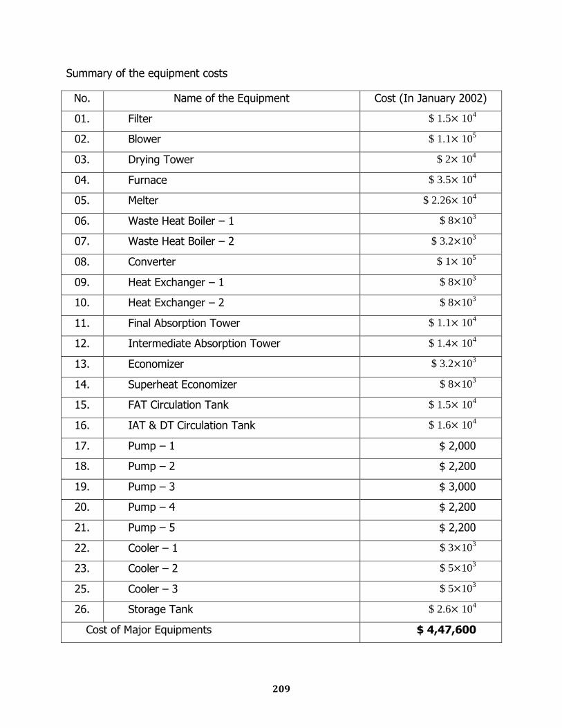
209
Summary of the equipment costs
No. Name of the Equipment Cost (In January 2002)
01. Filter $ 1.5 104
02. Blower $ 1.1 105
03. Drying Tower $ 2 104
04. Furnace $ 3.5 104
05. Melter $ 2.26 104
06. Waste Heat Boiler – 1 $ 8 103
07. Waste Heat Boiler – 2 $ 3.2 103
08. Converter $ 1 105
09. Heat Exchanger – 1 $ 8 103
10. Heat Exchanger – 2 $ 8 103
11. Final Absorption Tower $ 1.1 104
12. Intermediate Absorption Tower $ 1.4 104
13. Economizer $ 3.2 103
14. Superheat Economizer $ 8 103
15. FAT Circulation Tank $ 1.5 104
16. IAT & DT Circulation Tank $ 1.6 104
17. Pump – 1 $ 2,000
18. Pump – 2 $ 2,200
19. Pump – 3 $ 3,000
20. Pump – 4 $ 2,200
21. Pump – 5 $ 2,200
22. Cooler – 1 $ 3 103
23. Cooler – 2 $ 5 103
25. Cooler – 3 $ 5 103
26. Storage Tank $ 2.6 104
Cost of Major Equipments $ 4,47,600
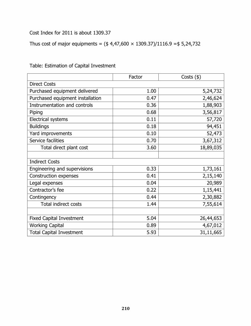
210
Cost Index for 2011 is about 1309.37
Thus cost of major equipments = ($ 4,47,600 × 1309.37)/1116.9 =$ 5,24,732
Table: Estimation of Capital Investment
Factor Costs ($)
Direct Costs
Purchased equipment delivered 1.00 5,24,732
Purchased equipment installation 0.47 2,46,624
Instrumentation and controls 0.36 1,88,903
Piping 0.68 3,56,817
Electrical systems 0.11 57,720
Buildings 0.18 94,451
Yard improvements 0.10 52,473
Service facilities 0.70 3,67,312
Total direct plant cost 3.60 18,89,035
Indirect Costs
Engineering and supervisions 0.33 1,73,161
Construction expenses 0.41 2,15,140
Legal expenses 0.04 20,989
Contractor‟s fee 0.22 1,15,441
Contingency 0.44 2,30,882
Total indirect costs 1.44 7,55,614
Fixed Capital Investment 5.04 26,44,653
Working Capital 0.89 4,67,012
Total Capital Investment 5.93 31,11,665
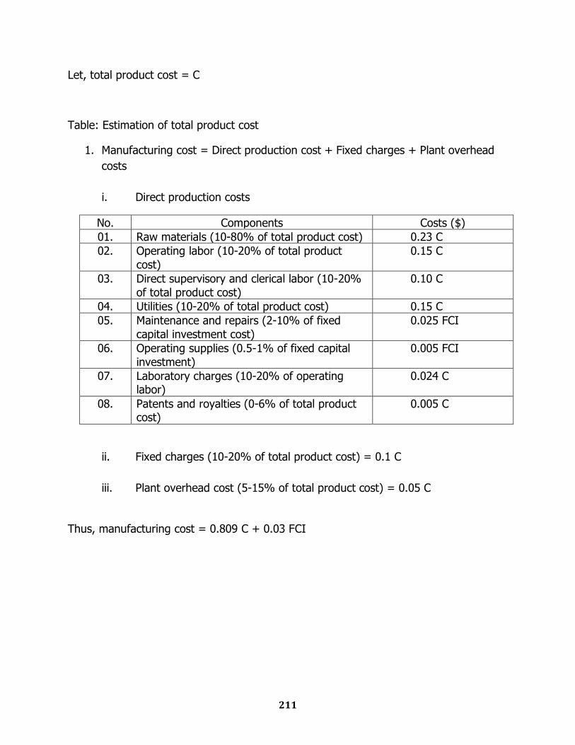
211
Let, total product cost = C
Table: Estimation of total product cost
1. Manufacturing cost = Direct production cost + Fixed charges + Plant overhead
costs
i. Direct production costs
No. Components Costs ($)
01. Raw materials (10-80% of total product cost) 0.23 C
02. Operating labor (10-20% of total product
cost)
0.15 C
03. Direct supervisory and clerical labor (10-20%
of total product cost)
0.10 C
04. Utilities (10-20% of total product cost) 0.15 C
05. Maintenance and repairs (2-10% of fixed
capital investment cost)
0.025 FCI
06. Operating supplies (0.5-1% of fixed capital
investment)
0.005 FCI
07. Laboratory charges (10-20% of operating labor)
0.024 C
08. Patents and royalties (0-6% of total product cost)
0.005 C
ii. Fixed charges (10-20% of total product cost) = 0.1 C
iii. Plant overhead cost (5-15% of total product cost) = 0.05 C
Thus, manufacturing cost = 0.809 C + 0.03 FCI
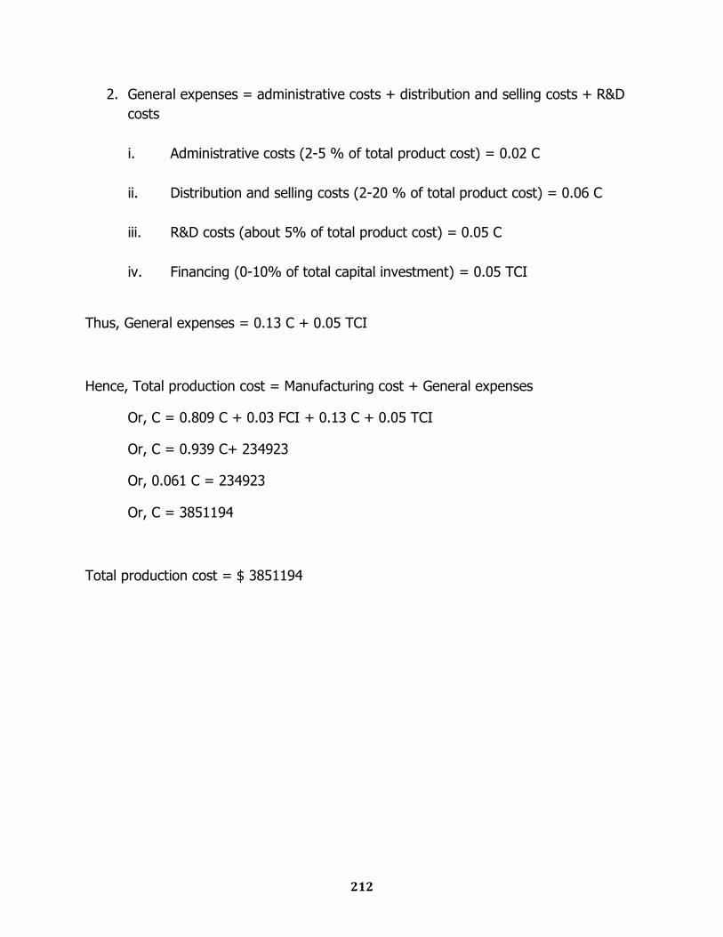
212
2. General expenses = administrative costs + distribution and selling costs + R&D
costs
i. Administrative costs (2-5 % of total product cost) = 0.02 C
ii. Distribution and selling costs (2-20 % of total product cost) = 0.06 C
iii. R&D costs (about 5% of total product cost) = 0.05 C
iv. Financing (0-10% of total capital investment) = 0.05 TCI
Thus, General expenses = 0.13 C + 0.05 TCI
Hence, Total production cost = Manufacturing cost + General expenses
Or, C = 0.809 C + 0.03 FCI + 0.13 C + 0.05 TCI
Or, C = 0.939 C+ 234923
Or, 0.061 C = 234923
Or, C = 3851194
Total production cost = $ 3851194

Chapter Sixteen
Economic Analysis
214
Calculation of total income from sales
Production of H2SO4 (98.5 wt%) = 4104.17 kg/hr = 3,59,52,500 kg/yr
Market price = 10 tk per kg
Annual sales = 359,52,500 kg/yr × 10 tk/kg × $ 1/70 tk
= $ 51,36,072/yr
Calculation of rate of return
VAT = 2.5 %
Total sales after VAT = $ 50,07,670/yr
Total annual income = $ 50,07,670 - $ 38,51,194= $ 11,56,476/yr
Tax on income = 20%
Net profit after tax = $ 9,25,181/yr
Percent rate of return = net profit after tax/total capital investment
= 9,25,181/31,11,665
= 29.73 %
Turnover ratio
Turnover ratio = gross annual sales / fixed-capital investment
= 51,36,072/26,44,653
= 1.94
215
Depreciation of FCI
Project life = 15 yrs
Salvage Value at the end of the project life = 10% of FCI
Depreciable FCI = 0.9 × FCI = $ 23,80,188
Now depreciation by sinking fund, with 15% interest rate
= $ 23,80,188 (A/P, 15%, 15)
= $ 4,07,053
Table: Calculation of Payback Period
End of year k Net Cash Flow Cumulative PW at i=0%/yr through Year k
Present Worth of Cash Flow at i=15%/yr
Cumulative PW at i=15%/yr through Year k
0 -31,11,665 -31,11,665 -31,11,665 -31,11,665
1 925181 -2186484 804505 -2307160
2 925181 -1261303 699570 -1607590
3 925181 -336122 608322 -999268
4 925181 +589059 528975 -470293
5 925181 459978 -10315
6 925181 399981 389666
216
Payback period
Payback period (without interest) = 4 yr
Payback period (with interest) = 6 yr
Calculation of IRR by PW method
Let, IRR = i%
By PW method
-TCI + Annual Income (P/A, i%, 15) + Salvage value (P/F, i%, 15) = 0
Or, - $ 31,11,665 + $ 9,25,181 (P/A, i%, 15) + $ 2,64,465 (P/F, i%, 15) = 0
Or, - $ 31,11,665 + $ 9,25,181
+ $ 2,64,465
= 0
Or, i = 0.292
Thus, IRR = 29.2 %
Since IRR>MARR, the project is acceptable.
NPV Calculation with MARR=15%
NPV (15%) = -TCI + Annual Income (P/A, 15%, 15) + Salvage value (P/F, 15%, 15)
= - $ 31,11,665 + $ 9,25,181 (P/A, 15%, 15) + $ 2,64,465 (P/F, 15%, 15)
= - $ 31,11,665 + $ 5409876 + $ 32,501
= $ 23,30,712 > 0
So the investment is economically acceptable.

References
218
1. Backharst, R. J., and Harker, H. J., "Process Plant Design", Heinemann
Educational Books, London, 1973.
2. Daugherty, R.L., Franzani, J.B., and Finnemore, E.J., "Fluid Mechanics with
Engineering Applications", 1989.
3. Devenport, W.G., King, M. J., “Sulfuric Acid Manufacture”, Elsevier Science,
2005
4. Duecker, W.W., West, J.R., “The Manufacture of Sulfuric Acid”, Reinhold
Publishing Corporation, New York, 1959.
5. Felder, M.R., and Rousseau, R.W., "Elementary Principles of Chemical
Engineering", John Willy & Sons, 2nd Edution.
6. Foust, S., Alan; Wenzel, A.L., Clump, W.; C.; Maus Louis, and Andersen B., L.,
"Principles of Unit Operation", John Willy & Sons, 1980.
7. George, T.A., "Shrieves Chemical Process Industries", McGraw-Hill Book Co., 5th
Edition, International Edition.
8. Halman, P.J., "Heat Transfer", McGraw-Hill Book Co., 7th Edition, SI Units.
9. Hill, Charles G., “An Introduction to Chemical Engineering Kinetics & Reactor
Design”, John Wiley & Sons, 1977
10. Joshi, M.V., "Process Equipment Design", The Macmillan Company, 1976.
219
11. Kern, D.Q., "Process Heat Transfer", McGraw-Hill International Book Co., Japan,
International Student Edition, 1983.
12. Ludwig, E.E., "Applied Process Design For Chemical And Petrochemical Plants",
Volume Two, Gulf Publishing Company, U.S.A. Second Edition.
13. Meketta, J., John, "Piping Design Handbook", Marcal Dekkar Inc., New York,
1992.
14. Meketta, J., John, and Connigham A., W., "Encyclopedia of Chemical Processing
and Design", Marcal Dekkar Inc., New York, 1984.
15. Perry, Robert, H.; Green D., W., and Maloney, James O., "Perry's Chemical
Engineer's Hand Book", McGraw-Hill, Inc., 7th International Edition, April 1997.
16. Peters, M., S., and Timmerhaus, K., D., "Plant Design and Economics for
Chemical Engineer", McGraw-Hill, Inc., 4th Edition.
17. Shah, R.K., Subbarao, E.C., “Heat Transfer Equipment Design”, Hemisphere
Publishing Corp, Washington
18. Sinnott,R.K., „Coulson & Richardson‟s Chemical Engineering‟, volume 6,
Butterworth Heinemann, 3rd Edition, 2003
Recommended