Orion Parachute Riser Cutter Development
Sirri Oguz1
NASA Johnson Space Center, Houston, TX, 77058
Frank Salazar2
NASA Johnson Space Center, Houston, TX, 77058
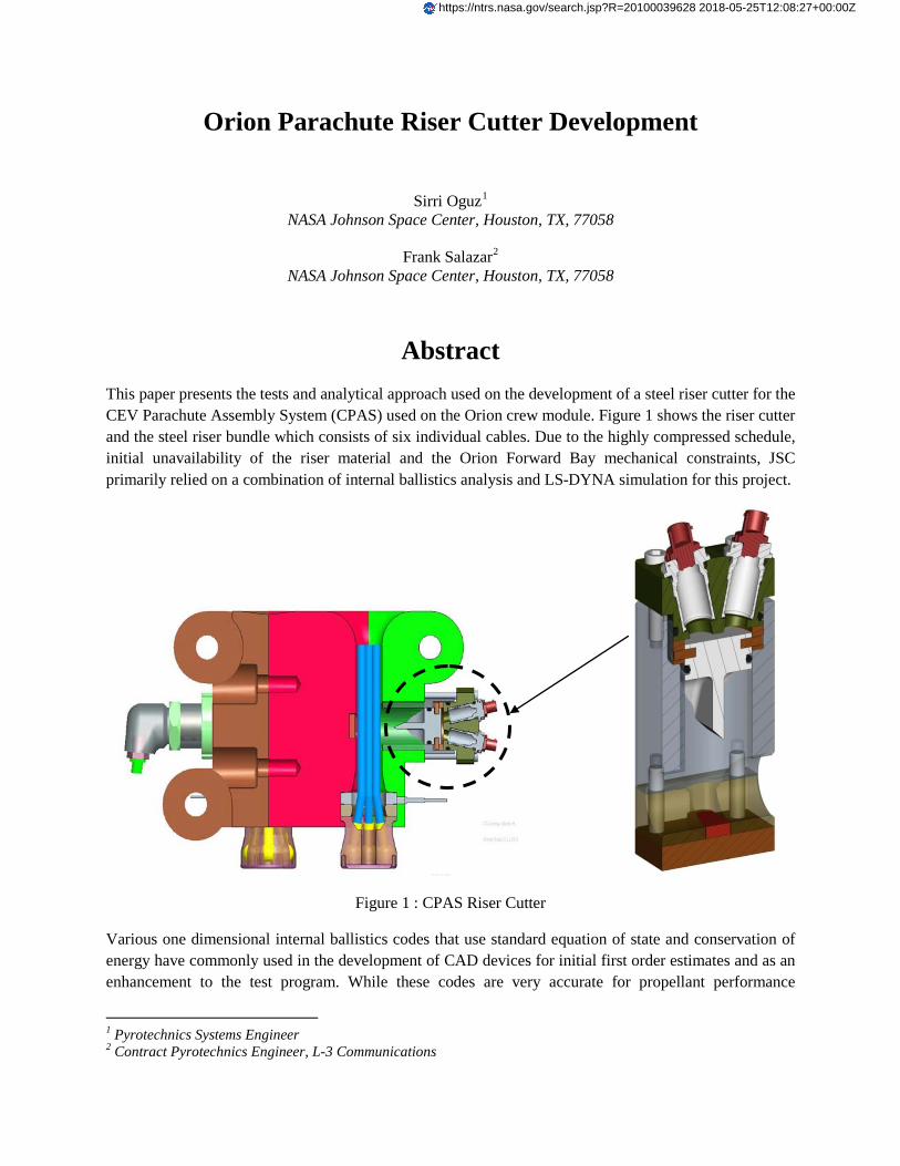
Abstract This paper presents the tests and analytical approach used on the development of a steel riser cutter for the CEV Parachute Assembly System (CPAS) used on the Orion crew module. Figure 1 shows the riser cutter and the steel riser bundle which consists of six individual cables. Due to the highly compressed schedule, initial unavailability of the riser material and the Orion Forward Bay mechanical constraints, JSC primarily relied on a combination of internal ballistics analysis and LS-DYNA simulation for this project.
Figure 1 : CPAS Riser Cutter
Various one dimensional internal ballistics codes that use standard equation of state and conservation of energy have commonly used in the development of CAD devices for initial first order estimates and as an enhancement to the test program. While these codes are very accurate for propellant performance
1 Pyrotechnics Systems Engineer 2 Contract Pyrotechnics Engineer, L-3 Communications
https://ntrs.nasa.gov/search.jsp?R=20100039628 2018-05-25T12:08:27+00:00Z
prediction, they usually lack a fully defined kinematic model for dynamic predictions. A simple piston device can easily and accurately be modeled using an equation of motion. However, the accuracy of analytical models is greatly reduced on more complicated devices with complex external loads, nonlinear trajectories or unique unlocking features.
A 3D finite element model of CAD device with all critical features included can vastly improve the analytical ballistic predictions when it is used as a supplement to the ballistic code. During this project, LS-DYNA structural 3D model was used to predict the riser resisting load that was needed for the ballistic code. A Lagrangian model with eroding elements shown in Figure 2 was used for the blade, steel riser and the anvil. The riser material failure strain was fine tuned by matching the dent depth on the anvil with the actual test data. LS-DYNA model was also utilized to optimize the blade tip design for the most efficient cut.
Figure 2: Riser Cutter LS-DYNA Model
In parallel, the propellant type and the amount were determined by using CADPROG internal ballistics code. Initial test results showed a good match with LS-DYNA and CADPROG simulations.
Final paper will present a detailed roadmap from initial ballistic modeling and LS-DYNA simulation to the performance testing. Blade shape optimization study will also be presented.
Blade
Steel Riser bundle
Anvil
American Institute of Aeronautics and Astronautics
1
Orion Parachute Riser Cutter Development
Sirri Oguz1
NASA Johnson Space Center, Houston, TX, 77058
Frank Salazar2
NASA Johnson Space Center, Houston, TX, 77058
The parachute assembly is an integral part of the Orion crew module Landing and
Recovery System (LRS) and consists of two drogue and three main parachutes. A
pyrotechnic cutter is used to sever the drogue parachute riser lines during the terminal
descent phase of the mission and the main parachute riser lines shortly after splashdown.
An Orion vehicle configuration change required a change on riser material and created an
immediate need for a steel riser cutter to be used in the parachute drop tests. The development of this riser cutter with an extremely tight schedule required an accurate
analytical and simulation approach to meet the delivery date. An internal ballistic model
and a structural explicit hydrodynamic simulation were developed to support the Orion
parachute assembly test program.
Nomenclature
Ap = piston diameter
B = burn rate coefficient
C = propellant mass
Cv = specific heat at constant volume
EHL = heat loss
F = impetus
FEXT = external force (cable resisting load)
Ff = friction force m = piston mass
mp = mass of propellant gas produced
n = burn rate exponent
PC = chamber pressure
r = propellant burn rate
S = propellant surface area
T = gas temperature
To = isochoric flame temperature
VC = initial chamber volume
x = stroke
ρ = propellant mass density η = co-volume
I. Introduction
Orion parachute assembly riser cutter is a pyrotechnically actuated guillotine that is used to sever the drogue
and main parachute steel risers during final descent and landing phases. The riser lines consist of a bundle of six steel cables with a tensile load capacity of 16,000 pounds for each cable. The cutter assembly requires dual
pyrotechnic cartridges for redundancy; each initiated by a NASA Standard Initiator (NSI).
The focus of the present work was to perform a detailed analytical assessment of the cutter design, and test and
manufacture the test hardware for the Parachute Test Vehicle (PTV) drop tests. Figure 1 depicts the primary
1 Pyrotechnics Systems Engineer
2 Contract Pyrotechnics Engineer, L-3 Communications STRATIS

American Institute of Aeronautics and Astronautics
2
components of the riser cutter. The cutter consists of a steel blade, piston retainer, cutter housing, an anvil, shear
pins and dual cartridges. Upon receiving a firing signal, NSI’s ignite the cartridge assemblies. The blade which is
held in place with shear pins starts to stroke as soon as the cartridge output pressure shears the pins. After
approximately half an inch of stroke, the blade impacts the cable bundle and severs it. After the complete severance
of the riser bundle, blade penetrates into the steel anvil and finishes its stroke. One of the major factors driving the
cutter design was that the cutter must demonstrate performance margin by cutting the target with a single cartridge loaded with a reduced amount of propellant load (85%) and show no structural yielding when cutting with both
cartridges loaded at 115%. Furthermore, the cutter assembly is required to maintain structural integrity when tested
in a locked-shut condition with dual nominally loaded cartridges.
Figure 1. Riser Cutter Components
The flowerpot is a single structural element that retains each riser via a “puck”. The puck captures the cables
indivually using swaged fittings. The flowerpot also serves as a guide to channel the riser through the cutter. The
risers emerge from the guides and spread out to their respective parachutes (hence the name flower pot). Figure 2
shows the interface between the flowerpot and the cutter assemblty.
Figure 2. Riser Cutter / Flowerpot Interface
American Institute of Aeronautics and Astronautics
3
At the start of the development effort, the flowerpot was still in design and integrated cutter envelope was not
determined. Some dimensions were known but the effort was fluid and would force the cutter envelope to move.
This forced the initial efforts to analyze the blade and target in order to get estimates on energy losses due to wear
on blade leading edge. Seven strands of a substitute cable were analyzed in place of six flight cables to account for
work hardening and strength deficiencies compared to the actual flight cable. Variations in blade edge and shape were analyzed. Unfortunately the most efficient blade was not used because it drove and increased stroke and
envelope constraints could not be maintained. The cutter envelope required a cutter outer diameter that was
relatively small. The project imposed a standalone cutter which could not utilize the flowerpot structure and
effectively reduced the envelope even more. After the blade configuration was established, the piston and blade
standoff could be baselined. The decision was made to leverage the existing parachute textile strap cutter design
parameters (i.e. clearances, seals, test hardware). The use of a common and available propellant was required. This
enabled the analysis methods used to provide a quick estimate for propellant quantities prior to testing.
JSC primarily relied on a combination of internal ballistics analysis and nonlinear explicit finite elements
simulation for this project. These two mathematical approaches were used in tandem to establish the optimum
pyrotechnic charge while accurately predicting the resisting shear loads, the blade performance and the anvil
configuration.
CADPROG internal ballistics code was used to simulate the ballistic performance of the riser cutter. While
CADPROG is very accurate for propellant performance predictions, it requires external load input either from test
data or a high fidelity structural simulation code such as LS-DYNA. For the study presented here, LS-DYNA
structural model was used to predict the riser resisting loads that were needed for the ballistic analysis. LS-DYNA
model was also used to optimize the blade shape and the material and to estimate the reaction loads that the vehicle
encounters.
II. Internal Ballistic Analysis
CADPROG was originally developed by NSWC Indian Head Division and recently updated by JSC to enhance
the heat loss and external loading modules. It is a one-dimensional internal ballistics code that uses time-dependent
nonlinear equations of gas dynamics. The governing equations that need to be solved consist of conservation of
energy and mass as well as the Nobel-Abel equation of state.
The conservation of energy for stroking pyrotechnic devices such as a guillotine cutter is as follows:
(1)
Conservation of mass:
(2)
Propellant burn rate, r is a function of the space-average pressure and fits the experimental data of most
propellants in the form of following equation:
(3)
where B and n are constants based on the experimental data.
Nobel-Abel equation of state defines the relationship between the chamber pressure, volume and the temperature
as follows:
dt
Ed
dt
dxPA
dt
dmTc
dt
Tmdc HL
CP
p
v
p
v
)()(0 −−=
rSdt
dmp..ρ=
n
cBPr =
American Institute of Aeronautics and Astronautics
4
(4)
The chamber pressure derived from the equation of state is used to determine the acceleration of stroking mass using Newton’s second law.
(5)
In addition to the friction forces, the only external load the blade encounters is the resisting loads caused by the
riser bundle during the cut. Ideally, this force is determined by test or estimated based on the material strength.
However, the unusual configuration of the flight cable and the lack of flight configuration test hardware during the
initial development phase and the fact that the resisting loads are dependent on the blade velocity required the use of
a high fidelity explicit transient finite element model.
Hi-Temp was selected as the energetic material to be used on the cutter assembly design. Hi-Temp is an RDX
based propellant with relatively good ignition sensitivity at ambient pressure and a burn rate of about 1.6 in/sec at
5,000 psi and has a well established usage base on similar guillotine applications. In general, the published ballistic
properties of Hi-Temp match well with internal ballistic codes without significant tweaking. To verify and refine the
ballistic parameters, a sample Hi-Temp loaded cartridge was tested in a 4.2 cu-in closed bomb and the CADPROG
input parameters were baselined as shown in Fig.3. Only a minor adjustment was needed on published burn rate
coefficients.
Figure 3. Closed Bomb Data and Analysis
III. Finite Elements Model
To evaluate the riser cable shear resistance loads and the blade performance, an LS-DYNA Finite Elements
Analysis (FEA) model was created. LS-DYNA is an explicit FEA code that uses time integration to solve short
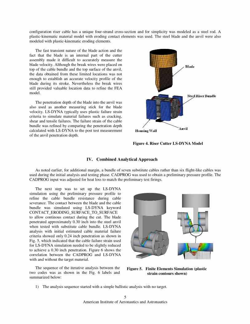
duration transient and highly nonlinear dynamic problems. Figure 4 shows the finite elements model used for this
study. The simplified FEA model consists of a blade, anvil, housing wall and the steel riser cable bundle. The flight
0
][T
TFmm
mCxAVP
pp
p
Pcc=−
−−+ η
ρ
extfPc FFAPdt
xdm −−=
2
2
American Institute of Aeronautics and Astronautics
5
configuration riser cable has a unique four-strand cross-section and for simplicity was modeled as a steel rod. A
plastic-kinematic material model with eroding contact elements was used. The steel blade and the anvil were also
modeled with plastic-kinematic eroding elements.
The fast transient nature of the blade action and the
fact that the blade is an internal part of the cutter assembly made it difficult to accurately measure the
blade velocity. Although the break wires were placed on
top of the cable bundle and the top surface of the anvil,
the data obtained from these limited locations was not
enough to establish an accurate velocity profile of the
blade during its stroke. Nevertheless the break wires
still provided valuable location data to refine the FEA
model.
The penetration depth of the blade into the anvil was
also used as another measuring stick for the blade
velocity. LS-DYNA typically uses plastic failure strain criteria to simulate material failures such as cracking,
shear and tensile failures. The failure strain of the cable
bundle was refined by comparing the penetration depth
calculated with LS-DYNA to the post test measurement
of the anvil penetration depth.
IV. Combined Analytical Approach
As noted earlier, for additional margin, a bundle of seven substitute cables rather than six flight-like cables was
used during the initial analysis and testing phase. CADPROG was used to obtain a preliminary pressure profile. The
CADPROG input was adjusted for heat loss to match the preliminary test firings.
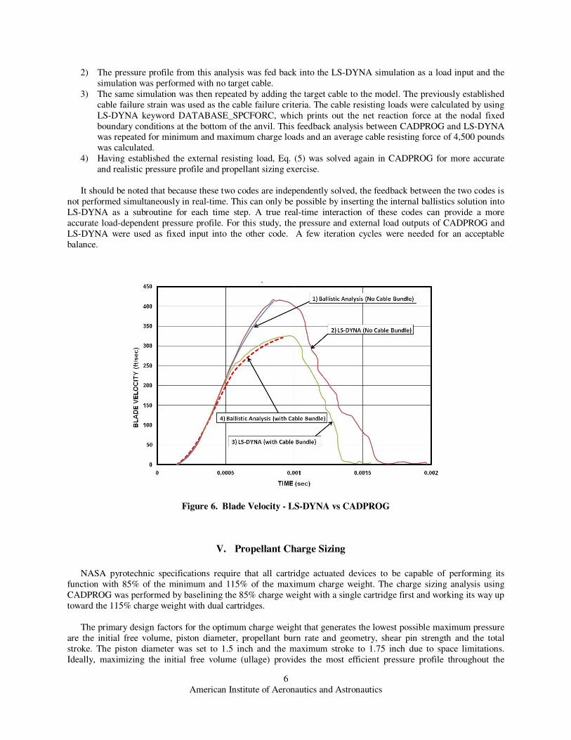
The next step was to set up the LS-DYNA
simulation using the preliminary pressure profile to
refine the cable bundle resistance during cable
severance. The contact between the blade and the cable
bundle was simulated using LS-DYNA keyword
CONTACT_ERODING_SURFACE_TO_SURFACE
to allow continous contact during the cut. The blade
penetrated approximately 0.30 inch into the steel anvil
when tested with substitute cable bundle. LS-DYNA
analysis with initial estimated cable material failure
criteria showed only 0.24 inch penetration as shown in
Fig. 5, which indicated that the cable failure strain used for LS-DYNA simulation needed to be slightly reduced
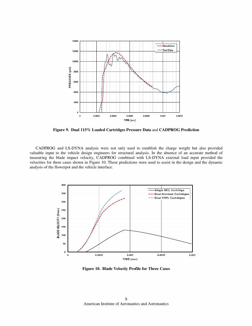
to achieve a 0.30 inch penetration. Figure 6 shows the
correlation between the CADPROG and LS-DYNA
with and without the target material.
The sequence of the iterative analysis between the
two codes was as shown in the Fig. 6 labels and
summarized below:
1) The analysis sequence started with a simple ballistic analysis with no target.
Figure 4. Riser Cutter LS-DYNA Model
Figure 5. Finite Elements Simulation (plastic
strain contours shown)
American Institute of Aeronautics and Astronautics
6
2) The pressure profile from this analysis was fed back into the LS-DYNA simulation as a load input and the
simulation was performed with no target cable.
3) The same simulation was then repeated by adding the target cable to the model. The previously established
cable failure strain was used as the cable failure criteria. The cable resisting loads were calculated by using
LS-DYNA keyword DATABASE_SPCFORC, which prints out the net reaction force at the nodal fixed
boundary conditions at the bottom of the anvil. This feedback analysis between CADPROG and LS-DYNA was repeated for minimum and maximum charge loads and an average cable resisting force of 4,500 pounds
was calculated.
4) Having established the external resisting load, Eq. (5) was solved again in CADPROG for more accurate
and realistic pressure profile and propellant sizing exercise.
It should be noted that because these two codes are independently solved, the feedback between the two codes is
not performed simultaneously in real-time. This can only be possible by inserting the internal ballistics solution into
LS-DYNA as a subroutine for each time step. A true real-time interaction of these codes can provide a more
accurate load-dependent pressure profile. For this study, the pressure and external load outputs of CADPROG and
LS-DYNA were used as fixed input into the other code. A few iteration cycles were needed for an acceptable
balance.
Figure 6. Blade Velocity - LS-DYNA vs CADPROG
V. Propellant Charge Sizing
NASA pyrotechnic specifications require that all cartridge actuated devices to be capable of performing its
function with 85% of the minimum and 115% of the maximum charge weight. The charge sizing analysis using
CADPROG was performed by baselining the 85% charge weight with a single cartridge first and working its way up
toward the 115% charge weight with dual cartridges.
The primary design factors for the optimum charge weight that generates the lowest possible maximum pressure
are the initial free volume, piston diameter, propellant burn rate and geometry, shear pin strength and the total
stroke. The piston diameter was set to 1.5 inch and the maximum stroke to 1.75 inch due to space limitations.
Ideally, maximizing the initial free volume (ullage) provides the most efficient pressure profile throughout the

American Institute of Aeronautics and Astronautics
7
power stroke. Within the design space and the structural limitation, the maximum possible volume was utilized. As a
result, the shear pin strength and the propellant weight remained the two major variables to be predicted for the
optimum design.
Figure 7 depicts the comparison of the ballistic analysis prediction to the test data for the single 85% cartridge.
Using the LS-DYNA resisting load predictions and the heat loss estimates based on the initial firings with substitute cable bundle, an excellent match was achieved between CADPROG simulation and the test data. Note that the
prediction curve was shifted manually to match the ignition delay.
Figure 7. Single 85% Loaded Cartridge Pressure Data and CADPROG Prediction
For a relatively short stroking CAD with small initial free volume such as this cutter assembly, the performance
difference between the 85% single cartridge and 115% dual cartridges can be huge. All structural margins of the
cutter assembly should be based on the maximum pressure obtained from the dual 115% cartridges or 1.2 times the
dual nominal cartridges, whichever is greater. CADPROG predictions for dual nominal and 115% cartridges were in
excellent agreement with the results obtained from test firings as shown in Figure 8 and 9.
Figure 8. Dual Nominally Loaded Cartridges Pressure Data and CADPROG Prediction
American Institute of Aeronautics and Astronautics
8
Figure 9. Dual 115% Loaded Cartridges Pressure Data and CADPROG Prediction
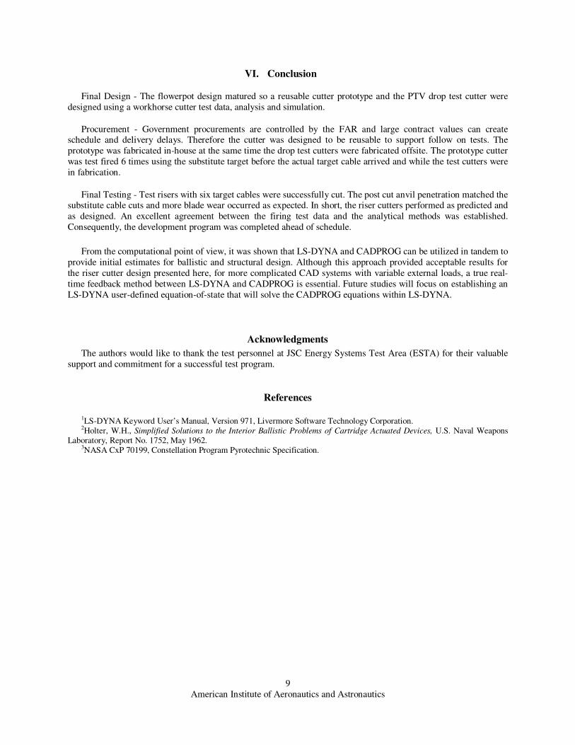
CADPROG and LS-DYNA analysis were not only used to establish the charge weight but also provided
valuable input to the vehicle design engineers for structural analysis. In the absence of an accurate method of
measuring the blade impact velocity, CADPROG combined with LS-DYNA external load input provided the
velocities for three cases shown in Figure 10. These predictions were used to assist in the design and the dynamic
analysis of the flowerpot and the vehicle interface.
Figure 10. Blade Velocity Profile for Three Cases
American Institute of Aeronautics and Astronautics
9
VI. Conclusion
Final Design - The flowerpot design matured so a reusable cutter prototype and the PTV drop test cutter were
designed using a workhorse cutter test data, analysis and simulation.
Procurement - Government procurements are controlled by the FAR and large contract values can create schedule and delivery delays. Therefore the cutter was designed to be reusable to support follow on tests. The
prototype was fabricated in-house at the same time the drop test cutters were fabricated offsite. The prototype cutter
was test fired 6 times using the substitute target before the actual target cable arrived and while the test cutters were
in fabrication.
Final Testing - Test risers with six target cables were successfully cut. The post cut anvil penetration matched the substitute cable cuts and more blade wear occurred as expected. In short, the riser cutters performed as predicted and
as designed. An excellent agreement between the firing test data and the analytical methods was established.
Consequently, the development program was completed ahead of schedule.
From the computational point of view, it was shown that LS-DYNA and CADPROG can be utilized in tandem to
provide initial estimates for ballistic and structural design. Although this approach provided acceptable results for
the riser cutter design presented here, for more complicated CAD systems with variable external loads, a true real-
time feedback method between LS-DYNA and CADPROG is essential. Future studies will focus on establishing an
LS-DYNA user-defined equation-of-state that will solve the CADPROG equations within LS-DYNA.
Acknowledgments
The authors would like to thank the test personnel at JSC Energy Systems Test Area (ESTA) for their valuable
support and commitment for a successful test program.
References
1LS-DYNA Keyword User’s Manual, Version 971, Livermore Software Technology Corporation. 2Holter, W.H., Simplified Solutions to the Interior Ballistic Problems of Cartridge Actuated Devices, U.S. Naval Weapons
Laboratory, Report No. 1752, May 1962. 3NASA CxP 70199, Constellation Program Pyrotechnic Specification.
Recommended