Optimal Design Of Fused Deposition Modeling
Structures
using Comsol Multiphysics
Frédéric Roger, Patricia Krawczak
Mines Douai, Département Technologie des Polymères et Composites et Ingénierie Mécanique
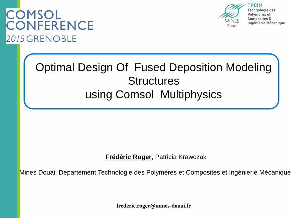
Topological optimisation
Step 1
Optimal infill
Step 2
Optimal design and manufacturing strategy for 3d printing
Reduce weight
Optimal stiffness
Interface resistance
and microstructure
Optimal interface resistance
3d printing Heat
transfer modelling
Step 3
Optimal filaments
adhesion
1
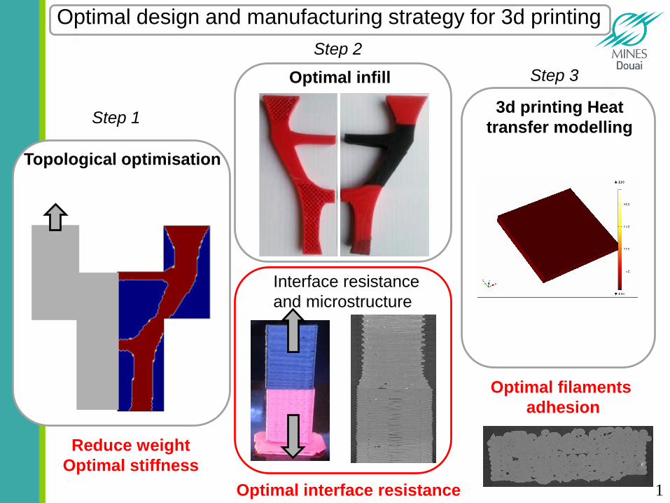
Topological optimization: Solid Isotropic Material with Penalization (Bendsoe 1989)
Objective: Minimise weight and maxime stiffness
minimise
10-9≤rp≤1 et p=5
Maximal surface :
0
1
0 0.5 1
E/E0
Step 1 Optimal outer design : topological optimization
2
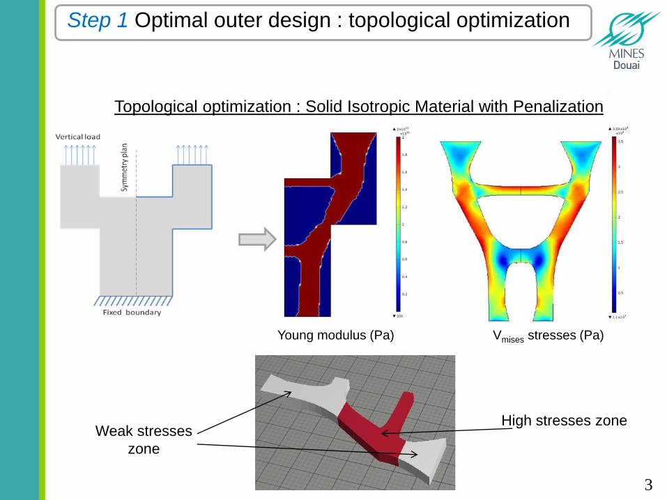
Topological optimization : Solid Isotropic Material with Penalization
Weak stresses
zone
High stresses zone
Young modulus (Pa) Vmises stresses (Pa)
Step 1 Optimal outer design : topological optimization
3

Optimize manufacturing patterns (inner structure)
with outer optimal geometry
Two materials structure Heterogeneous infill structure
?
Step 2 Optimal infill: heterogeneous infill / multi materials
4
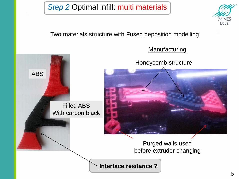
ABS
Filled ABS
With carbon black
Two materials structure with Fused deposition modelling
Interface resitance ?
Manufacturing
Honeycomb structure
Purged walls used
before extruder changing
Step 2 Optimal infill: multi materials
5
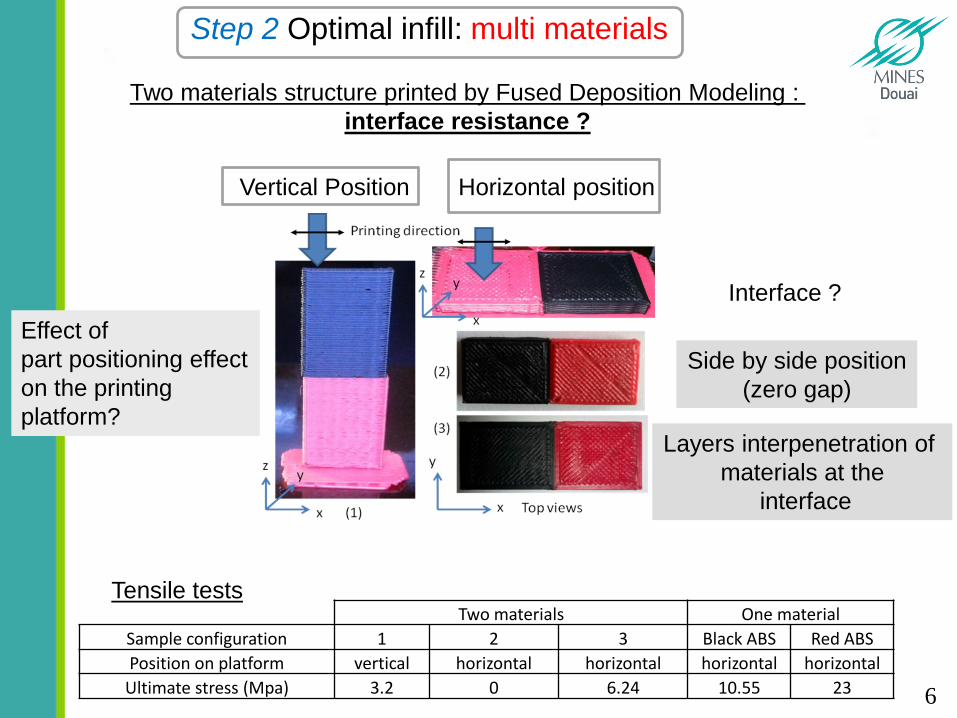
Two materials structure printed by Fused Deposition Modeling :
interface resistance ?
Effect of
part positioning effect
on the printing
platform?
Vertical Position Horizontal position
Side by side position
(zero gap)
Layers interpenetration of
materials at the
interface
Interface ?
Two materials One material
Sample configuration 1 2 3 Black ABS Red ABS
Position on platform vertical horizontal horizontal horizontal horizontal
Ultimate stress (Mpa) 3.2 0 6.24 10.55 23
Tensile tests
Step 2 Optimal infill: multi materials
6
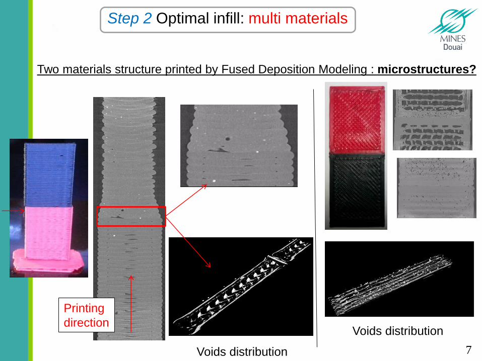
Printing
direction
Two materials structure printed by Fused Deposition Modeling : microstructures?
Step 2 Optimal infill: multi materials
Voids distribution
Voids distribution
7
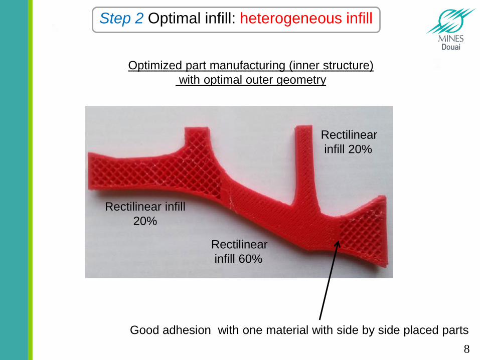
Optimized part manufacturing (inner structure)
with optimal outer geometry
Rectilinear infill
20%
Rectilinear
infill 60%
Rectilinear
infill 20%
Good adhesion with one material with side by side placed parts
Step 2 Optimal infill: heterogeneous infill
8
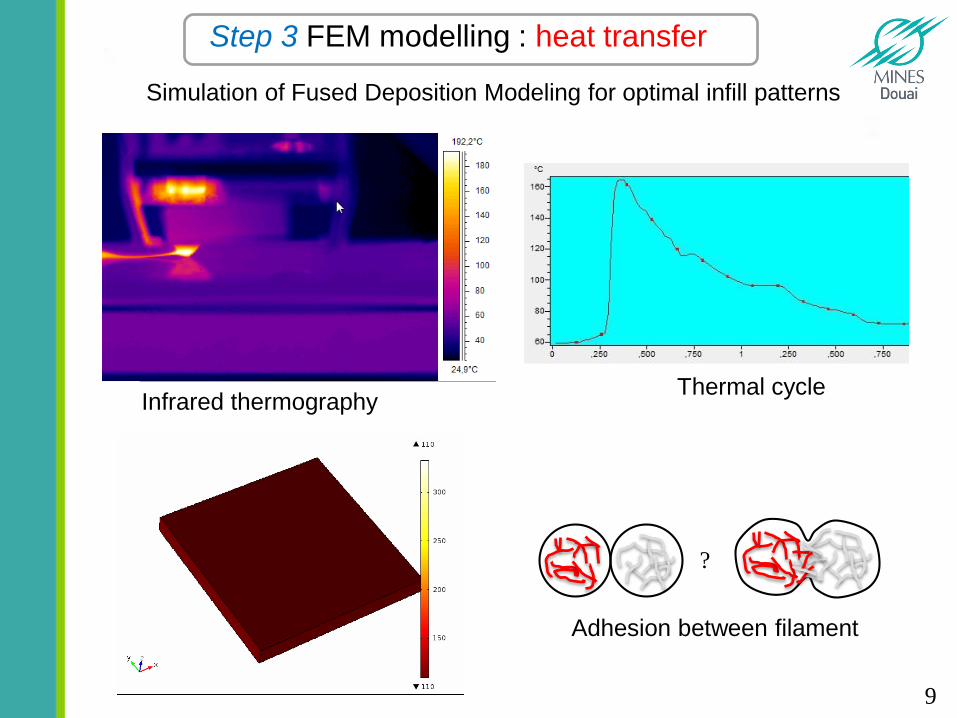
Simulation of Fused Deposition Modeling for optimal infill patterns
Infrared thermography
Step 3 FEM modelling : heat transfer
Thermal cycle
?
Adhesion between filament
9
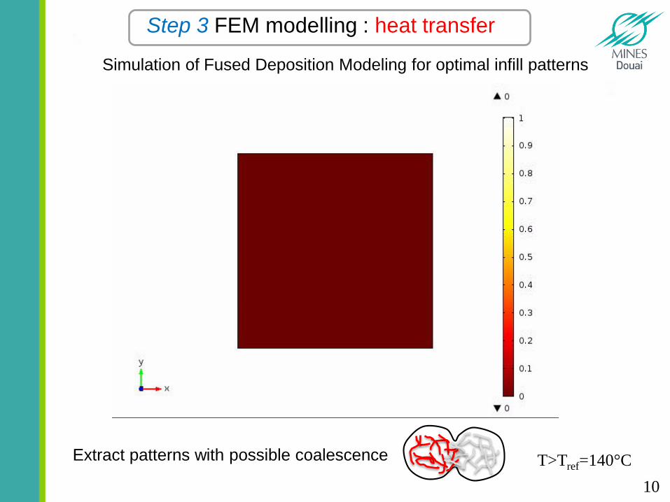
Extract patterns with possible coalescence T>Tref=140°C
Simulation of Fused Deposition Modeling for optimal infill patterns
Step 3 FEM modelling : heat transfer
10
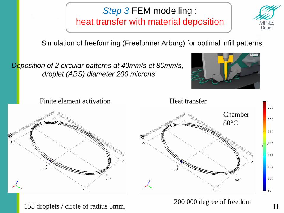
Deposition of 2 circular patterns at 40mm/s et 80mm/s,
droplet (ABS) diameter 200 microns
200 000 degree of freedom155 droplets / circle of radius 5mm,
Finite element activation Heat transfer
Chamber
80°C
Simulation of freeforming (Freeformer Arburg) for optimal infill patterns
Step 3 FEM modelling :
heat transfer with material deposition
11
Conclusion and perpectives:
-Optimal part shape can be obtained by topological optimization
-Optimal Inner structure can improve part resistance :
-Adding a high strength materials in critical areas
-Choosing the right layers orientations
-Increasing infill density in critical areas
-Heat transfer and material deposition modeling can help to find
best infill patterns strategy to maximise filaments adhesion
-Next steps:
-Modeling of filament wetting and adhesion
-Modeling of stresses and strains during and after 3d printing
12
Thank you for your attention
13
Recommended