phys. stat. sol. (c) 4, No. 2, 279–287 (2007) / DOI 10.1002/pssc.200673208
© 2007 WILEY-VCH Verlag GmbH & Co. KGaA, Weinheim
Optical Landau state mapping with in-plane electric fields
Biswajit Karmakar1, 3, Michael Schardt2, Stefan Malzer2, Brij. M. Arora1,
and Gottfried H. Döhler*, 1, 2
1 Tata Institute of Fundamental Research, Homi Bhabha Rd., Mumbai 400005, India 2 Max Planck Research Group, Institute of Optics, Information and Photonics,
University Erlangen-Nürnberg, Günther-Scharowsky-Str. 1, Bau 24, 91058 Erlangen, Germany 3 NEST-INFM, Scuola Normale Superiore, Pisa 56126, Italy
Received 30 July 2006, accepted 18 August 2006
Published online 7 February 2007
PACS 71.70.Di, 73.21.Fg, 78.20.Ls, 78.67.De
We report on a theoretical and experimental investigation of magneto-absorption in quantum wells (QWs)
in the presence of a uniform in-plane electric field. From a simple theoretical model a linear real-space
shift of the electron Landau level wave functions relative to the hole counterparts is expected under in-
creasing in-plane electric field. As a result, quadratic Stark shifts, fading of the zero-field allowed transi-
tions, and increasing oscillator strength for the originally forbidden transitions are predicted. These pre-
dictions are confirmed by experiments on GaAs/AlGaAs-QWs and found to be in reasonably good
agreement with simulations based on a simple model.
© 2007 WILEY-VCH Verlag GmbH & Co. KGaA, Weinheim
1 Introduction Absorption in quantum wells (QWs) with a magnetic field B normal to the QW plane
results from transitions between valence band and conduction band Landau levels. Due to the QW con-
finement in growth direction (taken as the z-coordinate) and the quantization of the in-plane motion by
the magnetic field the conduction and valence band states are fully quantized. The corresponding Landau
state wave functions in the x-y plane correspond to harmonic oscillators whose extent is characterized by
the magnetic length l0 = (ħ/eB)½. As this length scale does not depend on the effective masses of the
carriers, it is the same for conduction and valence band Landau levels. Therefore, based on these simpli-
fied considerations (neither heavy/light-hole valence band mixing nor excitonic effects are included!), a
strict selection rule n = m for interband transitions between hole and electron Landau levels labeled n, m
= 0, 1, 2, …, respectively, normally applies. There have been numerous reports on experiments [1–5] and
(more sophisticated) theoretical [6–8] investigations of this scenario in the literature.
To the best of our knowledge, the interesting case of magneto-absorption in QWs in the presence of
in-plane electric fields has never been investigated. This is surprising because of its relevance to optical
absorption associated with edge states in the quantum Hall regime, where lateral electric fields are also
present [9]. The effect of a lateral electric field is interesting, as it breaks the in-plane symmetry. In fact,
a lateral electric field, F = (F, 0, 0) induces a spatial shift of the center-of-mass of the electron Landau
level wave function relative to the corresponding hole wave functions in x-direction. As we will see
below, this shift is linear in the ratio F/B. With increasing F/B the overlap of corresponding hole and
electron Landau states (n = m), decreases, whereas the originally forbidden transitions (n ≠ m) become
allowed. At the same time a quadratic spectral red shift by ∆E = ½(me+ mh)(F/B)2 occurs, affecting all
the Landau levels with same effective (in-plane!) masses in the same way, independent of n or m. Inter-
* Corresponding author: e-mail: [email protected]
280 B. Karmakar et al.: Optical Landau state mapping with in-plane electric fields
© 2007 WILEY-VCH Verlag GmbH & Co. KGaA, Weinheim www.pss-c.com
estingly, the Stark shift and the changes of the selection rules depend only on the ratio between electric
and magnetic fields and can be calculated analytically. Due to the broadening of the Landau levels the
evolution of the absorption spectra as a function of F at constant B is expected to reflect both the Stark
shift as well as the fading of the originally allowed transitions in favour of the formerly forbidden ones.
It is probably due to the experimental difficulties associated with the generation of (uniform) in-
plane electric fields F that there are no reports on experimental investigations of magneto-absorption in
the presence of lateral fields. In our investigation we have been able to apply a highly uniform in-plane
electric field by using an AlGaAs/GaAs-MQW-structure which was sandwiched between top and bottom
layers of (low-conducting!) “low-temperature-grown GaAs” (LT-GaAs), provided with lateral contacts
separated by 10 and 20 µm. We have observed drastic changes of the photocurrent spectra with increas-
ing electric field which are in qualitative agreement with simple simulations of the absorption spectra in
a single particle picture.
In the following we will first shortly outline the theoretical framework of magneto-absorption in
QWs in the presence of an in-plane electric field and present the results of simulations (Section 2). Sub-
sequently (Section 3) we will discuss the experimental details. Finally (Section 4) we will present the
experimental spectra and compare them with those obtained from our simplifying theory. We will see
that, although the fundamental features of the spectra are reproduced quite well by the present simula-
tions, excitonic effects have to be taken into account to further improve the agreement and that either a
more realistic valence band structure has to be considered, or a sample design with a simpler valence
band structure has to be chosen.
2 Theory
2.1 Eigenstates The Schrödinger equation for an electron with an effective mass mc in a quantum
well is
{1/2mc[(ħ/i) ∇]2 + Ec(z)} ψc,v(r) = Ec,ν(kx,ky) ψc,ν (r). (1)
The wave function of the ν−th conduction subband ψc,ν(r) at (r) = (x, y, z) can be written as a product
ψc,ν(r) = ζc,ν(z)φ(x,y) of the envelope function ζc,ν(z) characterizing the quantized states in growth direc-
tion and the free-electron wave function φ(x,y) = exp{ikxx + ikyy}, describing the in-plane motion with
momentum ħk = ħ(kx,ky). The energy can be expressed as
Ec,ν(kx,ky) = Ec + Ec,ν + (ħ2/2mc)(kx2 + ky
2), (2)
where Ec stands for the conduction band edge energy and Ec,ν for the confinement energy of the ν-th
subband.
With a magnetic field B in z-direction, the in-plane motion also becomes quantized. Using the Lan-
dau gauge for the magnetic potential, A = (0,-Bx, 0), the Schrödinger equation for the in-plane motion
now reads
[-(ħ2/2mc) ∂2/∂x2 + 1/2mc{( ħ/i) ∂/∂y – exB}2]φm,(x,ky) = Ec,m(x,ky)φm,(x,ky). (3)
With the ansatz
φm(x,ky) = χ m(x-xc,0) exp{ikyy} (4)
we obtain the 1-dimensional harmonic oscillator equation
[-(ħ2/2mc) ∂2/∂x2 + (e2B2/2mc)( ħky/eB – x)2] χ m(x–x0(ky)) = Ec,m χ m(x–x0(ky)). (5)
phys. stat. sol. (c) 4, No. 2 (2007) 281
www.pss-c.com © 2007 WILEY-VCH Verlag GmbH & Co. KGaA, Weinheim
The apex position x0(ky) of the parabolic magnetic potential
v(x) = (e2B2/2mc)[x – x0(ky)]2 (6)
and, hence, also the center of mass of the harmonic oscillator wave functions χ m(x–x0(ky))
depend on the momentum of the electron in y-direction, ħky, according to
x0(ky) = ħky/eB = l02ky, (7)
(with the “magnetic length” defined as l0 = (ħ/eB)½). The eigenvalues, the “Landau levels”,
Ec,m = (½ + m) ħωc, m = 0, 1, 2, … (8)
with the cyclotron frequency given by
ωc = eB/mc, (9)
are degenerate with respect to the ky-values.
By the application of an additional in-plane electric field in x-direction F = (F, 0, 0) the degeneracy
regarding x0(ky) is lifted. With the same ansatz as before, the 1-dimensional Schrödinger equation now
reads
[-(ħ2/2mc)∂2/∂x2 + (e2B2/2mc)[x – x0(ky)]
2 + eFx] χ m(x-xc,0(ky;F)) = Ec,m(ky;F) χ m(x-xc,0(ky;F)). (10)
The parabolic shape of the magnetic potential remains unchanged, but its apex is shifted on the x-axis by
∆xc(F) = -mceF/(eB)2 = -eF(ħ/eB)/(mc/ ħeB) = -[eFl0/( ħωc)] l0 (11)
and in energy by
∆Ec(F) = –ħky(F/B) –mc(F/B)2 = – eFl0[l0ky + ½eFl0/(ħωc)] (12)
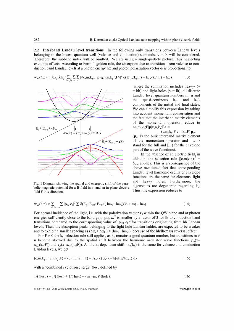
In Fig. 1 the magnetic potential is shown together with the first three Landau levels and envelope
wave functions for B = 8 T and F = 0 (gray lines) and 10 kV/cm (heavy lines).
The analogue calculation can be performed for the heavy and the light holes (labeled hh and lh, re-
spectively, replacing the index c for the electrons). As is well known, the effective masses for the holes
in QWs are highly anisotropic and can be expressed approximately by the Luttinger-parameters γ1 and γ2. The masses responsible for the quantization in growth direction in GaAs are mhh,z = (γ1 – 2γ2)
−1 = 0.38 m0
and mlh,z = (γ1 + 2γ2)−1 = 0.09m0, respectively, whereas for the calculation of the hole Landau levels and
the shift of the wave functions and energies “mass reversal” between heavy and light holes for the in-
plane motion has to be taken into account by using mhh,||� = (γ1 + γ2)−1 = 0.11 m0 and mlh,||�= (γ1– γ2)
−1 =
0.21m0, respectively.
Using these parameters we obtain the spatial and energetic shifts of the valence band states. In Fig. 1 the
results for the (“light”) heavy hole states are depicted for the same fields as for the electrons. Note that
the cyclotron frequencies for the heavy holes, ωhh = eB/mhh,||, are larger than those for the light hole Lan-
dau levels, ωlh = eB/mlh,||. Correspondingly, the spatial and energetic shift is largest for the light-hole
eigenstates.
282 B. Karmakar et al.: Optical Landau state mapping with in-plane electric fields
© 2007 WILEY-VCH Verlag GmbH & Co. KGaA, Weinheim www.pss-c.com
Fig. 1 Diagram showing the spatial and energetic shift of the para-
bolic magnetic potential for a B-field in z- and an in-plane electric
field F in x-direction.
2.2 Interband Landau level transitions In the following only transitions between Landau levels
belonging to the lowest quantum well (valence and conduction) subbands, ν = 0, will be considered.
Therefore, the subband index will be omitted. We are using a single-particle picture, thus neglecting
excitonic effects. According to Fermi’s golden rule, the absorption due to transitions from valence to con-
duction band Landau levels at a photon energy ħω and photon polarization vector e0 is proportional to
wvc(ħω) ∝ ∫dky ∫dky’ ∑ ∑ ∑ |<c,m,ky;F|p⋅e0|v,n,ky’;F>|2 δ(Ec,m(ky;F) – Ev,n(ky’;F) – ħω) (13)
hh,lh m n
where the summation includes heavy- (v
= hh) and light-holes (v = lh), all discrete
Landau level quantum numbers m, n and
the quasi-continous ky- and ky’-
components of the initial and final states.
We can simplify this expression by taking
into account momentum conservation and
the fact that the interband matrix elements
of the momentum operator reduce to
<c,m,ky;F|p|v,n,ky;F> =
(c,m,ky;F|v,n,ky;F) pcv
(pcv is the bulk interband matrix element
of the momentum operator and |… >
stand for the full and |…) for the envelope
part of the wave functions).
In the absence of an electric field, in
addition, the selection rule |(c,m|v,n)|2 =
δm,n applies. This is a consequence of the
above mentioned fact that corresponding
Landau level harmonic oscillator envelope
functions are the same for electrons, light
and heavy holes. Furthermore, the
eigenstates are degenerate regarding ky.
Thus, the expression reduces to
wvc(ħω) ∝ ∑ ∑ |pcv⋅e0|2 ∑ δ(Eg+Ec,0+Ev,0+( ħωc+ ħωv)(½ + m) – ħω) (14)
hh,lh m
For normal incidence of the light, i.e. with the polarization vector e0 within the QW plane and at photon
energies sufficiently close to the band gap, |pclh⋅e0|2 is smaller by a factor of 3 for lh-to conduction band
transitions compared to the corresponding value of |pchh⋅e0|2 for transitions originating from hh Landau
levels. Thus, the absorption peaks belonging to the light hole Landau ladder, are expected to be weaker
and to exhibit a smaller spacing as (ħωc+ ħωlh) < (ħωc+ ħωhh), because of the hh/lh-mass reversal effect.
For F ≠ 0 the ky-selection rule still applies, as ky remains a good quantum number, but transitions m ≠
n become allowed due to the spatial shift between the harmonic oscillator wave functions χm(x–
xc,0(ky;F)) and χn(x–xv,0(ky;F)). As the ky-dependent shift –x0(ky) is the same for valence and conduction
Landau levels, we get
(c,m,ky;F|v,n,ky;F) = (c,m;F|v,n;F) = ∫χm(x) χn(x– l0(eFl0/ħωcv))dx (15)
with a “combined cyclotron energy” ħωcv defined by
1/( ħωcv) = 1/( ħωc) + 1/( ħωv) = (mc+mv)/ (ħeB). (16)
phys. stat. sol. (c) 4, No. 2 (2007) 283
www.pss-c.com © 2007 WILEY-VCH Verlag GmbH & Co. KGaA, Weinheim
The expression for (c,m;F|v,n;F) can also be rewritten in a physically less intuitive, but mathemati-
cally more elegant form as
(c,m;F|v,n;F) = ∫χm(x) χn(x– (mc+mv)(F/B))dx (17)
As the magnetic length is the scaling length of our harmonic oscillator wave functions, Eq. (12) tells us
that deviations from the selection rule m = n become significant if the electric field potential drop per
magnetic length becomes comparable to the combined cyclotron energy.
For the corresponding transition energies also the ky-dependent contributions cancel each other and
we obtain
Ec,0,m(ky,F) – Ev,0,n(ky,F) = Eg+Ec,0+Ev,0+ ħωc(½ + m)+ ħωv(½ + n) – ½eFl0[eFl0/( ħωcv)] (18)
We see that the (quadratic) Stark shift, on the scale of potential drop per magnetic length, eFl0, is given
by the ratio of potential drop over “interband cyclotron energy” ħωcv. Again, this expression can be writ-
ten in a physically less intuitive, but mathematically more elegant form as
Ec,0,m(ky,F) – Ev,0,n(ky,F) = Eg+Ec,0+Ev,0+ ħωc(½ + m)+ ħωv(½ + n) – ½ (mc+mv)(F/B)2 (19)
The absorption strength at these transition energies becomes
wvn,cm(ħω) ∝ |pcv⋅e0|2 |(c,m;F|v,n;F)|2. (20)
Thus the evolution of the intensity due to the mn-Landau level transitions provides a mapping of the
corresponding envelope functions.
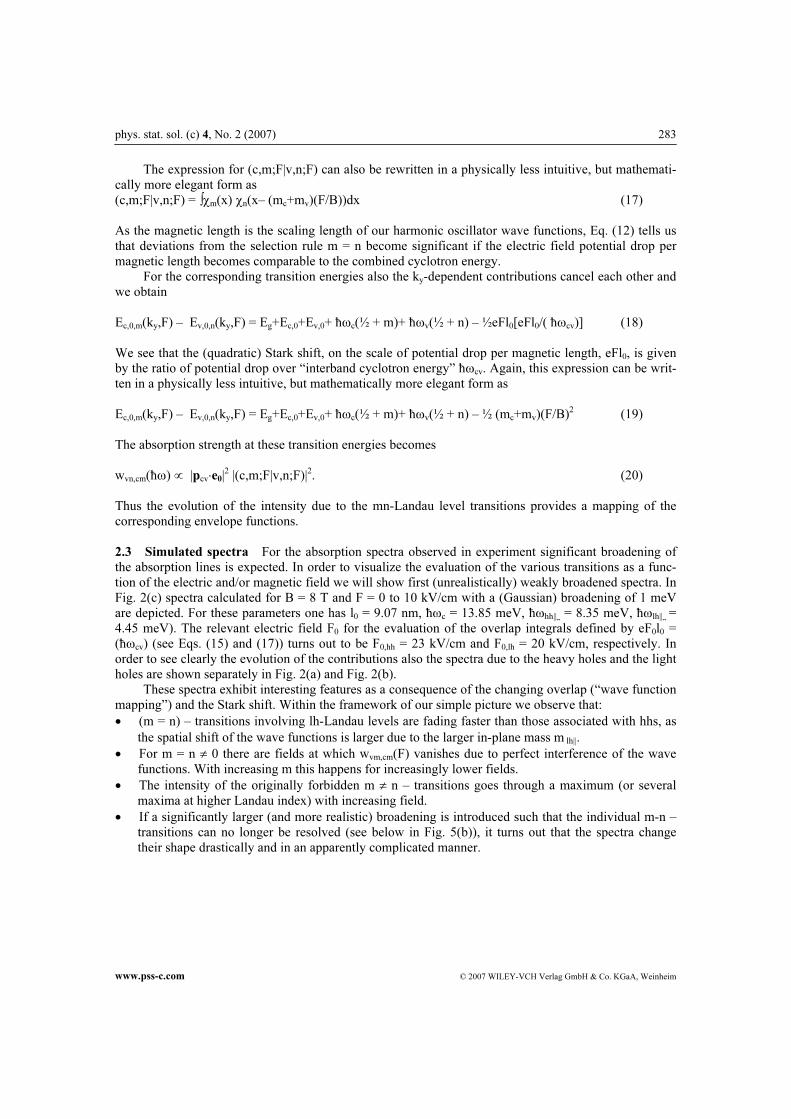
2.3 Simulated spectra For the absorption spectra observed in experiment significant broadening of
the absorption lines is expected. In order to visualize the evaluation of the various transitions as a func-
tion of the electric and/or magnetic field we will show first (unrealistically) weakly broadened spectra. In
Fig. 2(c) spectra calculated for B = 8 T and F = 0 to 10 kV/cm with a (Gaussian) broadening of 1 meV
are depicted. For these parameters one has l0 = 9.07 nm, ħωc = 13.85 meV, ħωhh||� = 8.35 meV, ħωlh||� =
4.45 meV). The relevant electric field F0 for the evaluation of the overlap integrals defined by eF0l0 =
(ħωcv) (see Eqs. (15) and (17)) turns out to be F0,hh = 23 kV/cm and F0,lh = 20 kV/cm, respectively. In
order to see clearly the evolution of the contributions also the spectra due to the heavy holes and the light
holes are shown separately in Fig. 2(a) and Fig. 2(b).
These spectra exhibit interesting features as a consequence of the changing overlap (“wave function
mapping”) and the Stark shift. Within the framework of our simple picture we observe that:
• (m = n) – transitions involving lh-Landau levels are fading faster than those associated with hhs, as
the spatial shift of the wave functions is larger due to the larger in-plane mass m lh||.
• For m = n ≠ 0 there are fields at which wvm,cm(F) vanishes due to perfect interference of the wave
functions. With increasing m this happens for increasingly lower fields.
• The intensity of the originally forbidden m ≠ n – transitions goes through a maximum (or several
maxima at higher Landau index) with increasing field.
• If a significantly larger (and more realistic) broadening is introduced such that the individual m-n –
transitions can no longer be resolved (see below in Fig. 5(b)), it turns out that the spectra change
their shape drastically and in an apparently complicated manner.
284 B. Karmakar et al.: Optical Landau state mapping with in-plane electric fields
© 2007 WILEY-VCH Verlag GmbH & Co. KGaA, Weinheim www.pss-c.com
Fig. 2 Evolution of interband Landau level transitions as a function of electric field (0 to 10 V in steps of 0.5 V,
shifted by a constant for clarity), calculated with a single particle picture and the mass-reversal model for the valence
band states for a) heavy holes, b) light holes, and c)both combined with the hh/lh oscillator strength ratio of 3:1. The
oscillator strength for transitions forbidden at E = 0 (m ≠ n) increases and that of originally allowed m = n – transi-
tion fades faster.The Stark-shift is clearly seen to be more pronounced for light-holes (b) than for the heavy-holes
(a).
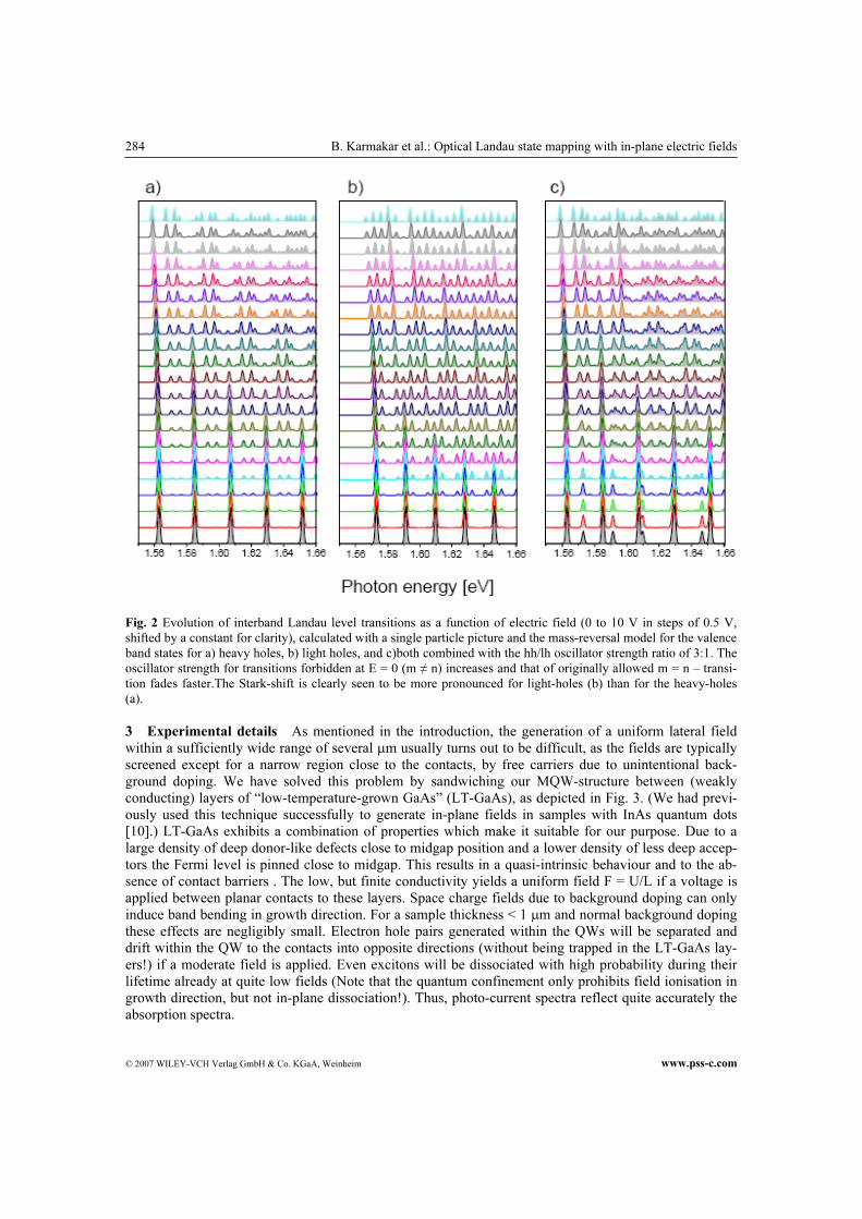
3 Experimental details As mentioned in the introduction, the generation of a uniform lateral field
within a sufficiently wide range of several µm usually turns out to be difficult, as the fields are typically
screened except for a narrow region close to the contacts, by free carriers due to unintentional back-
ground doping. We have solved this problem by sandwiching our MQW-structure between (weakly
conducting) layers of “low-temperature-grown GaAs” (LT-GaAs), as depicted in Fig. 3. (We had previ-
ously used this technique successfully to generate in-plane fields in samples with InAs quantum dots
[10].) LT-GaAs exhibits a combination of properties which make it suitable for our purpose. Due to a
large density of deep donor-like defects close to midgap position and a lower density of less deep accep-
tors the Fermi level is pinned close to midgap. This results in a quasi-intrinsic behaviour and to the ab-
sence of contact barriers . The low, but finite conductivity yields a uniform field F = U/L if a voltage is
applied between planar contacts to these layers. Space charge fields due to background doping can only
induce band bending in growth direction. For a sample thickness < 1 µm and normal background doping
these effects are negligibly small. Electron hole pairs generated within the QWs will be separated and
drift within the QW to the contacts into opposite directions (without being trapped in the LT-GaAs lay-
ers!) if a moderate field is applied. Even excitons will be dissociated with high probability during their
lifetime already at quite low fields (Note that the quantum confinement only prohibits field ionisation in
growth direction, but not in-plane dissociation!). Thus, photo-current spectra reflect quite accurately the
absorption spectra.
phys. stat. sol. (c) 4, No. 2 (2007) 285
www.pss-c.com © 2007 WILEY-VCH Verlag GmbH & Co. KGaA, Weinheim
Fig. 3 Our scheme to generate in-plane electric fields using top
and bottom layers of low-temperature grown GaAs.
The 20-period 12 nm
Al0.2Ga0.8As / 10 nm-GaAs –
MQW-structure with 200 nm
Al0.2Ga0.8As cladding layers,
followed by 200nm LT-GaAs
were grown by MBE and
processed into long, 10 or 20
µm wide mesas and provided
with lateral Au-contacts, using
conventional photolitho-
graphic methods. The
photocurrent experiments were
performed at liquid He
temperature in a super-
insulated cryostat fitted with a
superconducting 8 T magnet.
For the light source, 20 Hz
chopped unpolarised radiation
from a tungsten lamp dispersed
by a 1/8 m CVI monochro-
mator with a band pass of 1.92
nm and a 590 nm long pass order sorting filter was used. Light was carried to the sample, positioned in
the middle of the superconducting solenoid, using a 1 mm diameter quartz fiber. CW light from an LED
was used to reduce the sample resistance at the low temperature so as to enable the ac response measure-
able with a lock-in amplifier. The ac photocurrents were typically in the (sub) nano-Ampere range up to
the highest applied bias voltage of 10V.
4 Results and discussion
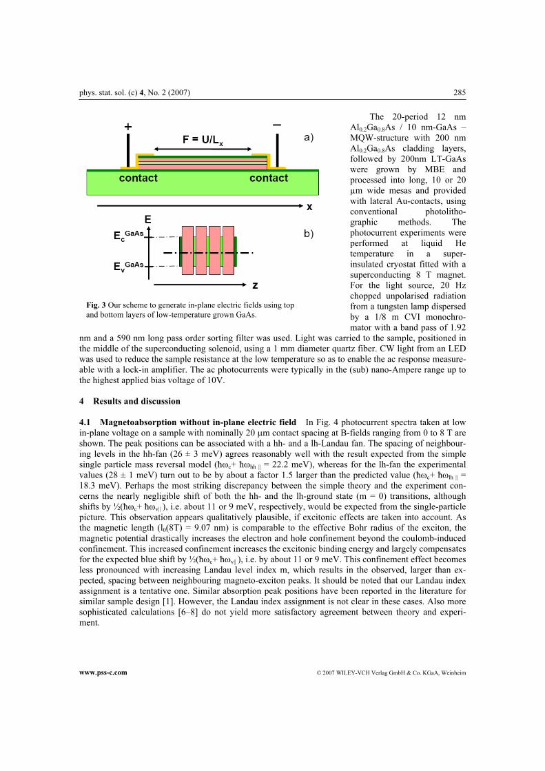
4.1 Magnetoabsorption without in-plane electric field In Fig. 4 photocurrent spectra taken at low
in-plane voltage on a sample with nominally 20 µm contact spacing at B-fields ranging from 0 to 8 T are
shown. The peak positions can be associated with a hh- and a lh-Landau fan. The spacing of neighbour-
ing levels in the hh-fan (26 ± 3 meV) agrees reasonably well with the result expected from the simple
single particle mass reversal model (ħωc+ ħωhh || = 22.2 meV), whereas for the lh-fan the experimental
values (28 ± 1 meV) turn out to be by about a factor 1.5 larger than the predicted value (ħωc+ ħωlh || =
18.3 meV). Perhaps the most striking discrepancy between the simple theory and the experiment con-
cerns the nearly negligible shift of both the hh- and the lh-ground state (m = 0) transitions, although
shifts by ½(ħωc+ ħωv|| ), i.e. about 11 or 9 meV, respectively, would be expected from the single-particle
picture. This observation appears qualitatively plausible, if excitonic effects are taken into account. As
the magnetic length (l0(8T) = 9.07 nm) is comparable to the effective Bohr radius of the exciton, the
magnetic potential drastically increases the electron and hole confinement beyond the coulomb-induced
confinement. This increased confinement increases the excitonic binding energy and largely compensates
for the expected blue shift by ½(ħωc+ ħωv|| ), i.e. by about 11 or 9 meV. This confinement effect becomes
less pronounced with increasing Landau level index m, which results in the observed, larger than ex-
pected, spacing between neighbouring magneto-exciton peaks. It should be noted that our Landau index
assignment is a tentative one. Similar absorption peak positions have been reported in the literature for
similar sample design [1]. However, the Landau index assignment is not clear in these cases. Also more
sophisticated calculations [6–8] do not yield more satisfactory agreement between theory and experi-
ment.
286 B. Karmakar et al.: Optical Landau state mapping with in-plane electric fields
© 2007 WILEY-VCH Verlag GmbH & Co. KGaA, Weinheim www.pss-c.com
Fig. 4 Empirical linear Landau fan to fit the magneto-
absorption spectra at vanishing lateral electric field. The
dotted line depicts the magnetic-field induced shift of the
transition corresponding to the first excited states of the
QW.
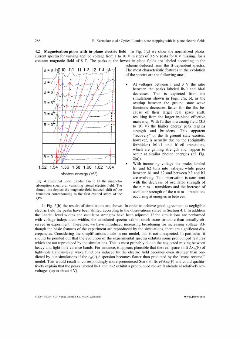
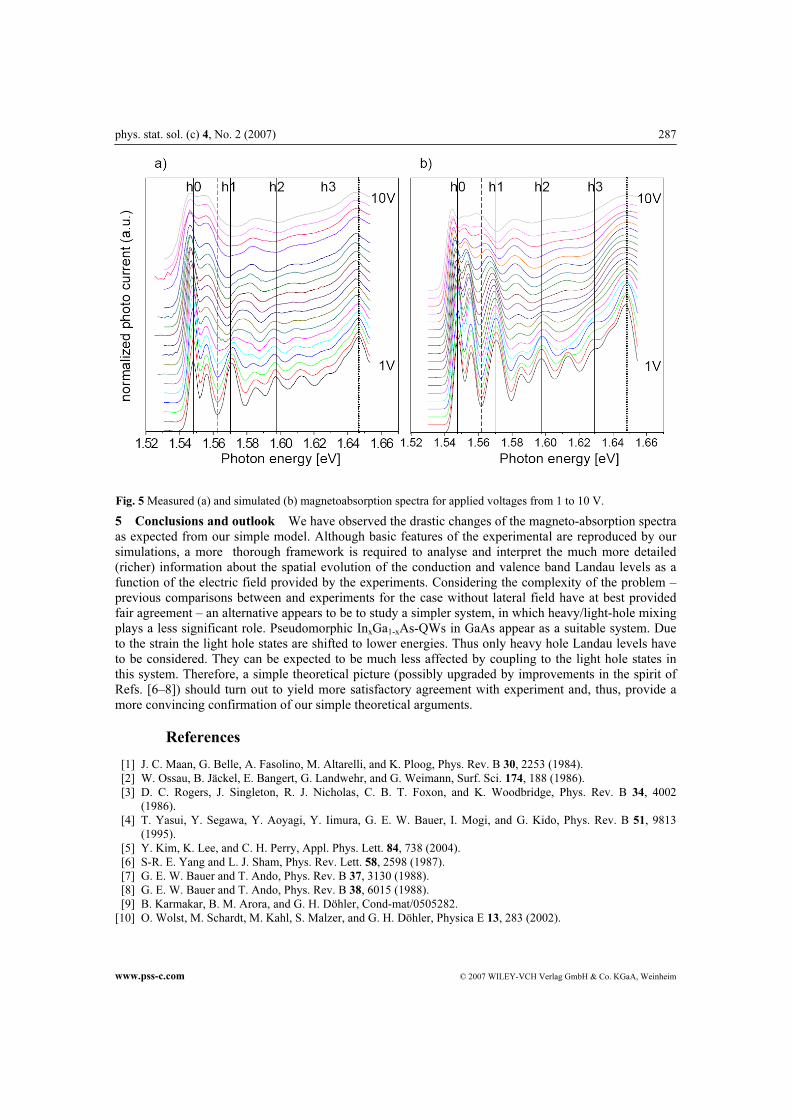
4.2 Magnetoabsorption with in-plane electric field In Fig. 5(a) we show the normalized photo-
current spectra for varying applied voltage from 1 to 10 V in steps of 0.5 V (data for 8 V missing) for a
constant magnetic field of 8 T. The peaks at the lowest in-plane fields are labeled according to the
scheme deduced from the B-dependent spectra.
The most characteristic features in the evolution
of the spectra are the following ones:
• At voltages between 1 and 3 V the ratio
between the peaks labeled lh-0 and hh-0
decreases. This is expected from the
simulations shown in Figs. 2(a, b), as the
overlap between the ground state wave
functions decreases faster for the lhs be-
cause of their larger real space shift,
resulting from the larger in-plane effective
mass mlh||. With further increasing field (3.5
to 10 V) the higher energy peak regains
strength and broadens. This apparent
“recovery” of the lh ground state exciton,
however, is actually due to the (originally
forbidden) h0-e1 and h1-e0 transitions,
which are gaining strength and happen to
occur at similar photon energies (cf. Fig.
2(a)).
• With increasing voltage the peaks labeled
h1 and h2 turn into valleys, while peaks
between h1 and h2 and between h2 and h3
are evolving. This observation is consistent
with the decrease of oscillator strength of
the n = m – transitions and the increase of
oscillator strength of the n ≠ m – transitions
occurring at energies in between.
In Fig. 5(b) the results of simulations are shown. In order to achieve good agreement at negligible
electric field the peaks have been shifted according to the observations stated in Section 4.1. In addition
the Landau level widths and oscillator strengths have been adjusted. If the simulations are performed
with voltage-independent widths, the calculated spectra exhibit much more structure than actually ob-
served in experiment. Therefore, we have introduced increasing broadening for increasing voltage. Al-
though the basic features of the experiment are reproduced by the simulations, there are significant dis-
crepancies. Considering the simplifications made in our model, this is not unexpected. In particular, it
should be pointed out that the evolution of the experimental spectra exhibits some pronounced features
which are not reproduced by the simulations. This is most probably due to the neglected mixing between
heavy and light hole valence bands. For instance, it appears plausible that the real space shift ∆xlh(F) of
light-hole Landau-level wave functions induced by the electric field becomes even stronger than pre-
dicted by our simulations if the εlh(k)-dispersion becomes flatter than predicted by the “mass reversal”
model. This would result in correspondingly more pronounced Stark shifts eF∆xlh(F) and could qualita-
tively explain that the peaks labeled lh-1 and lh-2 exhibit a pronounced red-shift already at relatively low
voltages (up to about 4 V).
phys. stat. sol. (c) 4, No. 2 (2007) 287
www.pss-c.com © 2007 WILEY-VCH Verlag GmbH & Co. KGaA, Weinheim
Fig. 5 Measured (a) and simulated (b) magnetoabsorption spectra for applied voltages from 1 to 10 V.
5 Conclusions and outlook We have observed the drastic changes of the magneto-absorption spectra
as expected from our simple model. Although basic features of the experimental are reproduced by our
simulations, a more thorough framework is required to analyse and interpret the much more detailed
(richer) information about the spatial evolution of the conduction and valence band Landau levels as a
function of the electric field provided by the experiments. Considering the complexity of the problem –
previous comparisons between and experiments for the case without lateral field have at best provided
fair agreement – an alternative appears to be to study a simpler system, in which heavy/light-hole mixing
plays a less significant role. Pseudomorphic InxGa1-xAs-QWs in GaAs appear as a suitable system. Due
to the strain the light hole states are shifted to lower energies. Thus only heavy hole Landau levels have
to be considered. They can be expected to be much less affected by coupling to the light hole states in
this system. Therefore, a simple theoretical picture (possibly upgraded by improvements in the spirit of
Refs. [6–8]) should turn out to yield more satisfactory agreement with experiment and, thus, provide a
more convincing confirmation of our simple theoretical arguments.
References
[1] J. C. Maan, G. Belle, A. Fasolino, M. Altarelli, and K. Ploog, Phys. Rev. B 30, 2253 (1984).
[2] W. Ossau, B. Jäckel, E. Bangert, G. Landwehr, and G. Weimann, Surf. Sci. 174, 188 (1986).
[3] D. C. Rogers, J. Singleton, R. J. Nicholas, C. B. T. Foxon, and K. Woodbridge, Phys. Rev. B 34, 4002
(1986).
[4] T. Yasui, Y. Segawa, Y. Aoyagi, Y. Iimura, G. E. W. Bauer, I. Mogi, and G. Kido, Phys. Rev. B 51, 9813
(1995).
[5] Y. Kim, K. Lee, and C. H. Perry, Appl. Phys. Lett. 84, 738 (2004).
[6] S-R. E. Yang and L. J. Sham, Phys. Rev. Lett. 58, 2598 (1987).
[7] G. E. W. Bauer and T. Ando, Phys. Rev. B 37, 3130 (1988).
[8] G. E. W. Bauer and T. Ando, Phys. Rev. B 38, 6015 (1988).
[9] B. Karmakar, B. M. Arora, and G. H. Döhler, Cond-mat/0505282.
[10] O. Wolst, M. Schardt, M. Kahl, S. Malzer, and G. H. Döhler, Physica E 13, 283 (2002).
Recommended