OPERATION AND
INSTALLATION
GUIDE
FOR MODELS:
SPS-120 & SPP-180
GILLETTE GENERATORS
AUTOMATIC POWER SYSTEMS
PAGE 2
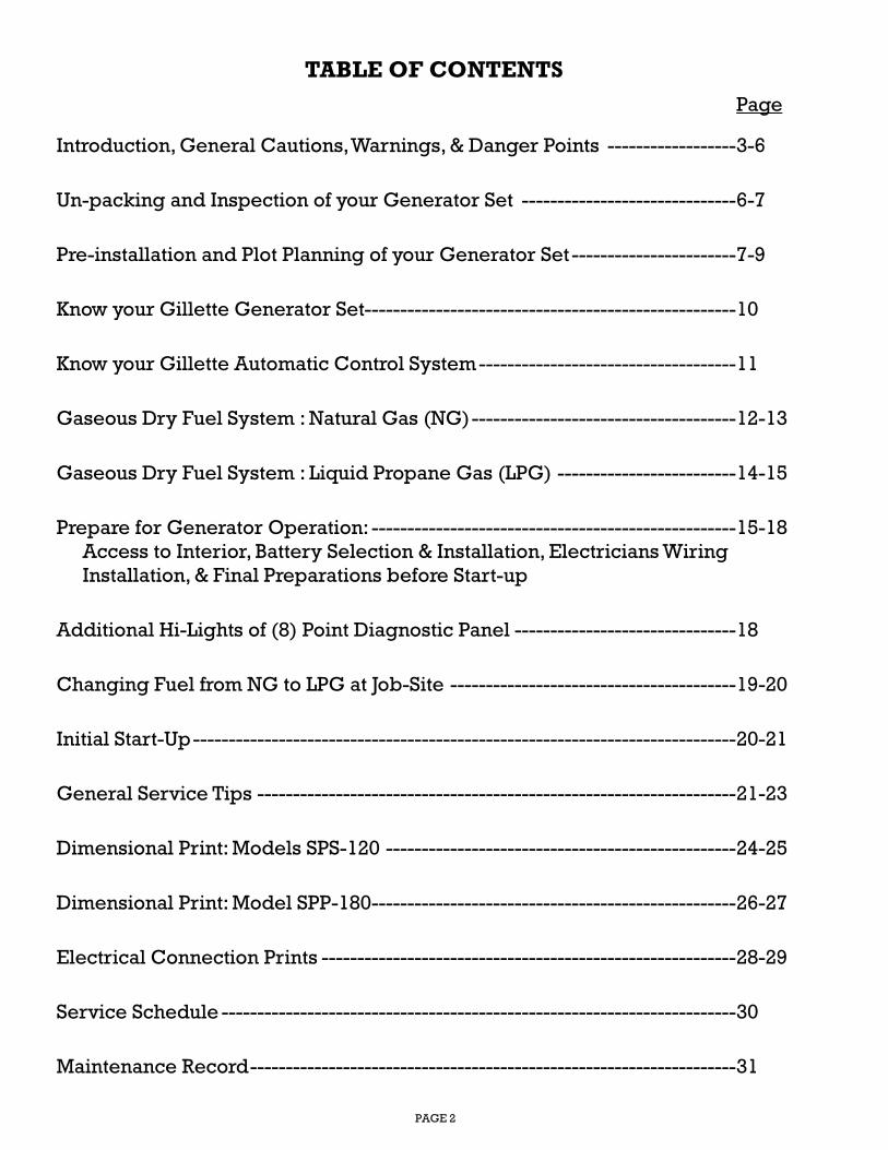
TABLE OF CONTENTS
Page
Introduction, General Cautions, Warnings, & Danger Points ------------------ 3-6
Un-packing and Inspection of your Generator Set ------------------------------ 6-7
Pre-installation and Plot Planning of your Generator Set ----------------------- 7-9
Know your Gillette Generator Set---------------------------------------------------- 10
Know your Gillette Automatic Control System ------------------------------------ 11
Gaseous Dry Fuel System : Natural Gas (NG) ------------------------------------- 12-13
Gaseous Dry Fuel System : Liquid Propane Gas (LPG) ------------------------- 14-15
Prepare for Generator Operation: --------------------------------------------------- 15-18
Access to Interior, Battery Selection & Installation, Electricians Wiring
Installation, & Final Preparations before Start-up
Additional Hi-Lights of (8) Point Diagnostic Panel ------------------------------- 18
Changing Fuel from NG to LPG at Job-Site ---------------------------------------- 19-20
Initial Start-Up ---------------------------------------------------------------------------- 20-21
General Service Tips ------------------------------------------------------------------- 21-23
Dimensional Print: Models SPS-120 ------------------------------------------------- 24-25
Dimensional Print: Model SPP-180--------------------------------------------------- 26-27
Electrical Connection Prints ---------------------------------------------------------- 28-29
Service Schedule ------------------------------------------------------------------------ 30
Maintenance Record -------------------------------------------------------------------- 31
PAGE 3
THIS MANUAL CONTAINS IMPORTANT
INSTRUCTIONS THAT MUST BE FOLLOWED
DURING INSTALLATION, OPERATION, AND
MAINTENANCE OF THIS GENERATOR SET AND
ALL ASSOCIATED EQUIPMENT.
Thoroughly read this operators manual before
installing, operating, or servicing your generator set.
Safe operation and best performance can be
achieved only when this generator is operated and
maintained properly.
INTRODUCTION
Thank you for your purchase of this SENTRY-PRO
automatic start/stop home standby generator set by
GILLETTE GENERATORS, INC. This generator set is
intended for use as an alternative source of electric
power to operate normally required household
electric loads, during a utility power failure.
This generator set has an all weather protected metal
enclosure, MADE EXCLUSIVELY FOR OUTDOOR
INSTALLATION, and will operate on either vapor
withdrawal liquid propane gas (LPG) or natural gas
(NG). CAUTION: This generator does not comply
with emergency power as defined in NFPA 70 of
National Electric Code.
GILLETTE GENERATORS has made every effort to
present a modern, safe generator set that will give
you a safe, clean supply of an alternative source.
However, because each installation is different, it is
impossible for this manual and GILLETTE to know and
advise against all possible hazards. The listings,
warnings, and cautions in this manual and on tags and
decals affixed to the generator set, are therefore,
NOT ALL INCLUSIVE. If a certain procedure, work
method, test method, or operating procedure is used,
and is not recommended by GILLETTE, the person or
company responsible for the generator modification,
must assume all responsibility for safety and correct
operation for the operator, service technician, and all
others within generator area.
READ YOUR GENERATOR SET MANUAL, PLUS
SEPARATE ENGINE OPERATORS MANUAL AND
AUTOMATIC TRANSFER SWITCH MANUAL
CAREFULLY. KNOW YOUR EQUIPMENT
BEFORE YOU USE IT. CONSIDER ANY POSSIBLE,
POTENTIAL HAZARDS, BEFORE OPERATING YOUR GENERATOR SET.
CAUTION: Only current licensed electrical and
plumbing contractors should install your home
standby generator. All phase of installation must
comply with all applicable local and national codes,
industry standards, and regulations.
THE GILLETTE WARRANTY IS AUTOMATICALLY
NULL AND VOID WITHOUT THE USE OF
LICENSED ELECTRICIANS AND PLUMBERS, AND
SO NOTED ON THE REGISTRATION FORM THAT
IS TO BE RETURNED TO GILLETTE GENERATORS, INC.
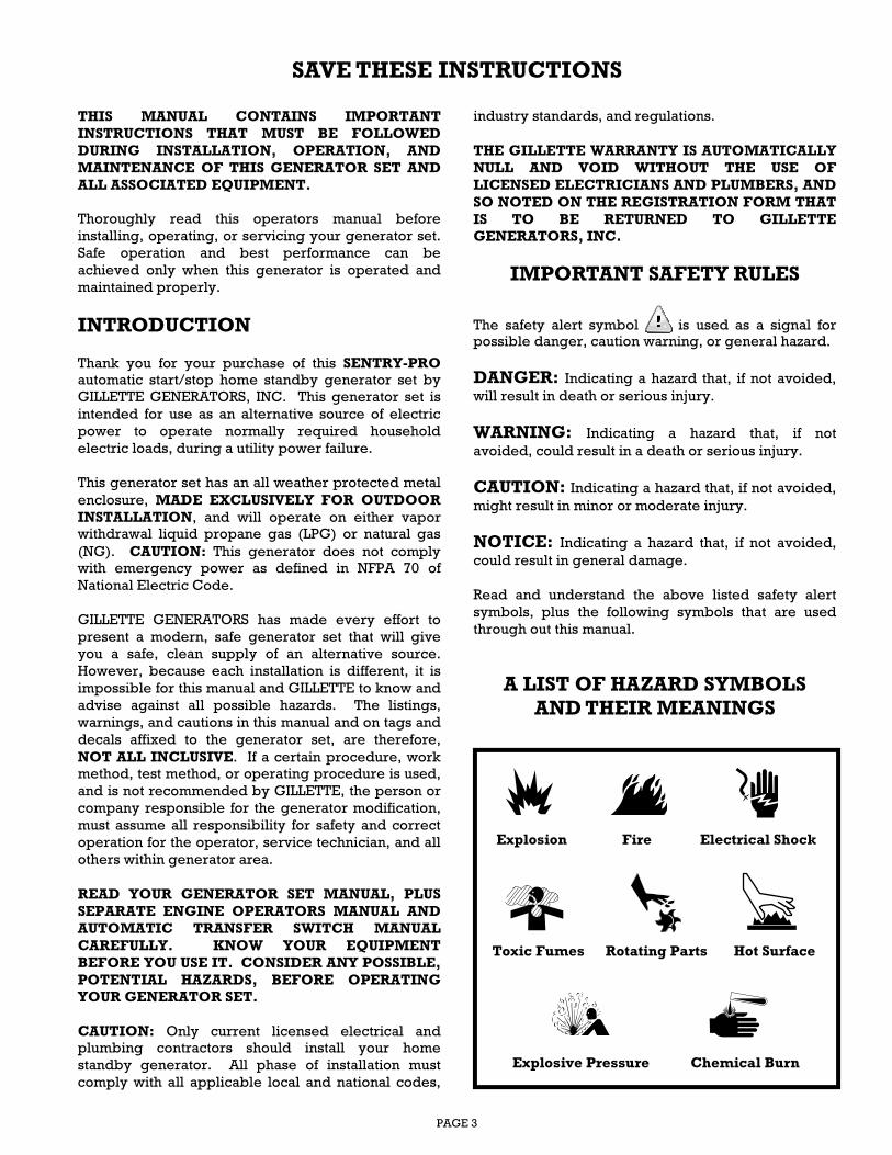
IMPORTANT SAFETY RULES
The safety alert symbol is used as a signal for possible danger, caution warning, or general hazard.
DANGER: Indicating a hazard that, if not avoided,
will result in death or serious injury.
WARNING: Indicating a hazard that, if not
avoided, could result in a death or serious injury.
CAUTION: Indicating a hazard that, if not avoided,
might result in minor or moderate injury.
NOTICE: Indicating a hazard that, if not avoided,
could result in general damage.
Read and understand the above listed safety alert
symbols, plus the following symbols that are used
through out this manual.
A LIST OF HAZARD SYMBOLS AND THEIR MEANINGS
SAVE THESE INSTRUCTIONS
Explosion
Toxic Fumes
Fire
Chemical Burn Explosive Pressure
Rotating Parts Hot Surface
Electrical Shock
PAGE 4
NOTICE
● For all safety reasons to the equipment, GILLETTE
recommends installation, start-up and service be
performed by experienced personnel.
● Sufficient, un-obstructed flow of cooling air is
critical for correct generator operation.
● The generator must be installed outdoors, away
from an over-hang roof where ice and snow could
avalanche onto generator and away from sprinklers
that could throw water up into cooling vents of
generator.
● Electric load applied to generator should be no
more that 75% of generator maximum rating to avoid
constant maximum generator load use.
● Generator should not be exposed to excessive and
constant moisture, dust, dirt, or corrosive
environments.
● If connected loads cause over heating or excessive
vibration, an overload condition exists. Remove
loads until condition stabilizes.
● Do not sit, step, or load heavy items on generator
roof. Added stress can cause breakage.
● Do not start generator with air cleaner, air cleaner
cover, or oil dipstick removed, nor with oil drain hose
in open drain position.
● Keep a fire extinguisher rated “ABC” close by your
generator and be familiar on how to use it. Consult
your local fire department, for additional fire
prevention ideas.
● Be sure that a positive manual fuel valve be
installed in fuel line feeding generator.
● Do not tamper with engine controls, generator is
factory adjusted to supply rated voltage and speed.
● Never operate generator when ambient
temperature is over 105º F, as electrical insulation
system may fail.
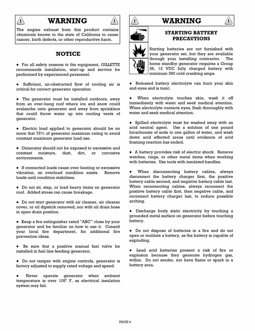
STARTING BATTERY
PRECAUTIONS
Starting batteries are not furnished with
your generator set, but they are available
through your installing contractor. The
home standby generator requires a Group
36, 12 VDC fully charged battery with
minimum 390 cold cranking amps.
● Released battery electrolyte can burn your skin
and eyes and is toxic.
● When electrolyte touches skin, wash it off
immediately with water and seek medical attention.
When electrolyte contacts eyes, flush thoroughly with
water and seek medical attention.
● Spilled electrolyte must be washed away with an
acid neutral agent. Use a solution of one pound
bicarbonate of soda to one gallon of water, and wash
down acid effected areas until evidence of acid
foaming reaction has ended.
● A battery provides risk of electric shock. Remove
watches, rings, or other metal items when working
with batteries. Use tools with insulated handles.
● When disconnecting battery cables, always
disconnect the battery charger first, the positive
battery cable second, and negative battery cable last.
When reconnecting cables, always reconnect the
positive battery cable first, then negative cable, and
reconnect battery charger last, to reduce possible
arching.
● Discharge body static electricity by touching a
grounded metal surface on generator before touching
battery.
● Do not dispose of batteries in a fire and do not
open or mutilate a battery, as the battery is capable of
exploding.
● Lead acid batteries present a risk of fire or
explosion because they generate hydrogen gas,
within. Do not smoke, nor have flame or spark in a
battery area.
WARNING
The engine exhaust from this product contains
chemicals known to the state of California to cause
cancer, birth defects, or other reproductive harm.
WARNING
PAGE 5
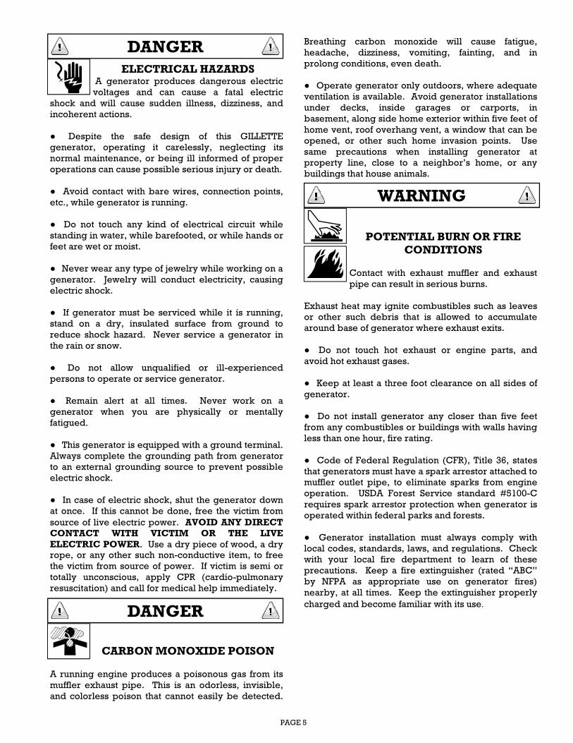
ELECTRICAL HAZARDS A generator produces dangerous electric
voltages and can cause a fatal electric
shock and will cause sudden illness, dizziness, and
incoherent actions.
● Despite the safe design of this GILLETTE
generator, operating it carelessly, neglecting its
normal maintenance, or being ill informed of proper
operations can cause possible serious injury or death.
● Avoid contact with bare wires, connection points,
etc., while generator is running.
● Do not touch any kind of electrical circuit while
standing in water, while barefooted, or while hands or
feet are wet or moist.
● Never wear any type of jewelry while working on a
generator. Jewelry will conduct electricity, causing
electric shock.
● If generator must be serviced while it is running,
stand on a dry, insulated surface from ground to
reduce shock hazard. Never service a generator in
the rain or snow.
● Do not allow unqualified or ill-experienced
persons to operate or service generator.
● Remain alert at all times. Never work on a
generator when you are physically or mentally
fatigued.
● This generator is equipped with a ground terminal.
Always complete the grounding path from generator
to an external grounding source to prevent possible
electric shock.
● In case of electric shock, shut the generator down
at once. If this cannot be done, free the victim from
source of live electric power. AVOID ANY DIRECT CONTACT WITH VICTIM OR THE LIVE
ELECTRIC POWER. Use a dry piece of wood, a dry
rope, or any other such non-conductive item, to free
the victim from source of power. If victim is semi or
totally unconscious, apply CPR (cardio-pulmonary
resuscitation) and call for medical help immediately.
CARBON MONOXIDE POISON
A running engine produces a poisonous gas from its
muffler exhaust pipe. This is an odorless, invisible,
and colorless poison that cannot easily be detected.
Breathing carbon monoxide will cause fatigue,
headache, dizziness, vomiting, fainting, and in
prolong conditions, even death.
● Operate generator only outdoors, where adequate
ventilation is available. Avoid generator installations
under decks, inside garages or carports, in
basement, along side home exterior within five feet of
home vent, roof overhang vent, a window that can be
opened, or other such home invasion points. Use
same precautions when installing generator at
property line, close to a neighbor’s home, or any
buildings that house animals.
POTENTIAL BURN OR FIRE CONDITIONS
Contact with exhaust muffler and exhaust
pipe can result in serious burns.
Exhaust heat may ignite combustibles such as leaves
or other such debris that is allowed to accumulate
around base of generator where exhaust exits.
● Do not touch hot exhaust or engine parts, and
avoid hot exhaust gases.
● Keep at least a three foot clearance on all sides of
generator.
● Do not install generator any closer than five feet
from any combustibles or buildings with walls having
less than one hour, fire rating.
● Code of Federal Regulation (CFR), Title 36, states
that generators must have a spark arrestor attached to
muffler outlet pipe, to eliminate sparks from engine
operation. USDA Forest Service standard #5100-C
requires spark arrestor protection when generator is
operated within federal parks and forests.
● Generator installation must always comply with
local codes, standards, laws, and regulations. Check
with your local fire department to learn of these
precautions. Keep a fire extinguisher (rated “ABC”
by NFPA as appropriate use on generator fires)
nearby, at all times. Keep the extinguisher properly
charged and become familiar with its use.
DANGER
DANGER
WARNING
PAGE 6
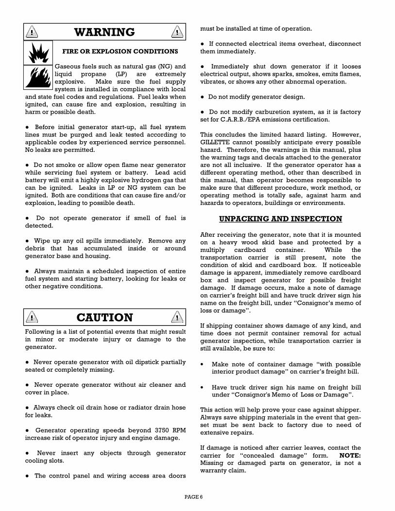
FIRE OR EXPLOSION CONDITIONS
Gaseous fuels such as natural gas (NG) and
liquid propane (LP) are extremely
explosive. Make sure the fuel supply
system is installed in compliance with local
and state fuel codes and regulations. Fuel leaks when
ignited, can cause fire and explosion, resulting in
harm or possible death.
● Before initial generator start-up, all fuel system
lines must be purged and leak tested according to
applicable codes by experienced service personnel.
No leaks are permitted.
● Do not smoke or allow open flame near generator
while servicing fuel system or battery. Lead acid
battery will emit a highly explosive hydrogen gas that
can be ignited. Leaks in LP or NG system can be
ignited. Both are conditions that can cause fire and/or
explosion, leading to possible death.
● Do not operate generator if smell of fuel is
detected.
● Wipe up any oil spills immediately. Remove any
debris that has accumulated inside or around
generator base and housing.
● Always maintain a scheduled inspection of entire
fuel system and starting battery, looking for leaks or
other negative conditions.
Following is a list of potential events that might result
in minor or moderate injury or damage to the
generator.
● Never operate generator with oil dipstick partially
seated or completely missing.
● Never operate generator without air cleaner and
cover in place.
● Always check oil drain hose or radiator drain hose
for leaks.
● Generator operating speeds beyond 3750 RPM
increase risk of operator injury and engine damage.
● Never insert any objects through generator
cooling slots.
● The control panel and wiring access area doors
must be installed at time of operation.
● If connected electrical items overheat, disconnect
them immediately.
● Immediately shut down generator if it looses
electrical output, shows sparks, smokes, emits flames,
vibrates, or shows any other abnormal operation.
● Do not modify generator design.
● Do not modify carburetion system, as it is factory
set for C.A.R.B./EPA emissions certification.
This concludes the limited hazard listing. However,
GILLETTE cannot possibly anticipate every possible
hazard. Therefore, the warnings in this manual, plus
the warning tags and decals attached to the generator
are not all inclusive. If the generator operator has a
different operating method, other than described in
this manual, than operator becomes responsible to
make sure that different procedure, work method, or
operating method is totally safe, against harm and
hazards to operators, buildings or environments.
UNPACKING AND INSPECTION
After receiving the generator, note that it is mounted
on a heavy wood skid base and protected by a
multiply cardboard container. While the
transportation carrier is still present, note the
condition of skid and cardboard box. If noticeable
damage is apparent, immediately remove cardboard
box and inspect generator for possible freight
damage. If damage occurs, make a note of damage
on carrier’s freight bill and have truck driver sign his
name on the freight bill, under “Consignor’s memo of
loss or damage”.
If shipping container shows damage of any kind, and
time does not permit container removal for actual
generator inspection, while transportation carrier is
still available, be sure to:
• Make note of container damage “with possible interior product damage” on carrier’s freight bill.
• Have truck driver sign his name on freight bill under “Consignor's Memo of Loss or Damage”.
This action will help prove your case against shipper.
Always save shipping materials in the event that gen-
set must be sent back to factory due to need of
extensive repairs.
If damage is noticed after carrier leaves, contact the
carrier for “concealed damage” form. NOTE: Missing or damaged parts on generator, is not a
warranty claim.
WARNING
CAUTION
PAGE 7
GENERATOR CONTENTS
The GILLETTE home generator set is supplied with
the following components:
● Home generator system within soundproofed all
weather metal enclosure (Depending on option
choice, this can be an open set or a super-silent
enclosure add).
● Residential muffler system for quiet operation.
● Choice of (3) gen-set mounting systems:
A) Base direct mounting to concrete slab.
B) Base direct mounting to crushed gravel base,
secured in ground with ground stakes.
C) Base with plastic pad for floating mount on
crushed gravel.
● 3/4” NPT female coupling for gas connection.
● Four lifting holes with cover plugs.
● Two locking door keys (NOTE: One key fits all
locks.)
● One spare 20 amp fuse. (Located just above fuse
holder in control panel wiring area)
● Diagnostic LED panel.
● One owner/operator panel.
NOTE: All accessory items will be pre-mounted and
wired to generator. If separate automatic transfer
switch (ATS) is ordered, it is placed on top of
generator shipping box and steel banded in place.
AUTOMATIC TRANSFER SWITCH (ATS)
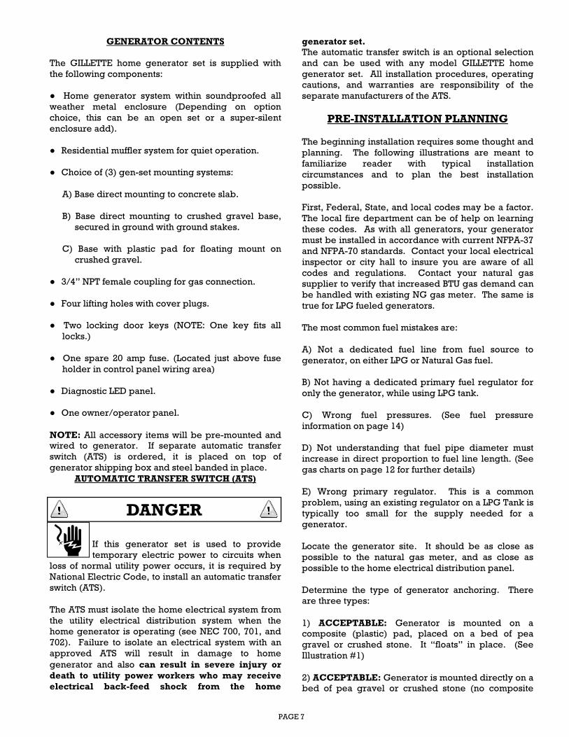
If this generator set is used to provide
temporary electric power to circuits when
loss of normal utility power occurs, it is required by
National Electric Code, to install an automatic transfer
switch (ATS).
The ATS must isolate the home electrical system from
the utility electrical distribution system when the
home generator is operating (see NEC 700, 701, and
702). Failure to isolate an electrical system with an
approved ATS will result in damage to home
generator and also can result in severe injury or
death to utility power workers who may receive
electrical back-feed shock from the home
generator set. The automatic transfer switch is an optional selection
and can be used with any model GILLETTE home
generator set. All installation procedures, operating
cautions, and warranties are responsibility of the
separate manufacturers of the ATS.
PRE-INSTALLATION PLANNING
The beginning installation requires some thought and
planning. The following illustrations are meant to
familiarize reader with typical installation
circumstances and to plan the best installation
possible.
First, Federal, State, and local codes may be a factor.
The local fire department can be of help on learning
these codes. As with all generators, your generator
must be installed in accordance with current NFPA-37
and NFPA-70 standards. Contact your local electrical
inspector or city hall to insure you are aware of all
codes and regulations. Contact your natural gas
supplier to verify that increased BTU gas demand can
be handled with existing NG gas meter. The same is
true for LPG fueled generators.
The most common fuel mistakes are:
A) Not a dedicated fuel line from fuel source to
generator, on either LPG or Natural Gas fuel.
B) Not having a dedicated primary fuel regulator for
only the generator, while using LPG tank.
C) Wrong fuel pressures. (See fuel pressure
information on page 14)
D) Not understanding that fuel pipe diameter must
increase in direct proportion to fuel line length. (See
gas charts on page 12 for further details)
E) Wrong primary regulator. This is a common
problem, using an existing regulator on a LPG Tank is
typically too small for the supply needed for a
generator.
Locate the generator site. It should be as close as
possible to the natural gas meter, and as close as
possible to the home electrical distribution panel.
Determine the type of generator anchoring. There
are three types:
1) ACCEPTABLE: Generator is mounted on a
composite (plastic) pad, placed on a bed of pea
gravel or crushed stone. It “floats” in place. (See
Illustration #1)
2) ACCEPTABLE: Generator is mounted directly on a
bed of pea gravel or crushed stone (no composite
DANGER
PAGE 8
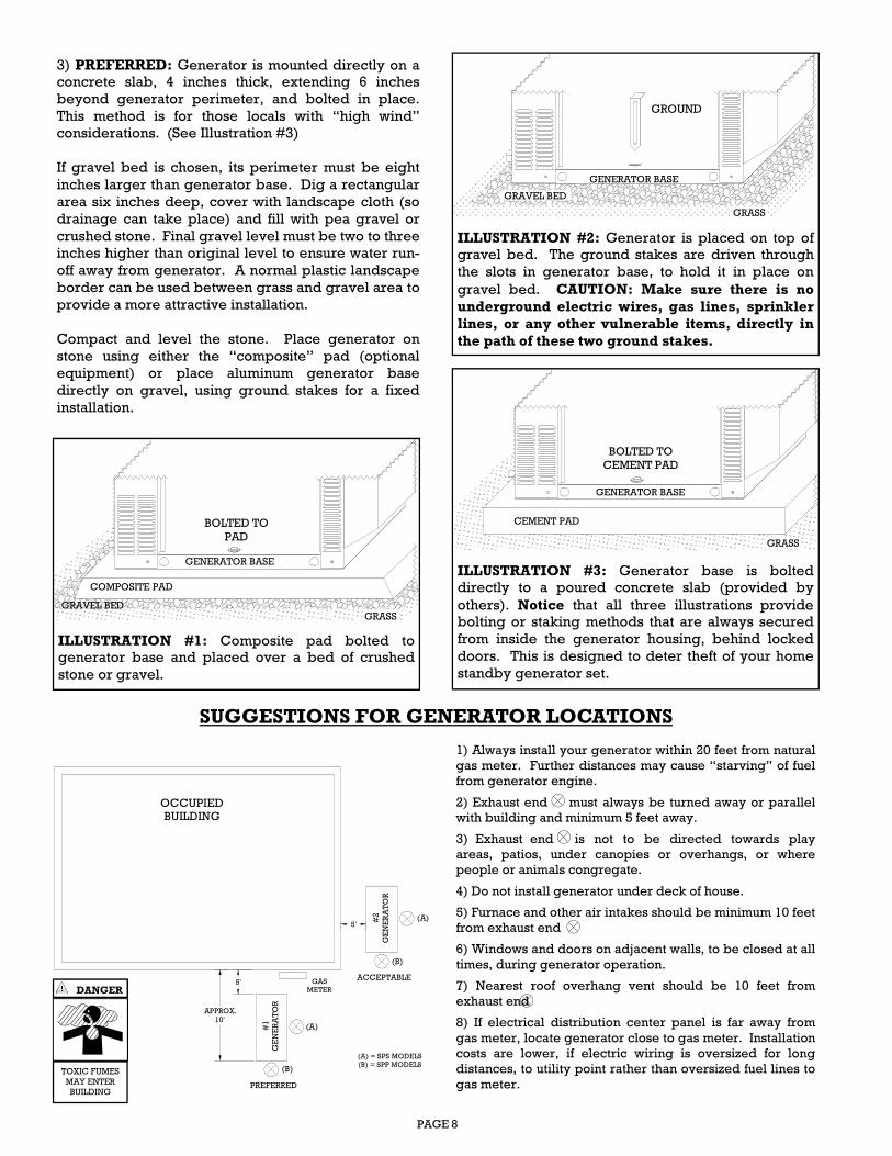
3) PREFERRED: Generator is mounted directly on a
concrete slab, 4 inches thick, extending 6 inches
beyond generator perimeter, and bolted in place.
This method is for those locals with “high wind”
considerations. (See Illustration #3)
If gravel bed is chosen, its perimeter must be eight
inches larger than generator base. Dig a rectangular
area six inches deep, cover with landscape cloth (so
drainage can take place) and fill with pea gravel or
crushed stone. Final gravel level must be two to three
inches higher than original level to ensure water run-
off away from generator. A normal plastic landscape
border can be used between grass and gravel area to
provide a more attractive installation.
Compact and level the stone. Place generator on
stone using either the “composite” pad (optional
equipment) or place aluminum generator base
directly on gravel, using ground stakes for a fixed
installation.
1) Always install your generator within 20 feet from natural
gas meter. Further distances may cause “starving” of fuel
from generator engine.
2) Exhaust end must always be turned away or parallel
with building and minimum 5 feet away.
3) Exhaust end is not to be directed towards play
areas, patios, under canopies or overhangs, or where
people or animals congregate.
4) Do not install generator under deck of house.
5) Furnace and other air intakes should be minimum 10 feet
from exhaust end
6) Windows and doors on adjacent walls, to be closed at all
times, during generator operation.
7) Nearest roof overhang vent should be 10 feet from
exhaust end
8) If electrical distribution center panel is far away from
gas meter, locate generator close to gas meter. Installation
costs are lower, if electric wiring is oversized for long
distances, to utility point rather than oversized fuel lines to
gas meter.
SUGGESTIONS FOR GENERATOR LOCATIONS
5'
5'
APPROX.
10'
OCCUPIEDBUILDING
PREFERRED
ACCEPTABLE
#1
GE
NE
RA
TO
R
#2
GE
NE
RA
TO
R
GAS
METER
(A)
(B)
(A)
(B)
(A) = SPS MODELS
(B) = SPP MODELS
DANGER
TOXIC FUMES
MAY ENTER
BUILDING
ILLUSTRATION #2: Generator is placed on top of
gravel bed. The ground stakes are driven through
the slots in generator base, to hold it in place on
gravel bed. CAUTION: Make sure there is no
underground electric wires, gas lines, sprinkler
lines, or any other vulnerable items, directly in
the path of these two ground stakes.
GROUND
GENERATOR BASE
ILLUSTRATION #1: Composite pad bolted to
generator base and placed over a bed of crushed
stone or gravel.
BOLTED TO
PAD
GENERATOR BASE
GRAVEL BED
COMPOSITE PAD
ILLUSTRATION #3: Generator base is bolted
directly to a poured concrete slab (provided by
others). Notice that all three illustrations provide
bolting or staking methods that are always secured
from inside the generator housing, behind locked
doors. This is designed to deter theft of your home
standby generator set.
GRASS
GRAVEL BED
GRASS
GRASS
BOLTED TO
CEMENT PAD
GENERATOR BASE
CEMENT PAD
PAGE 9
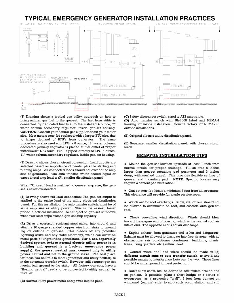
(1) Drawing shows a typical gas utility approach on how to
bring natural gas fuel to the gen-set. The fuel from utility is
connected by dedicated fuel line, to the installed 4 ounce, 7”
water column secondary regulator, inside gen-set housing.
CAUTION: Consult your natural gas supplier about your meter
size. Most meters must be replaced with a larger BTU size, due
to larger demand of BTU’s from generator. The same
procedure is also used with LPG: a 6 ounce, 11” water column,
dedicated primary regulator is placed at fuel outlet of “vapor
withdrawal” LPG tank. Fuel is piped directly to LPG 6 ounce,
11” water column secondary regulator, inside gen-set housing.
(2) Drawing shows chosen circuit connection: Load circuits are
selected based on importance of needs, plus the starting and
running amps. All connected loads should not exceed the amp
size of generator. The auto transfer switch should equal or
exceed total amp load of (F), smaller distribution panel.
When “Chosen” load is matched to gen-set amp size, the gen-
set is never overloaded.
(3) Drawing shows full load connection: The gen-set output is
applied to the entire load of the utility electrical distribution
panel. For this installation, the auto transfer switch, must be of
same amp size as utility power. This is the easiest, lower
priced electrical installation, but subject to gen-set shutdown
whenever load amps exceed gen-set amp capacity.
(A) Drive a corrosion resistant steel stake, into ground and
attach a 10 gauge stranded copper wire from stake to ground
lug on outside of gen-set. This bleeds off any potential
lightning strike and any static electricity, which can occur on
metal parts of ungrounded generators. For a non-separately derived system (where normal electric utility power is in building and gen-set is a back-up emergency power
supply), the gen-set neutral must connect only to utility power neutral and not to the ground stake. The best place
for these two neutrals to meet (generator and utility neutral), is
in the automatic transfer switch. However, still connect gen-set
mechanical ground to the stake. All factory gen-sets, have a
“floating neutral” ready to be connected to utility neutral, by
installer.
(B) Normal utility power meter and power inlet to panel.
(C) Safety disconnect switch, sized to ATS amp rating.
(D) Auto transfer switch with UL-1008 label and NEMA-1
housing for inside installation. Consult factory for NEMA-3R,
outside installations.
(E) Original electric utility distribution panel.
(F) Separate, smaller distribution panel, with chosen circuit
loads.
HELPFUL INSTALLATION TIPS
● Mound the gen-set location upwards at least 1 inch from
normal terrain, for proper drainage. Fill an area 6 inches
larger than gen-set mounting pad perimeter and 3 inches
deep, with crushed gravel. This provides flexible settling of
gen-set and mounting pad. NOTE: Specific locales may
require a cement pad installation.
● Gen-set must be located minimum 5 feet from all structures.
This clearance will provide for ample service room.
● Watch out for roof overhangs. Snow, ice, or rain should not
be allowed to accumulate on roof, and cascade onto gen-set
roof.
● Check prevailing wind direction. Winds should blow
toward the engine end of housing, which is the normal cool air
intake end. The opposite end is hot air discharge.
● Engine exhaust from generator end is hot and dangerous.
Exhaust must be allowed to dissipate into free air zone, with no
obstructions (air conditioner condenser, buildings, plants,
trees, living quarters, etc.) within 5 feet.
● Control wires and load wires should be made in (2) different circuit runs to auto transfer switch, to avoid any
possible magnetic interference between the two. These lines
should be underground for best protection.
● Don’t allow snow, ice, or debris to accumulate around and
on gen-set. If possible, plant a short hedge or a series of
evergreens, as a protective “wall”, 5 feet from gen-set on
windward (engine) side, to stop such accumulation, and still
TYPICAL EMERGENCY GENERATOR INSTALLATION PRACTICES
MINIMUM 5 FT
PAGE 10
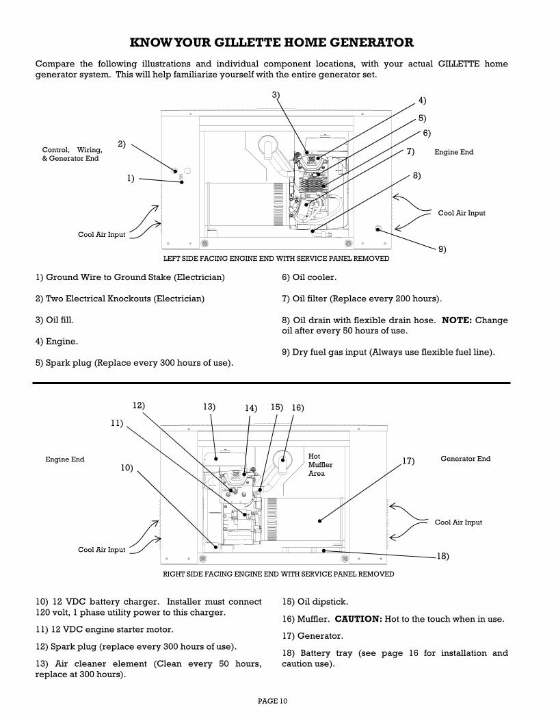
1) Ground Wire to Ground Stake (Electrician)
2) Two Electrical Knockouts (Electrician)
3) Oil fill.
4) Engine.
5) Spark plug (Replace every 300 hours of use).
6) Oil cooler.
7) Oil filter (Replace every 200 hours).
8) Oil drain with flexible drain hose. NOTE: Change
oil after every 50 hours of use.
9) Dry fuel gas input (Always use flexible fuel line).
KNOW YOUR GILLETTE HOME GENERATOR
Compare the following illustrations and individual component locations, with your actual GILLETTE home
generator system. This will help familiarize yourself with the entire generator set.
10) 12 VDC battery charger. Installer must connect
120 volt, 1 phase utility power to this charger.
11) 12 VDC engine starter motor.
12) Spark plug (replace every 300 hours of use).
13) Air cleaner element (Clean every 50 hours,
replace at 300 hours).
15) Oil dipstick.
16) Muffler. CAUTION: Hot to the touch when in use.
17) Generator.
18) Battery tray (see page 16 for installation and
caution use).
Control, Wiring,
& Generator End Engine End
LEFT SIDE FACING ENGINE END WITH SERVICE PANEL REMOVED
Cool Air Input
Cool Air Input
1)
9)
2)
3) 4)
5)
6)
7)
8)
Engine End Hot
Muffler
Area
Generator End
RIGHT SIDE FACING ENGINE END WITH SERVICE PANEL REMOVED
Cool Air Input
Cool Air Input
10)
11)
12) 13) 14) 15) 16)
17)
18)

PAGE 11
The control panel is the central point for all automatic controls and
wiring points. This panel is made, so that repair person can easily
remove it from control box, for easier service.
Following is a listing of parts and their descriptions, as found on
this panel:
A) Engine Monitor: (8) Annunciations consisting of:
High Temperature LED: This is a sensor that will shut gen-set
down, if certain engine temp-limits are exceeded. At this high
temp point, LED lights, until high temp is reduced.
Over Crank: Engine will crank for 10 seconds, rest for 10 seconds,
and continue for a total of (3) cycle cranks, before shutdown and
over crank LED turns on.
Over Speed: If speed of gen-set exceeds 300 VAC (69 HZ), the gen
-set shuts down and over speed LED will constantly flash while
engine is cranking, and when over speed fault occurs.
Engine Running: Engine is running normally and system is
functioning as it should. LED light will constantly flash during
cranking and remain steady while engine is running.
Under Speed/Fail: If engine should reduce in speed below 53 HZ,
the system will shut down and LED turns on.
Low Oil: If engine oil pressure becomes too low, the engine will
shutdown and LED light turns on.
Not in Standby: When mode selector switch is in the “Test”
position, the “Not in Standby” LED remains on, to remind operator
that gen-set is not in “Standby” position. When the setup and
testing procedures are finished, remember to place mode switch in
“Standby” position.
Low Battery: If 12 VDC starting battery drops below 11 VDC, LED
turns on and remains until battery voltage is corrected.
B) Mode Selector Switch: Control switch for manual testing and
standby (auto) position. After each fault condition happens and
fault is repaired, mode switch must be placed in “OFF/RESET”
position for 15 seconds, to reset the microprocessor control board,
before returning to normal operation.
C) Hour Meter: Total hours of use and is used as service reminder.
D) Main Line Circuit Breaker: UL-146 circuit breaker will trip
open upon short circuits, or overloads.
KNOW YOUR SYSTEM CONTROL PANEL Compare the illustration with actual GILLETTE home generator system.
1) 8 Point, LED diagnostic display panel.
2) #S-2 optional alarm system interface for fault detection.
3) TS1: Electrician’s connection terminals for 2-Point Remote
Start/Stop Dry Contact Terminals.
4) TS2: Electrician’s 120 VAC Utility Power connection terminals
for powering optional equipment i.e. battery charger, oil heater,
battery blanket, etc…
TS3: Electrician’s connection terminals for 120/240 VAC
Generator Output Power.
5) Dotted line indicates cover shield protecting unauthorized
person’s from entering high voltage area. Licensed electrician is
required to remove hex head bolt (5), slide dotted line panel down
by approx. 2” and pull straight out, for full wiring access. Note: 20
amp fuse is removed from fuse holder and taped to upper part of
panel #3 for electricians installation
OVER CRANK
LOW OIL
NOT IN STANDBY
LOW BATTERY
UNDER SPEED / FAIL
ENGINE RUNNING
OVER SPEED
HIGH TEMPERATURE
ENGINE MONITOR
Gby GILLETTE GENERATORS, Inc.
SENTRY-PRO
OFF / RESET
TEST STANDBY
MODE SELECTOR
MAIN LINECIRCUI BREAKER
Control and connection points on generator end, shown
with safety cover removed and access door opened.
1)
2) 3)
5)
4)
TO CHARGER,
HEATERS, ETC.
120/240 VOLTS
GENERATOR POWER
TO E1, N, & E2
REMOTE
START
TO ATS
120V 1PH
UTILITY POWER
TO EXTERIOR OF
HOUSING GROUND
120/240 VOLTS
GENERATOR POWER 4)
3)
1) Note: See page 18 for additional engine monitor highlights
CAUTION A bolted cover shields
these three wiring
connection points and
should be accessed only
by licensed electricians.
(see page 16)
OVER CRANK
LOW OIL
NOT IN STANDBY
LOW BATTERY
UNDER SPEED / FAIL
ENGINE RUNNING
OVER SPEED
HIGH TEMPERATURE
ENGINE MONITOR
Gby GILLETTE GENERATORS, Inc.
SENTRY-PRO
OFF / RESET
TEST STANDBY
MODE SELECTOR
MAIN LINE
CIRCUI BREAKER
A
B C
D CIRCUIT BREAKER
FACTORY WIRED
INSTALLER WIRED
PAGE 12
Propane (LPG) and natural gas (NG) is
extremely flammable and explosive.
Fire or explosion can cause serious
burns or death.
LPG is heavier than air and will settle in low areas.
NG is lighter than air and will collect in high areas.
The slightest spark can ignite either fuel and can
cause fire or explosion.
This home standby generator set leaves the factory
set up for natural gas (NG) fuel. This generator can
be ordered with liquid petroleum gas (LP) from the
factory or it can easily be converted at the jobsite
with no special tools or test equipment.
All piping and layout planning must comply with
NFPA 54 (specifications for dry fuel equipment).
Before fuel pipe installation begins, installer should
consult local fuel supplier and the local Fire Marshall
to learn proper codes/regulations for a safe
installation.
Special consideration should be given where local
conditions include flooding, tornados, hurricanes,
earthquakes, or unstable ground for the flexibility
and strength of fuel pipe and pipe connections. Use
an approved gas pipe sealant on all threaded pipe
joints.
All installed gas fuel lines must be purged and leak
tested prior to initial start-up in accordance to local
codes, standards, and regulations.
A minimum of (1) approved manual shut-off gas valve
must be installed in the gas line leading to the
generator. This valve must be easily
accessible.
A furnished, flexible fuel line is to be
installed between stationary fuel supply pipe and fuel
inlet pipe to generator. Always install this flexible
line in a horizontal, straight manner. If it is installed
with a bend of any degree, it may eventually crack at
the bend and cause a gas leak, causing a possible fire
hazard.
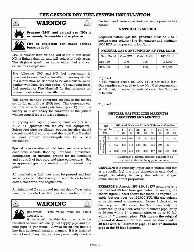
NATURAL GAS FUEL
Required natural gas fuel pressure must be 6 to 8
inches water column (4 to 4½ ounces) and minimum
1000 BTU rating per cubic foot/hour
Figure 1 * BTU Values based on 1000 BTU’s per cubic foot.
Gas supplier may need to know Nat. Gas consumption
at full load, in measurements of cubic feet/hour or
BTU/hour
Figure 2
CAUTION: It is critically important to understand that
as a specific fuel line pipe diameter is extended in
length, its ability to carry the volume of gas,
diminishes in direct proportion.
EXAMPLE 1: A model SPS-120, 11 KW generator is to
be installed 35 feet from gas meter. In reading the
charts: figure 1 chart shows this model to require 195
cubic feet per hour (or 195,000 BTU/HR) gas volume
to be delivered to generator. Figure 2 chart shows
the required 195 cubic feet/hour can only be
delivered up to 30 feet, with ¾” diameter pipe, or up
to 50 feet with a 1” diameter pipe, or up to 90 feet
with a 1¼” diameter pipe. This means the original
planned distance of 35 feet, must be shortened to
30 feet with ¾” diameter pipe, or use 1” diameter
pipe at the 35 feet distance.
NATURAL GAS CONSUMPTION AT FULL LOAD
Gen. Model Gen. KW Cubic Ft./Hr BTU/Hr. *
SPS-120 12.0 195 195,000
SPP-180 16.0 280 280,000
NATURAL GAS FUEL LINE MAXIMUM
DIAMETERS AND LENGTHS
Pipe
Length In
Feet
Allowed Distance From NG Meter to Gen-Set
0-10 11-
20
21-
30
31-
40
41-
50
51-
60
61-
70
71-
80
81-
90
Pip
e D
iam
ete
r
In In
ches
¾ 350 249 200 171 152 138 --- --- ---
1 600 415 342 288 251 224 204 187 ---
1¼ 1265 890 740 628 553 497 455 421 350
Cubic feet of natural gas that can safely be
carried in its matching pipe diameter.
The following LPG and NG fuel information is
provided to assist the fuel installer. In no way should
this information be deemed to be all-inclusive or to
conflict with local dry fuel codes. Consult your local
fuel supplier or Fire Marshall for final answers on
proper local codes and installations.
THE GASEOUS DRY FUEL SYSTEM INSTALLATION
WARNING
WARNING
PAGE 13
EXAMPLE 2: A model SPP-180, 16 KW generator is to
be installed 50 feet from gas meter. In reading the
charts, Fig. 1 shows this model to require 280 cubic
feet/hour (or 280,000 BTU/hr) gas volume to be
delivered to generator. Figure 2 chart show this
required 280 cu.ft. can not be delivered with a ¾” or
1” pipe. Only a 1¼” diameter pipe can safely deliver
the 280 cu.ft. gas requirement, over a 50 foot
distance.
INSTALLER’S RESPONSIBILITY: Use Figure 1
chart to learn cubic feet/hour value of generator to
be installed. Use Figure 2 chart to learn minimum
pipe size diameter and maximum distance from
gas meter, to insure sufficient fuel volume from
natural gas meter to generator set.
CRITICAL POINTS FOR A PROPER
NATURAL GAS INSTALLATION
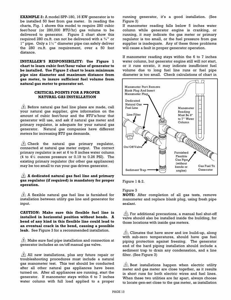
Before natural gas fuel line plans are made, call your natural gas supplier, give information on the
amount of cubic feet/hour and the BTU’s/hour that
generator will use, and ask if natural gas meter and
primary regulator, is adequate for your natural gas
generator. Natural gas companies have different
meters for increasing BTU gas demands.
Check the natural gas primary regulator, connected at natural gas meter output. The correct
primary regulator is set at 6 to 8 inches water column
(4 to 4½ ounces pressure or 0.19 to 0.26 PSI). The
existing primary regulator (for other gas appliances)
may be too small to run your gas driven generator.
A dedicated natural gas fuel line and primary
gas regulator (if required) is mandatory for proper
operation.
A flexible natural gas fuel line is furnished for installation between utility gas line and generator for
input.
CAUTION: Make sure this flexible fuel line is
installed in horizontal position without bends. A
bend of any kind in this flexible line could lead to
an eventual crack in the bend, causing a possible
leak. See Figure 3 for a recommended installation.
Make sure fuel pipe installation and connection at generator includes an on/off manual gas valve.
All new installations, plus any future repair or troubleshooting procedures must include a natural
gas manometer test. This test should be conducted
after all other natural gas appliances have been
turned on. After all appliances are running, start the
generator. If manometer stays within 6 to 7 inches
water column with full load applied to a proper
running generator, it’s a good installation. (See
Figure 3)
If manometer reading falls below 5 inches water
column while generator engine is cranking, or
running, it may indicate the gas meter or primary
regulator is too small, or the fuel pressure from gas
supplier is inadequate. Any of these three problems
will cause a fault in proper generator operation.
If manometer reading stays within the 6 to 7 inches
water column, but generator engine still will not start,
or it runs erratic, it may indicate insufficient fuel
volume due to long fuel line runs or fuel pipe
diameter is too small. Check calculations of chart in
Figure 1 & 2.
Figure 3
NOTE: After completion of all gas tests, remove
manometer and replace blank plug, using fresh pipe
sealant.
For additional precautions, a manual fuel shut-off valve should also be installed inside the building, for
those locations with inside gas meters.
Climates that have snow and ice build-up, along with sub-zero temperatures, should have gas fuel
piping protection against freezing. The generator
end of the hard piping installation should include a
sediment trap to drain any condensation, and a line
filter. (See Figure 3)
Best installations happen when electric utility meter and gas meter are close together, as it results
in short runs for both electric wires and fuel lines.
When these two utilities are far apart, always choose
to locate gen-set close to the gas meter, as installation
Sediment Trap
Dedicated
Natural GasFuel Line Manometer
ReadingMust Be 6”
to 7” WaterColumn
Gas Fuel To
Generator
On/Off Valve
Furnished
FlexibleGas Pipe
(withoutbends or
angles)
Manometer Port: Remove
Blank Plug And InsertManometer Plug
Line Filter
PAGE 14
LPG GAS FUEL
This home generator system has been set up at the
factory for natural gas fuel, unless it has been
specifically ordered for vapor withdrawal liquid
propane gas (LPG). This installation/operation guide
will explain the factory LPG system. Additional
information is available upon request for field
conversion from one fuel to the other.
LPG fuel is typically at farms or remote areas where
there is no natural gas fuel.
LPG must be a vapor withdrawal system (the
generator will not work on liquid withdrawal
systems). Proper LPG is clean and free of moisture
or particulate matter. It consists of a propane HD5
grade with minimum 2500 BTU’s per cubic foot
energy rating. A typical blend is 5% propylene and
butane plus a minimum 90% propane.
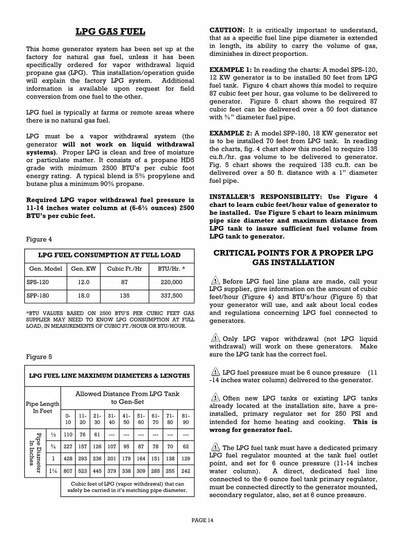
Required LPG vapor withdrawal fuel pressure is
11-14 inches water column at (6-6½ ounces) 2500
BTU’s per cubic feet.
Figure 4
*BTU VALUES BASED ON 2500 BTU’S PER CUBIC FEET GAS
SUPPLIER MAY NEED TO KNOW LPG CONSUMPTION AT FULL
LOAD, IN MEASUREMENTS OF CUBIC FT./HOUR OR BTU/HOUR.
Figure 5
CAUTION: It is critically important to understand,
that as a specific fuel line pipe diameter is extended
in length, its ability to carry the volume of gas,
diminishes in direct proportion.
EXAMPLE 1: In reading the charts: A model SPS-120,
12 KW generator is to be installed 50 feet from LPG
fuel tank. Figure 4 chart shows this model to require
87 cubic feet per hour, gas volume to be delivered to
generator. Figure 5 chart shows the required 87
cubic feet can be delivered over a 50 foot distance
with ¾” diameter fuel pipe.
EXAMPLE 2: A model SPP-180, 18 KW generator set
is to be installed 70 feet from LPG tank. In reading
the charts, fig. 4 chart show this model to require 135
cu.ft./hr. gas volume to be delivered to generator.
Fig. 5 chart shows the required 135 cu.ft. can be
delivered over a 50 ft. distance with a 1” diameter
fuel pipe.
INSTALLER’S RESPONSIBILITY: Use Figure 4
chart to learn cubic feet/hour value of generator to
be installed. Use Figure 5 chart to learn minimum pipe size diameter and maximum distance from
LPG tank to insure sufficient fuel volume from
LPG tank to generator.
CRITICAL POINTS FOR A PROPER LPG GAS INSTALLATION
Before LPG fuel line plans are made, call your LPG supplier, give information on the amount of cubic
feet/hour (Figure 4) and BTU’s/hour (Figure 5) that
your generator will use, and ask about local codes
and regulations concerning LPG fuel connected to
generators.
Only LPG vapor withdrawal (not LPG liquid withdrawal) will work on these generators. Make
sure the LPG tank has the correct fuel.
LPG fuel pressure must be 6 ounce pressure (11-14 inches water column) delivered to the generator.
Often new LPG tanks or existing LPG tanks already located at the installation site, have a pre-
installed, primary regulator set for 250 PSI and
intended for home heating and cooking. This is
wrong for generator fuel.
The LPG fuel tank must have a dedicated primary LPG fuel regulator mounted at the tank fuel outlet
point, and set for 6 ounce pressure (11-14 inches
water column). A direct, dedicated fuel line
connected to the 6 ounce fuel tank primary regulator,
must be connected directly to the generator mounted,
secondary regulator, also, set at 6 ounce pressure.
LPG FUEL CONSUMPTION AT FULL LOAD
Gen. Model Gen. KW Cubic Ft./Hr BTU/Hr. *
SPS-120 12.0 87 220,000
SPP-180 18.0 135 337,500
LPG FUEL LINE MAXIMUM DIAMETERS & LENGTHS
Pipe Length
In Feet
Allowed Distance From LPG Tank
to Gen-Set
0-
10
11-
20
21-
30
31-
40
41-
50
51-
60
61-
70
71-
80
81-
90
Pip
e D
iam
ete
r
In In
ches
½ 110 76 61 --- --- --- --- --- ---
¾ 227 157 126 107 95 87 78 70 62
1 428 293 236 201 179 164 151 138 129
1¼ 807 523 445 379 338 309 285 255 242
Cubic feet of LPG (vapor withdrawal) that can
safely be carried in it’s matching pipe diameter.
PAGE 15
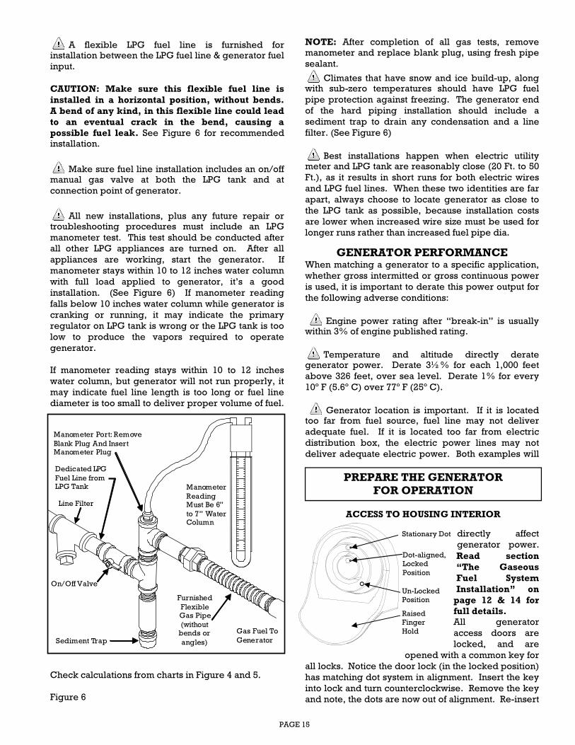
A flexible LPG fuel line is furnished for installation between the LPG fuel line & generator fuel
input.
CAUTION: Make sure this flexible fuel line is
installed in a horizontal position, without bends.
A bend of any kind, in this flexible line could lead
to an eventual crack in the bend, causing a possible fuel leak. See Figure 6 for recommended
installation.
Make sure fuel line installation includes an on/off manual gas valve at both the LPG tank and at
connection point of generator.
All new installations, plus any future repair or troubleshooting procedures must include an LPG
manometer test. This test should be conducted after
all other LPG appliances are turned on. After all
appliances are working, start the generator. If
manometer stays within 10 to 12 inches water column
with full load applied to generator, it’s a good
installation. (See Figure 6) If manometer reading
falls below 10 inches water column while generator is
cranking or running, it may indicate the primary
regulator on LPG tank is wrong or the LPG tank is too
low to produce the vapors required to operate
generator.
If manometer reading stays within 10 to 12 inches
water column, but generator will not run properly, it
may indicate fuel line length is too long or fuel line
diameter is too small to deliver proper volume of fuel.
Check calculations from charts in Figure 4 and 5.
Figure 6
NOTE: After completion of all gas tests, remove
manometer and replace blank plug, using fresh pipe
sealant.
Climates that have snow and ice build-up, along with sub-zero temperatures should have LPG fuel
pipe protection against freezing. The generator end
of the hard piping installation should include a
sediment trap to drain any condensation and a line
filter. (See Figure 6)
Best installations happen when electric utility meter and LPG tank are reasonably close (20 Ft. to 50
Ft.), as it results in short runs for both electric wires
and LPG fuel lines. When these two identities are far
apart, always choose to locate generator as close to
the LPG tank as possible, because installation costs
are lower when increased wire size must be used for
longer runs rather than increased fuel pipe dia.
GENERATOR PERFORMANCE
When matching a generator to a specific application,
whether gross intermitted or gross continuous power
is used, it is important to derate this power output for
the following adverse conditions:
Engine power rating after “break-in” is usually within 3% of engine published rating.
Temperature and altitude directly derate generator power. Derate 3½% for each 1,000 feet
above 326 feet, over sea level. Derate 1% for every
10º F (5.6º C) over 77º F (25º C).
Generator location is important. If it is located too far from fuel source, fuel line may not deliver
adequate fuel. If it is located too far from electric
distribution box, the electric power lines may not
deliver adequate electric power. Both examples will
directly affect
generator power.
Read section
“The Gaseous
Fuel System
Installation” on
page 12 & 14 for full details. All generator
access doors are
locked, and are
opened with a common key for
all locks. Notice the door lock (in the locked position)
has matching dot system in alignment. Insert the key
into lock and turn counterclockwise. Remove the key
and note, the dots are now out of alignment. Re-insert
PREPARE THE GENERATOR FOR OPERATION
Stationary Dot
Dot-aligned,
Locked
Position
Un-Locked
Position
Raised
Finger
Hold
ACCESS TO HOUSING INTERIOR
Sediment Trap
Dedicated LPG
Fuel Line fromLPG Tank Manometer
ReadingMust Be 6”
to 7” WaterColumn
Gas Fuel To
Generator
On/Off Valve
Furnished
FlexibleGas Pipe
(withoutbends or
angles)
Manometer Port: Remove
Blank Plug And InsertManometer Plug
Line Filter
PAGE 16
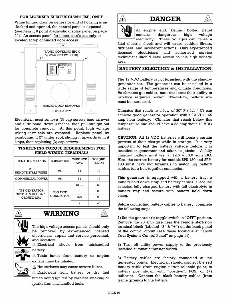
Electrician must remove (3) cap screws (see arrows)
and slide panel down 2 inches, then pull straight out
for complete removal. At this point, high voltage
wiring terminals are exposed. Replace panel by
positioning it 2” under roof, sliding it upwards until it
stops, then replacing (3) cap screws.
The high voltage access panels should only
be removed by experienced licensed
electricians, repair and service personnel,
and installers.
Electrical shock from mishandled
battery.
Toxic fumes from battery or engine
exhaust may be inhaled.
Hot surfaces may cause severe burns.
Explosions from battery or dry fuel
fumes being ignited by careless smoking or
sparks from mishandled tools.
At engine end, behind bolted panel
contains dangerous high voltage
electricity. These voltages can cause a
fatal electric shock and will cause sudden illness,
dizziness, and incoherent actions. Only experienced
licensed electricians and authorized service
technicians should have access to this high voltage
area.
The 12 VDC battery is not furnished with the standby
generator set. The generator can be installed in a
wide range of temperatures and climate conditions.
As climates get colder, batteries loose their ability to
produce required power. Therefore, battery size
must be increased.
Climates that reach to a low of 30º F (-1.1 º C) can
achieve good generator operation with a 12 VDC, 45
amp hour battery. Climates that reach below this
temperature line should have a 55 amp/hour 12 VDC
battery.
CAUTION: All 12 VDC batteries will loose a certain
percent of their charge while in storage. It is very
important to test the battery voltage before it is
installed in generator and taken to jobsite. A fully
charged battery must test at 12.5 – 13.0 volts DC.
Also, the correct battery for models SPS-120 and SPP-
180 must have lug terminals to match lug battery
cables, for a bolt-together connection.
This generator is equipped with a battery tray, a
battery hold down strap and battery cables. Place the
selected fully charged battery with full electrolyte in
battery tray and secure with battery hold down
clamp.
Before connecting battery cables to battery, complete
the following steps:
1) Set the generator’s toggle switch to “OFF” position.
Remove the 20 amp fuse near the remote start/stop
terminal block (labeled “S” & “+”) on the back panel
of the control circuit (see these locations at “Know
Your Systems Control Panel” on page 11).
2) Turn off utility power supply to the previously
installed automatic transfer switch.
3) Battery cables are factory connected at the
generator points. Electrician should connect the red
battery cable (from engine starter solenoid point) to
battery post shown with “positive”, POS, or (+)
indicator. Connect the black battery cables (from
frame ground) to the battery.
DANGER
BATTERY SELECTION & INSTALLATION
WARNING
FOR LICENSED ELECTRICIAN’S USE, ONLY
When hinged door on generator end of housing is un
-locked and opened, the control panel is exposed.
(see item 1, 8 point diagnostic display panel on page
11). An access panel, for electrician’s use only, is
located at top of hinged door access.
TIGHTENING TORQUE REQUIREMENTS FOR
FIELD WIRING TERMINALS
FIELD CONNECTION SCREW SIZE WIRE SIZE
AWG
TORQUE
(LB/IN)
TS1
REMOTE START WIRES #6 14 12
COMMERCIAL POWER #6 14 12
TS2 GENERATOR
OUTPUT & EXTERNAL
GROUND LUG
18-10 20
8 25
6-3 35
2 40
LUG TYPE
CONNECTOR
HIGH TEMPERATURE
ENGINE MONITOR
OVER CRANK
OVER SPEED
ENGINE RUNNING
UNDER SPEED / FAIL
LOW OIL
NOT IN STANDBY
LOW BATTERY
MODE SELECTOR
TEST
OFF / RESET
STANDBY
SenDEC
ON ON
50 AMPCIRCUIT BREAKER
HINGED DOOR REMOVED
FOR CLARITY
(PANEL COVERING HIGH
VOLTAGE TERMINALS)
PAGE 17
Dielectric grease should be used on battery lugs or
posts to help in the prevention of normal corrosion.
Damage will result to generator controls, if battery
cables are made in reverse connections.
Inspect, clean, or re-grease battery connections ever
60-90 days.
In cold climate areas, where temperatures normally
reach 10º F (-12º C) or colder, a battery wrap-around
heater, controlled by thermostat, should be used, for
increased battery power.
This generator is equipped with an automatic “float
type” battery trickle charger, energized by utility
power, to maintain full battery power while on
standby (non-running) condition. CAUTION: This
trickle charger can not recharge a fully discharged or
defective battery.
● Do not dispose of battery in a fire. The
battery is capable of exploding and
spewing electrolyte in several directions.
● Do not open up a battery. It has
electrolyte and is harmful to the skin and
eyes, and is toxic.
● Battery electrolyte is electrically
conductive and corrosive.
● Contact with battery acid will cause
severe burns to the skin and eyes.
A battery can cause an electrical shock. Before
working on a battery, follow safe procedures:
● Remove the start/stop 20 amp fuse in control
circuit.
● Remove all rings, watches, & other metal objects.
● Wear rubber gloves and boots.
● Use tools with insulated handles.
● Do not lay tools or metal objects on top of battery.
● Disconnect the battery charger before working on
battery terminals.
A battery can cause a chemical burn. Before working
on a battery, follow safe procedures:
● Wear full eye protection and protective clothing.
● When battery electrolyte contacts the skin, wash it
off immediately with water.
● When battery electrolyte contacts the eyes, flush
immediately and repeatedly with water and seek
medical help.
● Spilled electrolyte should be washed away with an
acid neutralizing product.
● A battery can cause fire or explosion because they
emit hydrogen gas.
● Do not smoke or cause any type of flame within 30
feet from battery.
● Discharge body static electricity from body, by
touching a grounded metal surface, before working
on battery.
Before checking oil, always move controller selector
switch to “OFF/RESET” position, and remove 20 amp
fuse.
1) Oil Considerations: Check the oil to make sure it’s
at the proper level. Remove the oil dipstick, wipe it
clean, re-install oil dipstick, then remove it again to
check the oil level. See diagram on page 18.
Crankcase pressure can blow hot engine oil out the
fill opening, causing severe burns. Always stop the
gen-set before removing oil dipstick or oil fill cap.
Use API SJ 10W-30 oil for temperatures above 32º F
(0º C). All gen-sets are shipped with this grade oil.
WARNING
DANGER
BATTERIES CAN CAUSE
DANGEROUS CHEMICAL BURNS
FINAL PREPARATIONS BEFORE INITIAL START-UP
BATTERIES CAN CAUSE FIRE OR
EXPLOSION
BEFORE WORKING ON BATTERY:
● Always remove 20 amp fuse in control panel.
● Always turn the “auto-off-manual” switch to off
position.
BATTERIES CAN CAUSE
DANGEROUS ELECTRICAL SHOCK
NOTICE
PAGE 18
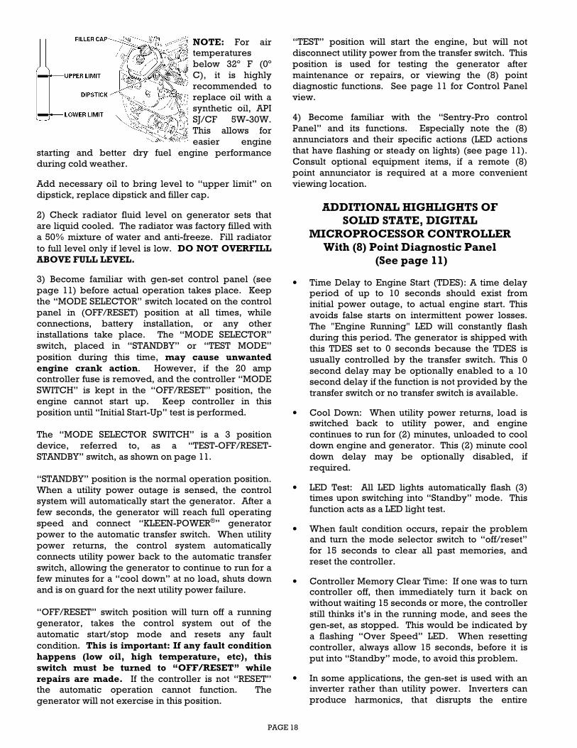
NOTE: For air
temperatures
below 32º F (0º
C), it is highly
recommended to
replace oil with a
synthetic oil, API
SJ/CF 5W-30W.
This allows for
easier engine
starting and better dry fuel engine performance
during cold weather.
Add necessary oil to bring level to “upper limit” on
dipstick, replace dipstick and filler cap.
2) Check radiator fluid level on generator sets that
are liquid cooled. The radiator was factory filled with
a 50% mixture of water and anti-freeze. Fill radiator
to full level only if level is low. DO NOT OVERFILL
ABOVE FULL LEVEL.
3) Become familiar with gen-set control panel (see
page 11) before actual operation takes place. Keep
the “MODE SELECTOR” switch located on the control
panel in (OFF/RESET) position at all times, while
connections, battery installation, or any other
installations take place. The “MODE SELECTOR”
switch, placed in “STANDBY” or “TEST MODE”
position during this time, may cause unwanted
engine crank action. However, if the 20 amp
controller fuse is removed, and the controller “MODE
SWITCH” is kept in the “OFF/RESET” position, the
engine cannot start up. Keep controller in this
position until “Initial Start-Up” test is performed.
The “MODE SELECTOR SWITCH” is a 3 position
device, referred to, as a “TEST-OFF/RESET-
STANDBY” switch, as shown on page 11.
“STANDBY” position is the normal operation position.
When a utility power outage is sensed, the control
system will automatically start the generator. After a
few seconds, the generator will reach full operating
speed and connect “KLEEN-POWER®” generator
power to the automatic transfer switch. When utility
power returns, the control system automatically
connects utility power back to the automatic transfer
switch, allowing the generator to continue to run for a
few minutes for a “cool down” at no load, shuts down
and is on guard for the next utility power failure.
“OFF/RESET” switch position will turn off a running
generator, takes the control system out of the
automatic start/stop mode and resets any fault
condition. This is important: If any fault condition
happens (low oil, high temperature, etc), this
switch must be turned to “OFF/RESET” while
repairs are made. If the controller is not “RESET”
the automatic operation cannot function. The
generator will not exercise in this position.
“TEST” position will start the engine, but will not
disconnect utility power from the transfer switch. This
position is used for testing the generator after
maintenance or repairs, or viewing the (8) point
diagnostic functions. See page 11 for Control Panel
view.
4) Become familiar with the “Sentry-Pro control
Panel” and its functions. Especially note the (8)
annunciators and their specific actions (LED actions
that have flashing or steady on lights) (see page 11).
Consult optional equipment items, if a remote (8)
point annunciator is required at a more convenient
viewing location.
ADDITIONAL HIGHLIGHTS OF SOLID STATE, DIGITAL
MICROPROCESSOR CONTROLLER With (8) Point Diagnostic Panel
(See page 11)
• Time Delay to Engine Start (TDES): A time delay period of up to 10 seconds should exist from
initial power outage, to actual engine start. This
avoids false starts on intermittent power losses.
The "Engine Running" LED will constantly flash
during this period. The generator is shipped with
this TDES set to 0 seconds because the TDES is
usually controlled by the transfer switch. This 0
second delay may be optionally enabled to a 10
second delay if the function is not provided by the
transfer switch or no transfer switch is available.
• Cool Down: When utility power returns, load is switched back to utility power, and engine
continues to run for (2) minutes, unloaded to cool
down engine and generator. This (2) minute cool
down delay may be optionally disabled, if
required.
• LED Test: All LED lights automatically flash (3) times upon switching into “Standby” mode. This
function acts as a LED light test.
• When fault condition occurs, repair the problem and turn the mode selector switch to “off/reset”
for 15 seconds to clear all past memories, and
reset the controller.
• Controller Memory Clear Time: If one was to turn controller off, then immediately turn it back on
without waiting 15 seconds or more, the controller
still thinks it’s in the running mode, and sees the
gen-set, as stopped. This would be indicated by
a flashing “Over Speed” LED. When resetting
controller, always allow 15 seconds, before it is
put into “Standby” mode, to avoid this problem.
• In some applications, the gen-set is used with an inverter rather than utility power. Inverters can
produce harmonics, that disrupts the entire
PAGE 19
NG
LP
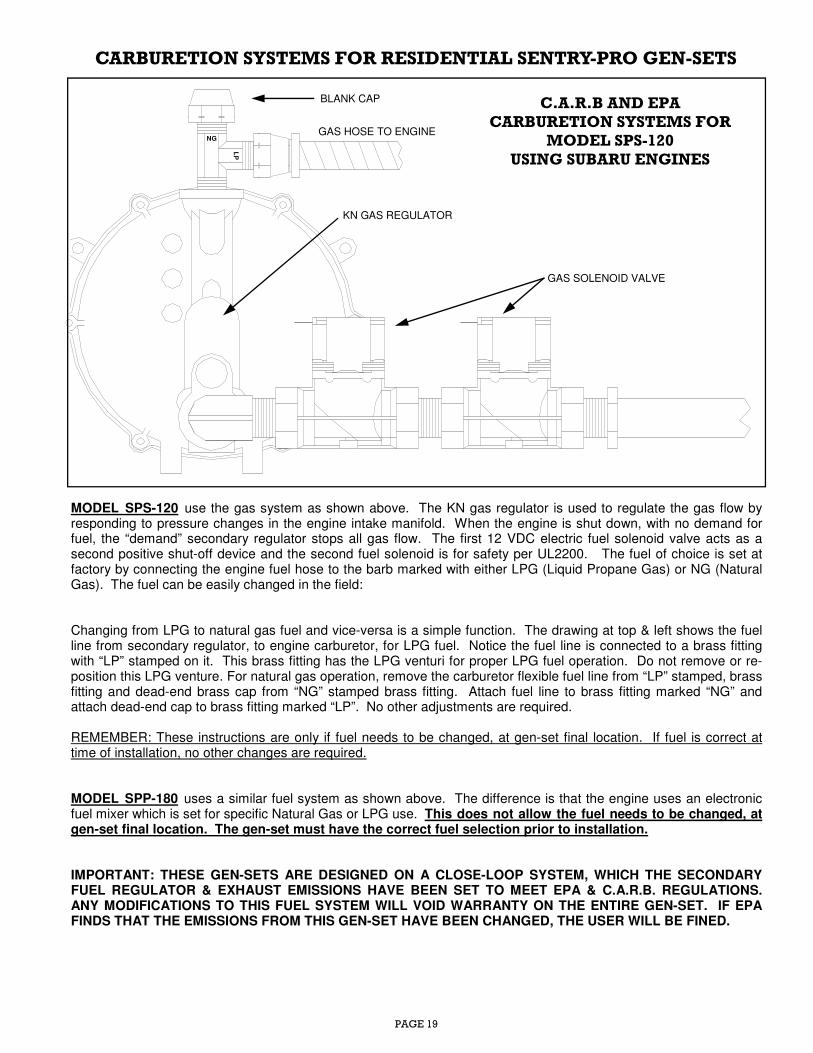
MODEL SPS-120 use the gas system as shown above. The KN gas regulator is used to regulate the gas flow by responding to pressure changes in the engine intake manifold. When the engine is shut down, with no demand for fuel, the “demand” secondary regulator stops all gas flow. The first 12 VDC electric fuel solenoid valve acts as a second positive shut-off device and the second fuel solenoid is for safety per UL2200. The fuel of choice is set at factory by connecting the engine fuel hose to the barb marked with either LPG (Liquid Propane Gas) or NG (Natural Gas). The fuel can be easily changed in the field: Changing from LPG to natural gas fuel and vice-versa is a simple function. The drawing at top & left shows the fuel line from secondary regulator, to engine carburetor, for LPG fuel. Notice the fuel line is connected to a brass fitting with “LP” stamped on it. This brass fitting has the LPG venturi for proper LPG fuel operation. Do not remove or re-position this LPG venture. For natural gas operation, remove the carburetor flexible fuel line from “LP” stamped, brass fitting and dead-end brass cap from “NG” stamped brass fitting. Attach fuel line to brass fitting marked “NG” and attach dead-end cap to brass fitting marked “LP”. No other adjustments are required. REMEMBER: These instructions are only if fuel needs to be changed, at gen-set final location. If fuel is correct at time of installation, no other changes are required. MODEL SPP-180 uses a similar fuel system as shown above. The difference is that the engine uses an electronic fuel mixer which is set for specific Natural Gas or LPG use. This does not allow the fuel needs to be changed, at gen-set final location. The gen-set must have the correct fuel selection prior to installation. IMPORTANT: THESE GEN-SETS ARE DESIGNED ON A CLOSE-LOOP SYSTEM, WHICH THE SECONDARY FUEL REGULATOR & EXHAUST EMISSIONS HAVE BEEN SET TO MEET EPA & C.A.R.B. REGULATIONS. ANY MODIFICATIONS TO THIS FUEL SYSTEM WILL VOID WARRANTY ON THE ENTIRE GEN-SET. IF EPA FINDS THAT THE EMISSIONS FROM THIS GEN-SET HAVE BEEN CHANGED, THE USER WILL BE FINED.
CARBURETION SYSTEMS FOR RESIDENTIAL SENTRY-PRO GEN-SETS
KN GAS REGULATOR
GAS HOSE TO ENGINE
GAS SOLENOID VALVE
C.A.R.B AND EPA
CARBURETION SYSTEMS FOR MODEL SPS-120
USING SUBARU ENGINES
BLANK CAP
PAGE 20
BE EXTREMELY CAREFUL. YOU ARE READY TO
TEST RUN A GENERATOR THAT HAS BOTH
ELECTRIC SHOCK AND FLAMMABLE FUEL
POTENTIAL HAZARDS. CHECK AND REVIEW
ENTIRE INSTALLATION BEFORE START-UP.
MAKE SURE THAT RATING OF TRANSFER
SWITCH, MATCHES OR IS MORE THAN THE RATING OF THE EMERGENCY GENERATOR, IN
VOLTS, PHASE, AND FREQUENCY.
MISMATCHED SPECIFICATIONS WILL CAUSE
EQUIPMENT DAMAGE. A) All models will allow either natural gas or LPG to
be connected to fuel input line. It may be necessary
for a minor adjustment to be made at “engine load
adjustment screw”, during initial start-up, or when
changing from one fuel to another. See page 19 for
more details.
B) C.A.R.B and EPA CARBURETION SYSTEMS: The
secondary gas regulator has (2) separate fuel inputs.
One is marked “LP” and the second is marked “NG”.
When using LPG, the fuel hose from engine
carburetor must be connected to the regulator input
“LP” with a dead plug attached to the “NG” input.
When Natural Gas is used, the fuel hose is connected
to the “NG” input, with a dead plug attached to the
“LP” input. It’s just that simple to change fuel input, in
the field. See page 19 for further details.
C) Model SPP-180: This model is designed for specific
fuel use on the mixer with specific pressure. There is
no fuel change available in the field or at the factory.
The gen-set must be ordered for either LPG or
Natural Gas No other adjustments are required.
At this time, before the initial start-up is performed,
the 20 amp fuse is still removed from controller and
the “MODE SELECTOR” switch is at “OFF/RESET”.
Also, fully charged battery is connected, oil level is
correct, coolant in radiator (if liquid cooled set is
being tested) is correct, and all listed requirements,
leading up to the initial start has been completed.
When the automatic start/stop system is activated, it
may cause an unwanted start cycle. Be very cautious
of these possible, sudden engine starts.
STEP 1: Replace 20 amp fuse in its proper position on
control panel, and keep the “MODE SELECTOR”
switch on “OFF/RESET” position. Also, turn off the
main 2-pole, automatic circuit breaker (item “D” on
control panel, page 11). Apply electric utility power
to connected automatic transfer switch (ATS).
STEP 2: Turn the “MODE SELECTOR” switch, located
on the control panel, from “OFF/RESET” position to
“TEST” position. This will establish the first engine
start cycle. With the “ENGINE RUNNING” lamp
(located on the annunciator panel) flashing, after a 10
second time delay, the generator should crank over
and start. NOTE: If a special controller is used that
does not allow for a 10 second delay to start (for
hospitals or nursing homes), the engine will
immediately start cranking, when switch is placed in
“TEST” mode. Allow engine to run for approximately
2 minutes. Then return the engine test switch to the
“OFF/RESET” position. The engine will then shut
down.
If the engine should fail to start, for some reason, the
engine will crank for 10 seconds, rest for 10 seconds,
and continue for a total (3) attempt cycle cranks
before a complete shutdown occurs, and
“Overcrank” LED energizes on 8 point annunciator.
Check all gas connections and shut off valves.
REMEMBER: This no start problem is a “Fault” and
when fault is corrected, the “MODE SELECTOR”
switch must be turned to “OFF/RESET” to reset the
controller. After 15 seconds, turn the “MODE
SELECTOR” back to “TEST” for another start-run
attempt. Anytime there after, the generator can be
manually test run from this “MODE SELECTOR”
switch by pushing it to the “TEST” position.
STEP 3: During this initial testing time, it is advised to
test the voltage at no load conditions, and at full load
conditions. Repeat the manual start process. Turn
the “MODE SELECTOR” switch, located on the gen-
set, from “OFF/RESET” position to “TEST” position.
This will establish another engine start attempt. The
engine should crank steadily, and after a few seconds
start running. The generator set is now running and
will remain running until “MODE SELECTOR” switch
is returned to the “OFF/RESET” position. Do not
move the switch from the “TEST MODE” position
at this time. Allow engine to run un-loaded for 5-10
minutes to warm up. This gives installer time to
perform certain quality tests. Use an AC Voltmeter
INITIAL START-UP
CAUTION
START-UP USING MANUAL TEST MODE
WARNING
PROCEED WITH CAUTION. THE CONTROL
PANEL IS NOW “LIVE” WITH UTILITY POWER.
CONTACT WITH THESE “LIVE” TERMINALS INSIDE TRANSFER SWITCH AND GENERATOR
CONTROL PANEL WILL RESULT IN SHOCK AND
POSSIBLE DEATH WILL RESULT.
CAUTION
SELECTING THE FUEL
PAGE 21
voltage and frequency at no load conditions. Typical
no load test readings should be 230-245 volts at 61.0-
61.5 hertz. After all meter tests are complete, return
the “MODE SELECTOR” switch to the “OFF/RESET”
position. The engine will then shut down.
STEP 4: When all connections, adjustments, and tests
are completed, and the automatic transfer switch is
installed and wired, the standby generator system is
ready to be placed on standby duty. When testing the
packaged standby set, using the furnished Automatic
Transfer Swtich (ATS), refer to included wiring
diagrams & ATS owners manual. For an ATS system
furnished by others, follow instructions and wiring
diagrams furnished with the separate ATS system.
STEP 5: EXERCISER: Each automatic transfer switch
has an exerciser circuit that automatically starts and
runs gen-set for a predetermined time, before it shuts
down. This “Trial Run” feature is to ensure that
system is working and ready to use, when you need
it, the most. The automatic engine exerciser must be
set for the automatic time to come on, run for a pre-set
time, then automatically shut itself down. The
installer must set the initial exercising time,
depending on the needs of owner. Review the ATS
manual for exercising operation.
IT IS IMPORTANT TO KNOW, THAT WHEN
EXERCISING THE SELECTION OF NOT
TRANSFERRING THE LOAD TO THE
GENERATOR SET, IS THE MOST DESIRABLE
METHOD.
It is possible that a different auto transfer switch may
be used, rather that the Gillette furnished automatic
transfer switch (ATS). In this case, any different style
or brand, 2-wire ATS will work with generator
circuitry. Consult the owners guide and its wiring
diagrams, for any different ATS system, for its method
of operation.
STEP 6: Simulate a utility power failure by turning off
disconnect switch, installed between utility power
and auto transfer switch. The auto transfer switch will
activate. The "Engine Running" LED (located on
control panel) will flash repeatedly for up to 10
seconds (normal time delay to start) until engine
begins to start and run. (This may be set to 0 seconds
depending on the specific setup at this location.) The
auto transfer switch will switch the connected load
from utility to emergency generator power.
Note that engine generator set must start under an
immediately applied load. In most cases, the gen-set
is strong enough to perform under this demanding
scenario. However, if the load is 75% or more
inductive (large motors, UPS systems, large air
conditioners), it may be necessary to install a time
delay device, allowing gen-set to get up and running
(approx. 10 seconds), then allow load to be applied.
STEP 7: Return the disconnect switch to on position,
allowing utility power, to no longer be interrupted.
The auto transfer switch will sense this and switch the
connected load from emergency generator power,
back to utility power. The engine will continue to run
for 2 minutes and will allow engine and generator to
normally cool down, without connected load.
Optional: The sensing device may not always be 2-
wire automatic transfer switch. Many auto start/stop,
2-wire sensing devices such as pressure switch, float
switch, temperature switch, may control the start/stop
functions of Sentry-Pro gen-sets, under special
custom applications. However, the operating
procedures, as described above, are always the
same.
AIR FILTER: remove air filter cover and existing air
filter element and foam element. Reassemble air
filter with new air filter elements in place. Do not oil
the filter elements.
OIL FILTER: remove oil filter by turning it
counterclockwise, using an oil filter wrench. Clean
the gasket sealing surface of oil filter holder. Apply a
light coat of clean oil to the rubber seal of the new oil
filter. Dispose of old filter in an environmentally safe
manner. NOTE: Best time to replace oil filter is
during time of oil change, when oil is drained from
engine.
GENERAL SERVICE TIPS
CAUTION
If the 3 position switch is left in the “STANDBY”
position at any time, the generator system is being
serviced or repaired, the engine may crank and start
without warning. Such automatic starting may
happen when utility voltage dips below a preset
voltage level or during a normal exercise period. To
prevent possible injury that may be caused, always
set the “TEST-OFF/REST-STANDBY” switch to “OFF/
RESET” position and remove the 20 amp cartridge
fuse, while working on or around the generator set,
or accompanying automatic transfer switch.
CAUTION
THE ELECTRIC LOAD TO BE APPLIED TO
GENERATOR SET MUST NEVER BE MORE THAT
GENERATOR RATINGS. THE GENERATOR IS RATED IN WATTS. CALCULATE THE
ELECTRICAL LOAD TO BE APPLIED TO
GENERATOR IN WATTS. NEVER EXCEED 75%
OF GENERATOR RATING IN ACTUAL
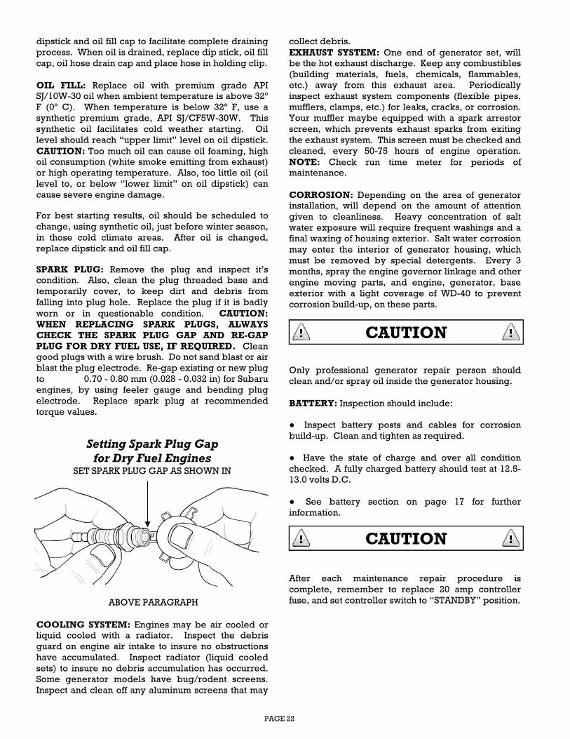
PAGE 22
dipstick and oil fill cap to facilitate complete draining
process. When oil is drained, replace dip stick, oil fill
cap, oil hose drain cap and place hose in holding clip.
OIL FILL: Replace oil with premium grade API
SJ/10W-30 oil when ambient temperature is above 32º
F (0º C). When temperature is below 32º F, use a
synthetic premium grade, API SJ/CF5W-30W. This
synthetic oil facilitates cold weather starting. Oil
level should reach “upper limit” level on oil dipstick.
CAUTION: Too much oil can cause oil foaming, high
oil consumption (white smoke emitting from exhaust)
or high operating temperature. Also, too little oil (oil
level to, or below “lower limit” on oil dipstick) can
cause severe engine damage.
For best starting results, oil should be scheduled to
change, using synthetic oil, just before winter season,
in those cold climate areas. After oil is changed,
replace dipstick and oil fill cap.
SPARK PLUG: Remove the plug and inspect it’s
condition. Also, clean the plug threaded base and
temporarily cover, to keep dirt and debris from
falling into plug hole. Replace the plug if it is badly
worn or in questionable condition. CAUTION:
WHEN REPLACING SPARK PLUGS, ALWAYS CHECK THE SPARK PLUG GAP AND RE-GAP
PLUG FOR DRY FUEL USE, IF REQUIRED. Clean
good plugs with a wire brush. Do not sand blast or air
blast the plug electrode. Re-gap existing or new plug
to 0.70 - 0.80 mm (0.028 - 0.032 in) for Subaru
engines, by using feeler gauge and bending plug
electrode. Replace spark plug at recommended
torque values.
Setting Spark Plug Gap for Dry Fuel Engines
SET SPARK PLUG GAP AS SHOWN IN
ABOVE PARAGRAPH
COOLING SYSTEM: Engines may be air cooled or
liquid cooled with a radiator. Inspect the debris
guard on engine air intake to insure no obstructions
have accumulated. Inspect radiator (liquid cooled
sets) to insure no debris accumulation has occurred.
Some generator models have bug/rodent screens.
Inspect and clean off any aluminum screens that may
collect debris.
EXHAUST SYSTEM: One end of generator set, will
be the hot exhaust discharge. Keep any combustibles
(building materials, fuels, chemicals, flammables,
etc.) away from this exhaust area. Periodically
inspect exhaust system components (flexible pipes,
mufflers, clamps, etc.) for leaks, cracks, or corrosion.
Your muffler maybe equipped with a spark arrestor
screen, which prevents exhaust sparks from exiting
the exhaust system. This screen must be checked and
cleaned, every 50-75 hours of engine operation.
NOTE: Check run time meter for periods of
maintenance.
CORROSION: Depending on the area of generator
installation, will depend on the amount of attention
given to cleanliness. Heavy concentration of salt
water exposure will require frequent washings and a
final waxing of housing exterior. Salt water corrosion
may enter the interior of generator housing, which
must be removed by special detergents. Every 3
months, spray the engine governor linkage and other
engine moving parts, and engine, generator, base
exterior with a light coverage of WD-40 to prevent
corrosion build-up, on these parts.
Only professional generator repair person should
clean and/or spray oil inside the generator housing.
BATTERY: Inspection should include:
● Inspect battery posts and cables for corrosion
build-up. Clean and tighten as required.
● Have the state of charge and over all condition
checked. A fully charged battery should test at 12.5-
13.0 volts D.C.
● See battery section on page 17 for further
information.
After each maintenance repair procedure is
complete, remember to replace 20 amp controller
fuse, and set controller switch to “STANDBY” position.
CAUTION
CAUTION
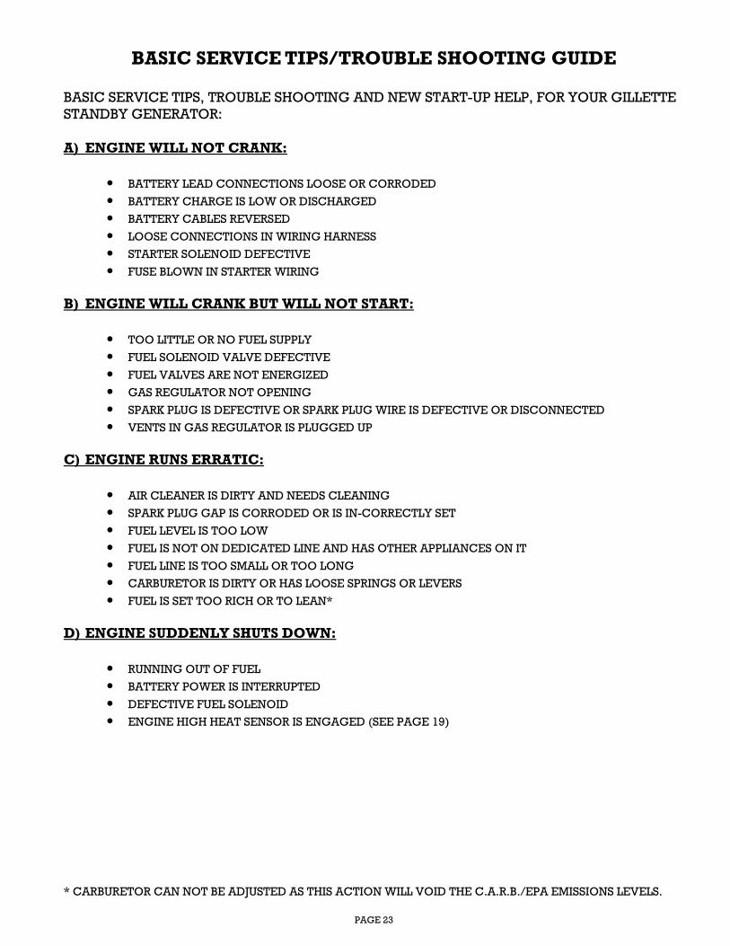
PAGE 23
BASIC SERVICE TIPS/TROUBLE SHOOTING GUIDE
BASIC SERVICE TIPS, TROUBLE SHOOTING AND NEW START-UP HELP, FOR YOUR GILLETTE
STANDBY GENERATOR:
A) ENGINE WILL NOT CRANK:
• BATTERY LEAD CONNECTIONS LOOSE OR CORRODED
• BATTERY CHARGE IS LOW OR DISCHARGED
• BATTERY CABLES REVERSED
• LOOSE CONNECTIONS IN WIRING HARNESS
• STARTER SOLENOID DEFECTIVE
• FUSE BLOWN IN STARTER WIRING
B) ENGINE WILL CRANK BUT WILL NOT START:
• TOO LITTLE OR NO FUEL SUPPLY
• FUEL SOLENOID VALVE DEFECTIVE
• FUEL VALVES ARE NOT ENERGIZED
• GAS REGULATOR NOT OPENING
• SPARK PLUG IS DEFECTIVE OR SPARK PLUG WIRE IS DEFECTIVE OR DISCONNECTED
• VENTS IN GAS REGULATOR IS PLUGGED UP
C) ENGINE RUNS ERRATIC:
• AIR CLEANER IS DIRTY AND NEEDS CLEANING
• SPARK PLUG GAP IS CORRODED OR IS IN-CORRECTLY SET
• FUEL LEVEL IS TOO LOW
• FUEL IS NOT ON DEDICATED LINE AND HAS OTHER APPLIANCES ON IT
• FUEL LINE IS TOO SMALL OR TOO LONG
• CARBURETOR IS DIRTY OR HAS LOOSE SPRINGS OR LEVERS
• FUEL IS SET TOO RICH OR TO LEAN*
D) ENGINE SUDDENLY SHUTS DOWN:
• RUNNING OUT OF FUEL
• BATTERY POWER IS INTERRUPTED
• DEFECTIVE FUEL SOLENOID
• ENGINE HIGH HEAT SENSOR IS ENGAGED (SEE PAGE 19)
* CARBURETOR CAN NOT BE ADJUSTED AS THIS ACTION WILL VOID THE C.A.R.B./EPA EMISSIONS LEVELS.
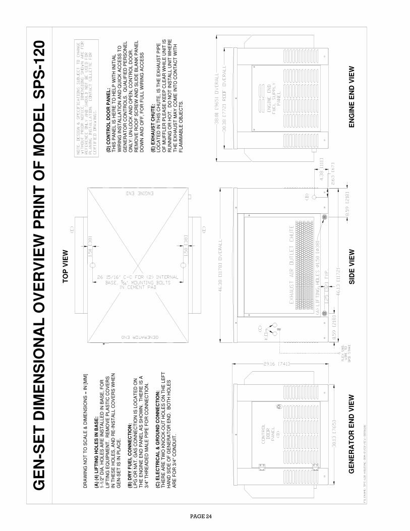
PAGE 24
DR
AW
ING
NO
T T
O S
CA
LE
& D
IME
NS
ION
S =
IN
[M
M]
(A)
(4)
LIF
TIN
G H
OL
ES
IN
BA
SE
:1
-1/2
" D
IA.
HO
LE
S A
RE
IN
ST
AL
LE
D I
N B
AS
E, F
OR
LIF
TIN
G E
QU
IPM
EN
T.
RE
MO
VE
PL
AS
TIC
CO
VE
RS
IN T
HE
SE
HO
LE
S, A
ND
RE
-IN
ST
AL
L C
OV
ER
S W
HE
NG
EN
-SE
T I
S I
N P
LA
CE
.
(B)
DR
Y F
UE
L C
ON
NE
CT
ION
:
LP
G O
R N
AT
. G
AS
CO
NN
EC
TIO
N I
S L
OC
AT
ED
ON
TH
E E
NG
INE
EN
D P
AN
EL A
S S
HO
WN
. T
HE
RE
IS
A3
/4"
TH
RE
AD
ED
MA
LE
PIP
E F
OR
CO
NN
EC
TIO
N.
(C)
EL
EC
TR
ICA
L &
GR
OU
ND
CO
NN
EC
TIO
N:
TH
ER
E A
RE
TW
O K
NO
CK
-OU
T H
OL
ES
ON
TH
E L
EF
TH
AN
D S
IDE
OF
GE
NE
RA
TO
R E
ND
. B
OT
H H
OL
ES
AR
E F
OR
3/4
" C
ON
DU
IT.
(D)
CO
NT
RO
L D
OO
R P
AN
EL
:T
HIS
PA
NE
L IS
HE
RE
TO
HE
LP
WIT
H I
NIT
IAL
WIR
ING
IN
ST
AL
LA
TIO
N A
ND
QU
ICK
AC
CE
SS
TO
GE
NE
RA
TO
R C
ON
TR
OL
S.
QU
AL
IFIE
D P
ER
SO
NE
LO
NL
Y:
UN
-LO
CK
AN
D O
PE
N,
CO
NT
RO
L D
OO
R.
RE
MO
VE
RO
OF
SC
RE
W A
ND
SL
IDE
BLA
NK
PA
NE
LD
OW
N A
ND
OF
F,
FO
R F
UL
L W
IRIN
G A
CC
ES
S
(E)
EX
HA
US
T C
HU
TE
:L
OC
AT
ED
IN
TH
IS C
HU
TE
, IS
TH
E E
XH
AU
ST
PIP
EO
F M
UF
FLE
R P
LE
AS
E K
EE
P C
LE
AR
WH
ILE
UN
IT I
SR
UN
NIN
G O
R H
OT
. D
O N
OT
IN
ST
AL
L U
NIT
WH
ER
ET
HE
EX
HA
US
T M
AY
CO
ME
IN
TO
CO
NT
AC
T W
ITH
FLA
MM
AB
LE
OB
JEC
TS
.
ENGINE END VIEW
GENERATOR END VIEW
SIDE VIEW
TOP VIEW
GEN−SET DIM
ENSIONAL OVERVIEW PRINT OF MODEL SPS−120
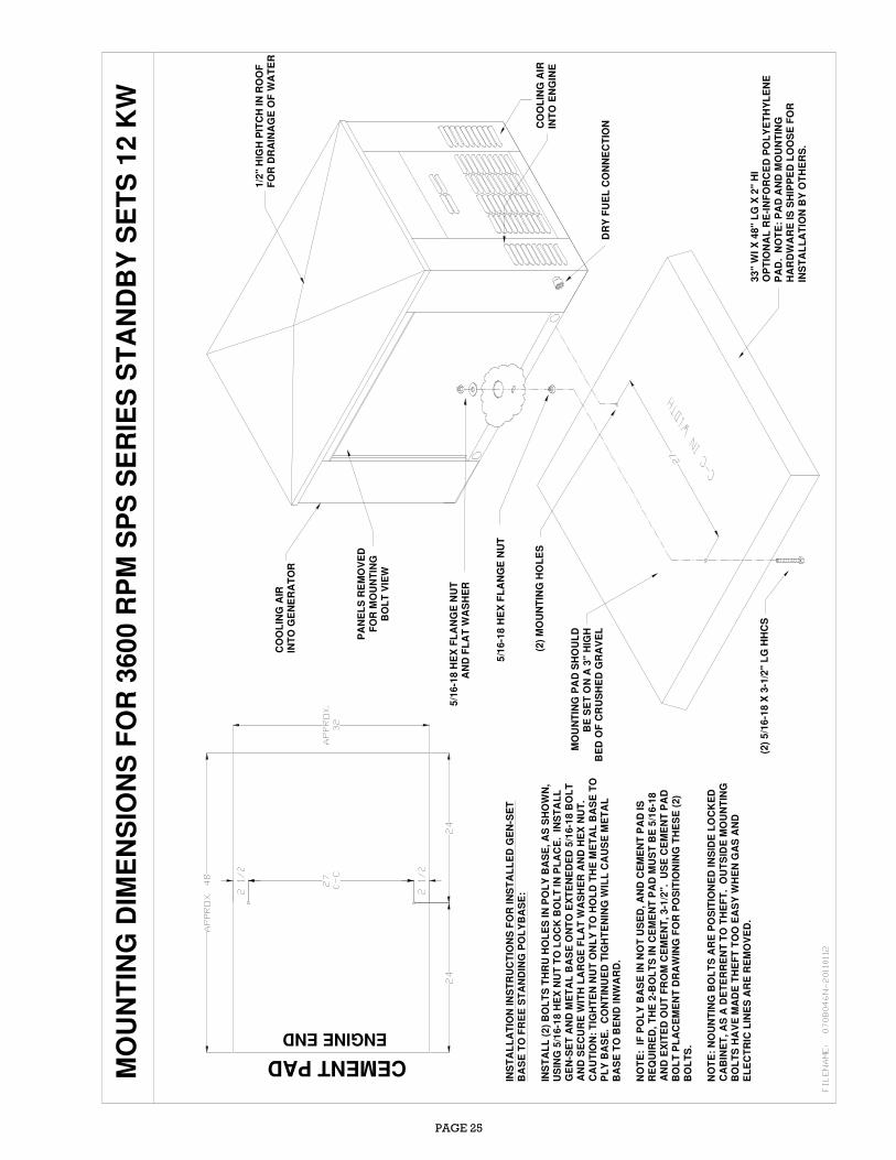
PAGE 25
ENGINE END
PANELS REMOVED
FOR M
OUNTING
BOLT VIEW
MO
UN
TIN
G D
IME
NS
ION
S F
OR
36
00
RP
M S
PS
SE
RIE
S S
TA
ND
BY
SE
TS
12
KW
CO
OL
ING
AIR
INT
O E
NG
INE
MO
UN
TIN
G P
AD
SH
OU
LD
BE
SE
T O
N A
3"
HIG
HB
ED
OF
CR
US
HE
D G
RA
VE
L
33
" W
I X
48
" L
G X
2"
HI
OP
TIO
NA
L R
E-I
NF
OR
CE
D P
OL
YE
TH
YL
EN
EP
AD
. N
OT
E:
PA
D A
ND
MO
UN
TIN
GH
AR
DW
AR
E IS
SH
IPP
ED
LO
OS
E F
OR
INS
TA
LL
AT
ION
BY
OT
HE
RS
.
(2)
MO
UN
TIN
G H
OL
ES
1/2
" H
IGH
PIT
CH
IN
RO
OF
FO
R D
RA
INA
GE
OF
WA
TE
RC
OO
LIN
G A
IRIN
TO
GE
NE
RA
TO
R
DR
Y F
UE
L C
ON
NE
CT
ION
INS
TA
LL
AT
ION
IN
ST
RU
CT
ION
S F
OR
IN
ST
AL
LE
D G
EN
-SE
TB
AS
E T
O F
RE
E S
TA
ND
ING
PO
LY
BA
SE
:
INS
TA
LL
(2
) B
OL
TS
TH
RU
HO
LE
S I
N P
OL
Y B
AS
E,
AS
SH
OW
N,
US
ING
5/1
6-1
8 H
EX
NU
T T
O L
OC
K B
OL
T IN
PL
AC
E.
IN
ST
AL
LG
EN
-SE
T A
ND
ME
TA
L B
AS
E O
NT
O E
XT
EN
ED
ED
5/1
6-1
8 B
OL
TA
ND
SE
CU
RE
WIT
H L
AR
GE
FL
AT
WA
SH
ER
AN
D H
EX
NU
T.
CA
UT
ION
: T
IGH
TE
N N
UT
ON
LY
TO
HO
LD
TH
E M
ET
AL
BA
SE
TO
PL
Y B
AS
E.
CO
NT
INU
ED
TIG
HT
EN
ING
WIL
L C
AU
SE
ME
TA
LB
AS
E T
O B
EN
D I
NW
AR
D.
NO
TE
: I
F P
OL
Y B
AS
E IN
NO
T U
SE
D, A
ND
CE
ME
NT
PA
D IS
RE
QU
IRE
D,
TH
E 2
-BO
LT
S IN
CE
ME
NT
PA
D M
US
T B
E 5
/16-1
8A
ND
EX
ITE
D O
UT
FR
OM
CE
ME
NT
, 3-1
/2".
U
SE
CE
ME
NT
PA
DB
OL
T P
LA
CE
ME
NT
DR
AW
ING
FO
R P
OS
ITIO
NIN
G T
HE
SE
(2)
BO
LT
S.
NO
TE
: N
OU
NT
ING
BO
LT
S A
RE
PO
SIT
ION
ED
IN
SID
E L
OC
KE
DC
AB
INE
T,
AS
A D
ET
ER
RE
NT
TO
TH
EF
T. O
UT
SID
E M
OU
NT
ING
BO
LT
S H
AV
E M
AD
E T
HE
FT
TO
O E
AS
Y W
HE
N G
AS
AN
DE
LE
CT
RIC
LIN
ES
AR
E R
EM
OV
ED
.
(2)
5/1
6-1
8 X
3-1
/2"
LG
HH
CS
5/1
6-1
8 H
EX
FL
AN
GE
NU
TA
ND
FL
AT
WA
SH
ER
5/1
6-1
8 H
EX
FL
AN
GE
NU
T
CEMENT PAD
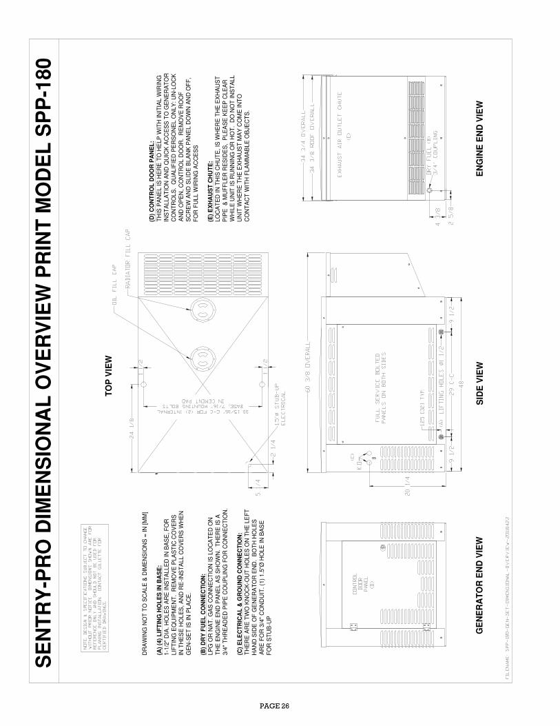
PAGE 26
ENGINE END VIEW
GENERATOR END VIEW
SIDE VIEW
TOP VIEW
SENTRY−PRO DIMENSIONAL OVERVIEW PRINT M
ODEL SPP−180
DR
AW
ING
NO
T T
O S
CA
LE
& D
IME
NS
ION
S =
IN
[M
M]
(A)
(4)
LIF
TIN
G H
OL
ES
IN
BA
SE
:1-1
/2"
DIA
. H
OLE
S A
RE
IN
ST
ALLE
D IN
BA
SE
, F
OR
LIF
TIN
G E
QU
IPM
EN
T. R
EM
OV
E P
LA
ST
IC C
OV
ER
SIN
TH
ES
E H
OL
ES
, A
ND
RE
-IN
ST
ALL C
OV
ER
S W
HE
N
GE
N-S
ET
IS
IN
PLA
CE
.
(B)
DR
Y F
UE
L C
ON
NE
CT
ION
:LP
G O
R N
AT
. G
AS
CO
NN
EC
TIO
N IS
LO
CA
TE
D O
N
TH
E E
NG
INE
EN
D P
AN
EL
AS
SH
OW
N. T
HE
RE
IS
A3/4
" T
HR
EA
DE
D P
IPE
CO
UP
LIN
G F
OR
CO
NN
EC
TIO
N.
(C)
EL
EC
TR
ICA
L &
GR
OU
ND
CO
NN
EC
TIO
N:
TH
ER
E A
RE
TW
O K
NO
CK
-OU
T H
OLE
S O
N T
HE
LE
FT
HA
ND
SID
E O
F G
EN
ER
AT
OR
EN
D. B
OT
H H
OLE
S
AR
E F
OR
3/4
" C
ON
DU
IT. (1
) 1.5
"Ø H
OLE
IN
BA
SE
FO
R S
TU
B-U
P
(D)
CO
NT
RO
L D
OO
R P
AN
EL
:
TH
IS P
AN
EL I
S H
ER
E T
O H
ELP
WIT
H IN
ITIA
L W
IRIN
GIN
ST
ALL
AT
ION
AN
D Q
UIC
K A
CC
ES
S T
O G
EN
ER
AT
OR
CO
NT
RO
LS
. Q
UA
LIF
IED
PE
RS
ON
EL O
NLY
: U
N-L
OC
K
AN
D O
PE
N,
CO
NT
RO
L D
OO
R. R
EM
OV
E R
OO
FS
CR
EW
AN
D S
LID
E B
LA
NK
PA
NE
L D
OW
N A
ND
OF
F,
FO
R F
ULL
WIR
ING
AC
CE
SS
(E)
EX
HA
US
T C
HU
TE
:LO
CA
TE
D I
N T
HIS
CH
UT
E,
IS W
HE
RE
TH
E E
XH
AU
ST
PIP
E
& M
UF
FLE
R R
ES
IDE
S,
PLE
AS
E K
EE
P C
LE
AR
WH
ILE
UN
IT I
S R
UN
NIN
G O
R H
OT
. D
O N
OT
IN
ST
ALL
UN
IT W
HE
RE
TH
E E
XH
AU
ST
MA
Y C
OM
E IN
TO
CO
NT
AC
T W
ITH
FLA
MM
AB
LE
OB
JEC
TS
.
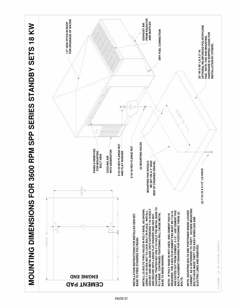
PAGE 27
MO
UN
TIN
G D
IME
NS
ION
S F
OR
36
00 R
PM
SP
P S
ER
IES
ST
AN
DB
Y S
ET
S 1
8 K
W
EXHAUST AIR
FROM RADIATOR
AND M
UFFLER
MOUNTING PAD SHOULD
BE SET ON A 3" HIGH
BED OF CRUSHED GRAVEL
33" WI X 48" LG X 2" HI
OPTIONAL RE−INFORCED POLYETHYLENE
PAD. NOTE: PAD AND M
OUNTING
HARDWARE IS SHIPPED LOOSE FOR
INSTALLATION BY OTHERS.
(2) MOUNTING HOLES
1/2" HIGH PITCH IN ROOF
FOR DRAINAGE OF W
ATER
COOLING AIR
INTO GENERATOR
DRY FUEL CONNECTION
INSTALLATION INSTRUCTIONS FOR INSTALLED GEN−SET
BASE TO FREE STANDING POLYBASE:
INSTALL (2) BOLTS THRU HOLES IN POLY BASE, AS SHOWN,
USING 7/16−18 HEX NUT TO LOCK BOLT IN PLACE. INSTALL
GEN−SET AND METAL BASE ONTO EXTENEDED 7/16−18 BOLT
AND SECURE W
ITH LARGE FLAT W
ASHER AND HEX NUT.
CAUTION: TIGHTEN NUT ONLY TO HOLD THE M
ETAL BASE TO
PLY BASE. CONTINUED TIGHTENING W
ILL CAUSE M
ETAL
BASE TO BEND INWARD.
NOTE: IF POLY BASE IN NOT USED, AND CEMENT PAD IS
REQUIRED, THE 2−BOLTS IN CEMENT PAD MUST BE 7/16−18
AND EXITED OUT FROM CEMENT, 3−1/2". USE CEMENT PAD
BOLT PLACEMENT DRAWING FOR POSITIONING THESE (2)
BOLTS.
NOTE: NOUNTING BOLTS ARE POSITIONED INSIDE LOCKED
CABINET, AS A DETERRENT TO THEFT. OUTSIDE M
OUNTING
BOLTS HAVE M
ADE THEFT TOO EASY W
HEN GAS AND
ELECTRIC LINES ARE REMOVED.
(2) 7/16−18 X 3−1/2" LG HHCS
5/16−18 HEX FLANGE NUT
AND FLAT W
ASHER
5/16−18 HEX FLANGE NUT
CEMENT PAD
ENGINE END
PANELS REMOVED
FOR M
OUNTING
BOLT VIEW
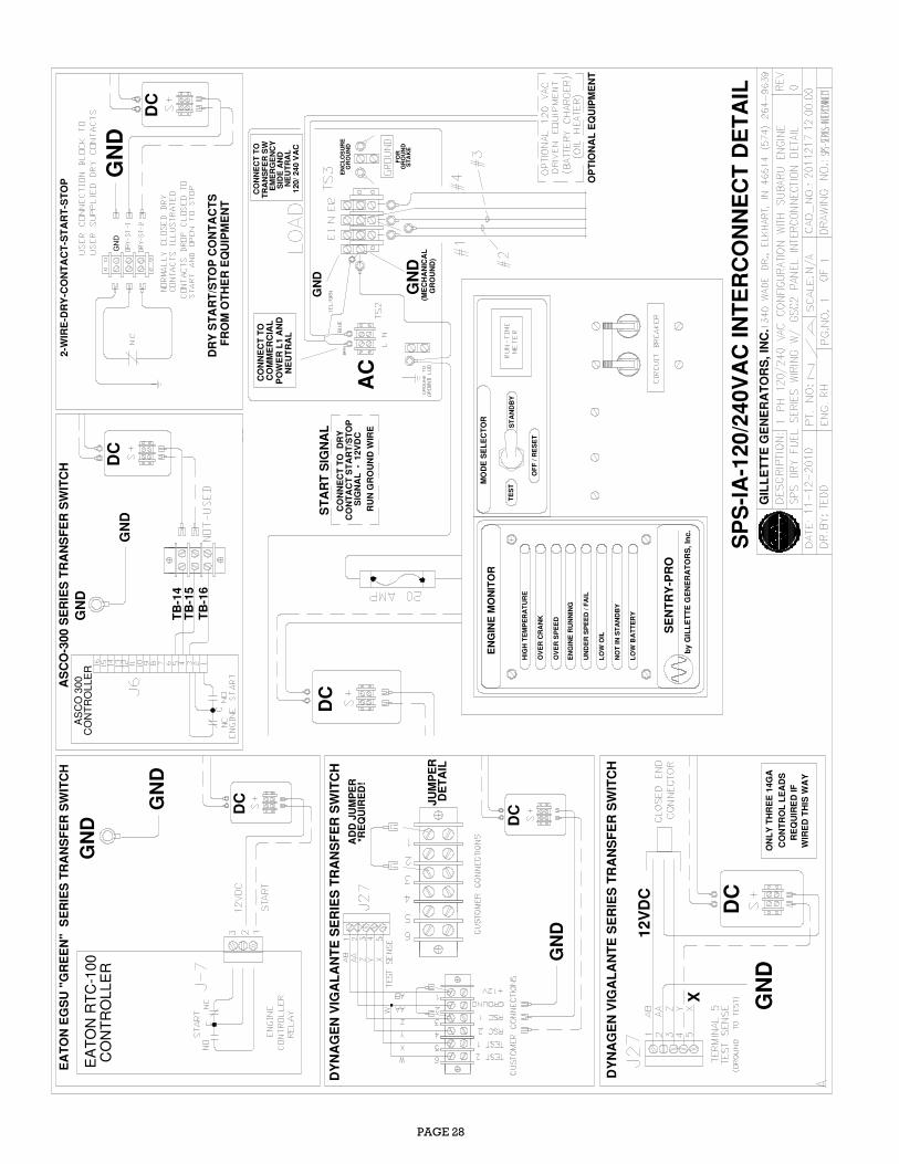
PAGE 28
OV
ER
CR
AN
K
LO
W O
IL
NO
T I
N S
TA
ND
BY
LO
W B
AT
TE
RY
UN
DE
R S
PE
ED
/ F
AIL
EN
GIN
E R
UN
NIN
G
OV
ER
SP
EE
D
EN
GIN
E M
ON
ITO
R
OF
F /
RE
SE
T
TE
ST
ST
AN
DB
Y
MO
DE
SE
LE
CT
OR
by G
ILL
ET
TE
GE
NE
RA
TO
RS
, In
c.
SE
NT
RY
-PR
O
DC
COMMERCIAL
CONNECT TO
POWER L1 AND
START SIGNAL
EATON EGSU "GREEN" SERIES TRANSFER SWITCH
EA
TO
N R
TC
-100
CO
NT
RO
LL
ER
SPS−IA−120/240VAC INTERCONNECT DETAIL
DC
GN
D
2−W
IRE−DRY−CONTACT−START−STOP
GND
GND
GND
DRY START/STOP CONTACTS
FROM OTHER EQUIPMENT
NEUTRAL
ENCLOSURE
GROUND
(MECHANICAL
GROUND)
SIDE AND
120/ 240 VAC
NEUTRAL
CONNECT TO
TRANSFER SW
GROUND
STAKE
FOR
HIG
H T
EM
PE
RA
TU
RE
AC
ADD JUMPER
*REQUIRED!
JUMPER
DETAIL
DYNAGEN VIGALANTE SERIES TRANSFER SWITCH
GND
DC
ONLY THREE 14GA
12VDC
CONTROL LEADS
WIRED THIS W
AY
REQUIRED IF
GND
DYNAGEN VIGALANTE SERIES TRANSFER SWITCH
X
CONNECT TO DRY
CONTACT START/STOP
SIGNAL − 12VDC
RUN GROUND W
IRE
DC
AS
CO
300
CO
NT
RO
LLE
R
TB−14
TB−15
TB−16
ASCO−300 SERIES TRANSFER SWITCH
GND
GND
GND
OPTIONAL EQUIPMENT
DC
DC
GND
EMERGENCY
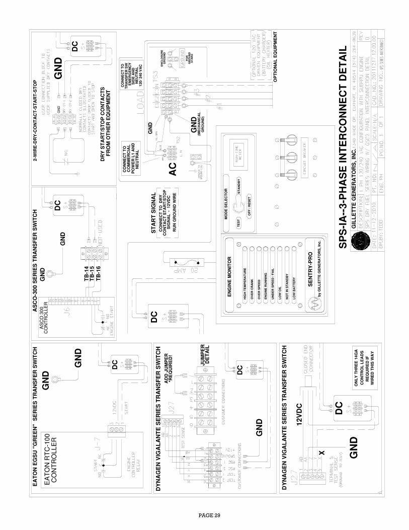
PAGE 29
OV
ER
CR
AN
K
LO
W O
IL
NO
T I
N S
TA
ND
BY
LO
W B
AT
TE
RY
UN
DE
R S
PE
ED
/ F
AIL
EN
GIN
E R
UN
NIN
G
OV
ER
SP
EE
D
EN
GIN
E M
ON
ITO
R
OF
F /
RE
SE
T
TE
ST
ST
AN
DB
Y
MO
DE
SE
LE
CT
OR
by
GIL
LE
TT
E G
EN
ER
AT
OR
S,
Inc.
SE
NT
RY
-PR
O
DC
COMMERCIAL
CONNECT TO
POWER L1 AND
START SIGNAL
SPS−IA−−3−PHASE INTERCONNECT DETAIL
GN
D
2−W
IRE−DRY−CONTACT−START−STOP
GND
DRY START/STOP CONTACTS
FROM OTHER EQUIPMENT
NEUTRAL
ENCLOSURE
GROUND
(MECHANICAL
GROUND)
GROUND
STAKE
FOR
HIG
H T
EM
PE
RA
TU
RE
AC
ADD JUMPER
*REQUIRED!
JUMPER
DETAIL
DYNAGEN VIGALANTE SERIES TRANSFER SWITCH
GND
DC
ONLY THREE 14GA
12VDC
CONTROL LEADS
WIRED THIS W
AY
REQUIRED IF
GND
DYNAGEN VIGALANTE SERIES TRANSFER SWITCH
X
CONNECT TO DRY
CONTACT START/STOP
SIGNAL − 12VDC
RUN GROUND W
IRE
DC
AS
CO
300
CO
NT
RO
LLE
R
TB−14
TB−15
TB−16
ASCO−300 SERIES TRANSFER SWITCH
GND
GND
GND
OPTIONAL EQUIPMENT
DC
DC
GND
EATON EGSU "GREEN" SERIES TRANSFER SWITCH
EA
TO
N R
TC
-10
0C
ON
TR
OLL
ER
DC
GND
GND
SIDE AND
120/ 240 VAC
NEUTRAL
CONNECT TO
TRANSFER SW
EMERGENCY
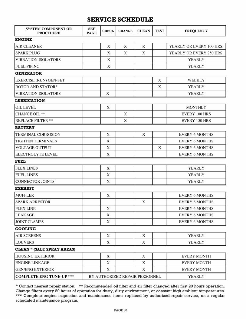
PAGE 30
SERVICE SCHEDULE
SYSTEM COMPONENT OR
PROCEDURE
SEE
PAGE CHECK CHANGE CLEAN TEST FREQUENCY
ENGINE
AIR CLEANER X X R YEARLY OR EVERY 100 HRS.
SPARK PLUG X X X YEARLY OR EVERY 250 HRS.
VIBRATION ISOLATORS X YEARLY
FUEL PIPING X YEARLY
GENERATOR
EXERCISE (RUN) GEN-SET X WEEKLY
ROTOR AND STATOR* X YEARLY
VIBRATION ISOLATORS X YEARLY
LUBRICATION
OIL LEVEL X MONTHLY
CHANGE OIL ** X EVERY 100 HRS
REPLACE FILTER ** X EVERY 150 HRS
BATTERY
TERMINAL CORROSION X X EVERY 6 MONTHS
TIGHTEN TERMINALS X EVERY 6 MONTHS
VOLTAGE OUTPUT X X EVERY 6 MONTHS
ELECTROLYTE LEVEL X EVERY 6 MONTHS
FUEL
FLEX LINES X YEARLY
FUEL LINES X YEARLY
CONNECTOR JOINTS X YEARLY
EXHAUST
MUFFLER X EVERY 6 MONTHS
SPARK ARRESTOR X EVERY 6 MONTHS
FLEX LINE X EVERY 6 MONTHS
LEAKAGE X EVERY 6 MONTHS
JOINT CLAMPS X EVERY 6 MONTHS
COOLING
AIR SCREENS X X YEARLY
LOUVERS X X YEARLY
CLEAN * (SALT SPRAY AREAS)
HOUSING EXTERIOR X X EVERY MONTH
ENGINE LINKAGE X X EVERY MONTH
GEN/ENG EXTERIOR X X EVERY MONTH
COMPLETE ENG TUNE-UP *** BY AUTHORIZED REPAIR PERSONNEL YEARLY
* Contact nearest repair station. ** Recommended oil filter and air filter changed after first 20 hours operation.
Change filters every 50 hours of operation for dusty, dirty environment, or constant high ambient temperatures.
*** Complete engine inspection and maintenance items replaced by authorized repair service, on a regular
scheduled maintenance program.

PAGE 31
MAINTENANCE RECORD
Use the following table to keep a record of all periodic and unscheduled maintenance and service. See
Service Schedule
Record the name, address, and phone number of your authorized GILLETTE service center.
DATE
HOUR
METER
READING
MAINTENANCE OR SERVICE PERFORMED
GILLETTE GENERATORS
AUTOMATIC POWER SYSTEMS
OGU08-OWN-798-20121029
Gillette Generators, Inc.
1340 Wade Drive
Elkhart, IN 46514
Phone: 574-264-9639
Fax: 574-262-1840
E-mail: [email protected]
www.gillettegenerators.com
Call for Tech Support: 1-866-537-4388
Email: [email protected]
Recommended